

Introduction
The capacity for symbolism, in which there is an arbitrary relationship between a communicative signal and a particular referent, is a key element of human language; it allows for increased specificity, diversity and abstraction in communication than would be possible through miming or using holistic signals. Acheulean bifacial handaxes, as some of the earliest examples of artefacts whose form is not dictated by that of the natural substrate on which they are made (Roche Reference Roche, Roux and Bril2005), have been interrogated as proto-symbols (Le Tensorer Reference Le Tensorer2006); though they are more usually seen as having an indexical meaning directly related to their function (Cole Reference Cole, Wynn and Coolidge2016; Pope et al. Reference Pope, Wells and Watson2006; Rossano Reference Rossano2010; Wynn & Berlant Reference Wynn, Berlant, Overmann and Coolidge2019). Meanwhile, neuroanatomical links have been documented between spoken language and knapping refined Acheulean handaxes in modern experimental subjects (Stout & Chaminade Reference Stout and Chaminade2012). At the 480,000-year-old Acheulean site of Boxgrove in southern Britain it has been suggested that the planning and co-operation evident ‘could only be serviced by speech’ (Roberts Reference Roberts1996). Here we investigate two aspects of handaxe-knapping technology that may indicate a form of symbolic communication with lexical specificity was a feature of hominin social behaviour at Boxgrove.
Boxgrove, Sussex, is an Acheulean site on the south coast of Britain. The main hominin occupation dates to the end of the Marine Isotope Stage 13 interglacial, about 480,000 years ago, preceding the mid-point of the Middle Pleistocene in Marine Isotope Stage 12 (Bates et al. Reference Bates, Parfitt and Roberts1997; Roberts & Parfitt Reference Roberts and Parfitt1999). Of the different localities excavated in the Boxgrove landscape, the Q1/B waterhole has yielded hundreds of pristine condition handaxes preserved within silts and fine sands laid down by freshwater from springs situated to the north of the locality. The hominin occupation represented in these sediments seems to have been short-lived, with the sequence probably representing less than 100 years (Pope et al. Reference Pope, Roberts, Maxted and Jones2009), thereby providing a rare window into handaxe form and technology on the order of just one or two generations. Boxgrove handaxes were all made from primary flint nodules derived from the chalk cliffs immediately to the north of the site (Pope & Roberts Reference Pope, Roberts, Gamble and Porr2005; Roberts & Parfitt Reference Roberts and Parfitt1999). While most Boxgrove handaxes were made through façonnage reduction of flint nodules and slabs, a minority were made on large flake blanks (García-Medrano et al. Reference García-Medrano, Ollé, Ashton and Roberts2019).
Tranchet flaking is a knapping technique in which the distal end of a handaxe is removed in a single oblique blow, leaving a razor-sharp tip (García-Medrano et al. Reference García-Medrano, Ollé, Ashton and Roberts2019; Roberts et al. Reference Roberts, Parfitt and Pope1997). It is a rare feature of the Acheulean in general, but the prevalence of tranchet at Boxgrove has been suggested to be part of a societal-wide behavioural norm to create a particular handaxe form (Hutchence & Scott Reference Hutchence and Scott2021; Leroyer 2016; Reference Leroyer and Klaric2018; Shipton & White Reference Shipton and White2020). Social norms are a keystone of symbolic language, as they are how a society collectively agrees on meanings for arbitrary signals (e.g. Zlatev & Blomberg Reference Zlatev, Blomberg, Mäkilähde, Leppänen and Itkonen2019).
Another knapping technique proposed to have been in use at Boxgrove is managing the striking plane through a process known as turning-the-edge (Leroyer Reference Leroyer2016; Shipton Reference Shipton, Wynn, Overmann and Coolidge2023). This involves small flake removals to raise the plane of intersection towards one of the two biface surfaces, which then allows for invasive flaking across that surface to remove mass from the centre of the biface — thereby creating a thin tool (Knowles Reference Knowles1953, 38–41). It has been hypothesized that turning-the-edge is too obscure to be reproduced by observation alone, so it may have required symbolic arbitrary referents — a lexicon — in order for its social transmission between hominins (Gärdenfors & Högberg Reference Gärdenfors and Högberg2017; Shipton Reference Shipton, Overmann and Coolidge2019).
In this paper we examine the question of lexicon at Boxgrove using these two aspects of technology: Whether tranchet flaking can be regarded as a social norm and if turning-the-edge was a feature of knapping at the site?
Turning-the-edge
The Boxgrove handaxes are widely regarded as the pinnacle of Acheulean craftsmanship (Berlant & Wynn Reference Berlant and Wynn2018; Bridgland & White Reference Bridgland and White2015; Hutchence & Debackere Reference Hutchence and Debackere2019; Liu et al. Reference Liu, Khreisheh, Stout and Pargeter2023). The Boxgrove knappers were fortunate in having easy access to large primary clasts of flint, but making refined handaxes is not merely a function of large primary clasts (Shaw & White Reference Shaw and White2003). Boxgrove nodules are highly variable in size and shape, with internal fissures often leading to breaks and smaller, quadrangular blanks, which require reorganization of the knapping schema (García-Medrano et al. Reference García-Medrano, Ollé, Ashton and Roberts2019). Phil Harding describes experimental knapping with the Boxgrove flint: ‘That flint … I won’t say it’s the most awkward, but … it goes in and out, you’ve got a little tiny bit in between all these nodules to get what you want’ (Pitts & Roberts Reference Pitts and Roberts1997, 297).
Boxgrove has, on average, the thinnest handaxes of any Acheulean assemblage (Shipton Reference Shipton2013, 77), with thinning being the most challenging aspect of handaxe manufacture (Liu et al. Reference Liu, Khreisheh, Stout and Pargeter2023; Shipton Reference Shipton2018). For modern knappers to recreate thin bifaces, including those from later prehistory that are much thinner than Acheulean handaxes (e.g. Elkin Reference Elkin1948; Moore Reference Moore2015), requires using the turning-the-edge technique (Knowles Reference Knowles1944; Reference Knowles1953). This technique, also known as platform bevelling, involves striking a series of small flakes, firstly to strengthen a platform by removing fragile overhangs and increasing the platform angle on the edge of the biface, and secondly to raise the plane of intersection between the two surfaces. The biface is then flipped over, and the prepared platform is used to strike a large flake parallel to the surface of the biface, rather than obliquely as in the absence of the technique. Due to the stronger platform, the higher platform angle (Dibble & Rezek Reference Dibble and Rezek2009; Lin et al. Reference Lin, Rezek, Braun and Dibble2013), and the direction of force parallel to the surface, the resulting flake is longer (i.e. more invasive) than it would otherwise be. If it reaches the midline of the biface, it will reduce the overall thickness of the piece. Turning-the-edge may have been used in handaxe production at the transitional Acheulean to Middle Palaeolithic site of Patpara in India (Shipton et al. Reference Shipton, Clarkson and Pal2013), with this assemblage having some of the thinnest bifaces in the Indian Acheulean (Shipton Reference Shipton2016). The same principle of turning-the-edge is used in the Levallois method, with asymmetrically arranged surfaces allowing for the preferential elongate Levallois flake removal. On very thin bifaces, platform facetting will inevitably also turn-the-edge, but on thicker bifaces, like handaxes and Levallois cores, facetting does not necessarily equate to turning-the-edge.
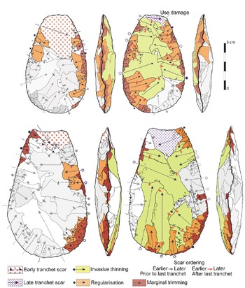
The removal of small platform preparation flakes (facetting) was certainly a technique in use at Boxgrove, with 29.5 per cent of complete flakes >20 mm from Q1/B exhibiting this feature (Stout et al. Reference Stout, Apel, Commander and Roberts2014, 582). One purpose of these facetting flake scars is to give the platform topographical complexity to allow it to withstand a forceful hammer strike, whereas a thin bifacial edge would otherwise be vulnerable to crushing and the strike force then unable to pass through the stone to detach a large flake. This may indeed be the sole reason for the use of platform facetting at Boxgrove; however, facetting removals could also have been used to move the plane of intersection between the two surfaces, as in turning-the-edge. Prepared platform flakes at Q1/B were more elongate than those without this feature (Stout et al. Reference Stout, Apel, Commander and Roberts2014), suggesting enhanced direction of the strike force across the biface surface orthogonal to the lateral margin, as would occur when turning-the-edge. Detailed, diacritical scar-ordering analysis according to the principles of Dauvois (Reference Dauvois1976) on the Boxgrove handaxes has identified examples of turning-the-edge when larger flake removals were used to move the plane of intersection between the two surfaces (Leroyer Reference Leroyer2016) (Fig. 1). Note how the marginal, oblique turning-the-edge scars in phase I raise the plane of intersection so that the thinning flake scars in phase II travel parallel to the surface and are thus more invasive.
Diacritic diagrams of Boxgrove Q1/B handaxes #195 (left) and #4 (right), adapted from Leroyer Reference Leroyer2016. The profile view in the centre pertains to handaxe #195 showing a successive treatment of the surfaces, with platform bevelling removals on both edges after invasive thinning of the lower surface in phase I, giving it a trapezoidal cross-section. This is followed by invasive thinning of the upper surface from both sides in phase II. For handaxe 4 the bevelling on opposite edges in phase I would have produced a parallelogram cross-section to thin the two separate faces of the handaxe from one side each in II. Closed circles show intact initiations, open circles show the inferred locations of missing initiations.

The process of turning-the-edge may be causally opaque to a novice knapper observing an expert performing it (Gärdenfors & Högberg Reference Gärdenfors and Högberg2017). Action analysis has shown the process is the most deeply embedded aspect of knapping in the hierarchical sequence necessary to produce refined handaxes (Muller et al. Reference Muller, Clarkson and Shipton2017). It is removed from the end goal by more chains of causation than are needed for earlier Acheulean biface knapping, being comparable to Levallois in this aspect of hierarchical complexity. Communicating how something fits into a complex hierarchical structure is facilitated by having a specific referent for the individual element or for the ordering of that element (e.g. Langacker Reference Langacker2010; Mithen Reference Mithen2005; Tomasello Reference Tomasello2008; Wray Reference Wray1998).
Turning-the-edge is also visually opaque to an observer (Shipton Reference Shipton, Overmann and Coolidge2019). It would not be clear what relationship the small scars raising the plane of intersection have to the large invasive scars struck from the opposite surface, since it is not possible to see the plane of intersection clearly unless you are holding the handaxe yourself and looking at it side-on; and even if you were doing this, the thin profile of the handaxes means that movements of the plane of intersection might be too subtle for their significance to be noted. Later Acheulean knappers generally (Hicks & Addis Reference Hicks and Addis2025; Wynn Reference Wynn1985), and Boxgrove knappers specifically, paid particular attention to the profile symmetry of the handaxe, with asymmetrical planes of intersection deliberately corrected (Leroyer Reference Leroyer2016, 322). Therefore, to a novice knapper, creating asymmetry through turning-the-edge might look like a mistake.
It has even been suggested that handaxe thinning involves many of the misdirection techniques used by magicians to fool audiences (Lycett & Eren Reference Lycett and Eren2019). The small scars for turning-the-edge would be difficult for an observer to see even if looking over the shoulder of the knapper and would be completely obscured if facing the knapper, as the edge being worked is adjacent to the body of the knapper. If turning-the-edge is done as a separate knapping stage across large parts of the edge, as in Figure 1, the time delay between raising the plane of intersection and the thinning flakes struck from that part of the edge might mask their connection. Understanding the effect of the turning-the-edge scars requires mental rotation of the handaxe as the scars are removed from the opposing surface to that which is to be thinned. An observer’s attention is naturally directed toward the striking hand of the knapper, but the non-dominant hand, which is partially obscured by the handaxe itself, plays two critical roles in invasive thinning: firstly angling the edge of the handaxe with its prepared platform more toward the strike than in the normal mode of biface knapping, and secondly with the fingers on the underside of the handaxe supporting the area of high mass to be removed, so that the strike force travels through the stone rather than exiting early.
Due to the above challenges, it may not have been possible for a novice to understand turning-the-edge biface thinning through observation alone. To visualize this, watch the expert knapper Chris Clarkson making a refined handaxe using turning-the-edge (minutes 6:00–10:00), first muted and then with his commentary: https://www.youtube.com/watch?v=dwon3XJnIRQ. It is possible that turning-the-edge could only be socially transmitted with active teaching using symbolism to refer to non-concurrent subtle features of the knapping process (Gärdenfors & Högberg Reference Gärdenfors and Högberg2017; Shipton Reference Shipton, Overmann and Coolidge2019). It took verbal instruction for Chris Clarkson to master turning-the-edge in practice (Shipton & Nielsen Reference Shipton, Nielsen, Di Paolo, Di Vincenzo and De Petrillo2018). Among Langda bifacial adze knappers in Highland New Guinea, verbal instruction is key in directing the attention of novices to aspects of knapping that they might otherwise miss, such as ‘wait, you have to hit this side first’ (Stout Reference Stout, Nowell and Davidson2010, 174). In an experiment, two groups of novice knappers were taught to make handaxes using either linguistic communication or non-verbal teaching, the latter including observation, assistance in handling, and pointing. A key difference between the groups was only the linguistically taught participants attempted ‘ambitious platform preparation’ (Putt et al. Reference Putt, Woods and Franciscus2014). While the link between a communicative signal and a specific referent could perhaps also have been achieved with a gesture among Acheulean hominins, some form of symbolic instruction seems necessary for turning-the-edge to be learnt.
Given the potential significance of turning-the-edge for symbolic communication, the first goal of this paper is to determine whether it was a widespread feature of handaxe production at Boxgrove. There are, however, multiple difficulties in identifying turning-the-edge. It is often not done as a discrete knapping stage, but to remove specific areas of high topography on a handaxe, so the bevelling can be inverted between the base and the tip of the same edge. The invasive flakes themselves often remove the platform setup flake scars and restore the plane of intersection to a more equal position. Furthermore, thinning is rarely the final stage in biface production, with the extensive profile symmetry correction and outline regularization undertaken on the Boxgrove handaxes typically removing earlier small scars that manipulated the striking plane. In Figure 1, for example, the regularization and marginal trimming scars of phase III would have obscured smaller scars involved in turning-the-edge.
To attempt to identify turning-the-edge, we examine a large sample (>350) of Boxgrove Q1/B bifaces, including roughouts and broken pieces in which earlier stages of manufacture are preserved. We use high-resolution 3D models to see scar topography in the absence of colour variation in the flint.
Tranchet flaking
Tranchet flaking is a distinctive biface knapping technique in which the bifacial tip is removed in a single blow, oblique or transverse to the long axis of the tool, leaving a straight edge formed by a single scar on one surface. Since the tip is formed by a single scar, it is topographically simple rather than having multiple scar boundaries, and the cross-section is concave on one surface as opposed to being biconvex (Fig. 1); both these factors mean tranchet edges are razor sharp. However, they are a rare feature on Acheulean handaxes in general, perhaps partly because they disrupt the symmetry of the tip and regularity of the planform outline, but, more importantly, because tranchet flakes are very difficult to achieve; they require a forceful blow to the biface, which if misjudged is likely to cause an end-shock break whereby the biface cannot sustain the force imparted to it and breaks in half. At the Boxgrove Q1/A locality, 10 out of 25 handaxes suffered from end-shock breaks (Roberts & Parfitt Reference Roberts and Parfitt1999, 339).
Boxgrove has the highest proportion of tranchet flaking of any Acheulean site (Roberts et al. Reference Roberts, Parfitt and Pope1997). Tranchet flaking at the site was sometimes employed as a late-stage sharpening method, perhaps following a phase of use (Pope & Roberts Reference Pope, Roberts, Gamble and Porr2005; Roberts et al. Reference Roberts, Parfitt and Pope1997). Two refitting tranchet flakes on a Boxgrove handaxe from Q2A unit 4c showed the piece had been made elsewhere before being resharpened and discarded at this locality (Pope Reference Pope2002; Roberts & Parfitt Reference Roberts and Parfitt1999, 360–61). At the Boxgrove Horse Butchery locality (GTP17), refit group 50, consisting of 17 late-stage handaxe reduction flakes, was finished with a tranchet attempt before the handaxe was removed from the locality (Pope, Davis & Evans Reference Pope, Davis, Evans, Pope, Parfitt and Roberts2020). However, ‘the formation of the tranchet cutting edge seems, on some occasions at least to have been accomplished at an early stage in the manufacture of the handaxe’ (Woodcock Reference Woodcock1981, 142). Scar-ordering analysis confirms that tranchet flakes were often removed relatively early in the sequence, with the knappers then working around the single scar broad tips they create (Figs 1 & 2) (Leroyer Reference Leroyer2016; Uomini Reference Uomini2006). That tranchet flaking is restricted to the tip of the biface indicates these were conceptually distinguished from normal handaxe tips in the minds of the Boxgrove knappers.
Diacritic diagrams of Boxgrove Q1/B handaxes #142 and #159 from unit 4u, adapted from Leroyer Reference Leroyer2016. Earlier phases of flaking are shown in progressive shading from white (earliest) to darker grey (later). Note that there are tranchet scars on both surfaces but extensive flaking, including invasive thinning, regularization and marginal trimming, took place after the latest of the tranchets was removed. Closed circles show intact initiations, open circles show the inferred locations of missing initiations.

If tranchet was not simply for resharpening, we are left with the question of why these tips are such a common feature at Boxgrove? Experimental use shows that cutting force in handaxes is maximized at the tip (Key & Lycett Reference Key and Lycett2020). However, tranchet flaking is only one among various ways in which flaking is more intensive on handaxe tips across Acheulean assemblages (García-Medrano et al. Reference García-Medrano, Moncel, Maldonado-Garrido, Ollé and Ashton2023), with tip thinning at Boxgrove producing similar results to that from younger Acheulean sites in Britain where tranchet flaking was not prevalent (García-Medrano et al. Reference García-Medrano, Shipton, White and Ashton2022). Certainly, tranchet tips can be sharper with less undulating cutting edges than normal handaxe tips, but this comes at a significant cost of breakage of the tool. Such sharp, straight edges would be more easily obtained by collecting the larger debitage flakes from handaxe production rather than risking breaking the handaxe with a tranchet removal. Tranchet sharpness also only applies to the tip of the handaxe while the cutting edge extends around most of the perimeter on the Boxgrove specimens, and microscopy shows these handaxes were utilized on the more proximal parts of their edges (Mitchell Reference Mitchell1998, 474).
It is possible that there was some peculiar functional need at Boxgrove that was rare or absent in other parts of the Acheulean world. However, the principal function of handaxes at Boxgrove and elsewhere was for butchery (Bello et al. Reference Bello, Parfitt and Stringer2009; Mitchell Reference Mitchell1994; Pope, Roberts & Parfitt, Reference Pope, Roberts and Parfitt2020), and there is nothing unusual about the butchered animals at Boxgrove that would suggest different requirements from other sites in Middle Pleistocene Europe (Pawłowska Reference Pawłowska2017). An alternative hypothesis is that tranchet tips were a prescribed social norm for the Boxgrove hominins (Hutchence & Scott Reference Hutchence and Scott2021; Leroyer 2016; Reference Leroyer and Klaric2018; Shipton & White Reference Shipton and White2020).
Social norms are the behavioural codes of a society that exist independently of individual dyadic relationships (Claidière & Whiten Reference Claidière and Whiten2012). They are intuitively under-appreciated but implicated in a broad range of behaviours including co-operation and morality (Anderson & Dunning Reference Anderson and Dunning2014). In relation to the possible connection between turning-the-edge and symbolic communication discussed above, one noteworthy role of norms is to create society-wide meanings for arbitrary (or pseudo-arbitrary) signals (Itkonen Reference Itkonen, Zlatev, Racine, Sinha and Itkonen2008; Zlatev & Blomberg Reference Zlatev, Blomberg, Mäkilähde, Leppänen and Itkonen2019). The second goal of this study is to explore the relationship between handaxe shape uniformity and tranchet flaking to assess whether the latter can be regarded as a social norm. In themselves, tranchet flakes will reduce the standardization of a handaxe, as the forceful strikes required to remove them necessarily have less control than more delicate removals; and, once struck, they cannot be modified without overprinting the tranchet tip. For example, the tranchet scar on handaxe #4 in Figure 1 has disrupted the outline symmetry of the tip. However, if tranchet is a prescriptive norm, then those knappers adhering to it should also be more concerned with achieving the normative handaxe shape of the group, which is distinctive compared to British Acheulean sites from other interglacials (García-Medrano et al. Reference García-Medrano, Shipton, White and Ashton2022; Shipton & White Reference Shipton and White2020).
First, we test whether Boxgrove handaxe shapes are determined principally by blanks or if they are imposed mental templates, through determining if there is a systematic difference between nodule and flake handaxes. We then test whether handaxe shape is a point on a reduction continuum or a consistent mental template by testing for a relationship between the main parameter of shape variation and reduction intensity. To establish if handaxe shape was stable over the short timeframe represented by Q1/B, we compare handaxe shape between the sets of superimposed handaxe bearing units at the locality: 3c–4u; 4u–4; and 4/3–4 (Roberts & Parfitt Reference Roberts and Parfitt1999; Sánchez-Romero et al. Reference Sánchez-Romero, Benito-Calvo, De Loecker and Pope2023).
We next test whether handaxes with a single tranchet scar are more standardized than those without one, in other words whether they adhere more closely to the target shape. Several of the Boxgrove handaxes have tranchet scars on both surfaces of the tip (Figs 1 & 2) (Uomini Reference Uomini2006), a particularly risky strategy since the tip would already be very sharp with just one, and would also be more vulnerable to breakage with the tranchet concavity already present on the other surface. We test whether these double tranchet handaxes are more standardized again than those with only one tranchet scar.
Materials and methods
A total of 368 Boxgrove Q1/B bifaces housed in the British Museum were scanned using an Artec Spider structured blue light scanner. High-resolution 3D digital models, accurate to ∼0.2 mm, were produced using Artec Studio (v.18) and capped at a total of one million polygons to allow for processing and analysis in AGMT3D. Models will be made freely available upon completion of the Digital Technologies, Acheulean Handaxes and the Social Landscapes of the Lower Palaeolithic project in 2026.
The models included complete handaxes, roughouts and broken handaxes. Of this sample, six (2 per cent) were end-shock broken handaxes. Pieces with cortex on both surfaces were designated as nodule blanks and those with remnant ventral surfaces were designated as flake blanks, with the majority of pieces being indeterminate.
In the program Meshlab, the models were inspected with the colour (textures) turned off to allow for rapid reading of the topography created by flaking patterns. Light source angle was rotated to view scars of different sizes on different parts of the surface. Tranchet scars on either surface were recorded, and possible instances of turning-the-edge noted with screenshots taken.
Model volumes and surface areas were measured in Artec Studio (version 18.1.4.9). The total number of scars was counted, excluding scars <10 mm in maximum dimension though truncated scars assumed to have originated from at least the distance of the current biface edge. Scar counts and surface areas were used to calculate scar density as a measure of reduction intensity (Shipton & Clarkson Reference Shipton and Clarkson2015a).
We used the principles described by Pastoors and colleagues (Reference Pastoors, Tafelmaier and Weniger2015) to determine relative ages of scars. Repeated temporal relationships between different types of scars were then used to infer causal relationships. Any large invasive scars with intact initiations (or initiations close to the current edge) were first identified in plan views of the handaxes (e.g. Figs 1 & 2). Then the profile views of the handaxes were examined for small scars on the adjacent part of the opposing surface. We further noted whether the plane of intersection was positioned closer to the surface with the invasive scars.
Models of complete handaxes were processed using the freeware program AGMT3D (v.3.1) for geometric morphometric and skill variable analyses (Herzlinger & Grosman Reference Herzlinger and Grosman2018; Herzlinger et al. Reference Herzlinger, Varanda, Deschamps, Brenet, Lopez-Tascón and Goren-Inbar2021). Bifaces are automatically oriented in AGMT3D so that their two faces are positioned parallel to the x and y axes and orthogonally to the z axis; they are then rotated so as to minimize the difference between outline halves either side of a central axis. While this is effective for most handaxes, those with irregular profiles or extensive areas of irregularly shaped cortex do not necessarily conform to mirror symmetry alignment of handaxe planform lateral outlines, so six pieces were excluded for this reason, resulting in a total sample of 326 complete handaxes. Once the automatic orientation was complete, handaxe models were flipped so that on the left-hand profile view in AGMT3D, the dorsal or more domed surface was on the left and the ventral or flatter surface was on the right. A 50×50 equally spaced grid of latitudes and longitudes, originating from poles at the distal and proximal ends of the model and reaching out to either edge, was overlaid on each surface of the handaxe. 3D co-ordinates were taken at each intersection of the grid (Herzlinger et al. Reference Herzlinger, Goren-Inbar and Grosman2017), resulting in a total of 5000 homologous semi-landmarks to describe handaxe shape. Next, a Generalized Procrustes Analysis was performed (Gower Reference Gower1975), which translates the centroids of the landmark clusters to the same shape space, rotates and reflects the clusters to minimize the distance between homologous points, and scales the clusters to a unitary size of 1. Note that scaling to 1 allows direct comparison of the absolute variability values in this sample to other samples which have this scaling (Herzlinger et al. Reference Herzlinger, Varanda, Deschamps, Brenet, Lopez-Tascón and Goren-Inbar2021).
Wilcoxon rank-sum tests of landmark data were undertaken in AGMT3D. A Principal Components Analysis (PCA) extracted the main parameters of shape variation between the landmark clusters. Bilateral asymmetry was measured as the deviation from perfect mirroring of pairs of landmarks along each latitude (Herzlinger et al. Reference Herzlinger, Varanda, Deschamps, Brenet, Lopez-Tascón and Goren-Inbar2021). Planform irregularity was calculated by fitting a polynomial function onto the landmarks around one side of the handaxe edge, then summing the 2D distance in the XY plane between each landmark and this polynomial curve (Herzlinger et al. Reference Herzlinger, Varanda, Deschamps, Brenet, Lopez-Tascón and Goren-Inbar2021). Planform irregularity scores were then summed for the two sides of the handaxe. The first Principal Component, asymmetry and outline irregularity scores, as well as thickness and width measurements, were exported to SPSS (v.29) (IBM 2022) for Mann-Whitney U and regression analyses.
Analysis and results
Turning-the-edge
In the present study, small, steep-angled flake scars were observed on the adjacent opposite surface to large invasive flake scars with initiations at or close to the current edge of the biface, indicating that, on that part of the edge, the small steep flake scars directly preceded the large invasive ones. In many cases the plane of intersection was still asymmetrically positioned closer to the surface with the invasive flake scars. This suggests a specific purpose for the small high-angled flaked scars in raising the plane of intersection and creating a strong platform for the subsequent invasive flake removals on the opposite surface.
A total of 56 possible cases of turning-the-edge were identified across the 368 bifacial pieces in the sample from Q1/B. A similar proportion of 17 out of 95 bifaces was determined through diacritical analysis to have been finished through successive shaping, which involves flaking first one surface to manage the striking plane and then the other to strike invasive thinning flakes (Leroyer Reference Leroyer2016, 312). Marginal trimming often obscured the initiations on the large invasive scars in these potential cases, but below we illustrate a variety of examples where we think the relationship between the small high-angled flake scars and the opposing invasive flakes unambiguously shows turning-the-edge.
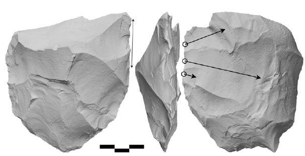
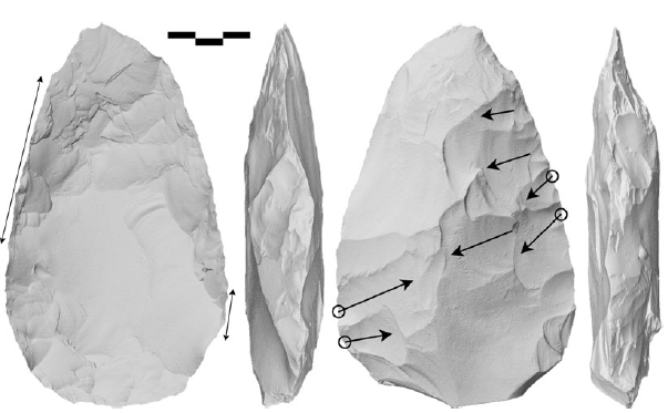
Turning-the-edge was documented on the butt of an unfinished handaxe, broken due to endshock (Fig. 3). Instances of finished handaxes with turning-the-edge undertaken in the last stages of flaking resulting in thinner tips were noted (Fig. 4). There were examples where turning-the-edge appeared to have been used to remove particular remnant lumps from successive step terminations or irregular cortical topography at a late stage of flaking (Fig. 5). The technique was also in evidence as a more general successive surface finishing strategy (Fig. 6).
The butt of an endshock broken handaxe with a turned edge from Boxgrove Q1/B unit 3 (#26). The section of edge with small scars raising the plane of intersection is shown by the double-ended arrow on the left and the invasive thinning scars with intact initiations are shown by the single-ended arrows emanating from open circles on the right. Scale in cm.

Boxgrove Q1/B handaxes #25 from unit 3 (above) and #114 from unit 4u (below) with turning-the-edge thinning the handaxe near the tip. Double-ended arrows on the left denote the portion of edge with small scars raising the plane of intersection and single-ended arrows on the right denote invasive flakes with intact initiations using the small scars as a platform. Note in both cases the raised plane of intersection near the tip in the profile view. Scale in cm.

Boxgrove Q1/B handaxes #181 (above) from unit 4/3 and #40 (below) from unit 3 where turning-the-edge has been used to remove large lumps in the last stage of flaking. Double-ended arrow on the left denotes the portion of edge with small scars raising the plane of intersection and single-ended arrows on the right denote invasive flakes with intact initiations using small steep-angled scars as a platform. Note the steep stepped scars on the lower side of handaxe #181 that would have left a large area of high topography prior to the large invasive flake. Note that the deep platform to strike the very large invasive flake on handaxe #181 has restored the plane of intersection to an equal position, but either side of this scar it can still be seen to have been raised to the invasively flaked surface. Cortical areas on #40 are shown in yellow. Note that the invasive scar passes through one of these areas but does not quite reach the other two. The nodule on which this piece was made must have been very irregular in shape and the knapper seems to have struggled with the convexities of the cortex on the left surface and the concavities of the cortex on the right surface. Scale in cm.

Handaxe #35 from Q1/B unit 3 with turning-the-edge used as a general finishing strategy. Double-ended arrows on the left denote the portion of edge with small scars raising the plane of intersection and single-ended arrows on the right denote invasive flakes using the small scars as a platform. Intact initiations are shown by open circles. Note the tranchet tip on this piece disrupts its outline. Scale in cm.

Turning-the-edge was sometimes directly linked with tranchet flaking (Figs 7 & 8). Due to the requirement of striking a large flake from a biface tip where the edge angle is typically low and there is relatively little volume of stone to strike into, turning-the-edge can both strengthen the platform and allow for an invasive flake to run across more of the tip.
Boxgrove Q1/B handaxes #185 from unit 4/3 (above) and #254 from unit 4 (below) where turning-the-edge was used in the detachment of the tranchet flake. Double-ended arrows denote the portion of edge with small scars raising the plane of intersection, single-ended arrows denote invasive flakes using the small scars as a platform. Intact initiations are shown by open circles. Note in both cases the raised plane of intersection at the tip in the profile view. Cortical areas on #254 are shown in yellow. In the case of #254 the knapper tried unsuccessfully to thin the lump of cortex on the right surface from a raised plane of intersection. The failure to remove this lump precluded final trimming of that edge which may be why the small facetting scars related to the tranchet removal have been left intact. Note the tranchet scar on this piece disrupts the outline of the tip. Scale in cm.

Boxgrove Q1/B handaxes #211 from unit 4/3 (above) and #272 from unit 4 (below) where turning-the-edge was used in the detachment of the tranchet flake. Double-ended arrows denote the portion of edge with small scars raising the plane of intersection, single-ended arrows denote invasive flakes using the small scars as a platform. Intact initiations are shown by open circles. Note in both cases the raised plane of intersection near the tip in the profile view. Note the tranchet scars on these pieces have disrupted the outline of the tip. Scale in cm.

Tranchet and standardization
Of the 326 complete handaxes, 81 per cent (n=265) had tranchet tips, with 44 per cent (n=144) having tranchet scars on both surfaces (Fig. 9). A chi-square test showed there was no relationship between blank type and whether handaxes had a tranchet tip (n=153, χ=0.632, p=0.427). Tranchet flaked handaxes had significantly lower scar density scores (mean=2.465) than non-tranchet handaxes (mean=3.076) (unequal variances t-test: t=3.912, df=72.167, p=0.001), indicating they are less rather than more reduced. Despite examples of tranchet scars disrupting the symmetry of the tip (Figs 6–8), there was no significant difference in bilateral (plan) asymmetry between tranchet and non-tranchet handaxes (unequal variances t-test: t=1.323, df=77.268, p=0.19). (Note that plan asymmetry was log transformed due to negative skew in the raw data.) However, tranchet handaxes did have significantly more irregular outlines than those without (equal variances t-test: t=3.692, df=324, p<0.001).
Examples of large double-tranchet handaxes with high values of PC1 from Boxgrove Q1/B unit 4/3. Handaxe #210 is above and handaxe #196 is below: see Figure 10 for where these fall along PC1. Arrows denote tranchet scars, with the open circle showing an intact initiation. Note that the three tranchet scars without open circles are truncated by other scars. Scale in cm.

A Wilcoxon rank-sum test showed no significant difference in the distance between homologous landmark points in cobble (n=119) versus flake (n=29) blank handaxes (rank-sum=21342, p=0.38). Wilcoxon rank-sum tests also showed no significant shape difference between handaxes from successive units in the Q1/B sequence: unit 3c (n=13) and unit 4u (n=62) (rank-sum=5428, p=0.37); unit 4u and unit 4 (n=143) (rank-sum=41682, p=0.71); and unit 4/3 (n=61) and unit 4 (rank-sum=40900, p=0.49).
The PCA analysis extracted five components each explaining more than 5 per cent of shape variability and totalling over half (52 per cent) of the variability. The first component (PC1) explained 21 per cent of variability and described a continuum from rounded, thicker handaxes (positive values) to elongate, thinner handaxes (negative values) (Fig. 10). The relatively low variability explanation score for this first principal component in comparison to other 3D geometric morphometric handaxes studies is likely because this sample is only reflecting variation within a single standardized assemblage, so there are not marked systematic shape differences across a single parameter of variation. The second component explained 11 per cent of variability and the fifth component explained 5 per cent, with both components describing tip asymmetry, positive values having right-skewed tips (when viewed from the more domed surface) and negative values having left-skewed tips. The third component explained 8 per cent of variability and described thickness, with positive values being thick and negative values being thin. The fourth component explained 7 per cent of variability and described tip shape, with positive values having broad, cleaver-like tips and negative values having pointed tips.
Scatter plot of the first two principal components for the Boxgrove Q1/B handaxes. PC1 explains 21 per cent of variability, PC2 explains 11 per cent. Models below show the axis of variation along PC1 from –5 to +8. Items are coded by tranchet flakes (0 = no tranchet flakes; 1 = tranchet on one surface; 2 = tranchet on both surfaces), with 90 per cent confidence ellipses shown for each group, and group centroids denoted by crosses. The reference line on the x-axis shows the median value for PC1 (–0.26). Handaxes 196 and 210 with high values of PC1 are shown in Figure 9.

Regression analyses were performed on PC1 to understand the drivers of the main parameter of shape variation. PC1 is in part describing an allometric relationship, with a weak (adjusted R square = 0.049) inverse correlation to volume (df=325, F=17.778, p<0.001), such that larger handaxes tended to be more elongate. The thinness element of PC1 suggests it is also describing knapping skill, with a weak (adjusted R square = 0.025) inverse correlation between PC1 and thickness-to-width ratio (df=325, F=9.31, p=0.002). Larger, more elongate handaxes (negative values of PC1) tended to be thinner relative to their width. Regression analysis of PC1 against scar density suggests there was also a weak (adjusted R square = 0.046) reduction component to PC1 (df=325, F=16.772, p<0.001), with more reduced handaxes being relatively rounder and thicker, perhaps as a result of resharpening reducing elongated tips without further thinning.
The distribution along PC1 shows left skew, with larger outliers having high positive values. The median value for PC1 shown by the reference line (Fig. 10) is between the values for the two tranchet samples and closer to the double tranchet group centroid. The size of the 90 per cent confidence ellipses for PC1 and PC2 (Fig. 10) suggests handaxes with a single tranchet tip are more standardized than those without, and handaxes with a double tranchet tip are more standardized than those with one tranchet.
Total assemblage variability as measured by distance between homologous landmarks to the group centroid was 5.12. A Wilcoxon rank-sum test comparing within group variability confirmed that handaxes without a tranchet tip (n=60, mean variability distance = 5.84) are significantly more variable in shape than those with one (n=123, mean variability distance = 5.23) (rank-sum=6336, p=0.01). Likewise, handaxes with a single tranchet tip (n=123) were significantly more variable in shape than those with a double tranchet (n=143, mean variability distance = 4.61) (rank-sum=16844, p<0.01).
Discussion
The lack of difference between nodule and flake blank handaxe shape at Boxgrove indicates that handaxe form resulted from an imposed mental template, in agreement with other analyses of the Boxgrove assemblage (García-Medrano et al. Reference García-Medrano, Ollé, Ashton and Roberts2019; Pope et al. Reference Pope, Wells and Watson2006). Previous geometric morphometric assessment has suggested that Boxgrove handaxes are particularly standardized (Shipton & White Reference Shipton and White2020), and the shape variability score of 5.16 in this study confirms this, with Boxgrove Q1/B being more standardized than five Levantine Acheulean assemblages that have undergone the same analysis (‘Ubeidiya (Early Pleistocene) 11.07, Gesher Benot Ya’aqov (early Middle Pleistocene) 6.52, Nahal Hesi (late Middle Pleistocene) 9.47, Ma’ayan Barukh 7.69 (late Middle Pleistocene) and Holon 9.58 (late Middle Pleistocene): Herzlinger et al. Reference Herzlinger, Varanda, Deschamps, Brenet, Lopez-Tascón and Goren-Inbar2021). The sample from the most standardized of these assemblages, Gesher Benot Ya’aqov, only included handaxes from a single material (basalt), blank type (flake) and layer (II6L4), so the greater standardization at Boxgrove, where there is variation in blank type, is noteworthy. The relatively low variability score for PC1 (21 per cent) may also be due to success in imposing a mental template at Boxgrove, with only limited influence of other factors on handaxe form.
As with other Acheulean assemblages, the particular average shape of the Boxgrove handaxes probably resulted from slow drift over multiple generations from an ancestral Acheulean form and conformity to the most common model within generations. However, the standardized form of the Boxgrove handaxes was not subject to random walks on the short timescale over which the sequence accumulated, with consistency in form between the successive stratigraphic units. This renders it unlikely that Boxgrove handaxe shape was down to the idiosyncratic preferences of an individual expert knapper, with such prestige bias likely overstated as a force in small-scale egalitarian societies in any case (Chellappoo Reference Chellappoo2021; Woodburn Reference Woodburn1982).
Flint is an excellent material for knapping in its ease of fracture and the sharpness of the edges it produces; however, the highly irregular lumpy form of flint nodules makes imposing a specific shape on them extremely challenging. The close adherence to a particular handaxe form at Boxgrove is thus unlikely to be purely the result of drift. The lack of relationship between blank types and tranchet tips indicates these are not incidental outcomes of manufacturing process. The overall standardization in combination with the tranchet tips on the Boxgrove handaxes suggests there is another factor governing handaxe form that sets Boxgrove apart from earlier Acheulean assemblages; prescriptive normative rules imposed at a cost to the individual knapper. The tranchet scars were struck both relatively early as well as at the end of reduction (Figs 1, 2 & 9), with tranchet handaxes having lower scar densities suggesting they are not more resharpened versions of non-tranchet handaxes. In fact, it is possible that some of the smaller, rounder Boxgrove handaxes are reduced versions of those that originally had tranchet tips. Tranchet scars are also pervasive, occurring on 81 per cent of Q1/B handaxes, with some of those without tranchet tips exhibiting failed attempts (Leroyer Reference Leroyer2016, 403–6). Tranchet tips are therefore a fundamental design component of the Boxgrove handaxes.
There was no correlation between tranchet flaking and asymmetry, probably because when tranchet flakes altered one lateral edge, the Boxgrove knappers mirrored this outline on the opposite edge (Fig. 11). Tranchet tips did however disrupt the outline of the tip (Figs 6–8 & 11), resulting in significantly more irregular outlines on tranchet pieces. This indicates tranchet tips were important enough to override other considerations of handaxe form (Leroyer Reference Leroyer2016). Tranchet flaking is also extremely difficult to execute, with a high risk of end-shock breakage of the entire handaxe (Fig. 3), something that 2 per cent of the Q1/B sample succumbed to, as well as a high proportion of the Q1/A assemblage. Moreover, 46 per cent of Boxgrove handaxes had double tranchet tips, meaning a very high risk of breakage for marginal functional gains. From this time onwards in the British Acheulean, distinctive and difficult-to-make handaxe forms characterize assemblages belonging to different periods and regions, such as handaxes with z-twists in their profiles, handaxes with elongated pointed tips (ficrons) and handaxes with one flat and one domed surface (planoconvex) (Ashton & Davis Reference Ashton and Davis2021; Bridgland & White Reference Bridgland and White2015; Shipton & White Reference Shipton and White2020; Wenban-Smith Reference Wenban-Smith2004; White et al. Reference White, Ashton and Bridgland2019). These handaxe sub-types, whose earliest manifestation in Britain is at Boxgrove, indicate a normative prescription to create distinctive and challenging forms.
Handaxes from Boxgrove Q1/B unit 4 showing regularization and marginal trimming scars on both surfaces that mirror the outline shape of previous tranchet scars removing the opposite edge of the tip, adapted from Leroyer Reference Leroyer2016. Short dashed lines show the axis of symmetry, long dashed lines show the inferred biface outline prior to the tranchet scar and subsequent flaking on the tip. Closed circles show intact initiations, open circles show the inferred locations of missing initiations. A = #203; B = #377; C = #295; D = #235. Note how the tranchet scars disrupt the previously regular outline of the handaxes. In specimen A the outline is already disrupted by a nodule break surface indicated by the thick diagonal lines, with the final scars also mirroring this surface.

Since tranchet scars result from a single forceful strike, they inevitably have less control than standard bifacial tip shaping and therefore reduce handaxe standardization in and of themselves, as borne out by the greater plan outline irregularity of tranchet-tipped handaxes at Boxgrove Q1/B. Despite this, single tranchet handaxes are more standardized in shape than those without tranchet tips, and double tranchet handaxes are more standardized again than single tranchet. This suggests that those more skilled knappers who were more successful in applying the normative rule of a tranchet tip were also better able to achieve the overall normative handaxe form for Boxgrove. This is exemplified by the median value for the main parameter of Q1/B shape variation (PC1) falling between the group centroids of single and double tranchet handaxes, with the centroid for non-tranchet handaxes farther away from the assemblage as a whole (Fig. 10).
The main parameter of shape variation at Q1/B describes a continuum from more elongate, thinner handaxes (negative values) to rounded, thicker handaxes (positive values) (Fig. 10). Consistent with previous findings for Boxgrove, this probably in part reflects greater reduction of the tip and sides when resharpening these handaxes (Shipton & Clarkson Reference Shipton and Clarkson2015b). A negative correlation between PC1 and handaxe volume indicates that the elongate, thinner handaxes were also larger, probably due to hand-size constraints (Crompton & Gowlett Reference Crompton and Gowlett1993; Shipton et al. Reference Shipton, Petraglia, Paddayya, Adams and Blades2009). Making thinner handaxes requires more knapping skill, so the negative correlation between PC1 and volume is consistent with a previous observation for Boxgrove that larger handaxes tend to be more skilfully made (Leroyer 2016, 357; Reference Leroyer and Klaric2018). This pattern is evident within Acheulean assemblages more generally, although the opposite pattern occurs between assemblages, with those having smaller handaxes overall tending to have relatively thinner handaxes (Shipton Reference Shipton2013; Shipton et al. Reference Shipton, Clarkson and Pal2013). Single tranchet handaxes typically have lower values for PC1 than non-tranchet handaxes, while double tranchet handaxes tend to have lower values than single tranchet handaxes. Unsurprisingly, given the difficulty involved in tranchet flaking, this trait thus appears to correspond with greater skill levels.
Tranchet flaking at Boxgrove sometimes involved the turning-the-edge technique (Fig. 8). Turning-the-edge was also evident in a variety of other situations in the Boxgrove Q1/B assemblage, including thinning the tip, removing large lumps from the centre, earlier stage thinning, and as a general finishing strategy (Figs 3–7). Examples of turning-the-edge also occurred in each of the four main handaxe-bearing stratigraphic units at Q1/B. This widespread use indicates it was not the prerogative of a single expert but something that was acquired by multiple knappers in the Boxgrove population. The general use of turning-the-edge explains why Boxgrove handaxes are the thinnest in the Acheulean world.
Conclusion
The tranchet imperative and the standardization of the Boxgrove handaxes, in particular those with tranchet tips, indicate social norms were a feature of hominin social life 480,000 years ago. Social norms are an essential ingredient in symbolic communication, as they allow for collectively understood meanings to be linked to arbitrary signals. That some form of symbolic communication was in use at Boxgrove is implied by the widespread use of turning-the-edge to create exceptionally thin handaxes, since transmission of this technique seems only to be possible in modern knappers using linguistic instruction to refer to specific opaque features of the process.
Early Acheulean handaxes may have been a reliable index of a particular activity (e.g. butchery) or place (e.g. a home-base) to which they were directly connected. From as early as Boxgrove, arbitrary styles suggest handaxes were taking on new social functions, perhaps acting as a reliable indicator of behavioural synchrony (Rossano Reference Rossano2010; Shipton et al. Reference Shipton, Nielsen, Di Vincenzo, Killin and Hermansson2021; White et al. Reference White, Ashton and Bridgland2019). The utility of the normative tranchet tip means it might only have been an implicit norm among functionally equivalent alternatives (Sackett Reference Sackett1982). However, the difficulty in achieving the form and the variety of stages at which it was introduced suggests it was not simply a sub-consciously reproduced particular style, but that this sub-type of handaxe was a named concept (cf. Pelegrin Reference Pelegrin2009) in the minds of the Boxgrove knappers. By the end of the Acheulean in Britain, the appearance of skilfully made but functionally deficient giant handaxes seems to reflect hominins using these objects as explicit symbols as a primary purpose (Dale et al. Reference Dale, Rawlinson and Knowles2024; Khaksar & Modarres Reference Khaksar and Modarres2024).
Boxgrove handaxe form was governed by collectively understood rules, while the social transmission of the knapping process likely required specific signals to direct attention to subtle elements embedded deep within a complex hierarchical process. These lines of evidence suggest symbolic precision in communication, i.e. lexicon, may have emerged in the hominin behavioural repertoire by half a million years ago.
Acknowledgements
The Boxgrove excavations were directed by Mark Roberts and Simon Parfitt. We are grateful for the accession of the material to the British Museum for general access. We thank Matt Pope for discussions of the Boxgrove stratigraphy and comments on a draft of this paper. Three anonymous reviewers provided constructive comments which were used to improve this article. This research is funded by the AHRC project ‘Digital Technologies, Acheulean handaxes and the Social Landscapes of the Lower Palaeolithic’ (AH/W009951/1).


 Open access