


1. Introduction
CAD systems are rarely used for early form creation, but they are ultimately used to generate a 3D form of a design that needs to be manufactured. The definition of the form itself is usually done during conceptual design stage, and activities performed in their definition are dependent on the individual designer preferences (Reference Takala, Keinonen and MantereTakala et al., 2006). It is a complex and time-consuming endeavour to master most commercially used CAD systems (Reference Bodein, Rose and CaillaudBodein et al., 2013). The learning curve is steep, and new users find the process of using the mouse and keyboard in a 2D environment to design a 3D object tedious, lengthy and unintuitive (Reference Dave, Chowriappa and KesavadasDave et al., 2013). They are based on sequential activities a system can perform (Reference Stark, Israel and WöhlerStark et al., 2010). Even when procedures and processes are adopted by the users, some design activities such as free-form spline modelling (used to design complex irregular shapes), require manipulation of splines via many control vertices, which can be a difficult and time-consuming process (Reference Gao and GibsonGao and Gibson, 2006). Modern requirements require modern solutions, enabling faster design development and lowering barriers to entry for new designers (Reference FrazelleFrazelle, 2021).
The ability to generate or modify a design at a pace that matches the designers thinking processes can be more important than the focus on detail (Reference Fuge, Yumer, Orbay and KaraFuge et al., 2012). Use of CAD is known to lead to circumscribed thinking limiting the design to the capabilities of the tools used in its creation (Reference Robertson and RadcliffeRobertson & Radcliffe, 2009). Bounded ideation happens when designers’ focus is diverted from thinking about the ideation and form creation to thinking about commands and procedures used in CAD that enable the designers to create a specific shape (Reference HuangHuang, 2007; Reference Robertson and RadcliffeRobertson & Radcliffe, 2009). It is possible that dual-process theory could provide explanation for some of these issues by observing different types of cognitive processes supporting design. Dual-process theory proposed that there were at least two major types of cognitive processes (Reference Evans and StanovichEvans & Stanovich, 2013) present in design; Type 1 that is intuitive and fast associated with intuitive rapid responses, and Type 2 that is analytical, deliberate and slow, used during deliberate analysis and reflection. Each is likely to be dominant in a specific phase of a design activity, but in general they act in conjunction across the design task as a whole (Reference Cash and MaierCash & Maier, 2021). It is believed, although it is yet to be fully tested, that when representation mode of an input and response are matched Type 1 processing occurs, and when they are mismatched Type 2 processing is required to interpret and manipulate the input (Reference Evans and StanovichEvans & Stanovich, 2013). It was identified that the length of gaze can be an indicator of Type 2 processing depth and engagement (Reference Purcell, Howarth, Wastell, Roberts and SwellerPurcell et al., 2022). Matched input and representation via gestured input led to a more complete and accurate reproduction of a communicated concept and prompted a focus on spatial and dynamic features of a concept, while still enabling the designer to perform the key objective of the design activity (Reference Cash and MaierCash & Maier, 2021). Dual process theory is just beginning to be established in the design field (Reference Cash, Daalhuizen, Valgeirsdottir and Van OorschotCash et al., 2019; Reference Lawrie, Flus, Olechowski, Hay and WodehouseLawrie et al., 2024) and its methodological application presently relies on coding data collected during a design activity, interpretation of the results by the researchers that are used as a basis for model building or drawing conclusions about the design process (Reference Gonçalves and CashGonçalves & Cash, 2021).
Commercially available CAD systems rely on a menu-based WIMP (Window Icons Menus Pointer) interfaces (Reference Sharma, Madhvanath, Shekhawat and BillinghurstSharma et al., 2011), which are complex and not suitable for form creation (Reference Fuge, Yumer, Orbay and KaraFuge et al., 2012). Systems enabling 3D modelling have been exploring improved interaction interfaces, focusing on the ability of designers to input information or control the system. Majority of these systems use hand gestures as a sole or one of the interaction modalities. One of the earliest solutions was a system where free-form gestures were used to create non-standard shapes, and a combination of predefined hand positions and voice commands were used to create standard shapes (Reference Dani and GadhDani & Gadh, 1997). More recent developments focused on free form gestures supplemented with symbolic gestures or other modalities of interaction (speech or pressing a button) that were used to manipulate or modify objects in 3D, VR or AR environments. In some of these applications, shapes were created by drawing a profile that was then swept in space along a path and further modified using free-form or parametric deformation and manipulation (Reference Murugappan, Liu and RamaniMurugappan et al., 2013; Reference Huang, Jaiswal and RaiHuang et al., 2019). Some used free-form gestures for surface creation, by tracing the motion of the hand and transforming that path into a spline or a part of a surface (Reference Qin, Wright, Kang and PrietoQin et al., 2006; Reference Holz and WilsonHolz & Wilson, 2011). Maturity of these systems and interaction modalities was varied, and none are fully accepted in the design community or implemented in daily activities of designers. The novelty of these solutions is primarily in the field of interaction with the system, rather than the design process itself. While the activities that can be performed using the chosen mode of interaction have been considered to some extent, and either follow the parametric solid modelling workflow or lean towards digital sculpting, the workflow itself was not a major consideration in the research performed.
This paper explores potential characteristics of a CAD system that would align with the nature of design and be less limited by the capabilities of technology that was historically used. It aims to provide more information on what activities could be added to form creation workflow designers using new interfaces might be following in the future, without imposed limitations of current technology. If a new interface enabling use of natural and intuitive gestures in VR/AR becomes a reality, could a fresh look also be taken at the nature of form creation to align it better with the nature of design process? It is also possible that type of thinking required for creative form exploration and type of thinking required to follow procedural nature of CAD systems clash, and do not always lead to the improvement of the design process. These questions are explored via a study performed to compare traditional ways of working, following a sequence typically used during solid model creation in a CAD system, with completely open-ended creation of a model, utilising hand gestures as an interaction modality, aiming to explore if established procedural rules used in CAD systems should be carried over into future systems.
2. Method
Gesture input modality observed in the study reported in this paper is partially inspired by the need to match up the spatial and dimensional nature of form creation in 3D and the gesture input modality, and findings that matching up input and representation brings benefits to the design process. The study focuses on comparing the guided and free design process, both using gesture-based interaction.
2.1. Study steps
Participants in the study were placed in front of a screen displaying shapes they were asked to create or manipulate using their hands, and their responses were recorded using two cameras placed under the screen in front and to the left of the participant (see Figure 1). There were 44 participants (29m, 15f), product design engineering students in their penultimate and final year of studies, or recent graduates. “Mature” students were chosen as they can be considered advanced beginners or novice designers (Reference Liikkanen and PerttulaLiikkanen & Perttula, 2009), as they have the key characteristics of designers but have not yet fully adopted all established design workflows. On average they had 4.9 years of CAD experience, and 1.4 years of design experience in the professional environment, including internships. Typically, they have spent at least three years working on student projects with industry involvement. They have displayed the spatial perceptions skills, creativity and concept manipulation throughout their training. This made them a good compromise between experienced designers heavily influenced by previous experience (Reference Piumsomboon, Clark, Billinghurst and CockburnPiumsomboon et al., 2013) and general public that may not be able to tackle niche conceptual design problems, and ensured data collected is representative of designer skills and needs. Seven participants were left-handed, 33 right-handed and one participant was ambidextrous. Requirement for approval was waived by the institutional ethics committee, as the activities were deemed appropriate.
The screenshot of one of the participants taking part in the study (front view on the left, side view on the right)

The study had two stages, illustrated in Figure 2.
Visualisation of the study stages

Time was unlimited, and participants were shown images of objects they were asked to create. In Stage 1 participants were shown images at different stages of completion and asked to propose how they would create the form shown in each of the steps. This stage is considered guided as the forms created followed a traditional CAD workflow. In Stage 2 participants were shown the complete object and asked to create it, with only guidance being they were to imagine they were creating a shape in a 3D environment in front of them, and that it does not have weight. Stage 2 is thus considered unguided in terms of workflow. Steps in Stage 1 were introduced to ensure data is collected even if participants skip a number of steps in the unguided Stage 2.
The study was allowed to continue uninterrupted if the participants moved through it on their own well. Where needed they were prompted, but prompts were limited to reminders about the steps (e.g. “Note that the edge is filleted – how would you do that?”), and not instructions on how to do them. Some participants asked about the nature of the objects e.g. “should I imagine that this is on the table?”, and the response would be that whatever the object appears like to them was the accurate way to perceive it.
Half of the participants performed the two stages of the study in reverse, to reduce the chance they would unconsciously learn steps to perform in the stage 2 if they all performed stage 1 first. This could have been avoided by using different participants in two stages of the studies, but that approach would reduce the ability to compare reactions of same participants across both parts of the study. Hence, the possibility of some percentage of the participants being influenced by time limitations was accepted.
Gesture identification was done using manual coding by the first author and 10% of the sample was coded by two additional coders that randomly selected 10% of the sample. Gestures and coding will not be discussed in this paper as the focus is on activities, but gestures were analysed in detail and published in a separate paper (Reference Vuletic, Duffy, McTeague, Hay, Brisco, Campbell and GrealyVuletic et al., 2021).
3. Results
Each participant created two different objects, and due to the combinations of objects and the number of participants, the number of times a specific object was created overall varied slightly. Final numbers were not identical across the two stages, but they were in the comparable ranges as shown in Table 1.
In two sequences entire steps were omitted, and what was described would not have resulted in a full product displayed in the image shown to the participant. Both instances occurred in the free creation stage, and while narrating their actions participants they were interacting with elements on the screen they previously did not “complete”, so it is possible that those participants overlooked some of the steps. These sequences were omitted from the data.
Number of different objects created in each stage

3.1. Cup creation workflow
The sequences of activities are graphically illustrated in Figure 3. In the majority of cases, a cup was created by first either extruding (in 26 instances) a circular profile into a cylinder or sculpting a cylinder (in five instances), then ”shelling” that cylinder (i.e. retaining the walls and bottom of the cylinder but removing the top surface and the volume on the inside) and adding the handle. The form of the handle was different for the two variants, and that was noted in the classification tables. Sequences including extrusion and a traditional handle were classified as CV1 and those with extrusion and spherical handle as CV3. Sequences including sculpting and a traditional handle were classified as CV2 and those with sculpting and spherical handle as CV4. In the free stage, one additional workflow emerged, classified as CV5. In it, a larger and a smaller circle were drawn in the same plane and then extruded to different heights to form the body of a cup. Then the handle was added.
Sequences for cup creation

3.2. Phone casing creation workflow
For the phone casing (shown in Figure 4) and the hexagonal plate (shown in Figure 5) different workflows from those suggested in guided workflow started to emerge. While in the guided stage all instances of phone creation followed the same workflow (classified as PV1), in the free stage three workflow variants appeared (classified as PV2, PV3, PV4). One to two participants performed each of the alternative workflows (five in total), while 14 participants overall performed the sequence classified as PV1.
Sequences for phone cover creationx

Figure 4 Long description
Panel 1: A sequence of steps for creating a phone cover. The steps include drawing a rectangle, extruding it, creating a shell, filleting the edges, drawing an offset, and extruding a cut. Panel 2: Another sequence for creating a phone cover. The steps include making a rectangular block, creating a shell, filleting the edges, and extruding a cut. Panel 3: A different sequence for phone cover creation. The steps include drawing a rectangle, creating edges, filleting the edges, extruding edges up, drawing a rectangle, and extruding a cut. Panel 4: A sequence involving drawing a rectangle and an offset, extruding to different heights, and extruding a cut.
Sequences for hexagonal plate creation

3.3. Hexagonal plate creation workflow
For the creation of the hexagonal plate (shown in Figure 5), the difference between the guided and free activities was the largest. In the guided stage, three variants appeared (HV1, HV3 and HV6). In the free stage an additional five variants emerged (HV2, HV4, HV5, HV7 and HV8). HV1-6 employ manipulation of shapes using bending of sheets similar to that of sheet metal forming, we will refer to as forming. There were two variants of the hexagonal plate, used to uncover the gestures proposed for a creation of a cube in the context of a product. However, in terms of activity sequencing only, the creation of the hexagonal plate without the stand is observed in both instances.
4. Activities introduced to the workflow by use of gestures
The majority of the sequences for the creation of the cup and the phone cover followed the steps that would have been followed if objects were created as solid parts using CAD (CV1/3, CV5, PV1-4, HV1, HV4, and HV7). In one sequence for the cup creation (CV2/4), to create the cylinder and the smaller cylinder that later became the cup handle, the parts were “sculpted” (“roll into cylinder”). When the hexagonal plate sequences were analysed, it was noticeable that a larger proportion of them included “sculpting” activities (HV3 “Push the middle down”, HV8 “Pull each side out”) or “forming” activities (HV2 “Bend the edges”, HV5 “Cut a hexagon” and “Weight down the centre and bed the edges”, HV6 “Bend the triangle”). In other words, they included manipulation of imaginary surfaces that resembled activities that would have been performed in physical reality, rather than creation of shapes using planes, surfaces and lines.
Participants were instructed to assume dimensioning would have happened automatically (“the room would know what size they want something to be”), hence the details such as sizes and distances, or omission of assigning thickness to surfaces were not considered while analysing the sequences. Thus, likely influenced by this instruction, bending a triangle was often performed assuming that both sides would remain flat surfaces. In conceptual design, the goal was to convey the idea rather than the details. Hence, the assumption those geometrical definitions would remain while “sculpting” the elements was assumed valid in this study.
Figure 6 provides an illustration of number of participants that performed the design sequences in a guided manner or free manner, for each of the object variants, in the right half of the figure. Blue squares indicate a participant that performed a guided sequence, yellow squares indicate a participant that performed a free sequence. It is noticeable that a larger number of variants occur during the performance of the free sequences, 16 compared to 8 guided sequences. These sequences also introduce steps that do
not match the guided steps and instead include sculpting activities such as extrusion by pulling or forming activities such as bending. This may suggest that the current workflows used for solid modelling are perhaps not the most intuitive when users are interacting with a 3D object in a 3D environment. On average, the number of gestures performed during each sequence step is on average between 7 and 12 for the guided sequences, and between 5 and 7 for the free sequences.
Left half of Figure 6 illustrated number of sequence steps for each of the variants. The number of sequence steps is also lower for the free sequence workflows, 4.5 on average for free sequences and 5.9 for guided. This may suggest that the established guided sequences are perhaps not the most effective either. The need for increased number of gestures for established solid creation sequences may stem partially from the definition of the workflow reliant on the need to account for exact dimensions, which is something that has not been considered in this study. However, the dimensions were not set even for guided workflows, so there has been some normalisation of data in those terms, as to finalise the shapes the activities in both free and guided sequences would need to be dimensioned. Sequence steps that include elements of sculpting are illustrated by the circle placed in the middle of a box indicating a sequence step, those including elements of forming are illustrate by a triangle. Interestingly these appear in both free and guided sequences in roughly equal measures (7 in guided or both free and guided, and 6 in free only). The sculpting occurrence is particularly prominent during the creation of the hexagonal plate and could be linked to the complexity of the activities that would have been needed to be performed in a CAD system to create such a shape. During the creation of the cup and phone case, the planes used were parallel or perpendicular, and the shapes used were predefined in most commercial CAD systems.
During the creation of the hexagonal shape, in which edges were angled at 30 degrees, creation of additional planes positioned through specific points in space would be needed or use of more complex commands. Participants were expected to have less experience with more complex commands, and to have more difficulty visualising shapes where planes were coinciding at different angles than 90-degree increments. The findings seemed to support this, as out of the eight fully compliant outcomes for the hexagonal plate, five have used sculpting or forming. This may indicate that current workflows could be augmented for shapes where bending or sculpting paradigms could serve as a quicker and more easily definable command (especially if gestures were used as an interaction modality).
Visual representation of numbers of participants and variants they performed, free or guided, including sculpting or forming paradigms

Figure 6 Long description
A matrix showing the number of participants and the variants they performed, including free or guided tasks with sculpting or forming paradigms. The matrix has 12 columns and 22 rows. Columns represent the number of participants that performed the sequence, ranging from 1 to 12. Rows represent the number of sequence steps, ranging from 1 to 8. The matrix uses color coding to indicate different types of tasks: green for free, blue for guided, and a combination of green and blue for tasks that include both free and guided. Circles and triangles are used to indicate tasks that include sculpting or forming. Notable trends include a higher number of participants performing guided tasks with fewer sequence steps, and a mix of free and guided tasks with more sequence steps. Specific sequences and the number of participants performing them are also highlighted.
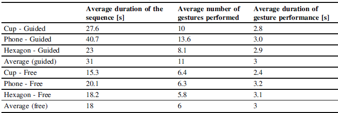
It is also noticeable that the workflows including “sculpting” and “forming” based activities took less time to complete. Table 2 shows average duration of workflow sequences per object per type of workflow (guided or free), average number of gestures performed and average duration of gesture performance. However, if the average durations of gesture performance are observed, they are quite consistent ∼3s (2.4 - 3.2s), while the average number of gestures performed is higher for the guided sequences. Average number of gestures performed in guided sequences is almost doubled, 11 gestures for guided sequences versus 6 for free sequences.
Observed per object, the largest difference is observed in number of gestures used is for the phone creation, where in free stage number of steps was reduced on average by 54%, followed by cup creation where number of steps was reduced by 36%, and lastly hexagonal plate creation where the reduction was 28%. But looking at the nature of activities performed in the phone cover creation, none of the gestures introduce “sculpting” or “forming” activities that are fundamentally different than the ones in the existing workflows. What does happen is that participants, given the chance, omit thinking about creation of supporting geometry they would need to think of using WIMP, as this allows them to focus fully on shape creation. This reduction in number of steps is also not entirely representative of the number of steps that would be necessary if these shapes were created in CAD using WIMP, as using gestures to input both of these workflows is conceptually using much lower granularity than realistic interaction with existing CAD requires. If we take into account the number of distinct steps required to input these activities into a software using WIMP, each of these gestures could potentially include a much higher number of activities needed to create supporting geometry required to perform an activity. For example, to create a rectangle you either need to sketch each side, click to close the shape; or pick a rectangle, and click on a plane you need to place it in. Using a gesture, you would trace the shape, which has the potential to make the process faster. However, how this is practically communicated to the software with enough precision, i.e. specifying exact location the traced shape should be in and specifying its scale in relation to existing space/elements in it, still requires standardisation and extensive amount of work. Looking at the creation of cup handle, if WIMP controlled CAD was used, a user would need to create a plane that fully intersects with the cup wall, draw the profile of the handle in it, create a plane that the spine of the handle would be drawn in, draw the spine, and then select profile and spine and loft it. Each plane creation could entail multiple steps. In the free workflow proposition was to roll a cylinder, bend it and stick it on. Practically the latter would require more intermediary steps or algorithms applied to constrain the details, however observing the nature of 3D shapes the free workflows introduced, they match the representation better and require less cognitive manipulation of the three-dimensional objects. Similar applies to the hexagonal plate creation. To create sides of the plate from the hexagonal base, a plane needs to be created at a specified angle to create a spine of the loft. If sweep command needs to be used, because we want a specific profile in the end plane, additional two steps are needed, an additional plane and end profile creation. If hand gestures are used to sculpt shapes instead, that match the spatial nature of the shapes themselves and interactions with that space, this would be expected to result in a quicker creation process, following Type 1 thinking. This is not reflected in the duration of gestures, as duration of gestures was consistent for activities in free and guided stages. But where the tasks performed during sculpting and forming activities are aligned to the spatial form of the shapes being created, they could potentially be explored for inclusion in existing CAD systems to reduce cognitive load on users and reduce the need for creation of supporting geometry that requires Type 2 thinking, strategic and time consuming. Using hand gestures rather than a WIMP interface could allow the focus on the form and spatial aspects.
Comparison of durations of workflow sequences, number of gestures and duration of gesture performance

There are practical barriers to account for when inclusion of new interaction interfaces is considered. For one, CAD systems currently used are very mature and highly embedded in industrial practices. Introduction of an entirely new interaction system fundamentally changing design workflows would potentially not be welcome, as it would be too disruptive. However, granular embedding of sculpting and forming paradigms where they could save work which goes into the creation of helper geometry could be considered in medium term CAD software development for activities such as lofting and sweeping shapes that currently require significant number of steps and more importantly creation of strategy around where supporting geometry needs to be created and how. If this could be automated so that the user can specify the key parameters, as the users in the study have, while the software takes over the practical creation of the shape, this could lead to a better experience for the users and reduction in workflow duration as less steps would need to be completed by the user.
5. Limitations of the research
Experiment setup of the study did not allow participants to focus on details e.g. set dimensions or position features accurately. While this is generally not the key characteristic of the conceptual design, some participants noted that they might have acted differently if they were required to be more precise or dimension objects. This should be considered for future activities. Additionally, only three objects were observed at this stage. Since the activities were highly dependent on the form of the objects, the inclusion of a wider variety of distinct shapes of different level of complexity would provide more robust findings and enable the researchers to identify more systematic future CAD systems requirements.
While majority of the participants (39 out of 44) stated that they did perceive objects as if they were 3D, although they were shown to them on a 2D screen, indicating that the results were valid, it may be interesting to perform the same study in a more immersive environment and compare the findings. As participants imagined the objects, majority did not feel the need to manipulate them between different activities (rotate or translate them), and this meant that the data on manipulative gestures within a design sequence had not been collected. Manipulation of 3D objects in a CAD system significantly affects its usability and should be explored in the future.
Finally, not all of the participants created the shape fully to the specification. For example, when creating a phone casing in the free stage out of 11 participants 3 did not define the shape being cut out of the side of the casing, reducing the pool of sequences to analyse for that particular activity. While this is not a major disadvantage in terms of exploring the general sequencing of activities, it would become significant in later stages of the research and any future studies should either test the perception of the objects by the participants prior to the study or include prompts if certain key steps are missed.
6. Conclusion
A study reported in this paper is focusing on the comparison of the gesture-based object creation workflow constricted by the capabilities of current CAD systems following the solid creation workflow and one giving users freedom to perform any activities they found appropriate. It was found that in the free creation stage participants often diverged from the procedural sequence that would have been followed if the shape were to be created in a CAD system. Interestingly even in the free creation stage some participants followed the typical CAD workflow but attempted to embed sculpting or forming inspired activities within certain steps those workflows. This was particularly prominent when the shape to be created required a more complex workflow to be followed when using CAD, i.e. contained surfaces that were not perpendicular to each other or shapes that were not standard, requiring creation of various places and supporting geometry. Given the chance to imagine a creation of forms using gestures, participants suggested workflows that would not be possible to achieve effectively using WIMP but have the potential to be useful if gestures were to be used as an additional form of interaction with the system. This would not be a simple proposition, as it would result in a disruption of highly mature processes followed in much of the industry. However, such a system may benefit from the introduction of granular elements into the existing workflows, for example using gestures introducing sculpting or forming approach to shape creation, instead of lofting or sweeping commands requiring additional supporting geometry creation typically used in current solutions. While proving this requires further exploration, these changes could align the natures of representation and activities performed, potentially reducing cognitive load on the users of these systems.
Acknowledgement
This research received no specific grant from any funding agency in the public, commercial, or not-for-profit sectors.






 Open access

