


Nomenclature

Subscripts
- conv
-
convection
- cool
-
coolant
- res
-
reservoir
- bat
-
battery
Greek Symbols

Abbreviations
- CDTO
-
cold day takeoff
- CHEX
-
compact heat exchanger
- CP
-
cold plate
- CTMS
-
centralised thermal management system
- ECS
-
environmental control system
- EGW
-
ethylene glycol water mixture
- EM
-
electric motor
- EPS
-
electrical power system
- DTMS
-
decentralised thermal management system
- HEX
-
heat exchanger
- HDTO
-
hot day takeoff
- LH2
-
liquified hydrogen
- LHT
-
liquid hydrogen tank
- PAO
-
polyalphaolefin
- PGW
-
propylene glycol and water mixture
- PMAD
-
power management and distribution center
- TMS
-
thermal management system
Trade Names
- Pycharm
-
programming environment
- Python
-
programming language
1.0. Introduction
The aviation sector is responsible for approximately 5% of anthropogenic causes of climate change. In this direction the Advisory Council for Aviation Research and Innovation (ACARE) has set a goal to reduce the CO2 by 75% for each passenger per kilometer, as well as the reduction of NOx and noise emissions by 90% and 65% respectively, by the year of 2050 [Reference Rao, Yin and Werij1, Reference Epstein and O’Flarity2]. This is the driving force to research the exploitation of alternative energy sources to supply hybrid propulsion concepts, such as electric energy, liquified hydrogen (LH2) and liquified natural gas.
Electric propulsion architectures are classified into all electric, hybrid and turboelectric [Reference Nasoulis, Protopapadakis, Ntouvelos, Gkoutzamanis and Kalfas3, Reference Gkoutzamanis, Kavvalos and Srinivas4]. All electric aircraft employ batteries for thrust generation, which limits their range due to the inherent limitations of reduced gravimetric energy, compared to the jet fuel counterpart [Reference Voskuijl, Van Bogaert and Rao5]. Hybrid electric configurations use gas turbine engines for propulsion and to charge batteries. They can be classified into parallel, series and series/parallel partial hybrid layouts. On a parallel configuration either or both the battery powered motor and the gas turbine can provide propulsive power. Parallel hybrid configurations have been extensively studied in the literature, with applications on commuter and regional classes [Reference Clark, Shi, Gladin and Mavris6–Reference Lents, Hardin, Rheaume and Kohlman11]. Their apparent benefits include easier implementation, reduced complexity and costs, compared to the other variants. Series hybrid configurations, on the other hand, allow for the decoupling of electrical and thermal propulsors and enable novel configurations based on distributed propulsion. The generator driven by the gas turbine provides power to the motors and charges the batteries. The series/parallel architecture has either one or more fans which can be driven by a gas turbine (GT) while other fans are driven exclusively by electrical motors. The series architecture is normally an enabler of distributed propulsion concepts [Reference Fefermann, Maury, Zarati, Salanne, Pornet, Thoraval and Isikveren12]. In this direction, turboelectric propulsion also explores the benefit of distributed propulsion, which reduces aerodynamic drag [Reference BROWN13–Reference Perullo15]. It is based on a GT linked with a generator which then powers electric motors (EMs), and can be characterised as fully turboelectric and partial. Partial turboelectric propulsion, a portion of propulsive power is produced using electric propulsion, while the rest is produced by a GT. In addition, the use of cryogenic fuels is researched, such as LH2. However, this configuration poses a challenge as the voluminous cylindrical fuel tanks need to be accommodated.
As mentioned above, electric propulsion components do not employ a natural exhaust system like GT engines. Therefore, a thermal management system (TMS) must be incorporated to sufficiently cool electric compartments, but it is of primary importance to be as light as possible to minimise its integration impact on the aircraft. To design the TMS, a suitable working medium must be selected [Reference Affonso16–Reference Freeman, Osterkamp, Green, Gibson and Schiltgen18], including ram air. Architectures utilising air are deemed simpler and safer [Reference Schnulo19]. To improve their efficiency, added ducting could be used, cooling each compartment individually. Moreover, heat sinks could be applied on the compartments, to further benefit from the air convection. Furthermore, liquid working medium could be utilised, such as water, water and propylene glycol (PGW), or ethylene glycol, or glycol mixtures [Reference Kellermann, Lüdemann, Pohl and Hornung20–Reference Gkoutzamanis, Tsentis, Valsamis Mylonas, Kalfas, Kyprianidis, Tsirikoglou and Sielemann22], polyalphaolefin (PAO) [Reference Chapman, Hasseeb and Schnulo23, Reference Abolmoali, Donovan, Patnaik, Mccarthy, Dierker, Jones and Buettner24] and jet fuel [25]. These thermal management architectures provide high efficiency but also high integration impact, and are classified as centralised and decentralised. In centralised systems, the compartments are cooled via a central heat exchanger (HEX), while in decentralised systems individual cooling loops are designed for each compartment. Centralised systems feature either a series architecture or a parallel. In a series architecture all the environmental control system (ECS) compartments are cooled successively, which leads to some compartments being cooled by higher temperature liquid. On a parallel architecture, different loops are designed to cool a ECS compartment or a group of compartments which are then all connected in parallel. To further improve heat transfer either puller fans or a Brayton cooling cycle can be applied [Reference Brelje, Jasa, Martins and Gray26]. In addition, phase change materials (PCMs), such as Mg, Urea-KCL [Reference Shi, Sanders, Alahmad, Perullo, Cinar and Mavris27], can be attached to the external surface of a battery stator, as they feature measurable latent heat. Furthermore, in lighter aircraft surface heat exchangers can provide the same magnitude of cooling with a conventional TMS [Reference Kellermann, Habermann and Hornung28].
Li-ion type batteries introduce significant temperature sensitivity. In low temperatures, (below −10°C) they present charging resistance, whereas at temperatures higher than 40°C, their power is depleted [Reference Wu, Wang, Wu, Chen, Hong and Lai29]. Also, differentiation in temperature distribution above 5°C, alters their electrochemical efficiency. Consequently, their cold plates (CPs) design is investigated. In some cases, CPs could feature micro-channels to increase heat transfer. Furthermore, placing the CPs on their smaller latent surfaces, renders them lighter and more economic [Reference Sheng30]. To achieve more effective cooling, separate cooling loops for batteries can be designed, even with different liquid medium such as silicone (PSF-5), PCMs or water mixture with AL2O3 nanoparticles [Reference Zhi31, Reference Yetik, Yilmaz and Karakoc32]. This mixture features high heat transfer efficiency.
As the majority of research focuses mainly on parallel-hybrid configurations [Reference Rendón, Assato, Martins, Hallak, Altgott, Graça, Landy, Oliveira and Delmonte8–Reference Lents, Hardin, Rheaume and Kohlman11], the motivation of this work is to explore the preliminary design of a TMS considering a series propulsion architecture. Different thermal management architectures are examined, by altering the number of the system’s heat exchangers. Comparing these architectures for a set propulsion design, enables the selection of the most efficient solution, while allowing to examine the novel concept of applying the simpler, series propulsion architecture on hybrid electric propulsion systems. To achieve the goals of this study, a low-fidelity thermal model is developed. The model is capable of sizing the heat exchangers and calculates the temperatures and required coolant mass flows for each point of the system. For the analyses executed, the cooling medium selected is water and propylene glycol mixture 50% (PGW50). Furthermore, the weight of each model as well as their respective compartments are calculated.
2.0. Methodology
2.1. Propulsion configuration and assumptions
The propulsion architecture is based on one of the configurations developed in the Clean Sky 2 European project HECARRUS (Hybrid ElectriC smAll commuteR aiRcraft conceptual design). The aircraft is designed to carry up to 19 passengers and executes small range flights, employing technologies applicable by 2030 and beyond. The selected propulsive architecture features a series hybrid configuration, and it is illustrated on Fig. 1. The propulsive layout is composed of four electric motors, two on each wing. The gas turbine is embedded in the aft part of the aircraft’s fuselage. It is exclusively connected to the generator and is assumed to provide approximately 1,100kW of power. The generator is connected both with the batteries and the power management and distribution system (PMAD) in order to drive the motors. The batteries, which provide 1,600kW of power, are also linked with the PMAD, to provide propulsive power to the motors. The motors’ power is 600kW, so the electrical power system (EPS) produces 2.4MW of power.
Propulsion architecture schematic.

The mission executed by the aircraft is constituted by the following segments: taxi-out, takeoff, climb, cruise, descend, landing and taxi-in. Batteries supply propulsive power during takeoff and climb. Additionally, they should contribute supplementary power in case of a motor failure. During cruise, the batteries can be charged with the generator’s surplus of power. The TMS is designed during the mission segment where the higher thermal loads are expected, and therefore the EPS’s function is exacerbated. In the context of this paper this occurs during takeoff, and the functional parameters of each compartment at this point are presented on Table 1. The lower temperature limit constraint is enforced by the Li-ion batteries that must function at 40°C.
The TMS development relies on two axes: (1) provide sufficient cooling of EPS compartments to ensure safe function and (2) enable lightweight design. The working medium selected must fulfill certain criteria as following:
-
i. Good thermophysical properties: high thermal conductivity, low freezing point and explosion point for safe storage.
-
ii. High boiling point, low freezing point and bursting point for safe storage.
-
iii. Thermal and chemical stability.
-
iv. High life expectancy without the need for added chemicals.
-
v. Non-corrosive.
-
vi. Environmentally friendly, nontoxic.
-
vii. Cost effective and vastly available.
-
viii. High autoinflammation point.
Considering the requirements above, a qualified working medium is the propylene glycol mixture. In this respect, the fluid selected is a propylene glycol and water mixture, with 50% mix ratio. About the TMS architecture, two layouts are developed to compare their integration impact on the aircraft: a centralised as well as a decentralised arrangement.
Compartment thermal limits, power outputs and thermal loads

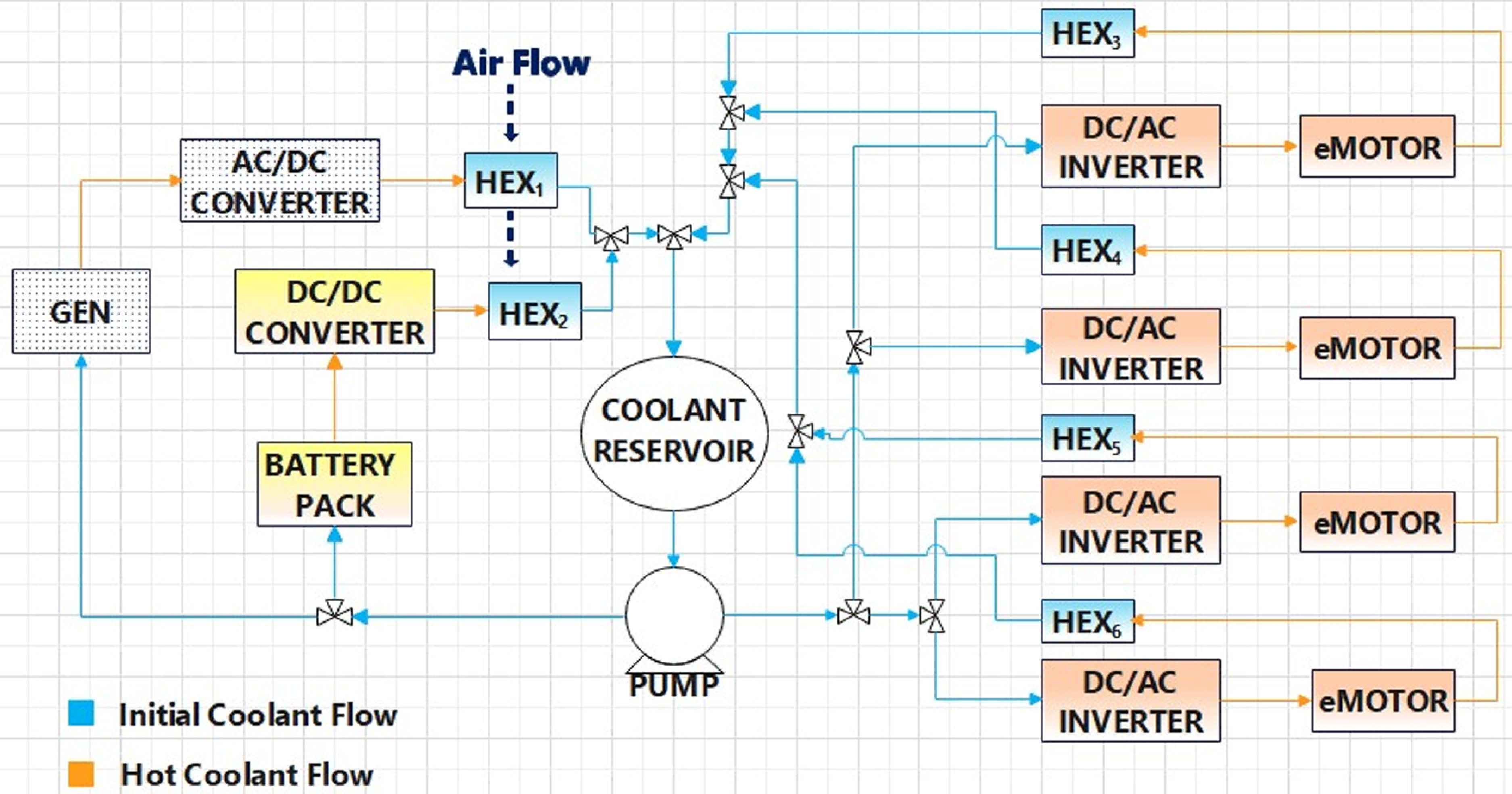
In the centralised architecture the total working liquid flow is cooled in a central heat exchanger via ram air, as illustrated on Fig. 2. However, in the decentralised arrangement each individual liquid flow is cooled on each loop with a separate heat exchanger, as presented on Fig. 3. Consequently six heat exchangers are employed. Essentially, these two systems represent the two extreme cases from a totally isolated to a fully redundant system. Thus, the latter is deemed safer, as it ensures that if any of the HEXs fail, the other compartments will remain sufficiently cooled. From the figures provided, it is concluded that apart from the differentiation in the number of HEXs, the architectures are similar. The working medium exits the tank and is pumped to six different routes, connected in parallel. In the first loop, the generator and AC/DC converter are cooled. On the second loop the batteries and their DC/DC converter are cooled. Furthermore, one loop is designed for every motor and DC/AC inverter pair.
Centralised TMS architecture.

Decentralised TMS architecture.
The heat exchangers considered in this report are of the compact crossflow HEX type with both fluids unmixed. Compact heat exchangers (CHEXs) are characterised by surface density β higher than 700m2/m3, and combine small weight as they feature the smaller possible volume, but also high efficiency [Reference Zohuri33, Reference London and Kays34]. For the heat exchanger dimensioning the effectiveness ( $\varepsilon$
) – number of transfer units (NTU), as it facilitates the calculation of the outlet temperatures of fluids. The NTU and the effectiveness for a crossflow heat exchanger with both fluids unmixed are defined as follows from Equations (1)–(3):
$\varepsilon$
) – number of transfer units (NTU), as it facilitates the calculation of the outlet temperatures of fluids. The NTU and the effectiveness for a crossflow heat exchanger with both fluids unmixed are defined as follows from Equations (1)–(3):
 \begin{align} \varepsilon = 1 - {\rm{exp}}\left( {{C_r}NT{U^{0.22}} \cdot \exp \left( { - {C_r}NT{U^{0.78}}} \right) - 1} \right)\;\end{align}
 \begin{align} \varepsilon = 1 - {e^{\left({C_r}NT{U^{0.22}}\left( {{e^{ - {C_r}NT{U^{0.78}}}} - 1} \right)\right)}}\end{align}
 \begin{align} NTU = \;\frac{{UA}}{{{C_{{\rm{min}}}}}}\end{align}
In order to design the heat exchanger, the values required are:
-
The working medium on both the hot and cold side.
-
Inlet and outlet temperatures for one working medium.
-
The thermal conductivity of each fluid.
-
Either the outlet or the inlet temperature of the other fluid.
-
An initial estimation for the total heat transfer coefficient U.
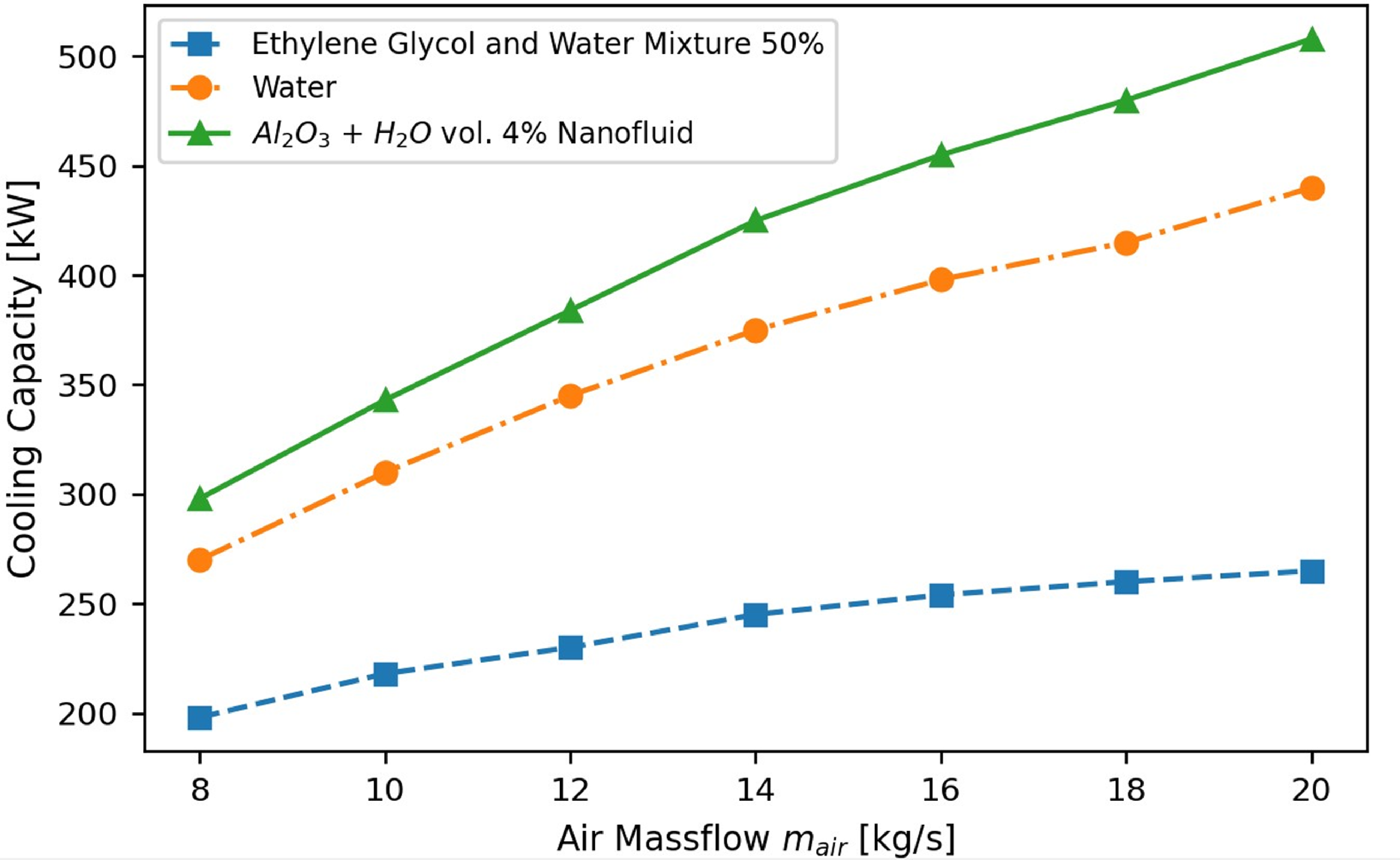
To assume the value of the total heat transfer coefficient, bibliographic research was conducted. In the work of Mortean et al. [Reference Hein and Mortean35]. Experimental testing on polymer CHEX was executed, to assess its performance, resulted in heat transfer coefficient with values 70–194, with varying Re number. Regarding CHEXs employing water and Al2O3 nanoparticles [Reference Krishna, Vasu and Kumar36], their U ranges from 150–200W/(m2K), depending on the mix ratio. This study further highlights this mixture’s high cooling capacity in comparison to water and EGW as presented on Fig. 4.
Furthermore, the performance analysis of plate fin CHEXs with conventional and improved rectangular, as well as twisted fins was studied [Reference Ning, Wang, Sun, Zheng, Zhang, Zhao, Liu and Yan37]. As the fins design is not explored during this research, regular fins, as non-improved fins were considered, to account for the most exacerbated CHEX efficiency. In this case, the U ranged from 168 to 224W/(m2K). In addition, in an application where an aluminum CHEX is employed for gas-turbine plant of power 3.7MW [Reference London and Kays34], with air and water, similar working mediums as the heat exchangers of the current research, the U was calculated 166W/(m2K). This value was selected to dimension this paper’s heat exchangers and all the values considered are presented on Table 2. It is also worth highlighting that other values were also examined but did not significantly alter the analysis results. Consequently, the coefficient’s impact on the results is considered minor.
Heat transfer coefficient values

Cooling capacity of various water-based coolants [Reference Hein and Mortean35].
2.2. Computational model development
To define the necessary functional parameters as well as the weight of the TMS, a computational model, consisting of two parts, is developed. The first part, the thermal model, calculates the minimum required HEX area. Afterwards, the weight model extracts the TMS compartments’ weights.
The computational model is compiled in Python, utilising the integrated development environment of Pycharm. Vital for its function is the use of numpy library as it allows to examine a range of values at once. Furthermore, with matplotlib library the results are plotted to draw conclusions. In an attempt to render the computational model in a more user-friendly manner, widgets are developed with tkinter library.
2.2.1. Thermal model
In order to dimension the HEXs, which is the objective of the thermal model, appropriate assumptions must be considered, regarding their performance. In this research, the whole heat transfer coefficient is 166W/m2K, and the efficiency of every HEX is assumed to be 0.95. Furthermore, the heat loads that the HEXs receive must be calculated. To achieve this, two heat loading scenarios are examined. Referring to the first, the conduction between the cooling fluid and each compartment. The second case considers the convection between the CP surface and its surrounding air, which is at 22.7°C and the heat transfer coefficient is estimated 30.68W/m2K [Reference Gkoutzamanis21]. The thermal loads are calculated from the formulas as follows.
 \begin{align} {Q_{{\rm{total}}}} = {Q_{{\rm{cond}}}} + {Q_{{\rm{conv}}}}\end{align}
 \begin{align} {Q_{{\rm{cond}}}} = k \cdot \left( {{T_{{\rm{lim}}}} - {T_{{\rm{air}}}}} \right)\end{align}
 \begin{align} {Q_{{\rm{conv}}}} = \left( {1 - n} \right) \cdot P\end{align}
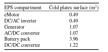
The cold plates surface for each propulsion compartment are presented on Table 3.
Cold plate surfaces
To execute the thermal computational model, the atmospheric conditions must be defined. The TMS’s design point is selected during the takeoff phase at sea level, where the highest EPS thermal loads are expected. In addition, as batteries feature elevated thermal sensitivity, three different atmosphere models are investigated. The baseline model implements an ECS, in order to regulate the ram air temperature at 7°C. The two alternative models examine hot (HDTO) as well as cold (CDTO) takeoff conditions, where the air’s temperature is 40°C and −10°C, respectively. As the atmospheric conditions are determined, the coolant mass flows as well as the temperatures for each point of the TMS can be computed. It is worth highlighting that propylene glycol thermophysical properties are obtained using the library pyfluids.
In reference to the centralised TMS (CTMS), utilising the energy equilibrium for the cold fluid, the air, and the hot, propylene glycol, the inlet and outlet temperatures for the cold and hot side can be calculated. Furthermore, the whole required coolant mass flow is defined. After the central HEX is sized, the mass flow of each loop and the temperatures of each compartment, are calculated from the energy equilibrium of ach compartment as presented below. While defining the operation temperatures in each loop, the inlet temperature of the coolant in the HEX is re-calculated. Subsequently a convergence criterion is introduced, so that the initial and final value of this temperature are equal.
On the decentralised TMS (DTMS) six HEXs must be sized, although it is considered that they are all cooled with the same air mass flow and feature the same performance characteristics. While on the centralised model, the whole mass flow is defined in the starting point of the cooling loop, the opposite occurs on the decentralised model. As both the inlet and outlet temperatures are defined for each HEX, the coolant mass flow of each cooling loop is computed. Consequently, the temperatures of each compartment are calculated and lastly the initial temperature of the coolant and the cumulative coolant mass flow. It is necessary to note that in this case, the convergence criterion, while expressed as in the centralised model, refers to each HEX separately. Therefore, three convergence criteria must be fulfilled. In addition, for both models, sensitivity analyses are conducted, for a range of inlet ram air mass flow and HEXs heat transfer surfaces. The goal is to minimise the heat transfer surface while ensuring safe operation of each compartment.
2.2.2. Weight model
With the completion of the thermal computational model, the heat transfer surface of each hex is defined, and necessary coolant mass flows. Subsequently the weight of each compartment can be calculated. Utilising the definition of the compressibility ratio, the HEX volume is derived from the following equation:
 \begin{align} {V_{HEX}} = \;\frac{{{A_{HEX}}}}{\beta }\end{align}
Consequently, the dry weight can be calculated from Equation (8), and the wet weight from Equation (9), considering that HEXs are constructed from aluminum. It is important to calculate both, as wet weight includes the coolant, with the assumption that 25% of porosity accounts for the liquid coolant channels. The above methodology for CHEX sizing is also presented in previous research of Gkoutzamanis et al. [Reference Gkoutzamanis21].
 \begin{align} {({W_{HEX}})_{dry}} = \;{V_{HEX}} \cdot {\rho _{HEX}}\; \cdot \left( {1 - \sigma } \right)\end{align}
 \begin{align} {({W_{HEX}})_{wet}} = \;{({W_{HEX}})_{dry}} + {V_{HEX}} \cdot \;\frac{1}{4}\; \cdot \sigma \cdot {\rho _{coolant}}\end{align}
Piping Weight
The piping system is comprised of the required routes to sufficiently cool the EPS compartments. One route is designed to cool the generator and its AC/DC converter, another for the battery pack and DC/DC converter and one for each motor and DC/AC inverter pair. The piping weight depends on the hydraulic diameter, which is considered 18 mm at all routes. In addition, the piping length is estimated from a preliminary CAD drawing. The wall thickness of the pipes is considered 1mm.
Pump power and weight
The pump’s purpose is to recover the liquid’s pressure loss during its circulation in all of the cooling loops. Pressure loss occurs both in the pipes and the EPS compartments. The piping pressure loss is calculated on each loop individually. The generator loop comprises 15% of piping, the battery pack loop 10% and each motor loop 17.5%, on both TMS architectures exists a joint route where the liquid coolant enters its reservoir, and is afterwards driven through the pump in the system. This route comprises 5% of the whole length. Therefore, the pipes pressure loss is derived from Equation (10).
 \begin{align} {({\rm{\Delta }}{{\rm{P}}_{{\rm{pipe}}}})_{{\rm{tot}}}} = {({\rm{\Delta }}{{\rm{P}}_{{\rm{pipe}}}})_{{\rm{bat}}}} + {({\rm{\Delta }}{{\rm{P}}_{{\rm{pipe}}}})_{{\rm{gen}}}} + {({\rm{\Delta }}{{\rm{P}}_{{\rm{pipe}}}})_{\rm{m}}} + {({\rm{\Delta }}{{\rm{P}}_{{\rm{pipe}}}})_{{\rm{joint}}}}\end{align}
Furthermore, for each route the pressure loss is dependent on the Darcy-Weisbach friction factor, and the liquid’s velocity. To calculate the friction factor empirical equations, like Colebrook-White are employed, according to Reynolds number. The EPS compartments pressure loss however, is derived from empirical data [Reference Gkoutzamanis21, Reference Zohuri33]. In both TMS designs the HEXs pressure loss is 2 bar, because of their narrow liquid channels. The other compartments feature a summed-up pressure loss of approximately 4 bar. Subsequently the compartments and the TMS pressure loss are defined from Equation (11).
 \begin{align} \left( {{\rm{\Delta }}{{\rm{P}}_{{\rm{TMS}}}}} \right) = {({\rm{\Delta }}{{\rm{P}}_{{\rm{pipe}}}})_{{\rm{tot}}}} + {({\rm{\Delta }}{{\rm{P}}_{{\rm{comp}}}})_{{\rm{tot}}}}\end{align}
The pump considered in this research is a rotodynamic, centrifugal kind. Its power can be derived from pressure loss through Equation (12), with the assumption that the impeller’s efficiency is 0.7 [Reference Moran38].
3.0. Results
3.1. Thermal model results
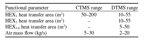
The central HEX of the TMS must be capable of dissipating a thermal load of approximately 250kW. To realise the minimum heat transfer HEX area required, sensitivity analyses are conducted for a range of ram air mass flows and HEX surface areas. The range of these parameters is presented in Table 4, and it is applied to all three atmospheric conditions: controlled by ECS, HDTO, CDTO. In addition, the effect of surrounding air convection is examined.
Regarding the DTMS, each HEX receives the thermal load of the compartments in the cooling loop it is placed. The lowest thermal load occurs on the motor loop at 30kW, while the battery and generator loops receive similar loads at 64 and 66kW, respectively. The range of the parameters examined are presented on Table 4, and as each HEX receives different heat loads, different heat transfer surface ranges are investigated.
While on the CTMS the strictest design constraint is imposed by the battery pack temperature that needs to be maintained at 40°C, on the DTMS more factors contribute. As each HEX is placed on a cooling loop, its design is affected by the compartment with the strictest temperature limit. On the generator and motor loops the compartments setting the limit temperature are the AC/DC converter and DC/AC inverter, respectively. The battery loop is restrained by the battery at 40°C.
3.2. Environmental control system conditions
3.2.1. Centralised thermal management system
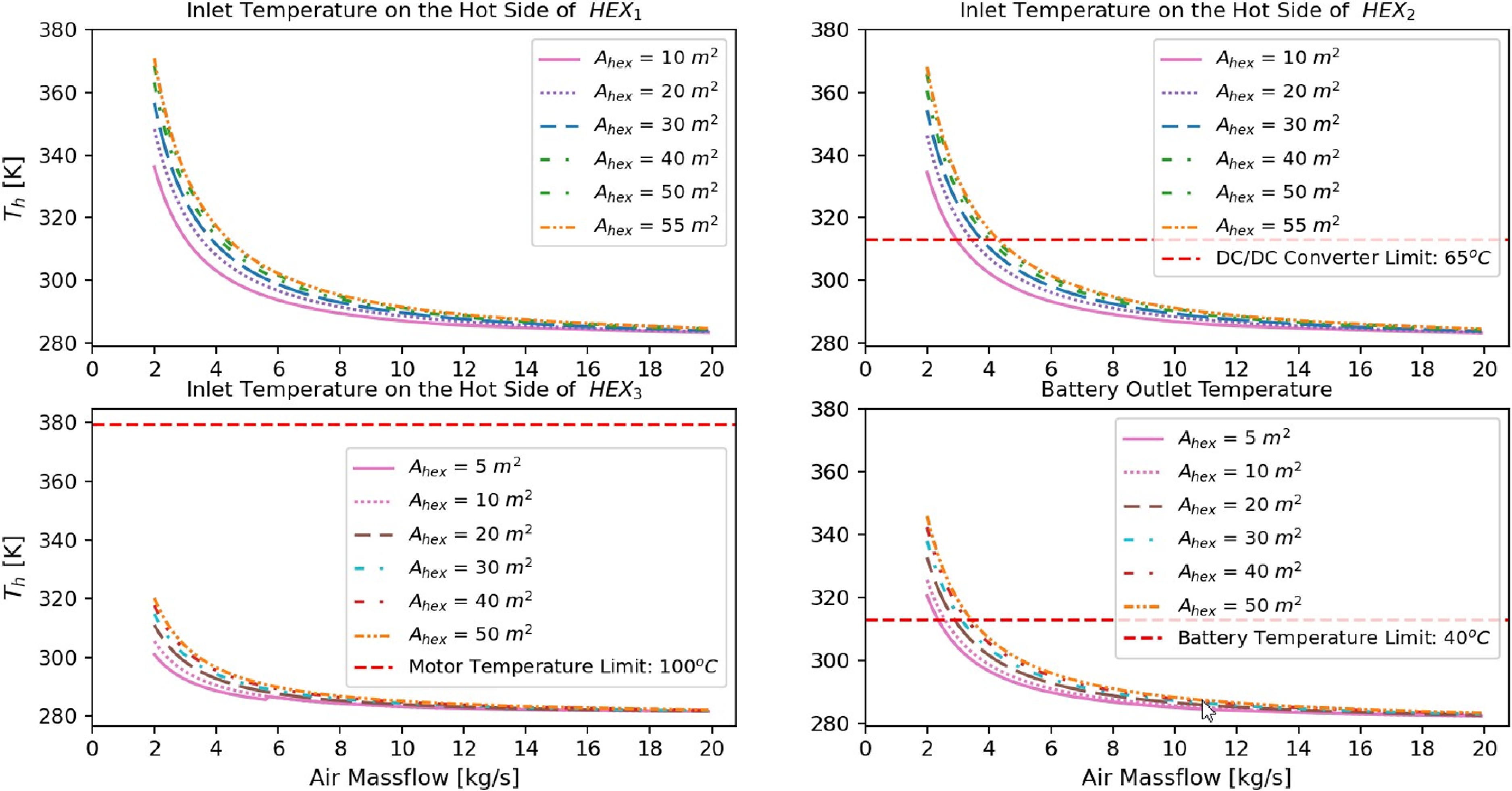
In Fig. 5, the inlet and outlet temperature of liquid coolant in HEX hot side are featured, including PGW50’s boiling point at 106,5°C, as temperatures must not surpass that. It is evident that higher air mass flow leads to lower temperatures. However higher heat transfer areas lead to increased temperatures.
Parameters examined on sensitivity analyses
Inlet and outlet temperature on hot side of heat exchangers, ECS conditions, CTMS.

Total required coolant mass flow, ECS conditions, CTMS.

Outlet coolant temperature on battery, ECS conditions, CTMS.

The liquid coolant mass flow, presented on Fig. 6, demonstrates opposite trends, as it increases with higher air mass flow, and decreases with higher heat transfer area. Consequently, there exists a tradeoff between heat transfer area and coolant mass flow. Furthermore, sensitivity analyses showcase that coolant mass flows higher than 2.8kg/s, exponentially increase pump weight.
The coolant temperature exiting the battery pack, essentially configures the HEX’s design space, as batteries must function below 40°C. This constraint is presented on Fig. 7, showcasing the outlet coolant temperature on batteries.
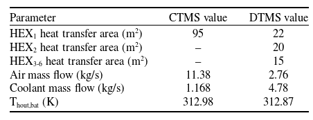
Considering the constraints analysed above, the selected values for the configuration, regarding ECS ram air conditions, feature 95m2 HEX area and 11.38kg/s air mass flow, which yield 1.68kg/s coolant mass flow. The results are presented on Table 5.
Decentralised thermal management system
As mentioned, each HEX of the decentralised design is affected by different constraints. Subsequently to determine each HEX’s heat transfer surface, sensitivity analyses were conducted, considering only its individual limitations in respect to the design. The results of the exploration regarding inlet temperatures of each HEX and the outlet battery temperature are presented in Fig. 8. It is evident that higher temperatures occurate the generator and battery loop, and the strictest sizing limitation is set by the outlet coolant temperature on the batteries.
TMS sensitivity analysis results for ECS conditions
Inlet temperatures on each HEX and outlet coolant temperature sensitivity analyses, DTMS.
Inlet temperature on hot side and required coolant mass flow of each heat exchanger, ECS conditions, DTMS.

In conclusion, the surface of the generator loop HEX is 22m2, the battery 20m2, and for each motor loop 15m2. As the HEXs heat transfer surfaces are selected, further sensitivity analysis, considering the whole TMS and convergence criteria set, are executed, to determine the required air and coolant mass flow. The temperature limits set for each cooling loop are presented on Fig. 9, where the outlet temperature of the coolant on each compartment is plotted. It is apparent from the required coolant mass flows on each loop that the motor and inverter loop need the highest mass flow. As there are four similar loops total this phenomenon exacerbates the value of the total coolant mass flow.
3.2.2. Hot day takeoff conditions
Centralised thermal management system
Assuming HDTO conditions, 40°C air is utilised to cool the HEX. Observing the temperature trends, a 5% increase can be realised. As mentioned above the battery pack’s temperature determines the viable design space for the HEX. On Fig. 10, presenting the coolant outlet temperature in battery pack, it is illuminated that a 40°C working temperature is unachievable even for extreme air mass flow values, for HDTO conditions. However, either attaching PCMs on the batteries or designing a separate cooling loop using a higher performance freezing liquid, could improve their temperature fields. Furthermore Lithium-sulphur (Li-S) batteries could further extend the operating temperature range, as this type of battery can operate at temperatures of up to 70°C [Reference Zhou, Li and Zhang39].
Outlet coolant temperature on battery, HDTO conditions, CTMS.

Subsequently, a higher limitation is examined, at 45°C, which requires air mass flow higher than 40kg/s. Such elevated air mass flow values, induce a ram-air drag, hence a limitation at 50°C is further investigated, which results in 29.18kg/s air mass flow. Hence this temperature limitation is selected, as presented on Table 6 and the necessary coolant mass flow is 5.63kg/s, which is 70% more than the mass flow at ECS conditions.
Decentralised thermal management system
At hot day takeoff conditions, the strictest requirement as mentioned above is outlet coolant temperature on battery as presented on Fig. 11.
TMS sensitivity analysis results for HDTO conditions

Inlet temperature on hot side and required coolant mass flow of each heat exchanger, HDTO conditions, DTMS.

Outlet coolant temperature on battery, CDTO conditions, CTMS.

As it occurred on the CTMS, the 40°C limit for safe battery operation is surpassed, as the required mass air mass flow must be further than 50kg/s. However, when the limit is adjusted to 50°C, the required air mass flow is 6.98kg/s, and the corresponding coolant mass flow is 15.75kg/s as illustrated on Table 6, which would greatly impact the pump mass.
3.2.3. Cold day takeoff conditions
Centralised thermal management system
At CDTO conditions, which occur at −10°C, operational temperatures decrease approximately by 5%, compared to ECS conditions. This can expand the viable design space for the HEX. Furthermore, except of the upper temperature limit for the battery pack at 40°C, a lower limit is introduced at −10°C, as their power is depleted. These constraints are presented at Fig. 12, where it is evident that all temperatures are higher than the lower limit.
TMS sensitivity analysis results for CDTO conditions
Inlet temperature on hot side and required coolant mass flow of each heat exchanger, CDTO conditions, DTMS.

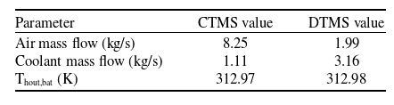
Accounting all design constraints and HEX transfer surface, the air mass flow selected is 8.25kg/s as presented on Table 7. In addition, the corresponding coolant mass flow is 1.11kg/s.
Decentralised thermal management system
At cold day take-off conditions, which occur at −10°C, accounting the battery pack limit temperature, as shown on Fig. 13, to sufficiently cool the TMS 1.99kg/s air mass flow is chosen.
Accordingly, the coolant mass flow is 3.16kg/s, which is 34% lower than at ECS. The results are summarised on Table 7.
3.2.4. Surrounding air free convection impact
Centralised thermal management system
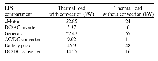
With the effect of free air convection, the thermal loads can be reduced as presented on Table 8 though not significantly. Batteries and generator loads showcase the highest reduction.
In particular, on lower air mass flows the convection is more favorable as temperatures can reduce by 1.7%. On higher air mass flow, a 0.4% reduction is observed. On Table 9, the required coolant mass flows are compared for every atmosphere condition examined, and the most important reduction is observed at hot day conditions by 4.3%.
Decentralised thermal management system
On the decentralised system also, the free stream air convection effect is investigated. The results are presented on Table 9, and a 0.2–0.4% reduction on the required coolant mass flow is realised. Furthermore, the convection induces a higher impact on the decentralised system as further reduction is realised.
Compartments heat loads with and without convection
Effect of convection on coolant mass flow

Compartments thermal limits, power outputs and thermal loads

CTMS weight breakdown.

DTMS weight breakdown.

3.3. Weight model results
3.3.1. TMS weight overall weight and breakdown
The weight calculations for both the decentralised and centralised TMS were conducted for the baseline model, which is designed at ECS conditions at 7°C. The weight breakdown and overall weight results are presented on Table 10 for both TMS architectures. Regarding the CTMS the total dry mass is 143.9kg, while the wet mass is 158.22kg, which induces a 9% increase. The DTMS dry mass is 219.4kg, while the wet mass is 6% more, at 233.48kg. The decentralised design’s wet mass is 32.2% higher than the centralised configuration. Therefore, the inclusion of the wet mass for both architectures is crucial.
On Figs. 14 and 15 the weight breakdown for both arrangements by percentage is presented. The HEX’s weight on the CTMS constitutes 80.5% of the whole weight while on the DTMS 58.6%. It is also worth noticing that the pump’s weight is 36.4% on the DTMS due to the high coolant mass flow necessary. To elaborate, the pump’s mass is 22.56kg on the centralised TMS, and 85kg on the decentralised TMS. The radically increased pump weight of the decentralised TMS stems from the high coolant mass flow, required to sufficiently cool the system. Furthermore, the required pumping power on the centralised configuration is 1,471.34W, while at the decentralised TMS is almost quadruple at 4,184.34W.
3.3.2. Pump weight variation
As illustrated above the pump weight especially on the decentralised TMS greatly affects the total mass, because of the high required coolant mass flow. Hence its design was investigated for the two alternative conditions. Sizing the pump of the centralised TMS during cold day takeoff conditions, would reduce its weight by 50%, at 13.22kg. However, at HDTO the weight is five times higher at 115.63kg. In reference to the decentralised TMS, at CDTO the pump’s weight Is reduced by 40% at 52.36kg, while at HDTO the weight in increased at 477.39kg, by 82%. It is evidently presented on Table 11 for the centralised and decentralised TMS, respectively, that an increase in coolant mass flow radically increases the pump weight.
3.4. TMS design sensitivity analysis
In conclusion, the weight of DTMS architecture is substantially higher than the CTMS. Furthermore, the thermal modelling results indicate significant differentiation between these two architectures. The above prove that the effect of the number of heat exchangers introduced in the design should be explored. To elaborate, a tradeoff occurs between the number of TMS HEXs and the required air mass flow to cool them. In addition, the required heat transfer area is reduced for higher coolant mass flow. On Fig. 16 the impact on the whole wet weight is presented and it appears to be linear, as it increases with increasing HEX’s number. On Fig. 17, the effect on required air mass flow is presented. At ECS and CDTO conditions, for the DTMS design the mass flow is almost equal while for the CMTS design a small variation is featured. On HDTO conditions, while the effect is still linear the gradient occurred is quite steep. The increase in HDTO conditions mass flow values highlight the importance of the ECS. The DTMS requires exponentially lower air. This effect renders the DTMS design appealing because higher air mass flow increases parasitic drag.
Pump sizing variation with atmosphere conditions

Weight variation with number of HEXs.

Ram air massflow variation with number of HEXs.

3.5. Error propagation analysis
3.5.1. Method
Since many design parameters are not determined during the conceptual design phase of an aircraft, an uncertainty (δx1, δx2,…,δxn) is considered to accompany design parameters (x1, x2..xn) deemed critical to the design. The formula and method used to examine uncertainty is presented on paper [Reference Gkoutzamanis21].
Uncertainties for design parameters

Uncertainty propagation for final parameters, CTMS configuration

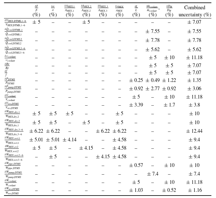
The variables investigated are the HEX surface, as it greatly impacts the TMS weight, the compact factor, the porosity and the HEX’s material density. Furthermore, the hydraulic diameter, the length of pipes and the coolant mass flow were explored. Initial relative uncertainties for the design variables must be determined, and are considered 5%. This value is selected as it an approximate practice occurring when working with at experimental data, and hence, the whole approach is viewed similarly to an experimental error propagation analysis. Variable uncertainties can be calculated afterwards, as presented on Table 12.
Uncertainty propagation for final parameters, DTMS configuration
3.5.2. Results
The results of the propagation of uncertainties of the TMS weights and its compartments are demonstrated on Tables 13 and 14, for the centralised and decentralised architectures, respectively. It is apparent that the first row showcases the design variables whereas the first column indicates the parameters where uncertainties occur. Moreover, on Table 15 the uncertainties for the total wet and dry weight for both designs are presented in order to compare them efficiently.
Referring to the centralised design, it is observed on Table 13, that the design variables related to the HEX equally affect the HEX dry weight and volume, while HEX’s wet weight is primarily influenced from the heat exchanger surface and compactness factor. Equally, as presented on Table 15, these variables affect equally the total dry and wet weight, though the material density features the highest influence inducing a 5.4% and 4.92% error, respectively. In addition, the pipe length majorly affects the coolant weight and volume, with 5% error. In contrast it slightly influences both dry and wet total weight. The same can be concluded for the hydraulic diameter as it induces the lowest error. Hence, it equally features a high effect at volume and weight of the coolant, the coolant velocity and piping weight at 10%. The last variable examined, the coolant mass flow, induce higher impact at heat transfer and pump weight while it equally affects friction factor, Reynolds number and coolant velocity.
As presented on Table 14 for the DTMS design, the dry and wet weight as well as the volume of all the HEXs, indicate the same dependencies to these variables. The distinguishing feature of the DTMS appears at the HEXs on the motor loops, as they feature higher errors than the others, at 6.22%. Furthermore, their surface has a higher impact on the total dry and wet weight than the other HEXs’, although the highest impact is introduced by the material density at 3.52%. The piping length and hydraulic diameter do not affect the total weight extensively. The piping length induces crucial error at coolant volume and weight at 5%. The hydraulic diameter instigates the same magnitude of error at volume and weight of the coolant, the coolant velocity and piping weight. Furthermore, the coolant mass flow, features a lower error at heat transfer of each HEX, though notable, compared to the centralised TMS, and introduces a 2.87% and 2.7% error at dry and wet weight sequentially.
Total weights uncertainty propagation for CTMS and DTMS architectures

4.0. Conclusions and future work
This research investigates the TMS design for a series hybrid aircraft propulsion architecture. To elaborate, two alternative configurations are examined: a centralised and a decentralised TMS, aiming to minimise their total weight, in order to induce lower impact on the aircraft’s total weight. For the research goals a computational tool was developed for the thermal and weight sizing of the TMS. The analysis conducted resulted in the following conclusions:
-
The decentralised configuration results in lower temperature fields for all components compared to the centralised configuration. Furthermore, the temperature curve features exponential trend with air mass flow. The equation of these two values could be shaped as: $T = a \cdot {e^{{m_{air}}}},\;\;a \in R.\;$
-
Battery pack’s assumed temperature limit at 40°C severely influence the TMS dimensioning. At HDTO conditions to produce a viable design for both architectures, their limit temperature must be increased to 50°C.
-
A tradeoff occurs between heat transfer area and the air and coolant mass flow. Increasing coolant mass flow reduces the required heat transfer surface area. The CTMS requires smaller coolant mass flow at 1.1682kg/s, while the DTMS requires 4.78kg/s. However, in order to cool the HEXs of the decentralised TMS less air mass flow is necessary, about 75%, for all atmospheric conditions examined. Furthermore, the necessary heat transfer area of the CTMS in 95m2, while for the DTMS is 102m2. Their deviation is 6.9%.
-
The pump’s weight at CDTO would be reduced by approximately 40%, while at HDTO conditions it would increase by 80%. This highlights the adverse effect of coolant mass flow in pump’s weight.
-
For both configurations, the HEXs’ weight is equally influenced by porosity, heat transfer area and compactness ratio, with 5% error. In addition, the error propagation analysis indicates that the total weight is majorly influenced by the HEX’s material density, as it induces an error of 4.92% and 3.52% for the centralised and decentralised TMS, respectively. Subsequently lighter materials than aluminum could further reduce the weight. The total weight is also influenced by the HEX surface.
-
The decentralised TMS weighs 233.48kg, which is 32.2% more than the centralised TMS (158.22kg) weight. Furthermore, the inclusion of the wet weight is illustrated as it is 6% and 9% increase in the decentralised and centralised TMS dry weight, respectively.

The discrepancy between the wet and dry weight, prove that the coolant mass impacts the weight. In this direction, a mixed TMS architecture, employing a liquid in combination with air or alternative solution (i.e. based on phase change solutions) attached to the batteries, could reduce the weight. The same benefit could be induced by constructing the HEXs from a lighter material than aluminum. Furthermore, including atmosphere temperatures higher than 40°C and lower than −10°C, would provide a more thorough TMS design exploration.


 Open access