


1. Introduction
Battery Electric Vehicles (BEVs) represent a key technological pathway for increasing the energy efficiency of transportation systems and reducing greenhouse gas emissions (Reference Simaitis, Lupton, Vagg, Butnar, Sacchi and AllenSimaitis et al., 2025; Reference Xia and LiXia & Li, 2022). The battery pack is central to BEV performance and economic viability, determining not only energy storage capacity but also reliability and safety under dynamic loads, which strongly influence overall vehicle performance and lifecycle cost. (Reference Haghbin, Rezaei Larijani, Zolghadri and Hedayati KiaHaghbin et al., 2025; Reference Rosewater and WilliamsRosewater & Williams, 2015).
As the battery pack is one of or the most expensive components of a BEV, its reliability is crucial for the overall usability, acceptance and residual valueof BEVs in the used-car market (Reference HooperHooper, 2017, Reference Hooper2017; Reference Hooper and MarcoHooper & Marco, 2016). Many of the 40% of faults caused by internal short circuits as well as of the 20% external short circuits of a battery pack are related or directly induced by vibrations (Reference Xiong, Sun, Yu and SunXiong et al., 2020). Vibration may cause, for example, loose connections on all integration levels from cell to pack, fatigue of load carrying structures, deflection with possible unwanted changes in contact stage, rattling, changes in boundary conditions or deterioration of seals, that then may foster corrosion.
It has been observed that final extreme tests for leakage at the end of several other environmental tests with the hot battery packs being immersed into ice-cold water have revealed loss of sealing properties from prior testing, (Reference Ahlbrecht, Schuhmann and AbertAhlbrecht et al., 2025).
The design of battery packs for Battery Electric Vehicles is a multi-level and multidisciplinary optimization challenge involving, but not limited to, Electrical Engineering, Mechanical Engineering, Thermodynamics and Data Science on various levels from cell to module, to pack and vehicle integration, (Reference Kutka, Müller, Fülöp, Dörnhöfer and BruneKutka et al., 2018; Reference Wang, Schutzeichel, Plaumann, Kletschkowski and PanesarJ. Wang et al., 2024).
Several opposing target-conflicts arise from the design requirements when designing BEVs, (Reference Beibl, Zumach, Wehrend, Züfle, Hein, Plaumann and KrauseBeibl et al., 2024):
-
• high power vs. high energy concerning the storage and output performance of the pack,
-
• isolation vs. conductivity regarding i.e., wanted and unwanted heat transfer as well as electrical power transfer or the isolation thereof,
-
• mechanical fixation vs. mechanical yield and deflection for changes in volume due to ageing (swelling), breathing from changes in the state of Charge (SOC) and thermal expansion as well as
-
• differential vs. integral design.
The latter represents a crucial design trade-off with advantages and disadvantages on both sides and forms the focus of the following contribution. Key design indicators can help in analysis and design.
When cells are clustered into modules, mechanical loads originating from road-induced excitations can be partially decoupled from the cells by the module structures. However, the additional structure increases the overall weight of the pack and reduces the volume available for “active” cell material, meaning the portion of space dedicated to actual energy storage within the cells. The integral vs. differential trade-off is also closely linked to conflicting design goals of reparability vs. efficiency. The lower weight and lower volume of an integral approach (with, for example, cells directly integrated into the overall pack structure or even glued directly into the car body) of same power and energy specifications offers a better efficiency by using less material as well as a better efficiency in operation because of less drag (due to less volume), less acceleration losses and less rolling resistance from lower weight compared to a differential approach. However, highly integral glued battery packs often have to be scrapped completely in cases of severe malfunctioning while a differential approach could still be repaired by replacing a single module, see also Figure 1. It should be noted that the rather ideal scenario of putting the cells directly in the vehicle body and chassis is still rather academic and not implemented fully in vehicles on the market.
Generic example of a highly integral BEV battery pack design vs. a more differential one

Figure 1 Long description
A diagram comparing two battery pack designs for Battery Electric Vehicles. The diagram illustrates the process flow from cell to car for both designs. On the left side, the differential approach is shown, starting with cells arranged in a module, then modules combined into a battery pack, and finally integrated into a floor section of the vehicle. The right side depicts the highly integral approach, where cells are directly integrated into the car structure. The diagram includes labels such as cell, module, battery pack, and floor section, with arrows indicating the flow from cells to the final vehicle integration. The differential approach is associated with benefits like step-wise development, less mechanical coupling, and better recycling, but also higher costs and less battery volume. The highly integral approach offers more battery volume and weight, less height, and lower costs, but comes with higher mechanical coupling, more stress on cells, and difficult repair and recycling.
Current research at HAW Hamburg focuses on the design of realistic testing methods and testing setups for the structural dynamics of large battery packs. For this purpose, numerous BEVs have been instrumented with accelerometers and measurement technology to obtain a comprehensive overview of road loads inducing mechanical stresses and deformations on the battery packs. To date, this dataset comprises hundreds of measurements conducted on nine different vehicles across a wide range of road surfaces. Some prior studies have shown large variations of the dynamic loads on the battery packs across different vehicle designs (Reference Heinzen, Plaumann and KaatzHeinzen et al., 2023; Reference HooperHooper, 2017; Reference Hooper and MarcoHooper & Marco, 2016; Reference PlaumannPlaumann, 2022). It is assumed that their structural dynamic behavior changes due to factors such as size and weight of the vehicle, the suspension system and its parametrization, the design of the interfaces between the battery pack and the vehicle, the stiffness of the vehicle body and chassis, road load factors like road roughness and driving speed, the level of integration within the battery pack.
The vehicles in the vibration measurements are out of their design phase. As OEMs typically only share very limited design information, any analysis conducted outside the OEM faces a significant lack of information from the prior design phase.
Nevertheless, the gathered data of various vehicles analyzed under different conditions needs to be clustered according to relevant influencing factors to obtain a more detailed understanding of how individual parameters affect the results, rather than relying on a general average across all measurements.
Moreover, clustering based on these influencing factors is valuable for planning future measurement campaigns, for instance by guiding the selection of vehicles to be tested. Given the vast diversity of BEV models, battery types, and sizes on the market, such measurements require a sophisticated design of experiments, as only a small fraction of the possible variations can practically be investigated.
A well-structured Design of Experiments (DoE) approach requires clearly defined key indicators that are independent of one another (Reference BaradBarad, 2014; Reference Jankovic, Chaudhary and GoiaJankovic et al., 2021). While partial dependencies - such as between weight and size - can be compensated by including additional design parameters, for instance energy storage capacity, the complete absence of quantitative indicators poses a major challenge for the entire process of DoE-based parameter studies and test method development. This issue is particularly evident in the context of the integral versus differential design aspect with respect to dynamic behavior.
Therefore, this contribution proposes a quantitative key indicator to assess the degree of integration for the battery pack and the pack within the vehicle under dynamic loads. Such an indicator will allow clustering of the measurement data according to the degree of battery pack integration across different vehicles, thereby facilitating the derivation of vibration load predictions from the large dataset for future designs with higher levels of structural integration.
2. State of the art
The interesting field of Design for Vibration Reduction is covered in literature with general approaches on how to include the challenging requirements of dynamic loads, its analysis and design for in earlier phases of product development instead of just testing them at the very end, often leading to costly design iterations, (Reference PaoPao, 1999; Reference Sturm, Bremer and MatthiesenSturm et al., 2019).
This contribution focuses on the dynamic behavior of BEV battery packs under vibration loads, with particular emphasis on their degree of structural integration.
2.1. Integral vs. differential design
In classical Engineering Design literature integral construction is defined as the combination of several parts into a single component (Reference Bender and GerickeBeate Bender & Kilian Gericke, 2021; Reference Pahl, Beitz, Feldhusen, Grote, Wallace and BlessingPahl et al., 2007).
While Reference Pahl, Beitz, Feldhusen, Grote, Wallace and BlessingPahl et al. (2007) primarily describe the distinction between integral and differential construction methods at a detailed design level, the present contribution extends this concept to the top-level design of an entire vehicle. In this broader context, the integral construction approach becomes closely related to the composite construction method, since any vehicle necessarily comprises various systems and subsystems that must be interconnected and structurally coupled.
As the current contribution needs to cluster a large number of measurements based on the level of integration in the tested vehicles without much information of the product architecture in the design phase this necessitates examining of the general interaction between battery pack parts and the vehicle. This helps developing testing methods particularly tuned to higher levels of integration assumed for future designs. This moves the focus to a better quantifiable connection aspect of a “composite construction” in Reference Pahl, Beitz, Feldhusen, Grote, Wallace and BlessingPahl et al. (2007), away from the very general “combination” aspect in integral construction. However, as described before, combination and connection of parts becomes very hard to distinguish the higher the level with more complicated connections and interactions of larger systems. Hence, the current contribution uses a definition that adds the definition from a composite construction of an “inseparable connection of several, differently made, parts into a single component” as in Reference Pahl, Beitz, Feldhusen, Grote, Wallace and BlessingPahl et al. (2007) to the integral design of a system:
The most recent and distinguished testing standard for battery packs of BEVs (ISO 19453-6 - Road vehicles - environmental conditions and testing for electrical and electronic equipment - Part 6; Traction battery packs and systems, 2020) uses a definition of three categories with the two extremes explained in the following.
Category 1 is characterized by a local mounting of the battery pack in the vehicle (point-load), where the stiffness of the vehicle body has no impact on the battery pack and no significant dynamic interaction of the battery pack with the vehicle chassis occurs for a typical DUT mass <20 kg.
Category 3 is characterized by a large area mounting in the vehicle with different loads at different points of the battery pack, where the stiffness of the vehicle body has a primary impact on the battery pack and the vehicle chassis is interacting with the dynamic stiffness of the battery. The battery pack can be even part of the carrying vehicle structure (structurally integrated).
According to ISO 19453-6 (2020), “the battery pack or (battery) system is strongly linked to the vehicle structure and fixture positions. As a result, all deformations that are applied to the vehicle structure can be transferred to the battery pack or system.”
Therefore, the assessment of the structural integration under dynamic loads is strongly connected to the interaction and coupling through the connection.
2.2. Metrics of integration in engineering design
Direct quantitative measures of the degree of integration have not been found in literature. However, some literature pursues similar goals in the field of modular product architectures (Reference Krause and GebhardtKrause & Gebhardt, 2018). Within the design of modular product architecture, aspects such as number of interfaces, number of components to fulfil certain technical functions are measured and to some degree adjusted in the design process. The conflict of highly integrated vs. standardized interfaces is analyzed in (Reference Inselmann, Wöller and KrauseInselmann et al., 2024). The quantitative metric of the number of interfaces involved is discussed regarding an ideal number of interfaces per module in (Reference MikkolaMikkola, 2001).
The possible larger number of interfaces in a modular product architecture is directly linked to a possible larger product in contrast to a highly integral product in (Reference Celona, Embry-Pelrine and Hölttä-OttoCelona et al., 2007). This suggests that a lower number of interfaces could be a metric and indicate a higher integration in product design.
Also, Reference Celona, Embry-Pelrine and Hölttä-OttoCelona et al. (2007) suggest that integral products have a high function-to-component ratio. Modular products in contrast have many components to a specific function that the product fulfils.
The number of realized functions is not a robust metric, since the function definition strongly depends on the level of abstraction or detail used by the person or group defining the function structure. Here the number of functions may vary depending on the choice of abstraction made by the people involved and not directly compare to a later design and manufactured product. Reference Celona, Embry-Pelrine and Hölttä-OttoCelona et al. (2007) provide guidance in a literature citation on how to measure the number of functions involved in a decomposition approach, but it is not directly applicable to the later use case of this contribution. As we later want to compare different battery packs of various manufacturers installed in vehicles on the market, it probably can be assumed that the number of functions per battery pack remains the same on higher architecture levels. However, the number of components and interfaces to achieve these functions vary.
Hence, quantifiable counts of components and interfaces can be used to quantify a level of integration.
Typical examples in Design Engineering literature on modularity, integration etc. often use smaller, easy-to-hold products with very distinct system boundary like cell phones, computers, music players.
This contribution focuses on a much larger product, the battery pack, that needs several levels of decomposition which may even change depending on what focus is used. Possible levels in the product architecture for analysis in the context of the contribution could be:
-
• the full Battery Electric Vehicle
-
• the battery pack
-
• possible mechanical modules within the pack
-
• cells, other components, such as the battery management system.
2.3. Battery pack design
Examples of Battery Pack volume designs and their integration into the vehicle can be found in (Reference Belingardi and ScattinaBelingardi & Scattina, 2023). The calculation of global vibration behavior of battery packs with Finite Element Analysis is described and analyzed in (Reference Wang, Shi and ZhangK. Wang et al., 2023) for its impact in global dynamic vehicle interaction. Measurement of road load excitation on BEV battery packs are described in (Reference Heinzen, Plaumann and KaatzHeinzen et al., 2023; Reference HooperHooper, 2017; Reference Hooper and MarcoHooper & Marco, 2016; Reference Kutka, Müller, Fülöp, Dörnhöfer and BruneKutka et al., 2018).
The following provides an example for different approaches how battery packs can be designed with the focus to integration.
Volkswagen uses a design with highly integrated pouch cells in easy-to-remove “modules” within the pack. The modules themselves are very hard to disassemble later on, while modules can be easily swapped. Obviously, exchangeability is only one way to measure modularity, but the example is based on this for now. Other vehicles from BYD use battery packs with very large cells called “blade cells” that do not need any more support structure of mechanical modules in the pack. Exchangeability is achieved by replacing single cells. Hence, the same basic functions on pack level are very differently mapped to different lower structure levels.
When comparing battery packs of similar energy content, such as those from the Volkswagen ID.Buzz (82kWh) with a BYD M6 (72kWh) and a Tesla Model 3 performance 2022-2023 (78kWh).
The number of cells would be very high for the Tesla design (4416 cylindrical cells), high for the Volkswagen pack design (288 pouch cells) and low for the BYD pack design because the latter one uses much larger cells (120-160 cells). With the same basic functions on pack level, this approach would indicate a possible higher integration for the BYD design.
However, the Volkswagen design integrated the much larger amount of cells very rigidly into very stiff mechanical “module” housings. When comparing the Volkswagen’s cell clusters in a stiff housing (12pcs) to BYD’s larger blade cells (120-160pcs), the Volkswagen design actually comprises fewer components for the same number of pack-level functions. The Tesla Model 3 battery pack contains many cells loosely grouped into four mechanical clusters, which would indicate a high level of integration. Given the loose packaging of the round cells with thin cooling metal sheets, the mechanical coupling is most likely less rigid than in the Volkswagen case.
Therefore, the mechanical coupling at subsystem levels must also be considered.
2.4. Analysis methods from dynamic signal analysis
The analysis of dynamic vibration or shock behavior of battery packs and BEVs can be found in several publications. In literature like (Reference DörnhöferDörnhöfer, 2019; Reference Kutka, Müller, Fülöp, Dörnhöfer and BruneKutka et al., 2018) a substantiation concept of battery packs in vehicles is developed using a multi-level approach. Contributions like (Reference HooperHooper, 2017; Reference Hooper and MarcoHooper & Marco, 2014) combine knowledge from several vehicle measurements of older BEV designs with rather differential design approaches. Existing test standards are currently deemed only useful in some selected cases as shown in (Reference Kjell and LangKjell & Lang, o.J.; Lang & Kjell, o.J.). (Reference Schmitt, Seifried, Sandmann, Zillmann and BruneSchmitt et al., 2018) analyze battery pack vibration in simulations. In (Reference Heinzen, Plaumann and KaatzHeinzen et al., 2023) it is demonstrated how possible realistic future test specifications could be derived from a preliminary test campaign of some BEV road load measurements.
Effects of interaction and coupling of the mechanical design may be assessed in vibration analysis by one or a combination of the following methods looking at the transfer functions:
-
• small differences in phase over a broad frequency range. This approach can be applied in reduced dynamic models of vehicle and battery pack, as shown by (Reference Schmitt, Seifried, Sandmann, Zillmann and BruneSchmitt et al., 2018; Reference Schramm, Hiller and BardiniSchramm et al., 2014)
-
• Comparing spatial deflections in vehicle and battery pack, especially for main modes in resonance (It can be hard to obtain enough data of measurements points in testing, but very common in FE Analysis), (ISO 19453-6 - Road vehicles - environmental conditions and testing for electrical and electronic equipment - Part 6; Traction battery packs and systems, 2020)
-
• Resonance frequencies shift when the vibration mass is changed
2.5. Simple spatial indicators for global battery pack deformation
In (Reference PlaumannPlaumann, 2022) a simple indicator for the measured global deflection in the first bending and torsion modes was developed. In addition, the local corner bending was associated with a simple indicator for analyzing the measurement of different vehicles on the same road conditions. This meant that simple statistical values like maximum or root mean square of one of the calculated time domain signals below could be used to assess how much the main bending modes or local corner bending from hitting an obstacle with one wheel would deflect the battery, see (Reference PlaumannPlaumann, 2022).
2.5.1. Detecting first and simple bending modes
With model simplifications as described in (Reference PlaumannPlaumann, 2022), it is possible to calculate a rigid body movement as shown in the following example from the measured vertical movements of the four corners. When looking for a simple indication of global bending in time domain, especially the difference between the mean of the vertical movements of all four corner points
 $${z_{mean}}$$
and the measured vertical movement of the point 5 in the middle
$${z_{mean}}$$
and the measured vertical movement of the point 5 in the middle
 $${z_{5,meas}}$$
yields the midpoint bending difference according to:
$${z_{5,meas}}$$
yields the midpoint bending difference according to:
 $${z_{mid,rel,\;bend}}\left( t \right) = {z_{5,meas}}\left( t \right) - {z_{mean}}\left( t \right)$$
as can be seen in Figure 2. The mean of the corner points normalizes any translational rigid body movements or rotations around the center.
$${z_{mid,rel,\;bend}}\left( t \right) = {z_{5,meas}}\left( t \right) - {z_{mean}}\left( t \right)$$
as can be seen in Figure 2. The mean of the corner points normalizes any translational rigid body movements or rotations around the center.
Global bending mode kinematic estimation

Other established methods in Transfer Path Analysis include mapping of modes from two different sets (i.e. loaded, unloaded) with the Modal Assurance Criterion MAC, see i.e. (Reference van der Seijs, de Klerk and Rixenvan der Seijs et al., 2016), respectively (Reference Harris and PiersolHarris & Piersol, 2002).
The linear dependence of vibration at two points can be analyzed using the coherence function, see i.e. (Reference AllemangAllemang, 2003; Reference Harris and PiersolHarris & Piersol, 2002). This would however necessitate a dense network of measurement points to be independent of local mode shapes. For the current analysis, the coherence function has been used in some analysis parts (see also (Reference PlaumannPlaumann, 2022)) but it is not helpful in deriving a post-production indicator for the level of integration between battery pack and vehicle because it is limited to very local effects only.
3. Methods
The following section proposes a method on how to assess structural integration within the pack and of the pack in the vehicle based on dynamic post-production measurements.
This helps with the underlying task of clustering vibration measurements of various battery packs in BEVs on the market into groups of higher and lower integration. This is needed to develop future vibration testing methods based on higher or lower battery pack integration levels.
Even though it is estimated that newer battery pack designs on the market foster a higher level of integration than older ones, the simple clustering based on the vehicle’s production date or market launch date is not meaningful. In the current phase the market shows many different design approaches with very different product architectures still emerging. Hence, it is even more important to cluster the current vibration measurements and compose possible testing methods based on different scenarios of future battery pack designs, be it more integral (for better fuel and cost efficiency) or more differential (for better replacement, reuse and later enhancement).
The proposed method must be able to assess at least a global level of integration of the battery pack in the car with some level of interaction.
Initially, methods of Transfer Path Analysis commonly used in structural dynamics and acoustics come to mind to assess the structural coupling of the battery pack to the rest of the vehicle. However, these measurements typically require a large number of measurement points (i.e., 50+ accelerometers or scanning laser vibrometer measurements) to map enough mode shapes with one another.
Here, a global assessment on general global bending behavior of the battery pack and the interaction with the rest of the vehicle in this would be enough for a clustering approach.
Therefore, an alternative approach was developed, making use of the fact that resonance frequencies of a bending mode shape will change, if mass is added to the vibration system.
In our case, the added mass is largely spread not directly on the battery pack but in the floor section of the passenger compartment. If the system of the battery pack is significantly coupled to the mass on the floor section of the car, then the measured resonance frequencies should drop due to the added mass. In a decoupled system, adding mass to the vehicle will not affect the resonance frequencies of the vibrating battery pack (Equation 1).
 $${f_{resonance}} = {\rm{\;}}\sqrt {k/m} $$
This change of resonance frequency for test runs with and without added mass can be easily measured with the existing setup as described in (Reference PlaumannPlaumann, 2022) and used for testing method development that takes possible future levels of integration into account (Reference Heinzen, Plaumann and KaatzHeinzen et al., 2023).
The principle is explained in the following example, where additional mass in the form of sandbags was applied to the floor section of a VW T5 vehicle. Here, no battery pack is considered, only the vibration of the rather large floor section of that vehicle is measured at the four corners between the wheels and the center point of the floor section.
Example of ideal coupling of added mass on the vibrating floor section

The results shown in Figure 3 indicate that two main bending modes (one in each horizontal direction) are significantly lowered (shifted to the left) by adding mass. Also, the increase of damping caused by the sand and gravel sacks can also be seen in the lowered amplitudes of the resonance with added mass. The rather low damping factor does not change the frequency itself significantly. Damping however, is an important treatment in reducing the vibration response and decreases the risk of failure of the design.
3.1. Mapping modes with and without additional load using MAC
If it is unclear which peaks in the frequency spectrum after adding mass correspond to the original peaks without added mass, then an analysis using the Modal Assurance Criterion (MAC) can be used. In this case, the mode shape vectors, ideally based on several measurement points spread over the mode shape, are compared using the normalized vector product (Reference AllemangAllemang, 2003). If resonance peaks shift by a few hertz (Hz), the mapping can be performed without comparing mode shape vectors, simply by using the nearest frequency in the unloaded plot. This was the case for the measurements under analysis here.
3.2. Proposed indicator
The drop of the resonance frequency depends on the ratio of the vibration mass in resonance and the added extra mass. Hence, we need the mass that is vibrating in a global bending mode shape like in Figure 2. This is described by the total mass of the battery pack as well as a certain percentage of that mass that is moving. The edges will not move, the center will move most when vibrating in that mode shape of the simple bending example. This percentage is called modal mass fraction or modal mass participation factor
p. It can be obtained from Finite Element Analysis or analytical estimations as shown in (Reference Aenlle, Juul and BrinckerAenlle et al., 2021; Reference IrvineIrvine, 2012a, Reference Irvine2012b). Assuming a simple model with the battery pack vibrating as shown in Figure 2 a modal mass participation factor of around
 $$p = 80\% $$
can be assumed with free rotation but fixed translation at the edge of the battery packs where it is connected to the car (Equation 2).
$$p = 80\% $$
can be assumed with free rotation but fixed translation at the edge of the battery packs where it is connected to the car (Equation 2).
 $${m_{vibrating}} = {m_{pack}}{\rm{\,*\,}}p$$
That means that a battery pack weighting 500kg in total would have around 400kg mass vibrating in the mode shape of Figure 2.
The BEV battery pack vibration dataset analyzed here includes numerous measurements on various road surfaces. From these resonance frequencies of the main bending mode shapes can be identified with good statistical averaging over a large amount of measurement data. In addition, the same measurements were repeated with extra mass added to the vehicle floor in the passenger compartment. For example, 200 kg of sacked sand is added to our example above. In an ideal one-degree-of-freedom-lumped-mass-vibration-system the extra mass will increase the vibration mass from 400 kg vibrating mass to 600 kg vibrating mass. The stiffness of the battery pack and the vehicle will remain unchanged so that the mass change of 600 kg instead of 400 kg lowers the resonance frequency by 20% if the added mass is coupled by 100% participation to the already vibrating mass without any further interface or connection influence. This coupling factor c of the added mass serves as a metric to quantify the interaction between a highly integrated battery pack and one that is more loosely connected (Equation 3).
 $${f_{change,{\rm{\;}}factor}} = \sqrt {{{k_{after}}/{k_{before}}\over({m_{vibrating}} + ({m_{added}}{\rm{\,*\,}}c)) \! \mathord / {m_{vibrating}}}} \;\;{with \; stiffnesses \; {k_{after}} = {k_{before}}}$$
 $${f_{after}} = {f_{before}}{\rm{\,*\,}}{f_{change,{\rm{\;}}factor}}$$
Or solved for c, depending on the frequency drop (
 ) observed in the measurements when adding 200kg mass to our 400kg vibrating mass (Equation 4):
 $$coupling{\rm{\;}}of{\rm{\;}}the{\rm{\;}}added{\rm{\;}}mass{\rm{\;}}c = \left( {{{{{m_{vibrating}}}}\over{{{f_{change,{\rm{\;}}factor}}^2}}} - {m_{vibrating}}} \right)/{m_{added}}$$
A 1% frequency shift $( \,{{f_{change,\;factor}} = 99\% })$
at this mass configuration corresponds to: 8 kg of the 200 kg extra mass is coupled to the vibration system, which results in 4% mass of the mass being coupled ideally. A 5% frequency shift
$( \,{{f_{change,\;factor}} = 99\% })$
at this mass configuration corresponds to: 8 kg of the 200 kg extra mass is coupled to the vibration system, which results in 4% mass of the mass being coupled ideally. A 5% frequency shift $( {{f_{change,\;factor}} = 95\% })$
indicates that 41 kg of the 200 kg extra mass is coupled ideally, resulting in a coupling factor of 20%.
$( {{f_{change,\;factor}} = 95\% })$
indicates that 41 kg of the 200 kg extra mass is coupled ideally, resulting in a coupling factor of 20%.
4. Results
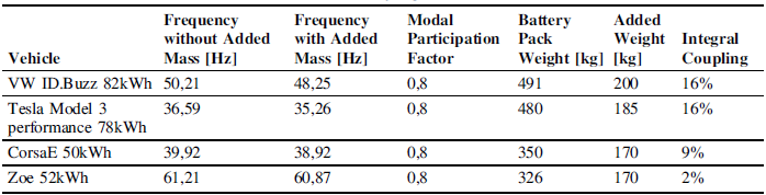
The proposed indicator has been used to analyze some of the existing measurement sets for some vehicles. The first global bending mode has been estimated from the measurements and the averaged resonance frequency of this bending mode has been derived for both loaded and unloaded conditions. The loaded condition included the additional weight distributed across the vehicle floor, while the unloaded condition comprised only the weight of the driver and the measurement equipment.
Observed frequency changes of battery pack bending resonance when adding mass and derived coupling factor

Here, the larger and heavier battery pack and vehicle designs in the measurements show a slightly higher coupling factor. This contradicts initial expectations where larger vibration areas should have more mass vibrating freely than smaller packs with a closer distance of cells to the next mounting at the outer frame. On the other hand, the heavier and larger designs have several stiff fixation screws connecting the rather rigid mechanical battery modules to floor section in general.
Smaller battery packs, such as that of the Corsa E, rely mainly on fixation of the outer frame and may exhibit weaker coupling of the vibrating center of the battery pack.
Limitations
Obviously, integral design is more than just rigid connection, direct coupling and less interfaces. Most importantly, the product architecture with its decomposition into subsystems matters. One product may have a high level of integration on one architecture subsystem level but a low level of integration on another. The proposed indicator for a post-production analysis can therefore only be a coarse indicator averaging the overall behavior to the level of the analysis where no further details from the design phase are available.
5. Conclusion
The contribution proposes a method to cluster existing measurements of vibrations of BEV battery pack under road load excitation based on the coupling between battery pack and vehicle. This key design indicator is needed to estimate which of the measured cars are representative for what level of integration of the battery pack in the vehicle in order to generalize vibration behavior of battery packs in BEVs also for future designs which could use much more integral designs. Based on the results, vehicles such as the Tesla Model 3 Performance and the Volkswagen ID. Buzz, both equipped with their largest battery variants, appear to be representative of more highly integrated designs.
Therefore, the vibration characteristics of these vehicles can be considered to represent a higher integration level (which is also assumed for future vehicles) when defining vibration test levels in a broad statistical analysis. A typical option would be to have a higher weighting of these measurements in the statistical analysis or extrapolate trends on how different levels of integration would change vibration characteristics. The design of the final test method and a test specification with consideration of the level of integration is still an ongoing research topic. Future research will further expand the number of vehicles measured from currently nine even more. Also, a verification of the proposed indicator with information of the underlying product architecture, i.e., from a tear down analysis, will be targeted where that information is available.
Acknowledgement
The authors would thank the German Federal Ministry for Economic Affairs and Energy for the funding of the research project GRISU.



 Open access

