


1. Introduction
Foilless diode is widely used in high-power microwave generation [Reference Korovin, Rostov and Polevin1–Reference Carmel and Nation3], free-electron lasers [Reference Grossman, Marshall and Schlesinger4], and magnetically confined plasma heating [Reference Robertson and Fisher5]. Since Friedman and Ury developed an electron beam injection gun guided by external magnetic field in 1970 [Reference Friedman6, Reference Friedman and Ury7], extensive work has been done in the past 50 years in producing high-power relativistic annular electron beams [Reference Eltchaninov, Kovalchuk, Kurkan and Zherlitsyn8–Reference Wu, Huo, Sun, Chen and Liu12]. The electron beam produced by foilless diode is usually highly annular, and its space-charge limited current is much higher than that of solid beam, which means that higher current can be transported in vacuum [Reference Jones and Thode13, Reference Sun, Wu and Huo14]. Therefore, foilless diodes are well capable of high-power density, long pulsed, and repetitive operated applications, such as high-power microwave devices and microsecond pulse electron accelerators [Reference Liu, Yang, Sun and Zhang9].
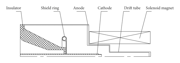
The axial foilless diodes immersed in solenoid magnetic field are widely used in O-type high-power microwave devices [Reference Lau, Friedman, Krall and Serlin15–Reference Zhang, Jin and Yang18], as shown in Figure 1. The advantage of the structure is that the diode cathode is completely immersed in the uniform strong magnetic field of solenoid coil, which is conducive to the generation of high-quality annular electron beams. In the development of high-power microwave system, low power consumption and miniaturization are important conditions for the practical application [Reference Gaudet, Barker and Buchenauer19–Reference Jin, Zhang and Yang21]. However, the traditional foilless diode structure has the following disadvantages [Reference Xiao, Sun and Huo17, Reference Cao, Sun and Wu22–Reference Xiao, Zhang and Zhang24]: (a) in order to avoid excessive radial electric field, the radius of drift tube is usually large, which makes the size of inner wall of solenoid coil much larger than that of microwave device and drift tube, resulting in waste of excitation space; (b) if the diode is to be further miniaturized, it is necessary to reduce the distance between diode cathode and drift tube wall, and this change will lead to the enhancement of the electric field intensity on the cathode emitter, which is very easy to cause the radial emission of electrons on the cathode, thus causing the loss of electron energy. Some electrons even form reverse motion, bombarding the insulator and damaging the insulation system [Reference Cao, Sun and Wu22]; (c) moreover, the volume, weight, and energy consumption of solenoid coil and auxiliary power equipment are large, which is not conducive to the application on mobile platforms.
Schematic of a typical foilless diode with solenoid coil magnetic field system.
In order to reduce the size of the foilless diode, improve the transmission efficiency of electron beam, and reduce the weight and power consumption of the guiding magnetic field system, a new type of axial foilless diode with a composite guiding magnetic field system is developed in this paper. The simulated and experimental results are believed to lay the foundation for the miniaturization, lightweight, and low power consumption of high-power microwave system.
2. Design of an Axial Foilless Diode with Composite Magnetic Field System
2.1. Structure Design of the Foilless Diode
The structure of miniaturized foilless diode guided by a composite magnetic field system is shown in Figure 2. The composite magnetic field system is mainly composed of solenoid coil, permanent magnet, and soft magnet. The inner radius, outer radius, and axial length of the solenoid coil are 47.5 mm, 168.5 mm, and 400 mm, respectively, and the ampere-turns of the solenoid coil is 315,000. The soft magnet material is steel Q235. The permanent magnet is made of sintered Nd-Fe-B with magnet brand N48, and its outer surface is coated with stainless steel 304, which has the functions of fixing and protecting permanent magnet, blocking electron bombardment, and preventing corrosion of permanent magnet material.
Schematic of a compact foilless diode with a composite magnetic system (solenoid coil, permanent magnet, and soft magnet).
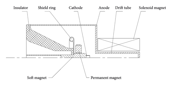
The main features of the new axial foilless diode are as follows: the emission cathode is set outside the central hole of solenoid coil so that the size of the inner wall of solenoid coil and the excitation space can be reduced, and also the volume and weight of the solenoid coil and its auxiliary equipment can be reduced. Furthermore, the electric field strength on the cathode can also be effectively reduced, which greatly reduces the probability of radial electron emission, avoids unnecessary energy loss, and reduces the risk of insulation failure caused by return electrons [Reference Cao, Sun and Wu22]. In order to increase the magnetic field intensity in the cathode emission region, a permanent magnet is set outside the cathode rod. In addition, the cathode rod is made of soft magnetic material, which can further improve the magnetic field strength in the cathode emission region by using its function of gathering magnetic field, so as to optimize the magnetic field distribution between the cathode and the anode (A-K gap).
2.2. Design of the Composite Magnetic Field System
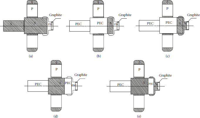
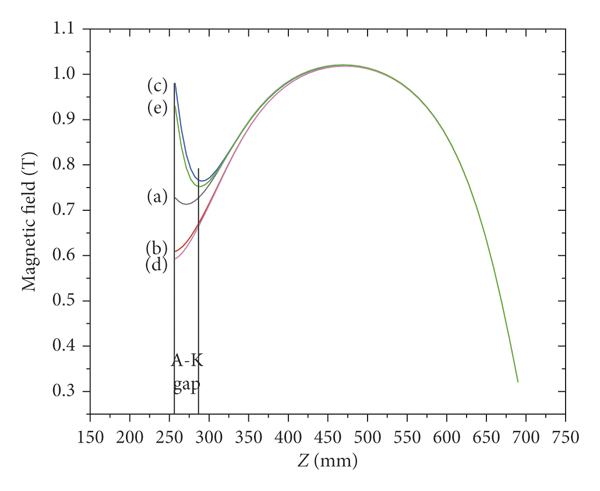
In order to study the influence of soft magnet structure layout on magnetic field intensity distribution, five kinds of soft magnet structure layout are designed, as shown in Figure 3. The distributions of axial magnetic field intensity are presented in Figure 4. The simulated results show that the distribution of magnetic field intensity in cathode emission region is greatly affected by different soft magnetic structures. The closer the soft magnet is to the cathode emitter is, the higher the magnetic field intensity is, as shown in Figure 4. However, if the soft magnet is too close to the cathode emitter (as shown in Figures 3(c) and 3(e)), the magnetic field intensity changes dramatically in the A-K region: the magnetic field near the cathode emitter is very strong but decreases rapidly in the direction of electron beam transmission and then increases slowly, as shown in curves (c) and (e) in Figure 4. Such magnetic field configurations will cause the electron beam to vibrate violently, which is not conducive to the high-efficiency interaction between the electron beam and the microwave cavity. In comparison, the structure model shown in Figure 3(a) is the optimal arrangement of soft magnet, and its magnetic field configuration shown in curve (a) in Figure 4 can not only obtain high magnetic field intensity in the A-K region but also ensure the stable transmission of electron beam.
Five kinds of soft magnet structure layout. P for permanent magnet; S for soft magnet.
The distribution of composite magnetic field intensity along the axial direction under different arrangements of soft magnetic, as shown in Figure 3. The curves (a), (b), (c), (d), and (e) in this figure correspond to the structure models (a), (b), (c), (d), and (e) in Figure 3, respectively. The magnetic field strength of solenoid coil is 1 T, and that of permanent magnet is 1.4 T.
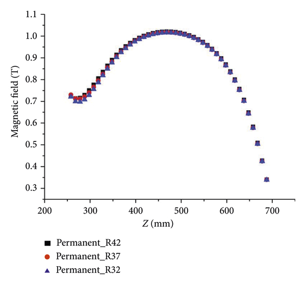
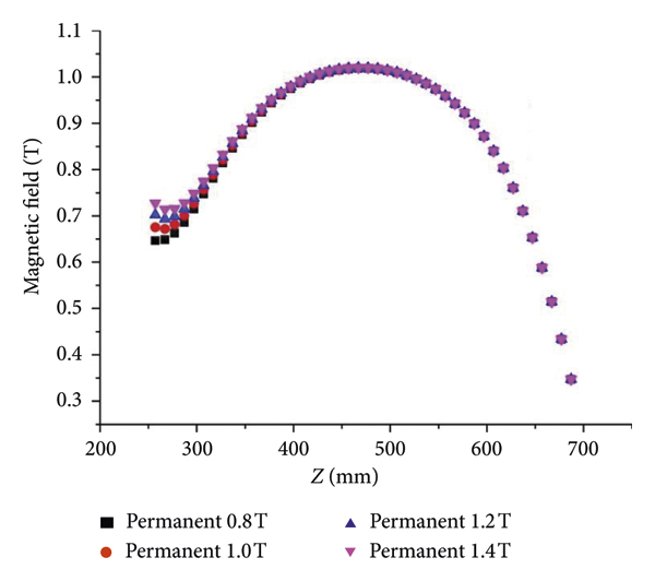
Based on the composite magnetic field structure in Figure 3(a), the influence of different radial sizes of permanent magnet on the axial magnetic field intensity distribution is studied with a magnetic field strength of solenoid coil 1 T and that of permanent magnet 1.4 T, as shown in Figure 5. It can be seen that the radial size of permanent magnet has little effect on the axial magnetic field intensity distribution. And also, the influence of the permanent magnet magnetic field strength on the axial magnetic field intensity distribution is presented, as shown in Figure 6, and the magnetic field strength of solenoid coil is set as 1 T. It can be seen that, with the increase in magnetic field strength of permanent magnet, the magnetic field strength in the A-K region increases stably, which benefits electron beam transmission. The influence of the magnetic field strength of solenoid coil on the axial magnetic field intensity distribution is presented, as shown in Figure 7, and the magnetic field strength of the permanent magnet is set as 1.4 T. It can be seen that the magnetic field strength in the A-K region and the drift tube increases significantly, and the growth rate of magnetic field intensity in drift tube region is faster than that in A-K region. When the magnetic field strength of solenoid coil is too large, the magnetic field intensity in the drift tube area is far greater than that in the A-K region, and the uniformity of magnetic field intensity along electron beam transmission path becomes worse, which is not conducive to the full utilization of solenoid coil energy storage. In order to reduce the energy consumption and the weight of the solenoid coil, the magnetic field strength of solenoid coil is set in the range of 0.5 T to 1.0 T, which has a better efficiency cost ratio.
The distribution of the composite magnetic field intensity along the axial direction with different radial sizes of the permanent magnet based on the model shown in Figure 3(a). The radii of the permanent magnet are 32 mm, 37 mm, and 42 mm, respectively; the magnetic field strength of solenoid coil is 1 T; and that of permanent magnet is 1.4 T.
The distribution of the composite magnetic field intensity along the axial direction with different permanent magnet magnetic fields based on the model shown in Figure 3(a), and the magnetic field strength of solenoid coil is 1 T.
The distribution of the composite magnetic field intensity along the axial direction with different magnetic field strengths of solenoid coil based on the model shown in Figure 3(a), and the magnetic field strength of permanent magnet is 1.4 T.
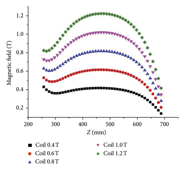
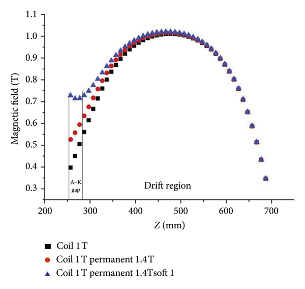
Figure 8 presents the axial distribution of magnetic field intensity in the diode with three types of magnetic field system. The results show that the distribution of magnetic field strength and the uniformity in the A-K region are improved significantly when the soft magnet is applied. Magnetic field strength of solenoid coil plays a decisive role in guiding magnetic field strength along the electron beam transmission path, while permanent magnet and soft magnetic field play an important complementary role in magnetic field strength in the A-K region.
The axial distribution of magnetic field in the diode. (a) Only 1 T solenoid coil. (b) 1 T solenoid coil and 1.4 T permanent magnet. (c) Composite magnetic field system with 1 T solenoid coil, 1.4 T permanent magnet, and soft magnet.
2.3. Calculation of Weight and Power Consumption
Table 1 shows the parameter comparison data of single solenoid coil system and composite magnetic field system. The weight of permanent magnet, soft magnet, and solenoid coil are 14.1 kg, 7.5 kg, and 216 kg, respectively. The power consumption of solenoid coil in the composite magnetic field system is about 16 kW. When the traditional solenoid coil magnetic field system (as shown in Figure 1) is used to guide the axial electron beam with the same axial magnetic field intensity, the weight of the corresponding solenoid coil is about 420 kg, and the power consumption is about 30 kW. Compared with the traditional solenoid coil magnetic system, the weight and power consumption of the composite guiding magnetic field system proposed in this paper can be reduced by about 40%.

3. Analysis of Electron Transmission Efficiency
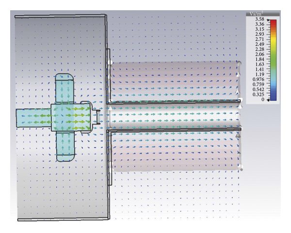
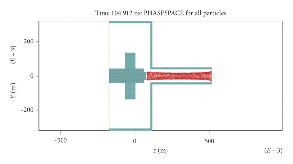
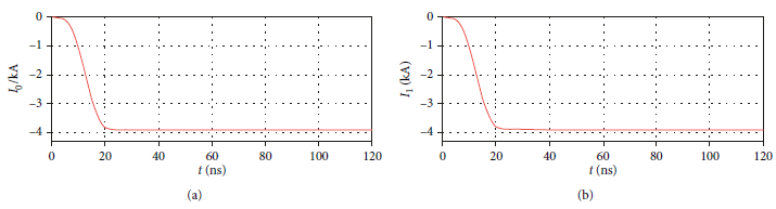
Using the composite guiding magnetic field system with permanent magnetic field strength 1.4 T and that of solenoid coil in the range of 0.5 T–1 T, PIC simulation is carried out to obtain the axial electron beam transmission trace. Figure 9 presents the spatial magnetic field intensity distribution. It can be seen that the magnetic field intensity is evenly distributed along the transmission path of the electron beam. The electrons emitted by the cathode can be transmitted 100% through the drift tube, no electrons are emitted to the drift tube wall, and no return electrons are generated, as shown in Figure 10. The electron beam current output waveforms at the transmitter and receiver are presented in Figure 11. It can be seen that the current waveform at the emitter is the same as that at the receiver, and the current amplitude is the same, which proves that the electrons emitted by the annular cathode are transmitted to the receiver 100%.
The spatial magnetic field intensity distribution.
The electrons trace guided by composite magnetic field.
Waveforms of emitted current and received current: (a) the current waveform at the transmitter; (b) the current waveform at the receiver.
4. Experimental Results
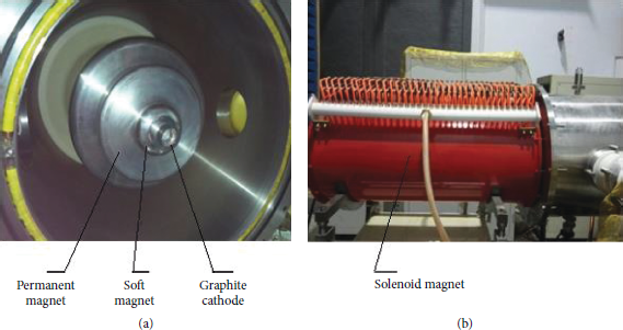
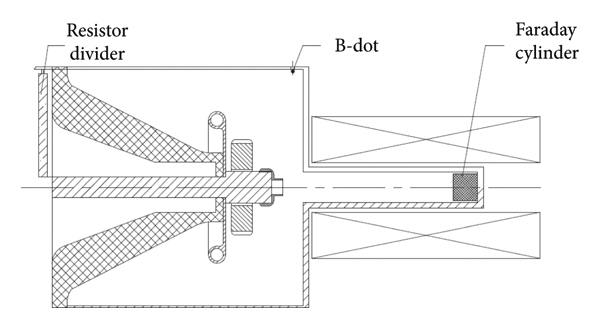
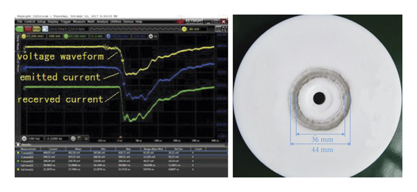
The developed foilless diode with composite magnetic field system is shown in Figure 12. Based on this foilless diode, experimental research was carried out on a compact PFN-Marx pulse power generator [Reference Song, Li, Zhang, Gong, Gan and Jin10]. The diode voltage is measured by resistor divider, the total current of diode is measured by B-dot, the current at the end of drift tube is measured by Faraday cylinder, and the arrangement of measurement devices is shown in Figure 13. The experimental results show that, under the condition of solenoid coil magnetic field strength 0.98 T and permanent magnetic field strength 1.4 T, transmission efficiency of the annular electron beam with voltage 636 kV (728 kV) and current 3.3 kA (5.7 kA) is 100%, and the diode impedance is 194 (128) Ω. Under the condition of solenoid coil magnetic field strength 0.5 T and permanent magnetic field strength 1.4 T, the transmission efficiency of the annular electron beam with voltage 590 kV and current 2.6 kA also achieves 100%, and the diode impedance is 220 Ω. The output voltage and current waveforms of single pulse are shown in Figure 14. The beam image of single shot is also presented in Figure 14, the outer and inner diameters of the electron beam are 44 mm and 36 mm, and the emission is uniform.
Developed foilless diode with composite magnetic field system.
Configuration of voltage and current measurement devices.
Output waveforms of single shot and the beam spot.
5. Conclusion
In this paper, a compact relativistic electron beam diode guided by composite magnetic field is proposed. By using the nonimmersion cathode structure, the inner diameter of the anode tube is reduced, and the radial emission of electrons on the cathode surface is suppressed. Moreover, the high-efficiency transmission of electron beam is realized. The simulation and experimental results show that when the magnetic field strength of permanent magnet is 1.4 T and that of solenoid coil is in the range of 0.5 T∼1 T, the transmission efficiency of electron beam can reach 100%, and the impedance of diode can be adjusted in the range of 100 Ω∼240 Ω.
The composite magnetic field system developed in this paper effectively utilizes the magnetic field at the end of the solenoid coil, giving full play to the advantages of permanent magnet and soft magnet. Under the condition of satisfying the magnetic field intensity required by electron beam transmission, the axial and radial dimensions of solenoid coil are shortened, and the miniaturization and lightweight of magnetic field system are realized. The volume, weight, and power consumption of the composite magnetic field system can be reduced by about 40% compared with the original system.
Data Availability
The data used to support the findings of this study are available upon request.
Conflicts of Interest
The authors declare that they have no conflicts of interest.


 Open access