
INTRODUCTION
The first ventilation system in the House of Commons, completed as part of Charles Barry’s architectural scheme for the new Palace of Westminster in 1852, was developed by the Scottish physician David Boswell Reid (1805–63). Reid, referred to as the ‘ventilator’, was originally employed by the Department of Woods and Forests to develop a ventilation scheme for the entire palace; however, his early scheme was discarded after six years. In 1846, responsibility for ventilation of the building (though not the House of Commons) was transferred to Barry. Ventilation in the House of Commons was the only part of Reid’s original scheme that was realised, and was operational for only two years until it was decommissioned and replaced with a new system. The last remaining physical remnants of Reid’s original system were ultimately destroyed by the Luftwaffe in 1941. The current debating chamber, designed by the architect Giles Gilbert Scott at the end of World War II, is equipped with a modern air-conditioning and ventilation system by the mechanical engineer Oscar Faber.Footnote 1 Except for fragments of the original air supply channels inside the roof and basement, none of the original physical features has survived.Footnote 2
While it could be argued that Reid’s original system was an unsuccessful and short-lived experiment, this paper intends to show that he accomplished a highly complex and sophisticated system that was the outcome of extensive enquiries into technical, environmental and human aspects of ventilation and climate control. These included experiments with full-scale temporary structures, which began in the spring of 1836 with the construction of a physical model of the debating chamber in Edinburgh and were continued in Westminster, this time under real-life conditions, inside the temporary House of Commons and the temporary House of Lords. These Houses had been erected by the architect Robert Smirke in 1834, a few months after a fire had destroyed the original medieval palace, to provide parliament with provisional accommodation. Reid’s experimental enquiries were followed by the development of his first, but unrealised, scheme, in which the House of Commons formed an integral part of a central ventilation system servicing the entire Palace of Westminster. This earlier scheme represents an important link between his experimental enquiries and his final scheme for the permanent House of Commons. This link has received little recognition in the existing literature.Footnote 3 Although the palace is widely recognised as being an important building within the history of environmental technology,Footnote 4 neither Reid’s early proposal nor the final design for the permanent Houses of Commons has been studied in any depth before.Footnote 5 The work of architectural historiansFootnote 6 and historians of environmental designFootnote 7 has focused primarily on the overarching concept behind Reid’s early masterplan, while the sophisticated arrangements inside the House of Commons has remained largely uninvestigated.
This paper provides a detailed reconstruction of the lost system inside the House of Commons, and retraces its evolution using original archival material, such as letters, sketches, architectural plans, technical reports and parliamentary papers.Footnote 8 In addition, historical measurements, eyewitness accounts and reports of scientific experiments are used to reconstruct the climatic and atmospheric conditions within the debating chamber and how scientists, engineers and MPs were involved in the empirical evaluation of the system. A new perspective is offered on the study of historic buildings by illuminating how architectural technology in the mid-nineteenth century was evaluated based on environmental criteria. Although environmental factors, such as climate or air purity, are more transient dimensions of architecture, they were part of the physical reality that affected the MPs’ experience of the chamber from the perspective of thermal comfort and air quality. As the objective behind the development of the sophisticated system was to enhance the MPs’ personal experience, the state of the internal environment became the primary criteria in the evaluation of its performance, and a deciding factor in the decision to decommission Reid’s system after two years.
REID’S BACKGROUND
Reid was thirty years old when he was approached to give technical advice on the ventilation of the Houses of Parliament. This was the first time that he had been involved in a large architectural project. Reid was a teacher and scientist with no background in engineering or architecture. In fact, he had trained as a medical doctor at the University of Edinburgh, and for fifteen years had pursued a career as a lecturer and researcher within the field of chemistry.
While working as a university lecturer under Thomas Charles Hope, professor of chemistry at the College of Surgeons, Reid began to develop new approaches to the teaching of chemistry, focusing on experimental research as a practical skill, its application within industry and its use as a design tool, including the use of scientific methods to address fundamental problems of ventilation. In several textbooks, which Reid had written for chemistry students, he not only illustrated how to conduct certain experiments, but also illustrated how these could be used to examine different aspects of ventilation, such as the chemical assessment of indoor air quality.Footnote 9 Unsuccessful in establishing a separate chair for ‘practical chemistry’ at the College of Surgeons, Reid left and, in 1833, established a private chemistry laboratory in Edinburgh with new purpose-built facilities for teaching and experimental research.
The laboratory facilities were based on Reid’s own plans and incorporated a ventilation system designed to address the challenge of adequately ventilating an enclosed space that could not only get crowded with students, but was also exposed to large quantities of chemical fumes released during classes. Reid conducted extensive experimental research into ventilation, which included the testing of different ventilation arrangements within experimental rooms and studies looking at air quality and climates from a physiological perspective. These early experimental studies, which will be explored in more detail in this paper, followed methodologies that would become fundamental in the design of the ventilation for the House of Commons. When parliament approached Reid in 1835, his reputation as an authority in the field of ventilation was based entirely on his experimental research and the success of the ventilation system inside his laboratory.
Various parliamentarians, including Lord Brougham and Earl Grey, had met Reid and witnessed a demonstration of his system during a visit organised by the British Association for the Advancement of Science (BAAS) in 1834.Footnote 10 In 1835, Lord Sudeley, who also knew of the system, invited Reid to advise a parliamentary committee on possible solutions for ventilating debating chambers, but Reid was not formally employed to work on the design of the actual Palace of Westminster until four years later, when he had provided empirical evidence of his competencies through successful demonstrations within the debating chamber of the temporary House of Commons. The final decision to appoint Reid was made by Lord Duncannon, First Commissioner of Woods and Forests, without Barry’s approval. Duncannon argued that the success of the system tested inside the temporary House of Commons was sufficient evidence of his competence.Footnote 11 Barry, however, had objected to the employment of a medical doctor. In October 1839, when the appointment of a ventilator was first discussed, Barry wrote to Duncannon that Reid did not have the required skills as he was not an engineer. While acknowledging the success of his system inside the temporary House of Commons, Barry felt that Reid was not sufficiently ‘acquainted with the practical details of the building and machinery’.Footnote 12 Instead, Barry recommended Charles Manby, a member of the Institution of Civil Engineers, who had worked on the hot-water system in the British Museum.
PRELIMINARY INVESTIGATIONS
The original architectural designs for the palace, produced by the architects Charles Barry and Augustus Welby Northmore Pugin in 1835, were developed without Reid’s involvement. Reid was not formally employed to work on the palace until April 1840.Footnote 13 The architectural scheme had been procured through an architectural competition in which questions of ventilation were more marginal concerns.Footnote 14 The competition was publicly announced in June 1835,Footnote 15 but the following month saw the House of Commons appoint a Select Committee to undertake a separate enquiry into possible ventilation solutions without reference to any specific architectural design.Footnote 16 The high level of concern about the issue of ventilation among MPs was a response to a discontent with the poor air quality and uncomfortable climate conditions within the old debating chamber destroyed in the great fire of 1834.
Reid, who was one of several experts consulted throughout August 1835, proposed a scheme modelled on a stack-driven system he had designed for the Roxburgh Laboratory, his private teaching laboratory in Edinburgh.Footnote 17 In a series of sketches, he outlined the proposal for a debating chamber that was completely sealed and in which the air was supplied through a tall inlet shaft and exhausted by means of a second tower, referred to as an ‘up-cast shaft’. The pull produced by warm air ascending the up-cast shaft was intended to sustain the air circulation without fans. A furnace was proposed at the base of the shaft to enhance the convection. In its final report, published in September 1835, the Select Committee was reluctant to recommend any specific ventilation scheme for the new Palace of Westminster. Nonetheless, it advised that tests be undertaken of Reid’s proposal, providing empirical evidence of its viability. These began in spring 1836 with the erection of a model of the debating chamber in the laboratory in Edinburgh. Inside the model, Reid demonstrated how the fundamental challenge of adequately ventilating, warming and lighting a debating chamber could be addressed through an integrated system, incorporating not only ventilation and climate control, but also artificial lighting. One of the main challenges associated with the ventilation of a debating chamber was the large, often sudden, fluctuations in the number of MPs present, which made it difficult to maintain stable temperatures or guarantee an adequate supply of fresh air. Another issue was protecting the interior atmospherics from the heat-load and fumes generated by nineteenth-century gas lighting. In Reid’s model, the issue was addressed by concealing the gas burners behind a glass ceiling.
Tests continued within the temporary Houses of Commons (1836–51) and Lords (1838–47),Footnote 18 enabling Reid to refine his concept under real-life conditions over several years.Footnote 19 The possibility of applying the stack system to the actual Palace of Westminster, however, was not seriously considered until October 1839, when Barry engaged Reid in a first feasibility study.Footnote 20 For a period of four years, Barry had continued to develop his plans without reference to the principles that Reid was testing.Footnote 21 Until now, the plans had adhered to a simpler, less technical approach using openable windows for cross-ventilation and fireplaces for heating. Reid’s scheme, developed between 1840 and 1846, followed a fundamentally different approach that could only be implemented through significant revision to the original architectural plans, requiring Reid to collaborate closely with Barry’s team. The original drawings and sketches show that the plans underwent changes in cross-section and planned to accommodate a large network of air chambers and passages for the movement and treatment of air. This process involved extensive, at times difficult, negotiations between Barry and Reid over access to space for ventilation. These tensions culminated in several disputes in 1844 and 1845 that ultimately led to Reid’s plan being abandoned after six years of development. The quarrels between Reid and Barry have been extensively discussed by architectural historians.Footnote 22 Various scholars have highlighted that Reid’s ability to successfully collaborate with architects and engineers was compromised by his inexperience with architectural projects and his limited technical knowledge and skills.
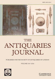
However, the emphasis on the shortcoming of Reid’s involvement has detracted attention from the significant influence that his scientific and medical background had on the design of the ventilation system or the empirical working methods that were used in its development.Footnote 23 He provided skills and perspectives that were distinct from those of civil engineers and architects. His perspective on architecture was characterised through a focus on environmental issues, human physiology and a scientific approach to ventilation exploiting the natural movement of air. In The Architecture of the Well-Tempered Environment, Reyner Banham wrote that medical doctors were instrumental in establishing early practices of building science,Footnote 24 and the Palace of Westminster could be interpreted as an attempt to integrate doctors into a larger cross-disciplinary design team. The letters and drawings used in the communication between Reid and Barry show that Reid’s main contribution was through the development of design concepts, underpinned by experimental enquiries inside the temporary Houses of Parliament. These enabled Reid to evaluate and refine ideas, utilising research methods he had deployed in early laboratory experiments in Edinburgh. Reid provided written specifications, sketches and schematic drawings to outline his concepts, but relied on the technical skills of staff in Barry’s office to develop his ideas on a technical level. This included the drafting of detailed construction drawings. In terms of his skills and knowledge, Reid therefore has a closer resemblance to a modern building scientist than a services engineer with a mechanical engineering background (fig 1).Footnote 25
Diagram illustrating how experiments with temporary structures have fed into the collaborative design process. Drawing: author.
REID’S FIRST SCHEME (1840–6)
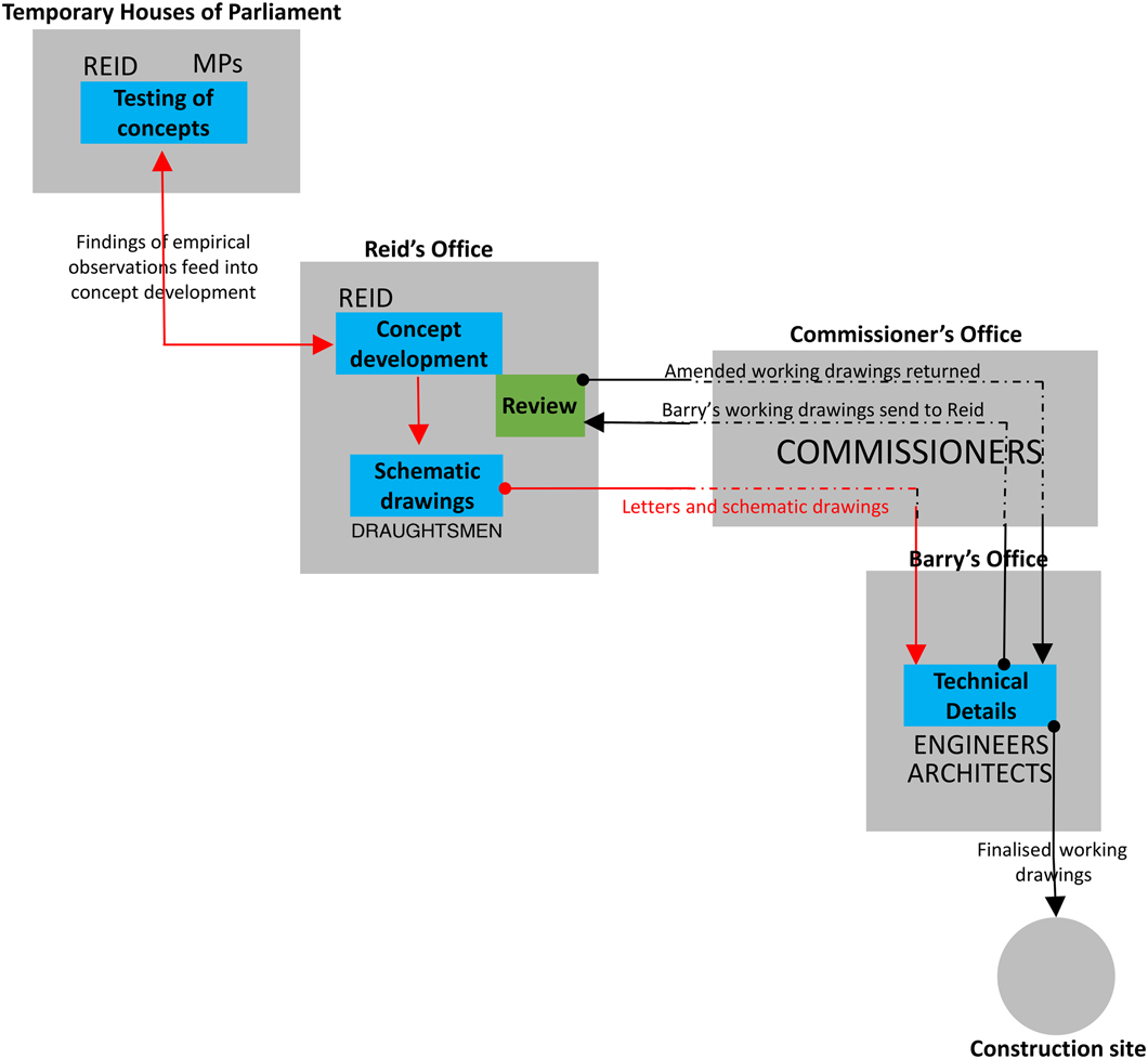
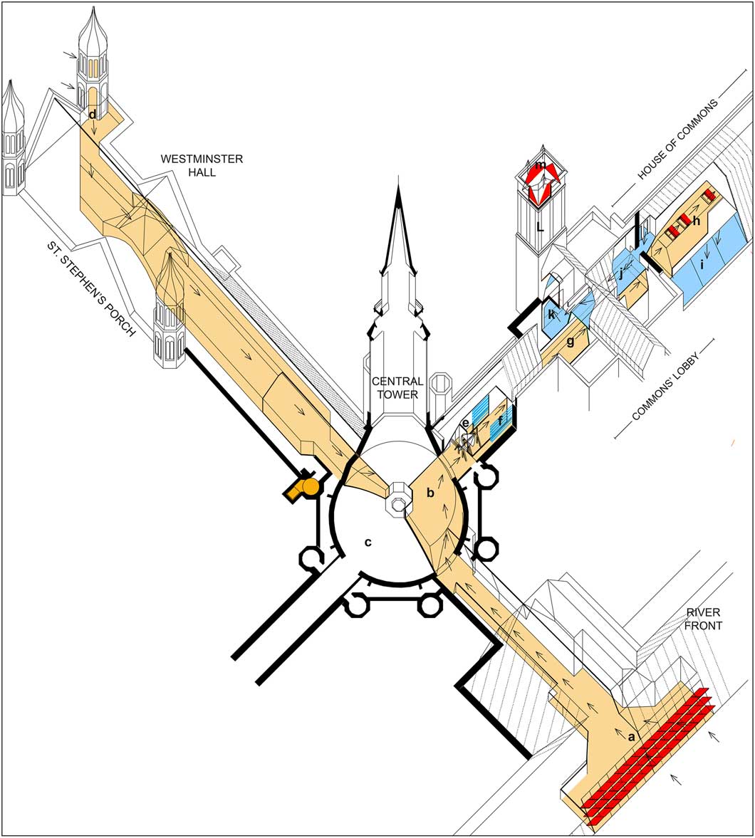
Although Reid’s early scheme was not realised, archival records provide significant insights into his original intentions. These records comprise original drawings and sketches as well as an extensive body of written evidence, including letters, reports and transcripts of interviews with several Select Committees between 1841 and 1846. The written communication between Reid, Barry and the Department of Woods and Forests shows that the ventilation scheme was conceived as a means of protecting parliament from the hazards of smoke pollution, which, alongside sanitation, was a major environmental health issue in nineteenth-century London.Footnote 26 Referring to observational studies on air pollution conducted in Westminster over the previous five years,Footnote 27 Reid argued that natural ventilation through openable windows was not feasible due to the severity of atmospheric pollution.Footnote 28 Instead, he proposed a hermetically sealed debating chamber that was integrated into a central ventilation system servicing the entire palace (fig 2).
Diagrammatic cross-section outlining the principle behind Reid’s proposed centralised ventilation system for the palace, 1840-46. Drawing: author. Key: a. inlet shafts inside Victoria Tower; b. fresh air passage linking inlets shaft of Victoria Tower to central air chamber; c. valve for fresh air supply from Victoria Tower; d. ‘central air chamber’; e. fans for supply to debating chambers; f. ‘directing flue’ to debating chambers; g. ‘heating chamber’; h. equalising chamber below main floor of debating chambers; i. ‘vitiated air chamber’ above ceiling; j. central up-cast shaft (smoke and air); k. inlet shaft inside Clock Tower; l. fresh air passage linking inlets shafts to central air chamber; m. valve for fresh supply from Clock Tower.
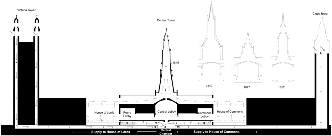
The air would be supplied centrally through a network of fresh air mains inside the basement and extracted through channels at roof level. These terminated inside a large shaft added above the vaulted ceiling of the Central Lobby. Fresh air for the central supply was introduced through three corner turrets in the Victoria Tower and one large shaft in the Clock Tower (fig 3a).Footnote 29 The purpose of the tall inlet shafts was to gain access to the atmosphere at a higher altitude, which Reid claimed to be less polluted than at ground level.Footnote 30 During an interview given to the Select Committee on Smoke Prevention (19 July 1843), Reid reported that the use of ground-level inlets in the temporary Houses of Parliament had caused difficulties with protecting the internal atmosphere from smoke pollution. On several occasions, he reported, MPs got sick when the atmosphere around the inlets was overly exposed.Footnote 31 The supply air had to be thoroughly filtered using canvas filters and water sprinklers.Footnote 32 As pollution levels varied locally depending on the wind direction, the Houses were also equipped with two separate inlets – one facing Cotton Garden, another facing Westminster Abbey – which could be swapped whenever the pollution around one inlet became too severe.Footnote 33 As pollution levels at the top of each tower also varied depending on the wind direction, Reid intended to adopt a similar system for the palace’s fresh air supply. This was intended to rely on only one tower at time. For this purpose, the Clock and Victoria Towers were linked at basement level through a ‘central air chamber’, which was equipped with valves to switch inlets depending on the state of the atmosphere at opposite ends of the site (fig 3b).Footnote 34
a) Plan of basement as proposed in Reid’s original scheme (1840–6), showing supply air passages (blue) by which the Clock Tower and Victoria Tower were to be linked to the central air chamber, and the main fresh passages (yellow) for distributing the air throughout the palace; b) plan of basement showing divided air supply adopted after 1846. Drawings: author. Key: A. Barry’s side of the central air chamber; B. Reid’s side of the central air chamber; 1. back-up inlets for House of Commons floor system, inside the central air chamber; 2. main inlets for House of Commons floor system, inside Clock Tower; 3. air passage connecting two inlets with House of Commons; 4. main inlet for House of Lords, inside Victoria Tower; 5. air supply passage to the central air chamber; 6. heating and humidification system inside the central air chamber; 7. distribution channel to St Stephen’s Porch; 8. distribution channel to river front; 9. House of Commons debating chamber (above); 10. House of Lords debating chamber (above).
This level of attention to issues of air pollution was the reflection of Reid’s wider engagement in issues of public health. While working in Westminster, he also contributed to studies of air pollution in major industrial cities and its health implications.Footnote 35 Between 1844 and 1845 he was a member of the commissioners for inquiring into the state of large towns and populous districts, undertaking large surveys of industrial towns,Footnote 36 and in 1843 he advised the Select Committee on Smoke Prevention on strategies for reducing atmospheric pollution.Footnote 37 His suggestions included measures addressing the root causes of pollution, such as the use of fuel efficient technologies and cleaner fuels, and solutions addressing the symptoms, for example, air filtration and the displacement of pollution through large chimneys.
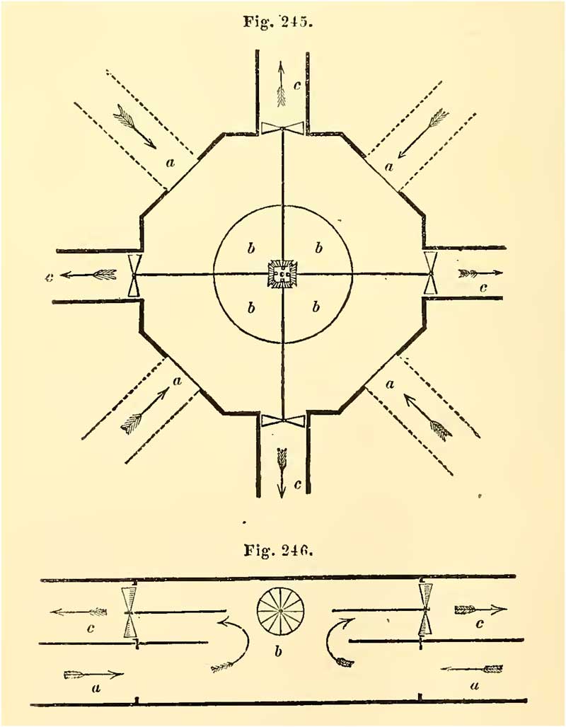
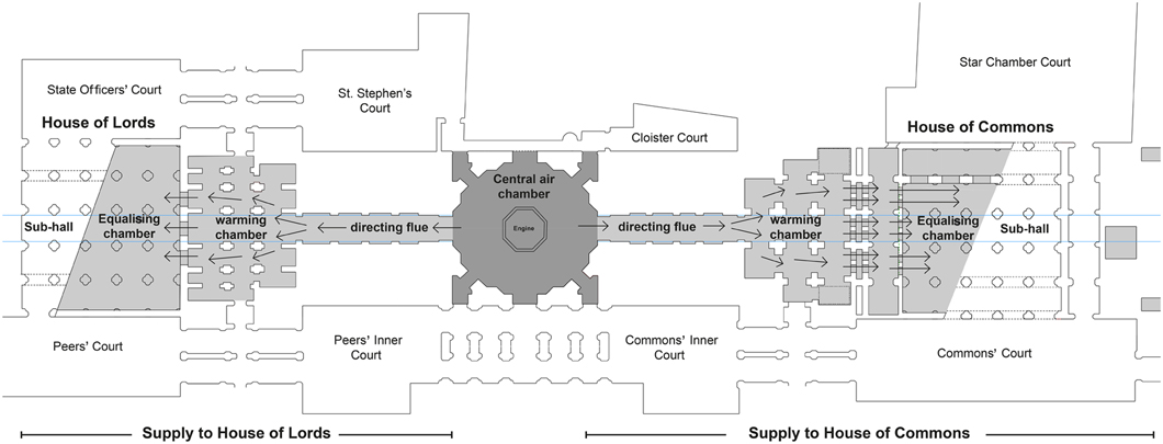
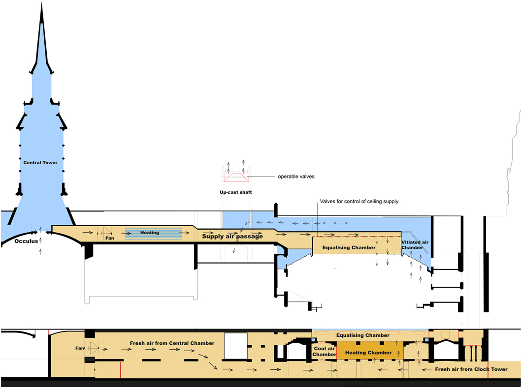
The fresh air entering the central chamber would be distributed internally via a network of ‘air mains’ with the assistance of steam-powered fans (fig 4).Footnote 38 The chamber was linked to four principal mains: two at basement level leading towards St Stephen’s in the west and the river front in the east, and another two on the ground floor serving the debating chambers (fig 5). The fresh air for the House of Commons left the central chamber through a large circular valve on the north side, which measured 12ft in diameter. Behind this valve was a large horizontal flue taking the air into the ‘heating chamber’ below the Commons Lobby (fig 6).Footnote 39 Passing through another set of circular valves at the north side of the heating chamber, the conditioned air entered the ‘equalizing chamber’ below the floor of the debating chamber.Footnote 40 The equalising chamber was provided to adjust temperature and humidity before the air was admitted into the debating chamber through openings in the floor, gallery and ceiling.Footnote 41
Diagrammatic plan and cross-section outlining the concept behind the central air chamber that Reid had proposed to distribute air throughout the Palace of Westminster, by Reid (Reference Reid1844, 332). Photograph: © Cambridge University Library.
Plan of ground floor showing fresh air supply from the central chamber to the Houses of Lords and Commons according to Reid’s original scheme, 1840–6. Drawing: author.
Longitudinal section through the House of Commons debating chamber, showing shafts and channels for supply and extraction of air, by Reid, 11 October 1845, PRO, Work: 29/2891. Photograph: © National Archives, Kew.
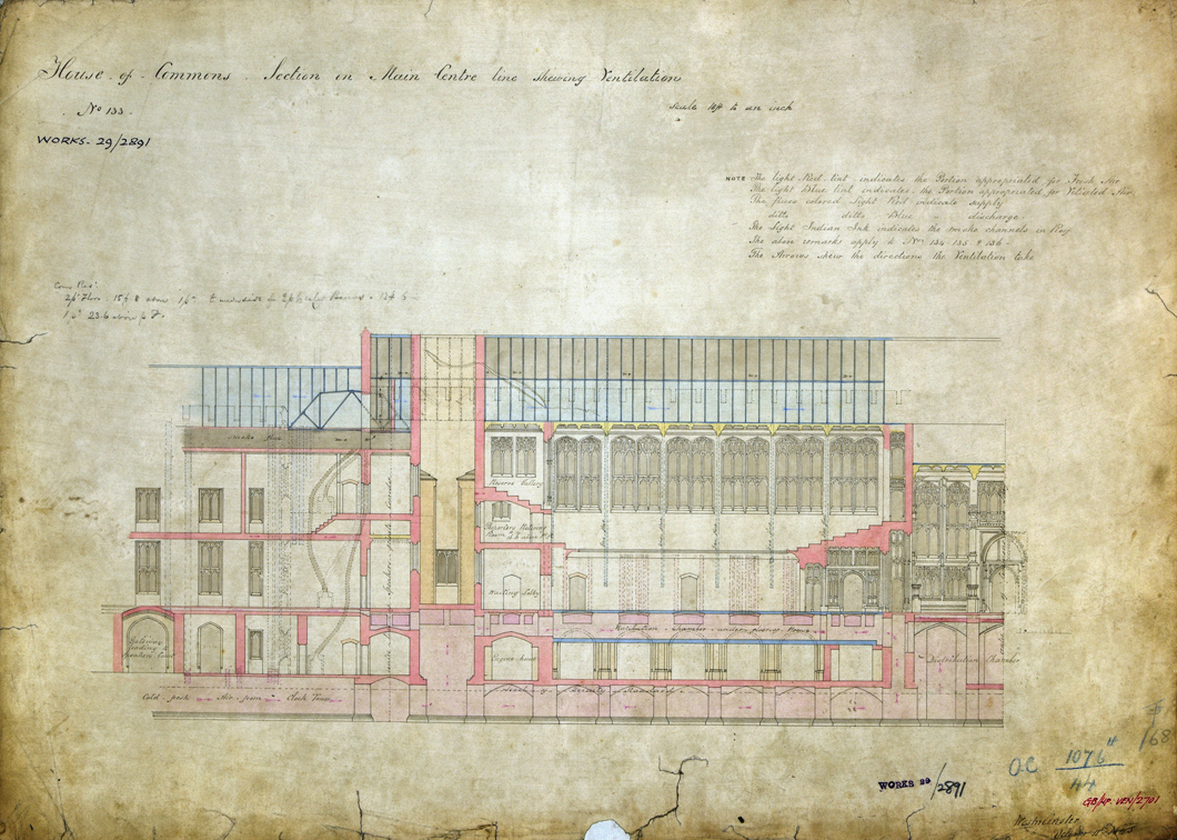
This arrangement followed the principle of a warm-air central heating system, which was already a well-established technology by the 1830s,Footnote 42 but Reid’s objective was to implement a form of air-conditioning that had been tested at a smaller scale inside the temporary House of Commons. This system combined warm-air central heating with facilities for cooling and humidity control.Footnote 43 Neil Sturrock and Peter Lawson-Smith (2006) argue that this was one of earliest demonstrations of the principle of air-conditioning.Footnote 44 In contrast to modern air-conditioning, invented by Willis Carrier in the early 1900s,Footnote 45 it relied on the use of passive, non-mechanical methods of cooling. According to an interview with the Select Committee on Ventilation of the New Houses of Parliament, the plan was to exploit the natural capacity of stone to absorb heat by exposing the supply air to the masonry of the vaults and paved floors inside the basement.Footnote 46 Reid argued that it provided an economical method of cooling at a large scale. Cooling methods involved passing air through nets filled with ice, as trialled inside the temporary Houses but not viable due to the cost and limited availability of natural ice.Footnote 47 The arrows shown on a cross-section of the House of Commons, dated 11 October 1845,Footnote 48 indicate that cool air could be admitted directly from the basement into the equalising chamber using vertical ‘ascending shafts’ at the south and north ends of the House. Equipped with adjustable valves, these shafts allowed the cool air to by-pass the heating chamber or to mix cool and warm air (see fig 6).
HARNESSING NATURAL PRINCIPLES
The vitiated air of the House of Commons was extracted through the Central Tower, which acted as the central up-cast shaft for the whole palace. In contrast to the Victoria Tower and Clock Tower, the Central Tower had not been part of Barry’s original architectural plans. It was added retrospectively and, as the cost for the tower was not covered by the original budget approved by the Treasury in 1836, his scheme underwent extensive review. In several oral reports to the Select Committee on Ventilation between 1841 and 1842, Reid argued that the tower had two important functions.Footnote 49 The first was to protect the atmosphere around the palace from its own emission by discharging the smoke of its several hundred fireplaces at a high altitude. His second objective was to eliminate the high running costs of mechanically operated systems by harnessing natural convection and wind pressure. The use of fires or fans was to be limited to periods when adequate ventilation could not be sustained through the ‘natural impulse of the air as introduced by currents of wind, and the natural tendency of hot and vitiated atmosphere to escape’.Footnote 50 He claimed that its effectiveness relied on the height of the shaft and, between 1841 and 1843, he proposed towers ranging from 150ft to 250ft in height.Footnote 51 These were also moved to an elevated position above the roof so that hot air could rise more naturally into the shaft. The buoyancy within the shaft was to be maintained by exploiting body warmth and waste heat from smoke (fireplaces and boilers), gas fumes (lighting) or kitchens.Footnote 52 Ventilating fires were only to be deployed temporarily to boost the ventilation, typically when the House got crowded or during summer, when the quantity of waste heat was limited.Footnote 53 To convey the vitiated air and fumes of several hundred rooms into the Central Tower, Reid planned an extensive network of large flues, which were situated below the roof.Footnote 54
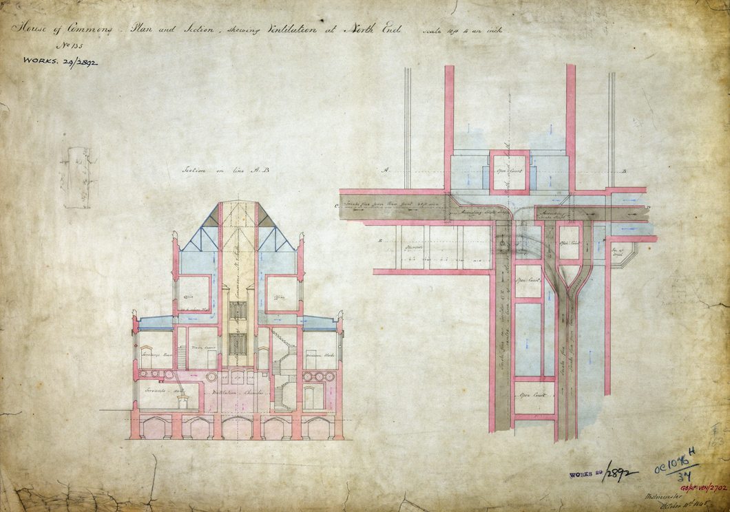
The original cross-section and plans illustrate how the House of Commons was intended to be integrated into this system. The hot air from the debating chamber and division lobbies was collected inside the ‘vitiated air chamber’ above the ceiling,Footnote 55 which was connected to the bottom of the Central Tower through a horizontal air channel (fig 7). The smoke channels were located on the floor above the vitiated air chamber. Conscious that the pull of the Central Tower would not be sufficient to ventilate several hundred rooms simultaneously, Reid introduced valves that permitted individual spaces, including the debating chambers, to be switched to the shaft whenever they were occupied.Footnote 56
Plan and cross-section showing the vitiated air (blue) and smoke (grey) channels above the ceiling of the House of Commons, north end, by Reid, 11 October 1845: PRO, Work: 29/2892. Photograph: © National Archives, Kew.
This shows that Reid’s proposal was based on a highly developed understanding of the capabilities as well as the limitations of natural ventilation utilising convection or wind pressure, which Reid also described in several textbooks.Footnote 57 In Rudiments of Chemistry (1836) and Elements of Practical Chemistry (1830), he introduced the science behind the natural movement of air induced by atmospheric pressure, gravity or thermal buoyancy. He also demonstrated how it can be studied experimentally in the laboratory or exploited in buildings to drive ventilation.Footnote 58 The application of such natural principles was not limited to the design of the up-cast shaft. Reid also spoke of the possibility of reducing the use of fan-driven supplies by exploiting the wind, whenever available, to deliver fresh air into the basement.Footnote 59 As such, it has close resemblance to the ‘mixed-mode’ approach used in modern sustainable buildings, such as the Weber Centre, Judson College, Chicago,Footnote 60 where mechanical services are utilised to complement, not replace, natural principles. This reinforces Vida Lerum’s argument that nineteenth-century architecture can provide potential lessons for sustainable environmental design in the twenty-first century.Footnote 61
THE CHALLENGE OF ACCOMPLISHING A COMFORTABLE DEBATING CHAMBER
The proposal for an air-conditioned debating chamber described in the previous section formed part of a more complex system of climatic control that Reid had developed to enhance thermal comfort. It was the culmination of detailed studies of MPs’ perception of indoor climates and air quality inside the two temporary chambers. These studies, which drew on research methods used by Reid in early laboratory experiments in Edinburgh, show most clearly how his medical background had shaped the perspective and working methods underlying the design of the ventilation system. Detailed accounts of these early experiments were published in two books, Illustrations of the Theory and Practice of Ventilation (1844) and Ventilation in American Dwellings (1858), and in several lectures.Footnote 62
One series of these experiments examined the physiological effect of air purity and climates. Volunteers were exposed to different climatic conditions and atmospheres of varying air quality, then interviewed on how these affected their concentration, appetite or physical well-being.Footnote 63 Similar methods were used to empirically evaluate and refine technical solutions. In the lectures, Progress of Architecture (1856) and The Revision of Architecture in Connection with the Useful Arts (1855), Reid described experimental rooms he had erected to study ways of diffusing air currents, with different configurations of perforated walls, floors or ceilings.Footnote 64 Volunteers were placed inside these rooms to provide feedback on the thermal sensations produced by the incoming air currents and how these were affected by velocity, temperature or humidity. A similar approach was used in the model of the debating chamber to examine how the higher ventilation rates – necessary to maintain good air quality standards under crowded conditions – could be achieved without causing uncomfortable draughts.Footnote 65 As before, its evaluation was based on the self-reported experience of volunteers.Footnote 66 It demonstrated that higher ventilation rates were achievable if the system switched from an upward supply through the perforated floor to a downward supply from the ceiling.
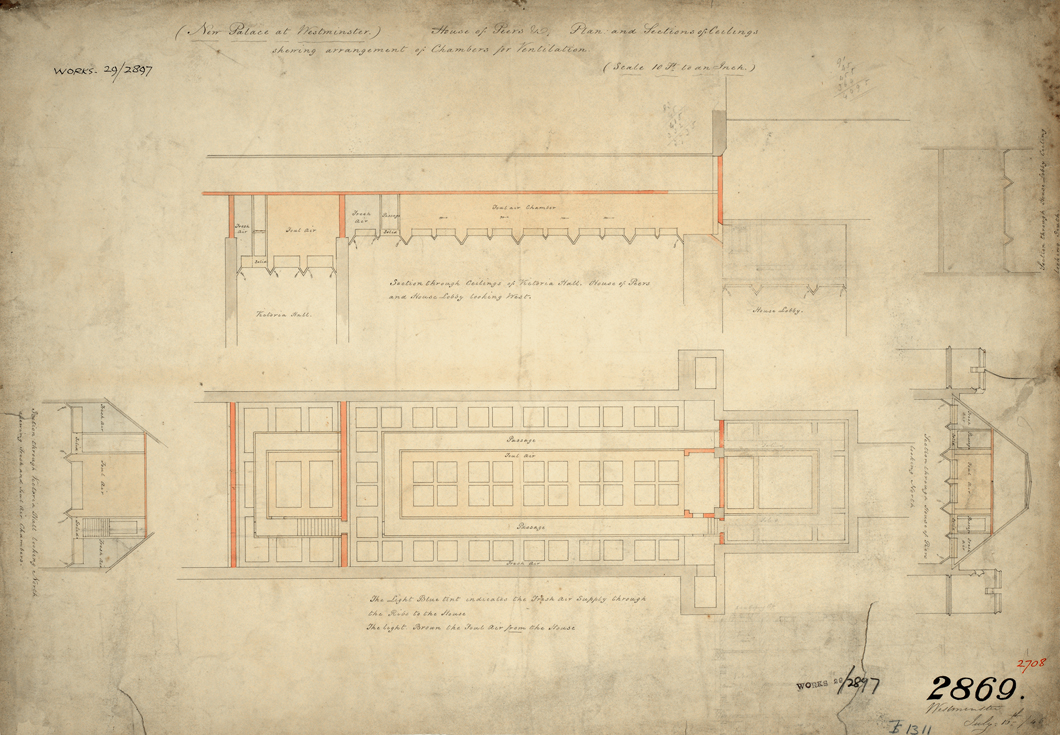
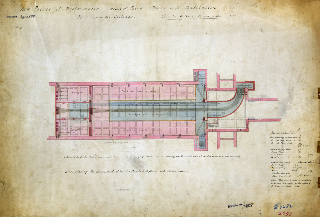
Tests continued inside the two debating chambers of the temporary Houses of Parliament, but this time under real-life conditions and involving MPs and lords, not volunteers. In the temporary House of Commons, where Reid was unable to implement a switchable supply, the air was continually supplied upwards through a perforated floor. According to interviews with MPs, this resulted in problems with cold feet and legs, which became particularly severe during crowded debates when the ventilation rate was boosted to prevent overheating and to maintain a fresh atmosphere.Footnote 67 In his scheme for the permanent Houses of Commons and Lords, Reid proposed to address this issue by returning to more complex arrangements that permitted air to be supplied and extracted at floor and ceiling level (fig 8).Footnote 68 Sketches produced between January and October 1845 outline proposals for the ceiling of the House of Lords (fig 9).Footnote 69 These show a chamber for the extraction of vitiated air above the central row of ceiling panels, which was connected to the Central Tower.Footnote 70 Fresh air, which was supplied from the basement through a vertical shaft, was introduced through the side panels.Footnote 71
Sketch of proposal for the supplying and extracting of air through the ceiling, by Reid, 16 July 1845, PRO: Works 29/2897. Photograph: © National Archives, Kew.
Schematic drawing of proposed air chambers above the ceiling of the House of Lords, by Reid, Reference Reid1845, PRO: Work 29/2888. Photograph: © National Archives, Kew.
In the temporary House of Commons, MPs were actively involved in evaluating the artificial climate within the debating chamber.Footnote 72 By pinpointing difficulties in achieving the right conditions, their feedback informed Reid’s effort to refine his system.Footnote 73 To gain tighter control over different climatic factors affecting thermal comfort, his system evolved into something more complex that incorporated a form of air-conditioning and sophisticated methods of environmental monitoring. The latter combined the recording with physical measurements and MPs’ feedback. The attendants working the ventilation continually engaged with MPs, acquiring an intimate understanding of their response to various environmental stimuli. Being a psychological state, thermal comfort was not directly measurable through scientific instruments, but required qualitative methods. Reid noted that it allowed gathering ‘information as to the ever-changing feelings of members, of which no one can possibly judge but themselves’.Footnote 74 In Illustrations of the Theory and Practice of Ventilation, Reid highlighted that thermal comfort was not only affected by environmental, but also personal, factors such as clothing, health conditions or the level of physical activity.Footnote 75
Demonstrating a methodology by which the perceived reality could be continually ‘metered’ alongside the measuring of physical stimuli, this monitoring system could be considered an early example of psychophysical principles being applied to architecture. Reid’s perspective resembles very closely what the German scientist Gustav Fechner described as äussere psychophysik (outer psychophysics). In Elemente der Psychophysik, published in 1860, Fechner described outer psychophysics as a scientific field concerned with the correlation between physical stimuli (äusserer reiz) within the environment and the sensations (innere empfindung) they produce.Footnote 76 Although his approach was less systematic than Fechner’s later method, Reid reviewed these self-reported experiences to determine how one’s perception of thermal comfort might be affected by climatic conditions. Analysing several years of user-responses and measured data collected inside the temporary House of Commons, he attempted to determine the conditions in which the majority of MPs felt comfortable. Reid wrote:
as far as I have been able to observe, a temperature of 65F, with an atmosphere moving in a very gentle stream, so as not to be perceptible, is the most agreeable in rooms that are not overcrowded.
Referring to humidity, he reported:
when there is a difference between 5F between the dry thermometer and wet-bulb thermometer next to it, I have the least number of complaints.Footnote 77
Managing a climate based on experience was a difficult process due to conflicting feedback from different MPs. Reid reported that there was:
scarcely a meeting of the House at which there are not some Members who would like the temperature to be at 55F degrees, and others at 70F or 72F.Footnote 78
It required the Sergeant-at-Arms, Sir William Gosset, to moderate the responses of individual MPs. In 1839, Gosset wrote:
sometimes Members come to me, and say the House is very hot, or very cold; I look at the thermometer, and see if so, for different people have different feelings with regard to temperature. People come in very hot, and say, ‘How cold the House strikes’, and another man says ‘I have been sitting here half an hour, and I am in fever’, and if I see the thermometers are too high or too low, I give directions accordinglyFootnote 79
Starting in 1838 Reid used the temporary House of Lords to test an alternative approach to climate control. He explored how far thermal comfort could be improved if the interior was divided into different climate zones instead of being uniform.Footnote 80 Crowded areas, being more likely to experience overheating, were supplied with cooler air than more sparsely populated areas. The temperature in one section could be as low as 52°F and as high as 75°F in another. In the House of Commons, Reid and the Sergeant-at-Arms reported that it was difficult to achieve a consensus among MPs when the climate was uniform, making climate control a political struggle. Continuous attempts were made to manage the shared climate according to the preference of the majority, while dealing with a few individuals who were vocal about their dissatisfaction.Footnote 81 Reid noted that the:
only alternative has frequently been to make a local change under the benches occupied by them [certain individuals] or suit their convenience at the expense of incommoding the House generally, unless they were left subject to an amount of annoyance of which they bitterly complained, for the state of the air being more congenial to those around them than to themselves.
Eyewitness accounts given by the Lords between 1838 and 1846 suggest that the new approach had failed to achieve a more comfortable environment. Lord Campbell wrote in September 1843 that while the air quality had improved, the Lords suffered from a lack of control over temperatures and currents.Footnote 82 During one debate (February 1843), he complained that the ‘alternate heat and cold of the place made it at one time a cold bath, and at another a vapour bath’.Footnote 83 In June 1845, Lord Brougham and the Marquess of Clanricarde complained about the ‘wretched state’ of the atmosphere and Campbell noted that some peers ‘suffered so severely last night from the imperfect ventilation, and the sudden draughts of hot and cold air’.Footnote 84 On 24 April 1846, Brougham described the chamber as ‘sometimes broiling and sometimes freezing’,Footnote 85 and the next month Campbell noted that ‘nothing could be more detestable than the result of the learned doctor’s experiments in their Lordships’ House’.Footnote 86 Despite wide disapproval, Reid followed the same concept in his plans for the permanent Houses of Lords and Commons. He argued that the technical arrangements had been constrained by funding, but the main issue was insufficient co-operation, with the Lords not providing the regular feedback necessary to implement the idea of a responsive system.Footnote 87
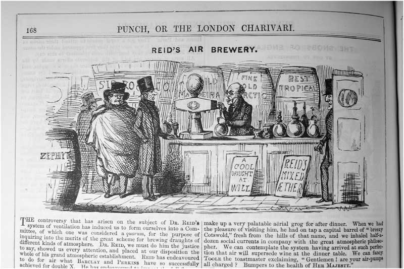
In several interviews, Reid described how he intended to apply the concept to the permanent House of Lords. The interior was to be divided into five climatic zones, located around the ministerial and opposition benches, throne, bar and within the central floor. In each zone, the climate and air supply would be regulated according to the number of peers present, but in addition each bench would be equipped with a separate supply to achieve a greater level of local control.Footnote 88 These supplies were only to be activated by the attendants on request, and individual control was limited to peers who had to sit inside the chamber for extended periods. Reid’s objective was to give ‘all who are tied down to official seats a ventilation in unison with their own feelings to a certain extent, while the general ventilation is arranged for the House’.Footnote 89 The satirical magazine Punch likened Reid’s system to a brewery, offering members ‘draughts of different kinds of atmosphere’ (fig 10).Footnote 90
Cartoon published in Punch using a brewery as an analogy for Reid’s concepts of locally tailored climates. Source: Punch, 18 April 1846, reproduced with permission of British Cartoon Archive, University of Kent.
THE HOUSE OF COMMONS BECOMES AN INDEPENDENT SYSTEM
The correspondence shows that efforts to apply Reid’s ventilation scheme were undermined by difficulties in achieving a successful collaboration between Reid and Barry. From 1844 to 1845, Reid and Barry had several disputes, including: the cross-section of the Central Tower;Footnote 91 the use of roof spaces for conveying air and smoke to the Central Tower;Footnote 92 and potential fire risks.Footnote 93 Despite several attempts by the Department of Woods and Forests to moderate the negotiations, these difficulties remained unresolved and Reid’s scheme was finally abandoned in autumn 1846, following a parliamentary inquiry.
Having caused delays and rising costs, several reviews of the impact of Reid’s involvement were undertaken between 1845 and 1846. It involved two Select Committees, appointed by the House of Lords and Commons, respectively,Footnote 94 and an independent review of Reid’s working methods by the architect Joseph Gwilt.Footnote 95 Barry, Reid and Alexander Milne, First Commissioner of Woods and Forests, were interviewed about the process, which revealed that Reid’s ability to collaborate with the architect and his engineers had been compromised by insufficient drafting skills and experience with architectural design as a process. While he had deep knowledge of general scientific principles, his experience with translating these principles into technical solutions or incorporating them into architectural plans was limited.
Goldsworthy Gurney, a physician and expert in the ventilation of mines and sewers, also questioned the technical feasibility of Reid’s scheme.Footnote 96 He challenged it in a petition read at both Houses in April 1846.Footnote 97 Claiming that the palace was too large to be ventilated by a single chimney,Footnote 98 he proposed to replace it with a system of local shafts.Footnote 99 The Department of Woods appointed three referees – the engineer George Stephenson, the architect Phillip Hardwick and the chemist Thomas Graham – to review these claims.Footnote 100 They approved his critique, arguing that the centralised scheme, if applied to the entire palace, would become overwhelmingly complex, and that it could be simplified by using a series of smaller up-cast shafts. Barry also offered to take on the responsibility of ventilating the House of Lords, guaranteeing completion in 1847 if done without Reid’s interference. The committee accepted his proposal in August 1846, arguing that further delays in the completion of the House could be prevented if Barry’s office was given full control over all aspects of the design.Footnote 101
REID’S FINAL DESIGN (1847–52)
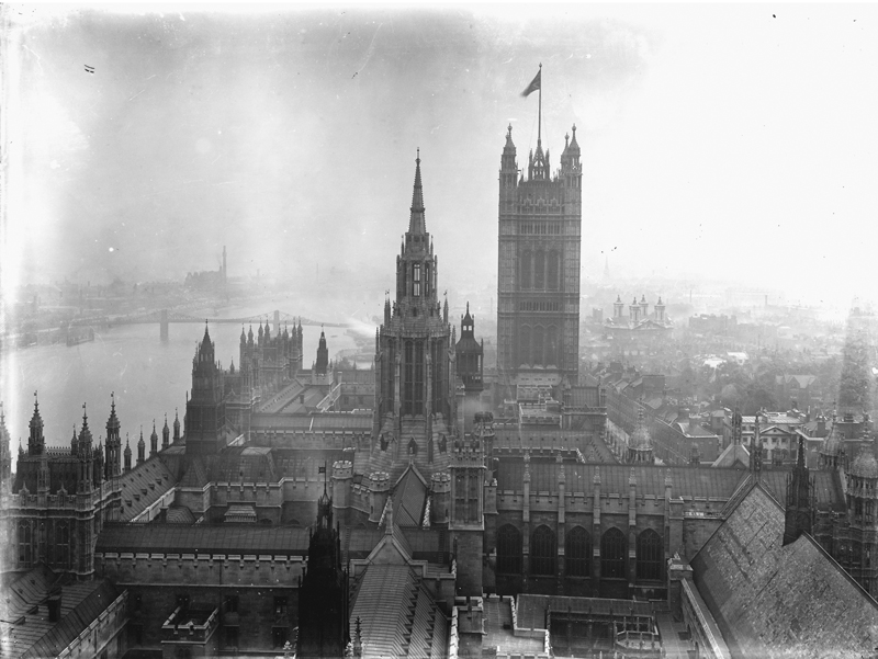
Reid’s masterplan was abandoned in September 1846 and the ventilation was reorganised following the referees’ proposal for a decentralised strategy. Reid’s responsibility was confined to the House of Commons,Footnote 102 a decision that Reid challenged by undertaking several unsuccessful attempts to get parliament to review the decision.Footnote 103 His new territory extended from the north end of the Central Hall to the corridor behind the Speaker’s chair and included the Commons’ lobby and division corridors.Footnote 104 The ventilation in other parts of the palace, including the House of Lords, came under Barry’s control. Assisted by his engineers, Alfred Meeson and William Jeakes, and involving Michael Faraday as technical adviser, Barry developed a new system. The concept of a central up-cast shaft was abandoned and replaced by several local shafts, which had the external appearance of Gothic spires.Footnote 105 Added gradually between 1847 and 1855, these shafts resulted in a significant architectural transformation of the roof-scape (fig 11).
Aerial view of the Houses of Parliament (looking eastwards) showing the position of local ventilation shafts introduced by Reid and Barry after abandoning the central up-cast shaft in 1846, c 1900, PED: Farmer 743. Photograph: © Parliamentary Estates Directorate.
On 5 April 1847, he send a set of over forty drawings to the Office of Woods, outlining a new scheme for the House of Commons that still adhered to his earlier concepts. Some features that were already completed according to his original plans were re-used.Footnote 106 These included the equalising chamber, supply ducts for the east and west galleriesFootnote 107 and the four large shafts supplying the galleries at the north end.Footnote 108 Other features, including the air supply, had to be re-modelled as the House was no longer integrated into the palace’s central supply and discharge system. It had to work as an independent system. The ventilation at ceiling and floor level were designed as separate systems, each equipped with its own set of fresh air inlets, up-cast shafts and climatic control arrangements (fig 12).
Cross-section, showing ceiling and floor systems implemented between 1847 and 1852. Drawing: author.
THE CEILING SYSTEM
Reid’s new design was implemented between May 1847 and February 1852, but the plans underwent several modifications. The design of key features, such as the air supply for the ceiling inlets, was the outcome of intense negotiations involving Reid, Barry and several committees. Although his involvement had been restricted to the House of Commons, Reid still required Barry’s approval for critical features of his system. The disagreements over design decisions continued and in 1848 the Office of Woods appointed a commission to supervise the communication between Barry and Reid.Footnote 109
In spring 1847, Barry reduced the height of the Central Tower.Footnote 110 He argued that the great height of former designs for the tower was no longer required, for functional or architectural purposes.Footnote 111 Barry proposed converting it into a local shaft for the Lords. Initially, Reid had hoped to retain the tall tower as a fresh air inlet for the ceiling system, which could be operated independently from the floor system served by the Clock Tower.Footnote 112 Without access to the Central Tower, Reid introduced a new shaft on the west side of the Commons lobby.Footnote 113 In June 1848, following twelve months of intense negotiations, Reid and Barry agreed a new arrangement for the ceiling supply.Footnote 114 The primary inlet was embedded within the cast-iron roof facing the river and equipped with adjustable louvres.Footnote 115 When it was exposed to pollution, the supply was switched to a second inlet located within a turret at the north-west corner of St Stephen’s porch.Footnote 116 The fresh air was conveyed to the House through passages under the roof. The ceiling supply had its own fan and heating:Footnote 117 the fan was located at the north side of the Central Tower and air was warmed within a passage lined with steam pipes. This passage terminated in the fresh air chamber above the central ceiling panels (fig 13). Air was admitted into the debating chambers through gaps between the panels and openings inside hollow ornamental beams.Footnote 118 It was adjusted manually by means of sliding valves.Footnote 119
Axonometric projection outlining the ceiling system. Drawing: author. Key: a. principal air inlet of the ceiling system with adjustable cast-iron louvres; b. fresh air channel passing through Central Tower, with diagonal wall marking the boundary between Barry and Reid’s territory; c. area connected to the House of Lords (Barry); d. back-up inlet for ceiling system, inside turret; e. fan; f. steam pipes; g. supply passage leading to House of Commons; h. fresh air chamber above central ceiling panels of House of Commons; i. vitiated air chamber above sloping side panels of ceiling; j. passage connecting vitiated air chamber with up-cast shaft; k. base of up-cast shaft, with coke fire; L. up-cast shaft; m. louvres valves at outlet of up-cast shaft.
The vitiated air chamber, which was situated above the side panels, was connected to the new up-cast shaft. Air entered at the base of the shaft and was exhausted through cast-iron valves on the top that could be adjusted with the aid of pulleys.Footnote 120 The pull produced by the rising hot air, which at times was enhanced with coke fire, drove the vitiated air out of the debating chamber. As it was not strong enough to ventilate the debating chamber and lobbies simultaneously, valves were used to connect the shaft to individual spaces, including the Commons’ Lobby, the Ladies’ Gallery and the Strangers’ Gallery.Footnote 121 During votes, for instance, valves were switched to re-direct the pull from the House to the division lobbies.Footnote 122
THE FLOOR SYSTEM
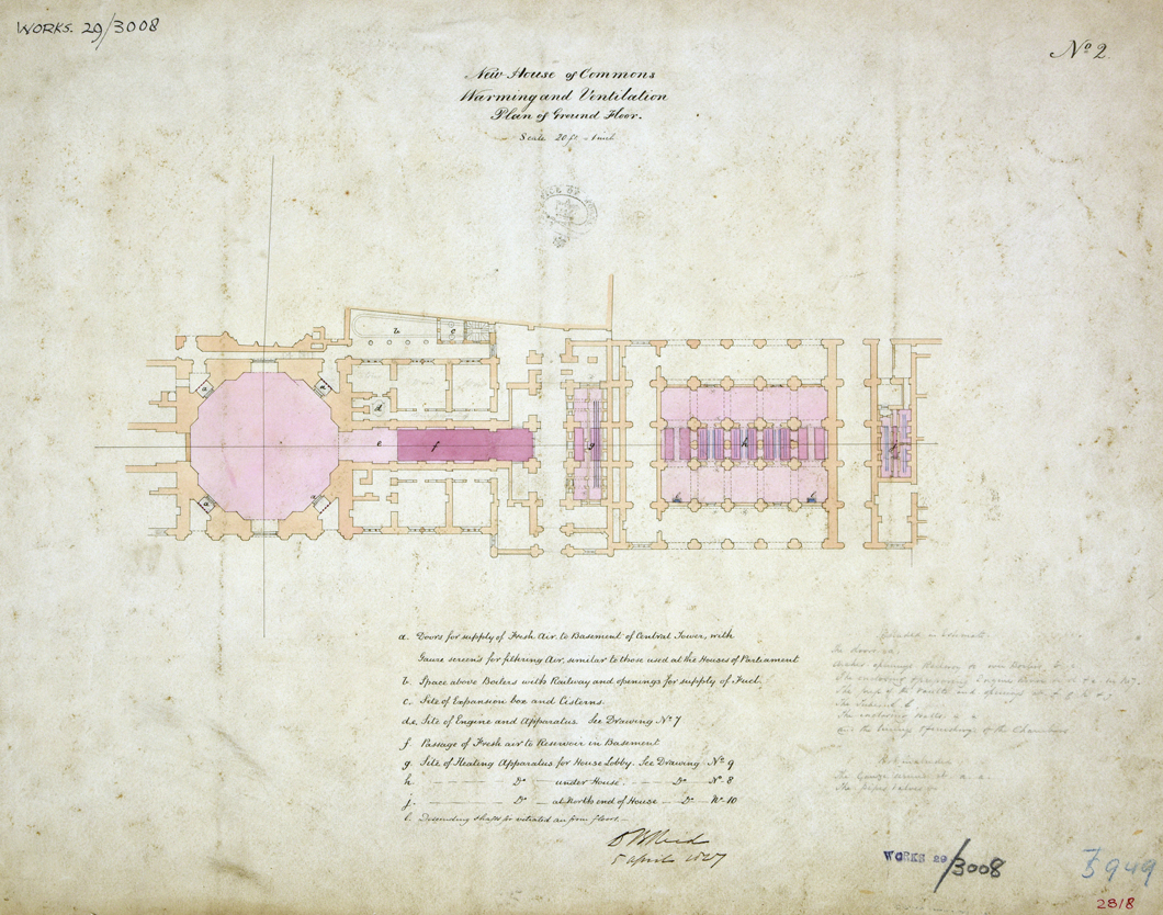
The territorial border drawn in 1846 required Reid to develop a new supply for the floor system. Barry retained parts of the centralised supply within his territory, using the Victoria Tower as the main inlet, but it was physically separated from the House of Commons. As the House had only access to the high-level inlet inside the Clock Tower, Reid adopted the central chamber as a new back-up for periods when the Clock Tower could not be deployed due to air pollution.Footnote 123 Mirroring the principles of the roof level inlets, the use of switchable inlets was part of Reid’s strategy to make the building more responsive to changing levels of air pollution. His initial plan was to use the whole central chamber to switch the supply between the four surrounding courts, depending on pollution levels (fig 14).Footnote 124 In July 1848, however, Barry subdivided the chamber because he required the south side for his own system (fig 15).
Sketch of ground floor showing original proposal for using the whole central chamber with its four inlets as back-up supply for the floor level system, by Reid, 5 April 1847, PRO: Work 29/3008. Photograph: © National Archives, Kew.
Plan of basement under House of Commons, showing system of fresh-air passages, including the central chamber with diagonal wall marking the boundary between Barry and Reid’s territory. Drawing: author. Key: 1. inlet shaft; 2. fresh air passages; 3. fresh air passages leading to the central chamber; 4. central chamber; back-up inlet inside central chamber, including one inlet facing Cloister Court (5) and another facing the Commons’ Inner Court (6); 7. air main leading from central chamber to House of Commons which contained valves (8) opening into the heating chamber above; 9. cold air passages that contained valves for admission of air into the cold air compartment above; 10. flue linking floor level extract to boiler flue (11); 12. Barry’s side of the central chamber with heating pipes.
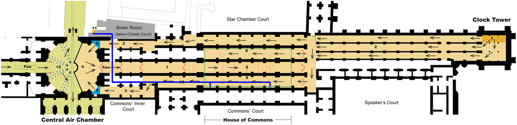
Within Barry’s territory, the fresh air admitted through the Victoria Tower was conveyed into the southern half of the chamber, where it was tempered using a heating and humidification system before entering the supply passages leading towards the river front, St Stephen’s Hall and the House of Lords.Footnote 125 As a result, Reid was left with only two apertures giving access to fresh air in the Cloister Court and Common Inner Court (fig 16).Footnote 126
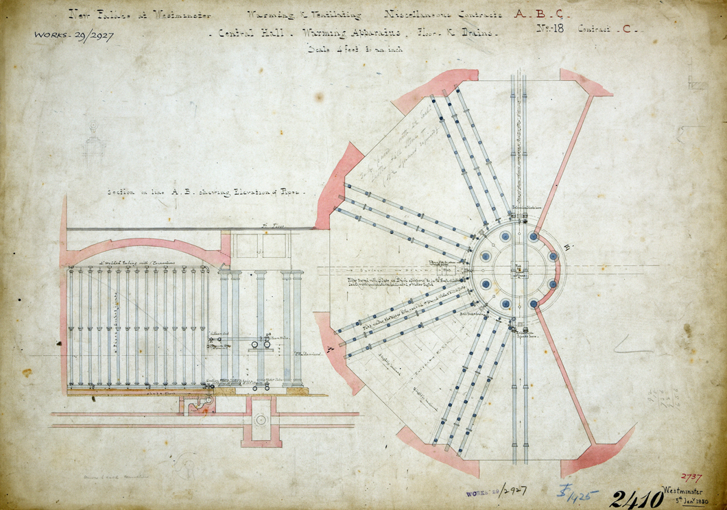
Plan and cross-section of steam pipes on Barry’s side of the central chamber, by C Barry, 5 January 1850, PRO: Work 29/2927. Photograph: © National Archives, Kew.
Within Reid’s territory, the air admitted through this central chamber or the Clock Tower was conveyed to the House through basement passages and ascended through ceiling valves into the heating and cool air chambers on the ground floor (fig 17).Footnote 127 Three rectangular valves were provided for the heating chamber, which was filled with hot-water pipes, and twelve circular valves provided for the cool air compartment surrounding the heating chamber. Footnote 128 At the next stage, the cool and heated air rose through separate valves into the equalising chamber. Temperature and relative humidity were monitored using a hygrometer and twenty thermometers.Footnote 129 The air was tempered using the air-conditioning system tested in the temporary House of Commons. The permanent chamber had facilities for cooling, heating, humidifying and dehumidifying the supply air.Footnote 130 The humidity of the supply air was raised with the aid of steam or by evaporating water, and was lowered using an ‘absorbent of moisture’, which Reid did not specify. Cooling was provided via passive, non-mechanical means. The supply air temperature was lowered by passing cold water through the heating pipes or, if the air was sufficiently dry, by evaporating distilled water. Ice – used for brief trials in the temporary House – was not deployed. In addition to lowering the actual air temperature, Reid exploited the cooling sensation produced by air currents passing over the human skin, which lowered the perceived temperature.
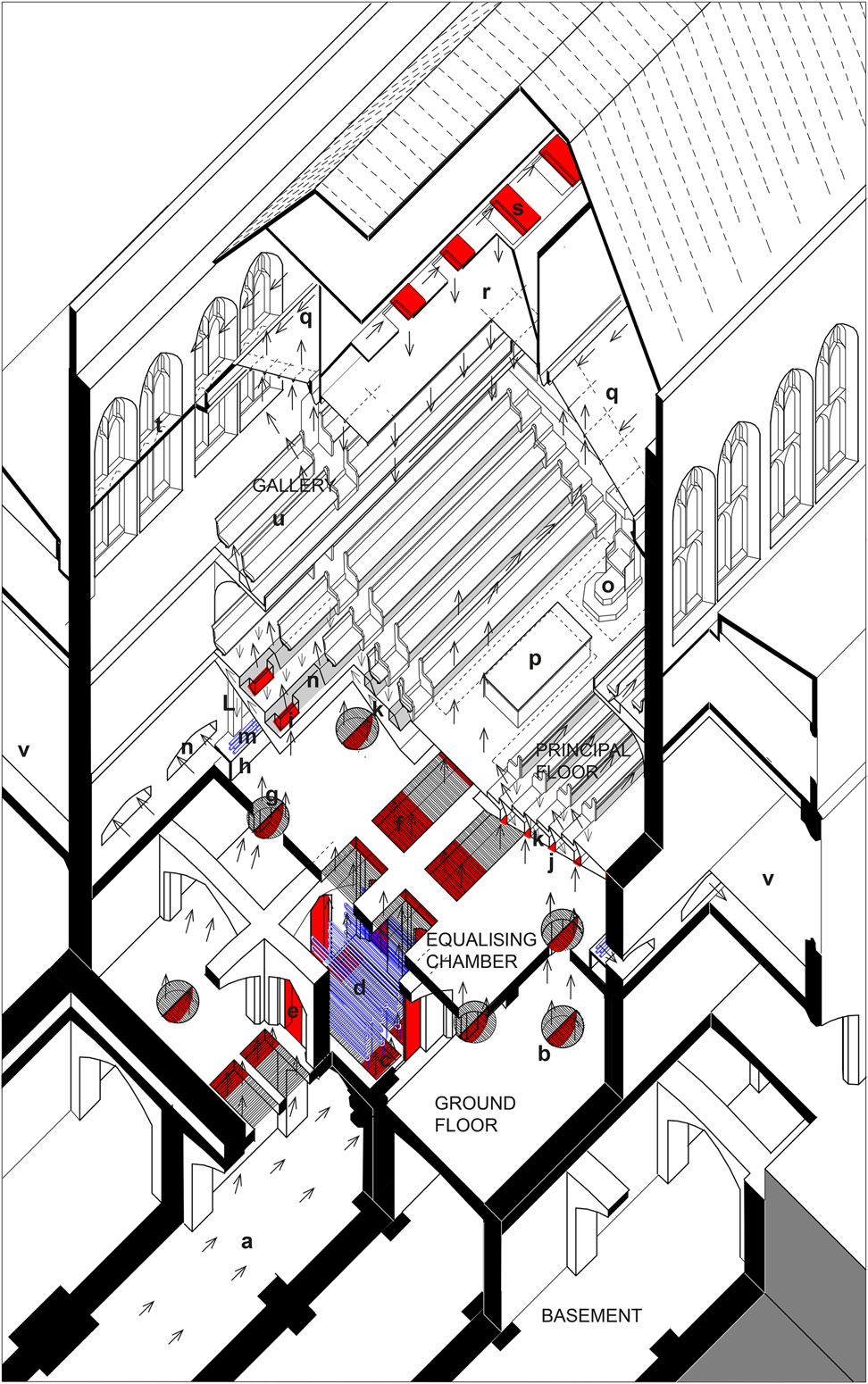
Axonometric projection of House of Commons debating chamber, showing the ventilation arrangement below the floor and above the ceiling. Drawing: author. Key: a. fresh air passage linking inlets shafts to central air chamber; b. valves for conveying air from basement into cool air chamber (circular valves with shutters, shown in open position); c. valves for conveying air from basement to central heating chamber (rectangular valves with adjustable curtains below grating, shown partially opened); d. pipes of hot-water apparatus in heating chamber; e. vertical door valves for conveying hot air into cool air chamber; f. rectangular curtain valve through which heat air was admitted into equalising chamber; g. circular shutter valves to admit unheated air from cool air chamber into equalising chamber; h. horizontal duct in which vitiated air extracted through perforated floor was collected before it exhausted via the boiler in north-west turrets of Central Tower; i. sliding valves for supply of individual benches; j. sliding valves for supply through treads inside the gangways; k. Vitiated air chamber under perforated iron floor (extract); L. vertical ducts connecting vitiated air chamber with horizontal ducts; m. steam and hot-water pipes (heating and humidification); n. valves conveying air to fresh air chamber under the perforated floor of the division lobbies; o. Speaker’s chair; p. table; q. vitiated air chamber above sloping side panels, extract of ceiling system; r. fresh air chamber used to supply tempered fresh air through central ceiling panels (ceiling system); s. sliding valves for regulating air supply to ceiling; t. line of acoustic ceiling retrofitted in 1851, covering half of Barry’s original window; u. gallery with air supply through floor; v. division lobbies.
In winter the supply air temperature was controlled by adjusting the temperature of the heating pipes, but a process of mixing heated and unheated air was used to lower the temperature in response to sudden changes in attendance. The valves above the heating chamber could be closed, and heated air re-directed into the surrounding cool air chamber.Footnote 131 When the House had to be cooled down more rapidly, the heating chamber was closed completely, and cool air admitted directly from the basement.
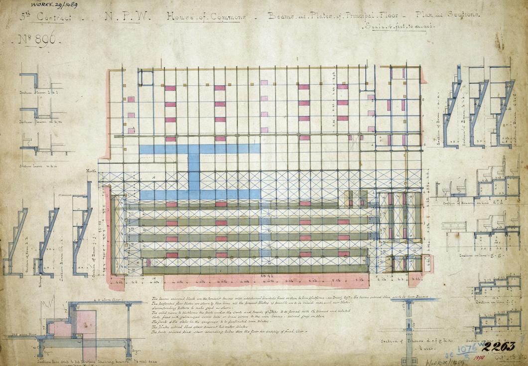
The floor was covered with perforated cast-iron plates, but, in contrast to the temporary House of Commons, where fresh air was admitted across the entire floor, it had outlets to extracted vitiated air downwards as well as inlets to supply fresh air upwards. Inlets were confined to areas where MPs were not exposed to currents. Air was supplied through the floor between the table and bar, risers in the gangwaysFootnote 132 and along the back of the benches. The chairs for the Speaker and Sergeant-at-Arms had individual supplies. The supplies could be adjusted individually by attendants inside the equalising chamber, using over sixty sliding valves. The inlet along the back of every bench had ducts with individual valves (fig 18).Footnote 133
Plans forming part of original working drawings produced in Charles Barry’s office, showing the hot-water plates and supply ducts for individual benches, by C Barry, 25 October 1850, PRO: Work 29/1489. Photograph: © National Archives, Kew.
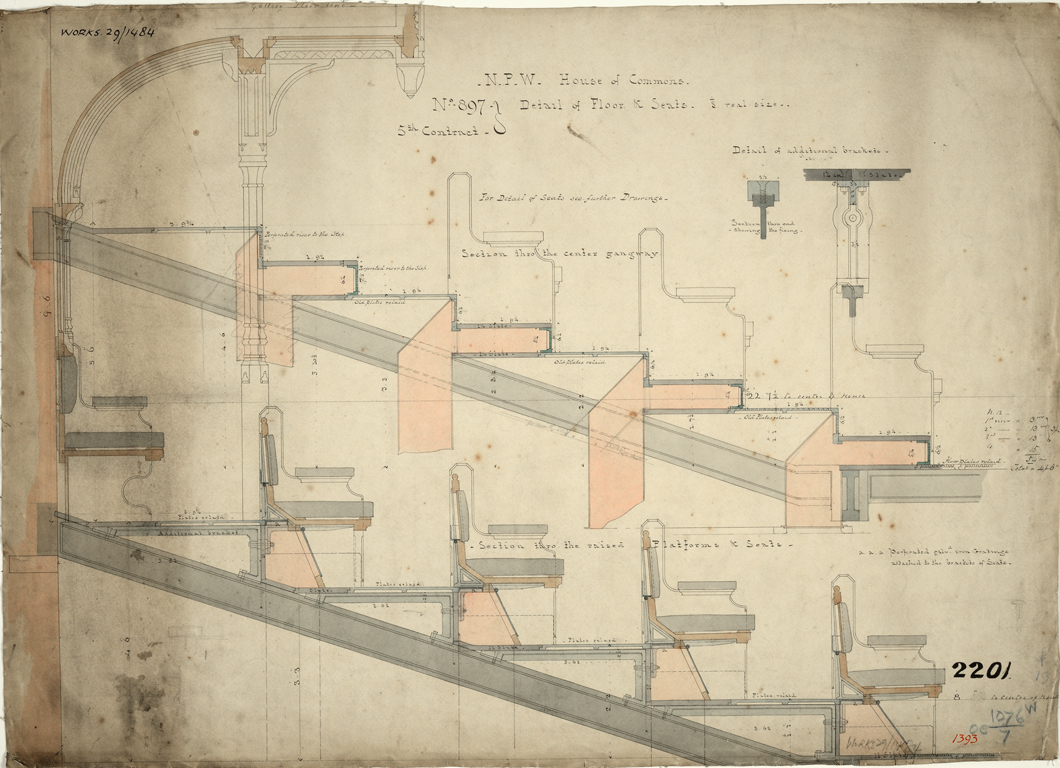
Some air was continuously extracted downwards through the floor immediately in front of the benches (fig 19).Footnote 134 This entered a vitiated air chamber below the floor and was discharged via the boiler chimney, which terminated in the turrets in the north-west corner of the Central Tower (fig 20).Footnote 135 Special provisions were made for enhancing the thermal comfort of front benchers, the Speaker and the Sergeant-at-Arms by warming their feet with hot-water plate radiators attached to the underside of the iron floor.Footnote 136
Construction details showing air supply within floor and benches, by Charles Barry, autumn 1850, PRO: Work 29/1484. Photograph: © National Archives, Kew.
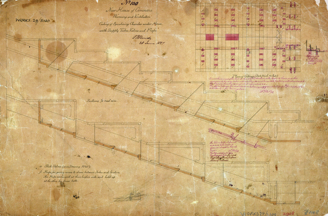
Drawings produced in Barry’s office in June 1851, which includes notes and sketches that Reid had added on 17 and 26 November to refine details of sliding valves, by C Barry and D Reid, PRO: Work 29/3100. Photograph: © National Archives, Kew.
ENVIRONMENTAL MONITORING
Between February 1852 and April 1854, the environmental system was systematically monitored as part of the day-to-day operational procedures. Fulfilling a similar role to the digital sensors of modern building management systems, the monitoring data was collected to provide the human operators with feedback on the system’s performance. Feedback was acquired through the recording of measurements, direct observations and by collecting personal responses from MPs (fig 21). Reid envisaged a system responsive to internal and external environmental conditions as well as the MPs’ personal experience.
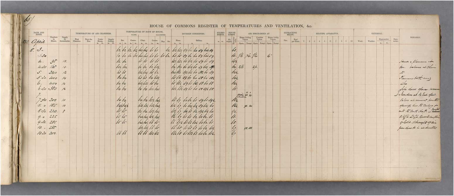
Page from the original logbook used to record monitoring data, 8 April 1853, Parliamentary Archives, Office of Works 1853–1947 OOW/5. Photograph: © Parliamentary Archives.
The monitoring followed the same principles as the monitoring regime tested inside the temporary House of Commons, and involved collecting subjective feedback alongside the recording of measurements. The attendants kept logbooks that contained registers for qualitative and quantitative data. These included columns for numerical data (temperature, humidity and air speed, number of MPs) and written notes referring to operational procedures and air quality, which was only monitored through direct observations – including detailed notes on how the supplies were switched in response to external air pollution. On 6 March 1854, for instance, attendants noted that the atmosphere was ‘very foggy and charged with smoke’ and that the supply was switched to central hall as ‘that from the Clock Tower very smoky’. These issues continued over two weeks and attendants wrote that switching the supply made the air ‘better but not good’. On one occasion, a ‘foggy atmosphere loaded with smoke of the neighbourhood penetrated the building’.
Within the debating chamber itself, only the air temperature was measured, using eight thermometers: four were fixed to the back wall of the galleries;Footnote 137 the other four were on the main floor, near the chairs of the Speaker and Sergeant-at-Arms and behind the benches on the opposition and government sides.Footnote 138 Inside the debating chamber, the messenger of the Sergeant-at-Arms recorded temperatures at hourly intervals and collected qualitative feedback from individual MPs.Footnote 139 Registers with the measured data were sent directly to the ventilator’s office, where it was transcribed into the central logbook and analysed. The MPs’ self-reported experience was carefully reviewed by the Sergeant-at-Arms, Lord Charles Russell, before the order was sent to the superintendent managing the attendants. Reid was the superintendent from February to November 1852, after which he was succeeded by the engineer Alfred Meeson. Russell reported that he was the ‘medium of communication, as respects the ventilation, between Dr. Reid and the Members’Footnote 140 and also highlighted that moderating the, often conflicting, response from individual MPs was a challenging process. References to orders and feedback can be found inside the logbooks.Footnote 141 On 13 April 1853, for instance, attendants wrote that the ‘Speaker complained of draughts round his head’. On 31 March it was noted that the Speaker felt ‘too warm’ and on 7 April the Sergeant-at-Arms ‘wished the House a little cooler’. The level of environmental monitoring that Reid had envisaged was highly ambitious and the logbooks show that the attendants rarely collected enough data to fill an entire sheet. The quantity of recorded data varied significantly between days. This is not surprising as the monitoring was a labour-intensive procedure. Each reading was recorded individually by hand without the assistance of automatic recording devices. To gain a full set of temperatures alone, attendants had to take over fifty readings per hour, each of which had to be manually logged at different locations. Reid was clearly aware of this issue because he proposed introducing ropes and pulleys to operate dampers remotely, and speaking tubes and bells to improve communication between attendants and the ventilation office.Footnote 142
THE POST-OCCUPANCY HISTORY OF THE HOUSE OF COMMONS
‘thermometer tells one tale, and the human body tells another’
John Leslie 1852Footnote 143
The previous sections have illustrated how the environmental principles adopted in the House of Commons reflected a deep concern about the MPs’ perceived thermal comfort, but how effective were these principles in achieving Reid’s objective? Between February 1852 and April 1854 (a period that could be described as the ‘post-occupancy phase’ in the history of Reid’s system), meeting MPs’ expectations became an unsurmountable challenge that drove the system to being decommissioned and replaced after only two years.
AN UNSUCCESSFUL FIRST TRIAL
On 3 February 1852 the new House of Commons was formally inaugurated, and the system went operational for the first time. It was a difficult first day for Reid and his team of attendants. Failing to maintain comfortable indoor conditions, they received numerous complaints from MPs.
On the following day, the system became the subject of a debate, during which MPs described their experience. Joseph Hume, MP for Montrose Burghs, for instance, reported that he left the chamber as he could not bear the heat and asked for measures to ‘keep the place moderately cool’.Footnote 144 Captain Fitzroy mentioned that MPs were exposed ‘to puffs of alternate hot and cold air’. Ralph Bernal Osborne, MP for Middlesex, moved for Reid to be questioned at the bar of the House. Hume, the Sergeant-at-Arms, and Fitzroy argued that it was a complex problem that required a full technical inquiry under the direction of a Select Committee. The First Commissioner of Works, Lord Seymour, tried to calm the House by stressing that ‘the ventilation was not yet brought to full perfection, so that it could not be said to have had a fair trial’. On 6 February the House voted for a Select Committee and also invited Reid to give a verbal statement at the bar. He became very defensive, claiming that problems were caused by factors outside his control.Footnote 145
[D]oors were torn off in some passages leading to the House, from which gusts of air came into the house from every side. You might as well ask me to regulate the winds and currents of the Bay of Biscay, as expect me to ventilation the house if the doors and windows of the entrances leading to the house are not placed under my control.Footnote 146
On 7 February Reid submitted a memorandum to the Office of Works outlining the problems and proposals for remedial measures.Footnote 147 In this, and another letter from them (14 February),Footnote 148 it was argued that his system was not working effectively as the two supply fans could not be fully deployed. The fan for the floor level supply was operated only manually without the steam engine. It was removed after preliminary tests before the opening as its noise was disrupting debates.Footnote 149 The second fan could not be deployed as the downward supply through the ceiling was obstructed by the heat of the gas chandeliers.Footnote 150 On 3 February, the ceiling supply had had to be suspended after a brief trial as it carried hot air into the body of the House. The downward supply was only used during daytime debates, when artificial lighting was not required.Footnote 151
Further complaints were made during the debate on 10 February. Apart from the atmosphere being too hot, MPs complained about ‘tremendous draughts of cold air’. In the galleries, the heat was particularly intense due to the chandeliers. These not only raised the air temperature in the upper part of the chamber, but also produced a strong radiant heat.Footnote 152 On the next day, Osborne persuaded the House to consider Reid’s proposal for improvements, which included a new lighting system that was compatible with the downward supply. Reid was asked to produce detailed plans and estimates, to be reviewed by the Select Committee in March.Footnote 153 Being a major cause of discomfort, permission to improve the lighting was granted to Reid straight away. Alterations to the lighting, however, were stopped by Barry, who insisted that the chandeliers, being an integral part of the architecture, should be retained.Footnote 154
MPs continued to voice their discontent with Reid’s system and on 12 March the House voted for an independent technical study.Footnote 155 Lord Manners, who had succeeded Seymour as First Commissioner, recommended the Cornish surgeon and inventor Goldsworthy Gurney (1793–1875).Footnote 156 Gurney, who had advised the government on several issues, including lighthouse lighting, sewers and the ventilation of mines, was very familiar with the issue, and, as previously mentioned, had conducted empirical assessments of Reid’s system in the temporary House of Commons, including enquiries into the better integration of artificial lighting.Footnote 157
Gurney, assisted by Denham Jephson-Norreys from the Select Committee, took initial spot measurements during the sitting on 19 March to examine the conditions inside the galleries. On the main floor, temperatures were as low as 61.5°F, but rose to 68°F on the gallery floor and 73°F above the seats. In addition, Jephson-Norreys reported that the chandeliers produced ‘a burning sensation, such as if I were exposed to a red hot iron’.Footnote 158 Logbook entries from 22 March to 23 April 1852 show that temperatures in the galleries fluctuated between 63°F and 73°F (23°C) and were typically 2–6°F above those on the main floor (62–70°F) (fig 22).
Graphs showing temperature and number of MPs recorded inside the debating chamber, 23 March–23 April 1852. Drawing: author.
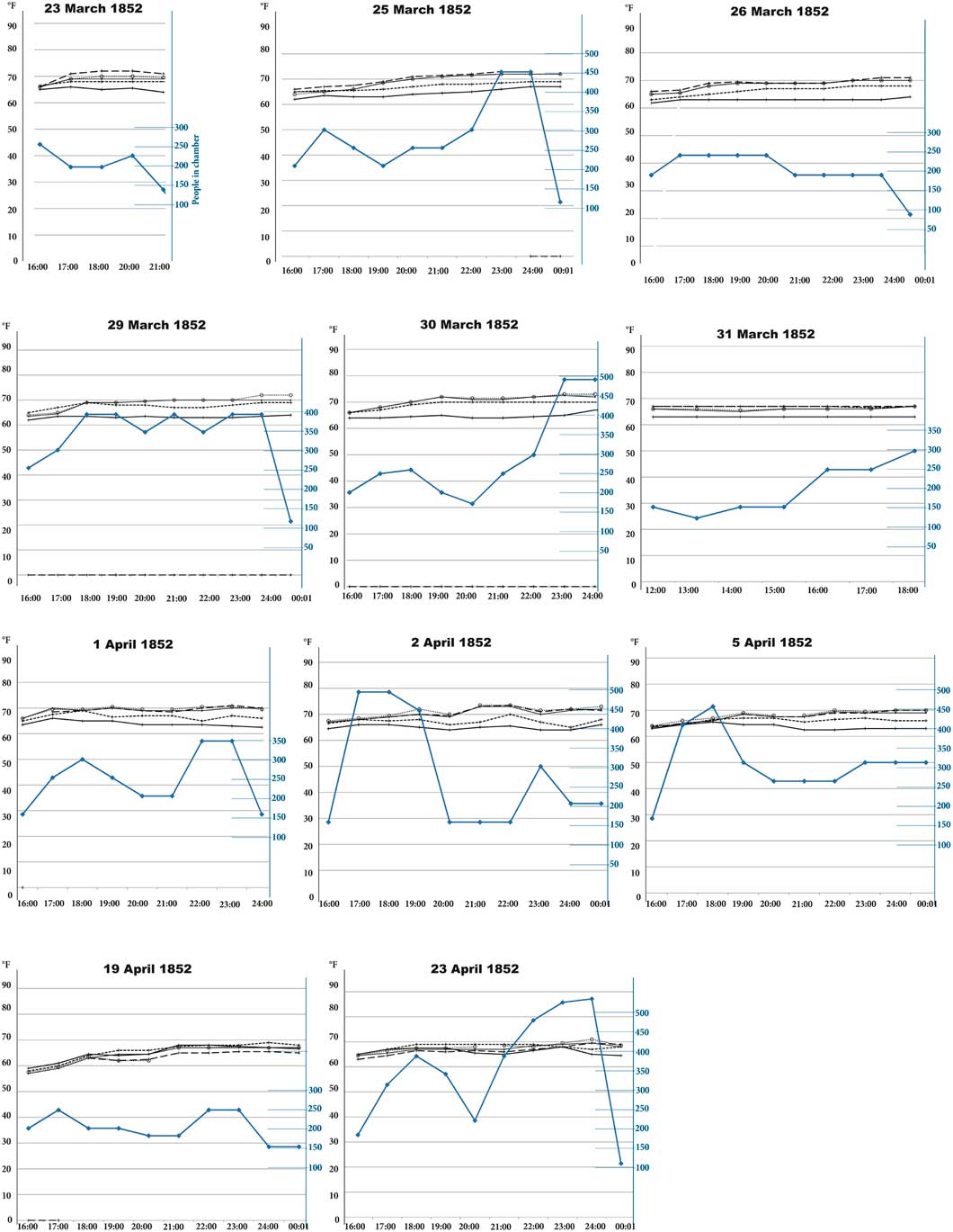
In the light of modern standards, peak temperatures of 73°F (23°C) do not appear exceptionally high. It should be noted that the Victorian MPs wore heavy clothing and preferred lower temperatures.Footnote 159 Records of the set temperature for the permanent House could not be found, but in the temporary House of Commons attendants were required to maintain levels of 60–63°F in winter and prevent temperatures from exceeding 67°F in summer. Gurney referred to 64°F as the ‘most satisfactory temperature’.Footnote 160 To fully understand the level of perceived discomfort, however, it is critical to consider other environmental factors affecting thermal comfort, such radiant temperature, relative humidity or air movement, which were not routinely measured. Humidity was only regularly recorded from December 1853.Footnote 161 The physicians Neil Arnott and John Leslie, who reviewed Reid’s monitoring system, emphasised that the measuring of air temperature was insufficient to gain insights into the thermal sensations MPs were actually experiencing – in particular, the effect of air currents.Footnote 162 As currents remained undetected, MPs felt uncomfortable even when the temperatures were within the recommended range.
THE FIRST INDEPENDENT EXAMINATION
Between March and April 1852, Reid’s system underwent a detailed performance evaluation, coordinated by the Select Committee with the engineers Joseph Locke and Robert Stephenson as technical advisers. Interviews and two independent technical examinations were undertaken to gain a deeper understanding of the climate conditions and MPs’ perceptions. One study was conducted by Gurney, the other by the architect Samuel Whitfield Daukes and the heating engineer Henry Cruger Price. The committee interviewed the Speaker, Sergeant-at-Arms and five MPs on the environmental factors affecting their experience. Thomas Thornton reported that temperatures were unsteady and that strong currents frequently swept over the galleries. In ‘some parts of the evening’, he noted, ‘the temperature is very high, and others comparatively low’.Footnote 163 The Clerk of the House of Commons highlighted a problem with the air being too dry, causing MPs to ‘cough, and considerable irritation in the chest and throat’.Footnote 164 The latter was also observed by the Sergeant-at-Arms and the Speaker, who reported a particularly severe instance on 24 March:
I sent once or twice to Dr. Reid to beg that he would make some change in the state of the air, for it was so dry that it caused an irritation in the throat, and I could hear the Members coughing all around.Footnote 165
The study by Daukes and Price confirmed that the climate was unstable and found that the ventilation rate was often insufficient, at times becoming excessive and resulting in uncomfortable currents. They claimed that it was caused by managerial problems. Daukes observed that cold and hot air entered the House as separate currents, creating an uneven temperature across the floor, and also that currents could suddenly change between hot and cold when valves were switched. Cold and hot air were not sufficiently mixed.Footnote 166 In their final report, Daukes and Price argued that Reid’s control regime was impractical and recommended simplifications such as abandoning the practice of adjusting climates to the ‘continual and conflicting wishes of individual members’.Footnote 167
Gurney came to similar conclusions. In his first report (6 April 1852), he wrote that the simultaneous extraction and supply of air through the floor and ceiling was difficult to co-ordinate.Footnote 168 He further examined this issue, with the assistance of the engineers James Mather, James Hann and John Hutchinson, through tests with differential barometers and anemometers. In his second report (published 13 April 1852), Gurney reported that the ventilation rate was insufficient to counteract overheating,Footnote 169 and that the atmospheric pressure inside the chamber was lower than outdoors, causing air to enter with great force when doors were opened. His diagnosis was that the quantity of vitiated air extracted through the up-cast shaft was not matched by the fan-driven supply. The fans were introduced by Reid with the intention of maintaining the balance artificially. Air was to be blown in with ‘such a force that the air shall have equal pressure within and without’,Footnote 170 but Gurney claimed that the fan and stack were difficult to synchronise effectively. He proposed to adopt a purely stack-driven system in which fresh air was able to enter naturally, responding to the pull induced by the up-cast shaft.Footnote 171 After these enquiries, the Select Committee authorised Reid to implement alterations outlined in his memorandum and overturned Barry’s earlier rejection of the new lighting system.
REID’S SYSTEM GETS ANOTHER TRIAL
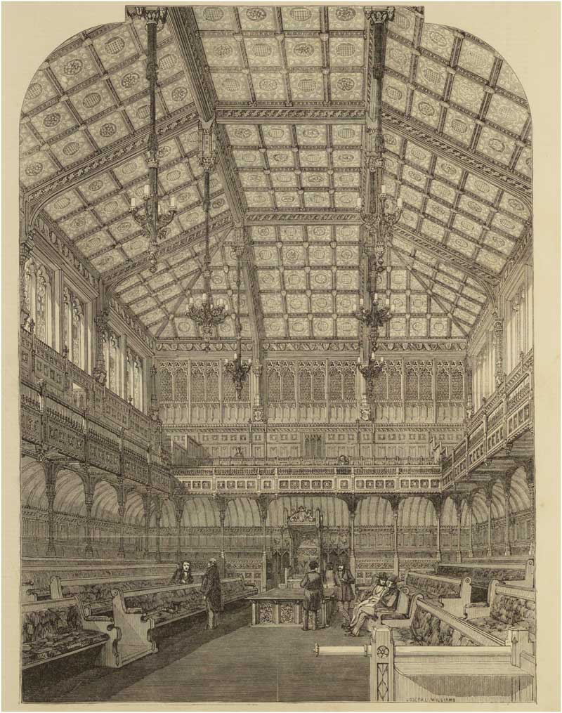
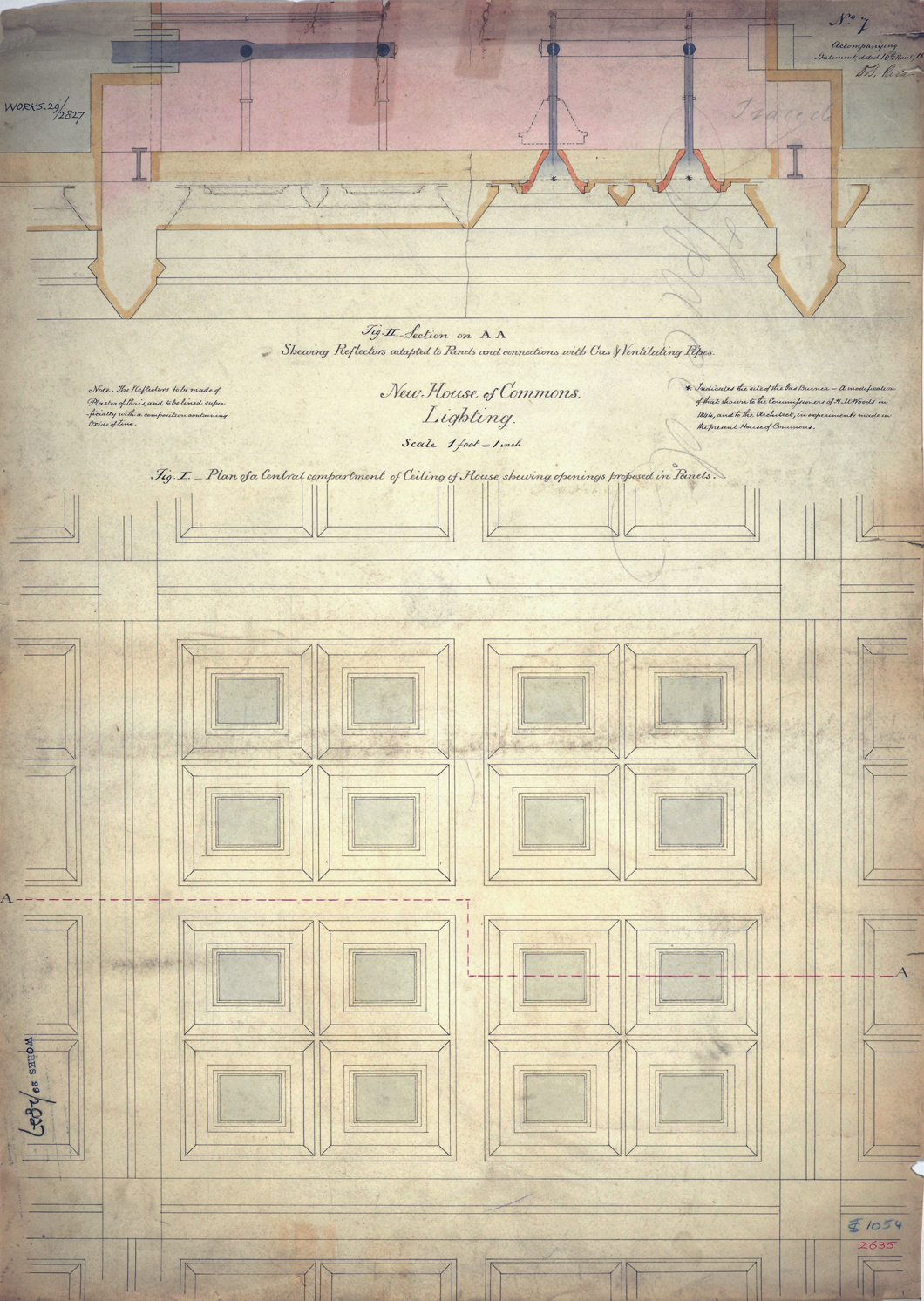
The original lighting, which was designed by Barry and James FaradayFootnote 172 to harmonise with the Gothic detailing, comprised six gas chandeliers hung around the horizontal section of ceiling (fig 23).Footnote 173 It was adopted after Barry had rejected a different lighting system that Reid designed in 1848 to be compatible with the ceiling supply.Footnote 174 Details showing how the lighting was to be integrated into the ceiling were submitted to the Office of Woods on 10 March 1848. Aiming to cast the whole chamber in a soft and uniform light, the entire ceiling was to be covered with 336 small lights (fig 24).Footnote 175 Conical light reflectors were to be inserted into the centre of each ceiling panel,Footnote 176 which also functioned as hoods through which the gas fumes could be extracted upwards. The cones terminated in flues connected to the up-cast shaft. Fresh air was supplied downwards through gaps around the edge of each ceiling panel, while the up-cast shaft ensured that fumes were instantly evacuated before they could contaminate or overheat the supply air.
Interior of the House of Commons with original gas chandeliers designed by Charles Barry and James Faraday, 1852, Illustrated London News, 7 February 1852. Photograph: © Cambridge University Library.
Detail showing Reid’s scheme for integrating the gas lighting system into the panelled ceiling, by Reid, 10 March 1848. PRO: Work 29/2827. Photograph: © National Archives, Kew.
These drawings were forwarded to Barry on 22 March 1848.Footnote 177 He, in several letters to the Office of Woods, opposed Reid’s involvement in the design of lighting and rejected his scheme for interfering with the architecture of the ceiling.Footnote 178 Instead, he advocated the use of self-ventilating gas chandeliers that James Faraday had developed for the House of Lords,Footnote 179 where fresh air was also supplied downwards through the ceiling.Footnote 180 For nine months, the issue was the subject of negotiations, but Barry persuaded the commissioners to adopt Faraday’s system.Footnote 181 Reid wrote several highly emotional letters warning the commissioners that the lighting and ventilation should be designed as an integrated system.Footnote 182
The problems encountered in February 1852 show that these warnings were not unjustified, and Lord Seymour saw them as a manifestation of insufficient co-operation in the design.Footnote 183 Reid argued that it could be resolved by returning to his original plans, but the new lighting installed during the Easter recess of 1852 neither adhered to his original plans, nor facilitated the use of a downward supply through the central panels.Footnote 184 Instead, he reorganised the ceiling system. The fresh air chamber in the centre was converted into a vitiated air chamber and the supply was moved to the sloped side panels. The new vitiated air chamber was connected to the up-cast shaft, and gas lights were installed in sixteen of the sixty-four oak panels.Footnote 185 Prints in Illustrated London News show that it was composed of cone-shaped reflectors below which rings with open gas flames were suspended. Instead of being extracted through separate flues, gas fumes simply rose through the top of the reflectors into the vitiated air chamber.Footnote 186
A first demonstration of the new arrangements was made during the sitting on 19 April.Footnote 187 Reid claimed that the modification reduced the temperature difference between the floor and gallery to 2°F, a claim that the data in the logbooks seem to confirm. The largest recorded difference was 3°F, compared to 11°F (5°C) before the alterations.Footnote 188 Temperatures were also consistently lower and more stable. The average daily temperature inside the gallery had fallen by 2°F and varied by no more than 4°F, compared to 7°F before the recess.
In another letter to the Office of Works (29 June 1852), Reid stressed that the ventilation had further improved after introducing a new steam engine for the fan driving the floor supply,Footnote 189 but he was still concerned with the state of the system. He wrote that important features were ‘executed promptly and in some cases in a merely temporary manner many arrangements that should now be put on a more systematic and permanent footing’. Reid received permission to improve the system in September, but was unable to complete the work before his contract had ended.Footnote 190 When the engineer Alfred Meeson took over his role as superintendent in November, it was still unfinished. Meeson reported that alterations had to be done under pressure of time to ensure that sittings could resume on 4 November 1852, which resulted in work being roughly executed.Footnote 191 Reid was unable to complete his scheme, let alone optimise its performance, during the nine months that he was in charge of superintending day-to-day operations.
THE SYSTEM UNDER A NEW SUPERINTENDENT
Prompted by recommendations of the committee that the ventilation systems inside the palace should be placed under one, rather two, superintendents, Reid’s employment came under review. The ventilation in the House of Lords was supervised by Meeson, who had also worked as Clerk of Works in Barry’s office. In several letters, Barry warned Lord Manners that appointing Reid for this new post was a risk and that he was not prepared to tolerate his interference.Footnote 192 Reid, in return, threatened Manners with legal action.Footnote 193 Manners discussed this issue with the Exchequer (Benjamin Disraeli) and Prime Minister Lord Derby, and consulted the engineers Stephenson and Locke. The engineers agreed that Reid, despite his expertise in the field of ventilation, was unsuitable due to his inability to co-operate with Barry.Footnote 194 Manners terminated his employment in October 1852,Footnote 195 and transferred responsibilities to Meeson.
Meeson undertook a first survey of Reid’s system in January 1853. In a report to the Office of Works, he warned that the system was in poor condition, preventing it from working effectively. The fan and heating of the ceiling supply was in disrepair, and critical features, such as the valves below the floor, were poorly executed or not completed,Footnote 196 causing air to rise through parts of the floor unchecked. Meeson also criticised the control procedures for being too complex, as attendants had to undertake large number of operations in different locations.Footnote 197 Meeson considered such operational aspects the main issue with Reid’s system, highlighting that the temperature was difficult to regulate as the hot-water system could not be adjusted at the required speed to respond to the extreme fluctuation in the number of people. According to the logbooks, the number could change between fifty and 800 people during a single sitting, resulting in sudden changes in the internal heat-load. Temperature control was a major issue. The Speaker reported that Reid had difficulties managing the heat-load during crowded debates,Footnote 198 and the Sergeant-at-Arms observed that the temperature and air quality were highly susceptible to changes in attendance:
MPs suffered from very high temperatures, which Reid was unable to control; frequently, hour after hour, I have requested him, at the desire of the Members and in accordance with my own feelings, to lower the temperature; he appeared to be unable to do so; it sometimes increased rather than diminished during the progress of the evening.Footnote 199
Meeson also reported that Reid’s lighting system had not resolved the overheating problems inside the galleries, and could only be counteracted through higher ventilation rates, which were neither required to maintain a good air quality nor desirable from the point of thermal comfort.
In March 1853 the ‘Standing Committee Report’ of the Standing Committee on the Ventilating and Lighting the House of Commons was commissioned to review Meeson’s recommendations.Footnote 200 It was chaired by the First Commissioner Sir William Molesworth and included Locke and Stephenson as technical consultants. Gurney, who had undertaken lighting experiments inside the temporary House of Commons, was commissioned to develop new lighting.Footnote 201 In his plans, presented to the Office of Works on 10 March,Footnote 202 the lights were moved into the vitiated air chamber above the ceiling and the wooden panels replaced with panes of painted glass.Footnote 203 The fumes from each light were conveyed to the up-cast shaft through separate flues, protecting the firemen and attendants stationed inside the air chamber.Footnote 204 The lights were tested in April 1853, and measurements taken by Gurney’s assistants reveal that the heat-load was phenomenal, causing temperatures in the vitiated air chamber to reach 89°F (31°C) to 123°F (50°C).Footnote 205 Meeson criticised the system, fearing that it could also affect temperatures inside the House.Footnote 206 To dispel such fears, Gurney commissioned the engineers Thomas Mather and James Hann to take measurements within the debating chamber. Thermometers were hung below the glass panels, but no measurable increase could be detected, even when the lights were on for longer periods.Footnote 207 Meeson remained sceptical. In his second report, he claimed that the lights caused the temperature in the galleries to rise to 74°F (23°C).Footnote 208 To address this issue, he reactivated the air supply through the side panels, allowing cool air to be delivered directly into the galleries.Footnote 209 During Meeson’s administration, the ventilation also fell victim to the lack of commitment to Reid’s original principles, but abandoned important features such as the intricate supply and extract arrangements within the floor. Large parts of the perforated floor, intended for the supply and extraction of air, was sealed to protect MPs from rising currents.Footnote 210
THE FINAL ASSESSMENT OF REID’S SYSTEM
After these changes, MPs continued to voice their dissatisfaction during debates between May 1853 and March 1854.Footnote 211 John Bright, MP for Manchester, and Sir Denham Norreys complained about uneven temperatures across the House,Footnote 212 which Richard Spooner, MP for North Warwickshire, described as ‘scolding in one part, and freezing in another’.Footnote 213 There were also issues with dust being carried up by currents rising through the floor. These reportedly caused irritations in the eyes and lungs, making it difficult for MPs to speak without drinking water. Spooner instigated several debates and lobbied for adopting the Gurney’s proposal from 1852. He was opposed by Molesworth, who argued that Meeson needed more time to get the system working optimally, yet after nine months of lobbying Spooner’s initiative would ultimately lead to the decommissioning of Reid’s system.Footnote 214 On 10 March 1853, Spooner made a successful motion for another Select Committee charged with identifying ways of improving the system.Footnote 215
As a member of the committee, Spooner continued to lobby for Gurney’s system. The committee only reviewed Gurney’s earlier proposal and commissioned Gurney to undertake another examination. Two weeks later, he presented a proposal that involved substantial remodelling of Reid’s system.Footnote 216 On 31 March 1854, the Select Committee published a preliminary report advocating Gurney’s scheme.Footnote 217 It claimed that Reid’s system was ‘condemned by common consent’ as unsatisfactory, and recommended testing Gurney’s scheme after the Easter recess. On 6 April, Gurney had a meeting with Molesworth to discuss his proposal and, the following day, submitted his report on the alterations that could be completed over the Easter recess. His system was only to be trialled and, in case it was unsuccessful, they were to revert to Reid’s system.Footnote 218 In two other letters, Gurney stressed that more substantial modifications would be needed to implement his principles fully.Footnote 219 On 10 April, Spooner read the report to the House and moved for the adoption of Gurney’s proposal,Footnote 220 which was approved by vote.Footnote 221 Molesworth criticised the way the process was handled. He felt that Spooner was making the House decide before the committee had undertaken a full inquiry. Its recommendations were based solely on evidence given by Meeson and Gurney.Footnote 222
GURNEY’S RIVAL SYSTEM
The alterations required to test Gurney’s system were made between 14 and 26 April 1853 and its performance was reviewed by the House of Commons’ Select Committee, and another committee appointed to review Barry’s system in the House of Lords. Having received similar levels of disapproval as Reid’s system, the Lords also considered adopting Gurney’s alternative system should trials in the Commons be unsuccessful. MPs were interviewed before and after the alterations to determine how far Gurney’s system had improved thermal comfort.
For the tests, the Clock Tower was converted into the main up-cast shaft, which was used to extract vitiated air through the centre of the main floor and the central ceiling panels. The vitiated air from the floor and ceiling was conveyed to the Clock Tower through the former fresh air passages in the basement. Reid’s original up-cast shaft and roof level inlets were retained, but the floor level supply was re-modelled to allow fresh air to be driven into the House solely through the pull of the two stacks. Instead of introducing air through remote inlets and long passages, which required mechanical assistance, fresh air was admitted directly from the Star Chamber and Commons Courts.Footnote 223
Gurney also replaced Reid’s hot-water apparatus with a steam heating system to allow the temperature to be more rapidly adjusted in response to changes in attendance.Footnote 224 Much care was taken in maintaining a narrower range of temperatures and more optimal humidity.Footnote 225 Attendants were ordered to maintain temperatures between 63°F and 64°F (17°C–18°C).Footnote 226 The internal currents were also monitored using down feathers that were attached to strings suspended across the chamber.Footnote 227 The logbooks did not include measured data for this period, but interviews with MPs between May and July 1854 suggest that the climate had significantly improved. The Sergeant-at-Arms reported that the temperature was more tightly managed, draughts markedly reduced and the atmosphere felt fresh even after long debates.Footnote 228 According to Robert Smith, MP for Northampton, the atmosphere was fresher and did not become oppressively hot.Footnote 229 The MP for North Riding noted that draughts only occurred occasionally,Footnote 230 and Edward Bouverie, MP for Kilmarnock Burghs, found that the attendants were able to adjust the temperature more quickly.Footnote 231 In its second report (26 May 1854), the Select Committee formally announced the end of Reid’s system. It concluded that Gurney’s interventions were successful in improving thermal comfort and recommended that the system be permanently adopted. It wrote that MPs perceived the atmosphere as ‘sensibly sweeter, fresher and purer’ and that the temperature was under tighter control.Footnote 232 The House of Lords was also re-modelled following Gurney’s principles.Footnote 233
CONCLUSION: THE RISE AND FALL OF REID’S LEGACY
This paper has retraced how Reid’s masterplan for the ventilation of the Palace of Westminster evolved, and illuminated the role of empirical observations in addressing fundamental technical and human aspects of environmental design. Focusing on human aspects, these enquiries exemplified how Reid’s medical background influenced his approach to environmental design in a way that was distinctive from the more technical focus of civil engineering of its day. MPs were directly involved in evaluating and refining the environmental systems from a thermal comfort perspective. This included inquiries into environmental monitoring regimes that were responsive not only to physical measurements, but also to the MPs’ perceived comfort or air quality. These culminated in the highly sophisticated system of the permanent House of Commons.
Its design, however, cannot be understood through these scientific inquiries alone, as it was also influenced by the political context. Key features, such as the lighting system or air supply, were the outcome of intense negotiation and Reid’s power struggle with the architect. Over the short period during which Reid was in charge of running the system, he was also unable to complete, let alone optimise, the design and operational procedures. Meeson, who succeeded Reid as superintendent, did not continue his efforts to realise the sophisticated strategy. When Gurney undertook the last test of Reid’s system in 1854, most of the floor, which had been perforated for the supply and extraction of air, had been sealed. It was, therefore, never proven if Reid’s strategy could have worked.
From 1852 to 1854, Reid’s system was subject to continuous scrutiny from scientists, parliamentary committees and individual MPs. Evaluating its performance became a political process, not the least as the MPs were exceptionally powerful occupants who regularly voiced their discontent and demanded measures to improve thermal comfort. Reid, Meeson and Gurney were confronted with the challenge of devising a system that satisfied the MPs. The occupants’ perception, rather than physical measurements, became the ultimate measure by which Reid’s system was evaluated. Several scientific studies were conducted, which, similar to modern building performance evaluations, combined physical measurements and experiments with qualitative interviews that reviewed the occupants’ experience.Footnote 234 Reid anticipated the concept of an intelligent system responsive to feedback gained through measurements and subjective responses from occupants. Historic records, however, suggest that it was too complex to be operated entirely manually without modern computerised controls, electronic sensors or actuators. Attendants had difficulties with collecting and processing large quantities of data at the required speed, and with operating the heating and ventilation. Environmental control was an elaborate manual procedure that relied on the skills and diligence of the attendants.
Reid’s work at the Palace of Westminster features extensively in American and European technical literature, and had a strong influence on the nineteenth-century discourse within the field of heating and ventilation.Footnote 235 Here, however, we have revealed that Reid’s lasting contribution to the ventilation of the palace itself was limited and his legacy short-lived. His responsibility was confined to the House of Commons, accounting only for a small area of the palace. Working with other engineers, Barry developed most of ventilation in the palace. The numerous ventilation shafts on the roof, including the three Gothic turrets above the river front, were added by Barry, whose team retained and incorporated some features of Reid’s work, such as the parts of central air supply served by the Victoria Tower. Although reduced in size and no longer serving as a central outlet, the Central Tower was initially retained as a local shaft for the House of Lords. After 1854, it became redundant when Gurney converted the Victoria Tower into the up-cast shaft instead. Taking a term from evolutionary biology, it could be understood as a vestigial of the palace’s design evolution.
Failing to satisfy the MPs from a thermal comfort perspective, Reid’s system was replaced with a new system. This was in continual use for ninety years, during which it underwent various technical refinements. Although Barry’s system was also re-modelled following Gurney’s approach, his ventilation turrets remained in use. Therefore, it could be argued that Gurney and Barry had a more lasting influence. The fact that only a few features of Reid’s system survived beyond the 1850s might suggest that previous studies overemphasised the level of Reid’s contribution. However, it could also mean that his legacy can only be fully understood if read as a contribution to a system that was continuously evolving, with various features being re-shaped by subsequent generations of scientists and engineers.
ABBREVIATIONS AND BIBLIOGRAPHY
- Commissioners for Completion Commissioners for the Completion of the New Palace of Westminster
Commissioners of Woods Commissioners of Woods and Forests
- HC
House of Commons
- HL
House of Lords
- HLRO
Parliamentary Archives (formerly House of Lords Record Office)
- PED
Parliamentary Estate Directorate
- PRO
The National Archives: Public Record Office


 Open access