


1. Introduction
Modern subduction megathrusts have been extensively investigated during International Ocean Discovery Program (IODP) / Ocean Drilling Program (ODP) expeditions over the last 50 years, with great improvements in the understanding of their architecture, fluid-transport properties and lithological composition (for a review, Saffer & Tobin, Reference Saffer and Tobin2011). However, because of the extremely challenging conditions of drilling in several kilometer-deep oceanic trenches, scientific drilling is limited in depth, and cores offer just one-dimensional insights on the internal architecture of faults. Moreover, the acoustic transparency and the small scale of features within fault zones (meters to tens of meters), well below standard seismic resolution, allow only large scale imaging of the active megathrust faults by means of seismic reflection surveys.
Hence, field-based studies of fossil subduction zones are the only method to investigate the mesoscale architecture of megathrusts. Detailed studies on exhumed subduction-related shear zones provided useful information by documenting that their shallow portion is commonly characterized by heterogeneous composition and architecture (e.g., Vollmer & Bosworth, Reference Vollmer, Bosworth and Raymond1984; Cowan, Reference Cowan1985; Moore & Byrne, Reference Moore and Byrne1987; Meneghini & Moore, Reference Meneghini and Moore2007; Vannucchi, Remitti & Bettelli, Reference Vannucchi, Remitti and Bettelli2008; Fagereng & Sibson, Reference Fagereng and Sibson2010; Festa et al. Reference Festa, Dilek, Pini, Codegone and Ogata2012; Kimura et al. Reference Kimura, Yamaguchi, Hojo, Kitamura, Kameda, Ujiie, Hamada, Hamahashi and Hina2012; Ujiie & Kimura, Reference Ujiie and Kimura2014). In fact, subduction megathrusts commonly incorporate poorly to non-consolidated sediments from the seafloor level and transport them at depth, where tectonic deformation is superimposed on sediment consolidation and diagenesis at increasing pressure and temperature (Maltman, Reference Maltman1994). The resulting heterogeneous rock assemblage (i.e., mélange and broken formation) displays strong internal contrasts in rheology and fluid transport properties, inferred to play a significant role in controlling the complex seismic behavior typical of shallow megathrusts settings (Fagereng & Sibson, Reference Fagereng and Sibson2010; Wei, McGuire & Richardson, Reference Wei, McGuire and Richardson2012).
In this paper, we describe the internal structure of the thrust bounding the base of the Sestola Vidiciatico tectonic Unit (SVU hereafter) in the Northern Apennines (Fig. 1) through multiscale field- and laboratory-based structural studies. The SVU records deformation in a range of temperature and depth comparable to the extent of the shallow portion of active megathrusts (i.e. maximum temperatures of ~150 °C and ~4–5 km burial depth). We discuss then the implications of our observations for the mechanics of the shallowest portion of megathrusts.
Simplified structural sketch (a) and geological section of the surroundings of Vidiciatico (b), modified after (Bettelli & Panini, Reference Bettelli and Panini1992; Plesi et al. Reference Plesi, Daniele, Botti and Palandri2002; Botti et al. Reference Botti, Daniele, Baldacci, Palandri, Ribolini, Ungari and Molli2011). The inset shows the location of the study area, enlarged in Figure 2a.

2. Geological setting
The Northern Apennine mountain chain results from the convergence between the European plate and Adriatic microplate (i.e., African plate), from Late Cretaceous oceanic crust subduction to Cenozoic continental collision and related crustal thickening and uplift (e.g., Boccaletti, Elter & Guazzone, Reference Boccaletti, Elter and Guazzone1971; Coward & Dietrich, Reference Coward, Dietrich, Coward, Dietrich and Park1989; Vai & Martini, Reference Vai and Martini2001 and reference therein). Since Late Cretaceous to early Eocene, the consumption of oceanic crust built up the Ligurian accretionary complex (e.g., Principi & Treves, Reference Principi and Treves1984; Bortolotti, Principi & Treves, Reference Bortolotti, Principi, Treves, Vai and Martini2001; Marroni, Meneghini & Pandolfi, Reference Marroni, Meneghini and Pandolfi2010). The SVU developed during the early-middle Miocene as a regional-scale shear zone, 200 km long and about 200 m thick, between the overthrusting Ligurian paleo-accretionary complex and the underthrusting Tuscan/Umbrian Units of the Adriatic continental margin (e.g. Vannucchi, Remitti & Bettelli, Reference Vannucchi, Remitti and Bettelli2008 and reference therein). The SVU is formed of different tectonically superposed units, which are hundreds of meters to kilometers wide and were derived from the Ligurian accretionary complex (Late Jurassic – middle Eocene) and the slope deposits emplaced at the toe and atop of its frontal part (late Eocene – middle Miocene) (Bettelli & Panini, Reference Bettelli and Panini1992; Remitti, Bettelli & Vannucchi, Reference Remitti, Bettelli and Vannucchi2007; Remitti et al. Reference Remitti, Balestrieri, Vannucchi and Bettelli2013; Lucente & Pini, Reference Lucente and Pini2008). The SVU is bounded and cut by several anastomosing thrust faults (Vannucchi, Remitti & Bettelli, Reference Vannucchi, Remitti and Bettelli2008; Vannucchi et al. Reference Vannucchi, Sage, Phipps Morgan, Remitti and Collot2012).
Although the SVU has been extensively studied at the regional scale (e.g., Remitti, Bettelli & Vannucchi, Reference Remitti, Bettelli and Vannucchi2007; Vannucchi, Remitti & Bettelli, Reference Vannucchi, Remitti and Bettelli2008), here we present the first detailed study of the thrust bounding the base of the SVU, which is characterized by a ramp-flat architecture at regional scale. Vitrinite reflectance, illite crystallinity and apatite fission track data document that the SVU and the footwall rocks reached maximum temperatures around 150 °C, corresponding to ~4-5 km of burial under a geothermal gradient of 30 °C/km (Reutter, Reference Reutter and Wezel1981; Botti, Aldega & Corrado, Reference Botti, Aldega and Corrado2004; Vannucchi, Remitti & Bettelli, Reference Vannucchi, Remitti and Bettelli2008; Thomson et al. Reference Thomson, Brandon, Reiners, Zattin, Isaacson and Balestrieri2010). At the regional scale, the basal thrust is crosscut by middle-late Miocene thrust faults, which segmented the basal thrust delimiting substantially undeformed portions, as the one outcropping in Vidiciatico (Fig. 1; Bettelli, Panini & Capitani, Reference Bettelli, Panini and Capitani2002, Plesi et al. Reference Plesi, Daniele, Botti and Palandri2002; Botti et al. Reference Botti, Daniele, Baldacci, Palandri, Ribolini, Ungari and Molli2011). The deformation structures within the basal thrust can therefore reasonably be attributed to the underthrusting activity of the SVU.
3. Methods
We constructed a geological map of the study area of scale 1:2,000 (Fig. 2a) based on field surveys and the existing geological map (1:10,000; http://geoportale.regione.emilia-romagna.it/it/mappe/informazioni-geoscientifiche/geologia/carta-geologica-1-10.000). The map highlights lithological variations within the SVU, but does not refer to official geological formation names due to the lack of biochronological constraints, which were beyond the aim of this study. The geological map served to address the mesoscale structural analysis of the basal thrust and to constrain sampling finalized to obtain a series of thin sections used for optical and Scanning Electron microscopy.
Geological setting of the basal thrust near Vidiciatico. (a) Interpreted lithological map of the study area. (b) Stereoplot of the orientations of the main fault (black), of the sandstone beds (brown) and of the flattening foliation in the SVU tectonic slices (blue). Equiareal, lower hemisphere projection obtained using the software Stereonet 9 (Allmendinger, Cardozo & Fisher, Reference Allmendinger, Cardozo and Fisher2012).

4. Meso- to microscale structure of the basal thrust
The footwall of the SVU basal thrust consists of a poorly deformed turbiditic sequence, attributed to the Umbrian–Tuscan sequence of Burdigalian age (Botti et al. Reference Botti, Daniele, Baldacci, Palandri, Ribolini, Ungari and Molli2011). Meter-spaced planar shear calcite veins dipping at medium to high angle toward NNE cut the sandstone beds with slight normal offset. The contact between the turbidites and the SVU is marked by a less than 5 m thick fault zone, whose orientation is nearly parallel to the turbidites bedding (Fig. 2b). The SVU in the hanging wall comprises lenticular-shaped tectonic slices of variable origin (Vannucchi, Remitti & Bettelli, Reference Vannucchi, Remitti and Bettelli2008; Vannucchi et al. Reference Vannucchi, Sage, Phipps Morgan, Remitti and Collot2012). In the study area, these include Oligo-Miocene marls (e.g. Marmoreto Marls, Poggialto Formation, Civago Marls), sedimentary breccias of uncertain age (polygenic argillaceous breccias) and slices of varicolored shale and limestone of pre-middle Eocene age (Botti et al. Reference Botti, Daniele, Baldacci, Palandri, Ribolini, Ungari and Molli2011). The contacts between lithological units are in some cases clearly tectonic and bounded by a thrust fault (e.g., the upper contact in Fig. 2a), while in other cases the nature of the contacts is undetermined (simple black lines in Fig. 2a). In the studied outcrops (Fig. 2), the SVU is composed of oblate slices of light gray and dark gray marls, which show a tectonic fabric of centimeter-spaced shear fractures coated by a thin layer of slickensides of iron oxides. The shear fractures have mostly normal shear sense and obliterate the sedimentary bedding. Sporadic competent sandstone or limestone beds are boudinaged, suggesting a component of flattening. The flattening foliation of the oblate slices of marls form an angle of about 30° with the basal thrust (Fig. 2b), suggesting low angle imbrication above it.
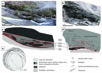
The present day orientation of the basal thrust, dipping about 30° to N320° (Fig. 2b), results from its involvement in post-late Miocene thrusts and folds (Fig. 1), and its original orientation is unknown. The thrust fault zone, composed of rocks with a pervasive fabric defined by imbricated lens-shaped lithons and cut by several calcite shear veins (Fig. 3), is in sharp contact with the footwall turbidites. The transition to the hanging wall SVU is instead gradual, and marked by the decrease in the intensity of fractures and shear veins (Fig. 3a-d). The calcite shear veins are suitable for kinematic analysis because they produce nice calcite slickenfibers and steps, which represent very clear shear sense indicators (Doblas, 1998, Koehn & Passchier, Reference Koehn and Passchier2000). Even dispersed, the slip vectors of the shear veins within the thrust fault zone indicate dominant top to the NNE sense of transport (Fig. 3e). Within the fault zone, we distinguish four structural domains (D1 to D4, Fig. 3) on the basis of their different deformation style at the meso- and microscale.
Internal structure of the basal thrust near Vidiciatico. (a) Photomosaic of one of the outcrops of the basal thrust fault, where the hanging wall consists of light gray marls. The photomosaic was combined using a cylindrical projection, so that the vertical lines are preserved, but there is a distortion of horizontal lines. (b) Photograph of one of the outcrops of the basal thrust fault, where the hanging wall consists in dark gray marls. Due to the prospective distortion, the scale varies in the image. (c and d) Sketches showing the main structural features and the interpreted structural units represented in Figure 3a and b. (e) Stereoplot of the calcite shear veins in the basal thrust shear zone, with the slip vectors inferred from the slickensides. Equiareal, lower hemisphere projection obtained using the software FaultKin7 (Allmendinger, Cardozo & Fisher, Reference Allmendinger, Cardozo and Fisher2012).
4.a. Domain 1 (D1)
Domain 1 represents the basal part of the fault zone and consists of an up to 30 cm thick horizon of laminated dark gray siltstone. The lower contact with the sandstones in the footwall is lined by a thin, discontinuous calcite shear vein. The upper contact with D2 is lined by a 3–5 cm thick shear vein. Internally, D1 is deformed by a pervasive and closely spaced (less than 1 mm) foliation subparallel to the sedimentary lamination and to the shear veins bounding the layer (Fig. 4a).
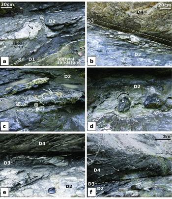
Mesoscale structures of the fault zone. (a) Close up of the contacts between the footwall, D1 and D2, where D2 consists of light gray marls including foliated domains and hard lithons bounded by shear calcite veins. (b) Close up of the contacts between D2, D3 and D4. The latter consists of fractured competent carbonate-rich light gray marls. (c) Detail of the tail of a hard lithon embedded in D2, showing angular breccias cemented by calcite crystals. (d) Detail of rounded hard blocks of sandstone-rich limestone, embedded within foliated marls within D2. The arrow shows the rotation of the block inferred from the deflection of the foliation in the marls. (e) Detail of the internal texture of D3, showing the pervasive foliation and boudinage of inactive calcite shear veins. (f) Details of the outcrop in Figure 3b, showing the deflection of the foliation in D4 due to shear along D3, and its gradual upward decrease. D4 consists of pervasively foliate, clay-rich dark gray marls.
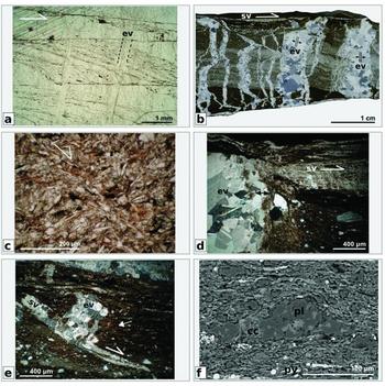
The shear veins have crack-and-seal texture (Ramsay, Reference Ramsay1980) marked by trails of inclusions of the wall rock. Individual increments are oriented at 20 to 40° to the vein walls (Fig. 5a). The siltstone is laminated at the sub-centimeter scale, with alternating coarse and fine, clay-rich laminae (Fig. 5b). The clastic component includes quartz, feldspar, mica and biotite lamellae, illite and calcareous bioclasts, and the cement consists in calcite. The sedimentary lamination is crosscut by deformation bands, shear calcite veins and extensional calcite veins. Deformation bands are spaced apart about 10–20 mm and form an angle of about 30°–40° to the general orientation of the thrust fault. They are characterized by the reorientation of mineral grains without fracturing. The alignment of mica lamellae to the shear bands and their asymmetry within the bounded volume (Fig. 5c) indicate a dextral component of movement, synthetic with the main transport direction of the thrust. Thin (< 1 mm), discontinuous shear calcite veins are found parallel to the sedimentary lamination and locally infill the shear bands. The vein calcite is opaque and contains small inclusions of sediment particles (Fig. 5d). Shear veins are crosscut by extensional veins oriented at 80–90° to the sedimentary lamination, up to 8–10 mm thick (Fig. 5b, d). The extensional veins perpendicular to the lamination have irregular, wavy interfaces to the wall rock and include crack-and-seal increments traced by wall rock inclusions (Fig. 5d, e). The thinnest veins have anastomosing geometry, with several branches enclosing host rock lamellae (Fig. 5b). The crosscutting relations between different extensional veins and branches are not clear, as the blocky calcite crystals are continuous across the intersections between adjacent veins. The draping of dark dissolution seams around veins, which acted as “hard” indenters, suggests that the siltstone-claystone underwent layer perpendicular compaction after the emplacement of extensional veins (Fig. 5d, e). In the siltstone, phyllosilicate lamellae are preferentially oriented defining a microscale layer-parallel foliation and are draped around hard quartz and feldspar clasts. Quartz and feldspar clasts are strongly corroded, and calcite precipitated in microcracks and pressure shadows (Fig. 5f). These features altogether suggest that part of the wavy and anastomosing geometry of the calcite extensional veins can be due to the general compaction of the layer, likely due to pressure-solution processes. The blocky and elongate-blocky calcite crystals in both extensional and shear veins often show closely spaced, straight and thin Type I twins (Burkhard, Reference Burkhard1993).
Microstructures of D1. (a) Crack-and-seal calcite shear vein bounding the top of D1. The crack-and-seal increments are cut at high angle by two extensional veins. Plane polarized micrograph. (b) Overview of anastomosing extensional veins (ev) perpendicular to the layer. Indentation of the layer-perpendicular veins against a layer-parallel, discontinuous shear vein (sv) suggest layer-perpendicular compaction. Cross polarized thin section scan. (c) Shear band within the siltstone, showing rearrangement of grains without fracturing. Plane polarized micrograph. (d) Internally turbid shear vein, crosscuts by a perpendicular extensional vein with crack-and-seal microstructure traced by wall rock inclusion trails (arrows). Cross polarized micrograph. (e) Crack-and-seal extensional vein (ev) associated with a partially dissolved shear vein (sv), acting as hard object during general layer-perpendicular shortening. The dark dissolution seams in the siltstone are draped around the veins, and are almost absent in the shaded area on the right of the vein (arrow). Cross polarized micrograph. (f) Internal texture of the siltstone, showing evidence of pressure-solution related flattening and deposition of calcite (cc) in pressure shadows, represented by microcracks in a plagioclase (pl) clast, and smearing of pyrite (py) parallel to the dissolution seams. Back Scattered Electron image.
4.b. Domain 2 (D2)
The second domain (D2) is 50–80 cm thick and includes strongly deformed marls with variable clay, carbonate and silt contents. The marls show a penetrative fabric consisting of rhombohedral lithons, whose long axis is oriented at low angle of ~20° to the above Domain 3 (D3; see below). The bounding surfaces of the lithons are polished and slickensided, with local millimeter-scale calcite fibers, suggesting that they acted as slip surfaces. Lithons become thinner and flatter with the increase of clay content, forming flattening surfaces which define a mesoscale foliation, often draped and deflected around decimeter-scale competent lithons (Fig. 4b, d). In clay-dominated domains, centimeters-scale diffuse synthetic shear bands form a typical S-C’ fabric, deflected around hard carbonatic clasts. At the meter scale, the marls are cut by several sharp calcite-filled shear veins, parallel or at low angle of about 20° to D3, synthetic with the top to the NE sense of transport in D3 (Fig. 3e). In dilational sites at necks and tails of hard, carbonate-rich lithons, the calcite shear veins include calcite-cemented breccias of angular clasts of the wall rock (Fig. 4c). Calcite shear veins are more abundant and continuous in competent carbonate-rich domains (Fig. 3).
At the microscale, the inner part of the marls lithons is substantially undeformed and preserves sedimentary structures like bioturbation or calcareous bioclasts (Fig. 6a, b). The surfaces bounding the lithons are lined by curvilinear and weakly anastomosing dark dissolution seams, with non-sutured surfaces typical of relatively phyllosilicate-rich lithologies (Logan & Semeniuk, Reference Logan and Semeniuk1976) (Fig. 6a). The dark seams bounding the lithons are enriched in phyllosilicates and slightly sheared, as suggested also by the preferred orientation of the clay lamellae (sm in Fig. 6c). Several calcite shear and extensional veins are localized around lithons (Fig. 6a-d). Shear veins are filled by elongated blocky calcite crystals subparallel to the vein walls. The interfaces between shear veins and the foliated domains are lobate and often lined by dark dissolution seams, which are also found in the sheared, clay-enriched domains (Fig. 6d). Extensional veins have anastomosing trends subparallel to the dissolution seams bounding the lithons and are sealed by fibrous calcite crystals perpendicular to the vein boundaries (Fig. 6a-c). The extensional veins crosscut the shear veins.
Microstructures of D2. (a) Overview of the deformation style of a marl lithon. The internally not deformed lithon is bounded by two surfaces (hatched white lines) lined by several veins and dark dissolution seams. Both shear veins (sv) and extensional veins (ev) are emplaced along the lithon boundaries. Cross polarized thin section scan. (b) Detail of the inner part of a marl lithon, bounded by an extensional vein (ev) preserving bioturbation structures and bioclasts (white arrows). Cross polarized micrograph. (c) Detail of one of the boundaries of the lithon in (a), showing slightly deformed marls (m), a layer of phyllosilicate-rich sheared marls (sm), a shear vein with calcite fibers tangential to vein walls and an extensional anastomosing vein with calcite fibers nearly perpendicular to vein walls. Cross polarized micrograph. (d) Detail of a lithon boundary, lined by a calcite shear vein (sv) and sheared marls. A pressure-solution seam (ps) is visible within the sheared marls. (e and f) Overview of the deformation style within the clay-rich domains. The deformation structures are traced in (f), where light pink is calcite, light gray are more competent layers or clasts, thick black lines are shear bands and thin black lines the foliation traces. Thin section scan, cross polarized nicols. (g) Deformation structures within clay-rich domains, showing the isoorientation of clay lamellae and of elongated clasts (ec), synthetic shear bands cutting more competent domains and a partially dissolved calcite shear vein (sv). Plane polarized micrograph. (h) Mutually crosscutting layer-parallel and layer-perpendicular, folded, calcite extensional veins (ev) in a clay-rich domain. Cross polarized micrograph.
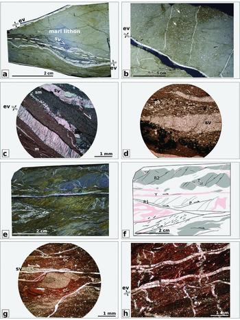
In clay rich domains, the preferred orientation of phyllosilicate lamellae forms a penetrative foliation, displaced by an array of Y, R1, R2, T and P shear bands (sensu Logan et al. Reference Logan, Dengo, Higgs, Wang, Evans and Wong1992), locally lined by thin calcite shear veins (Fig. 6e, f). Fracturing and boudinage affect more competent layers (clastic layers or carbonate-rich layers), clasts or early stage calcite veins (Fig. 6e-g). The penetrative foliation of the clay matrix is crosscut by several generations of thin extensional veins, oriented at high angle to the fault zone, or with anastomosing trajectories often subparallel to the foliation planes. The anastomosing, fault parallel extensional veins are sealed by fibrous calcite crystal perpendicular to the vein walls, and crosscut the phyllosilicate foliation and the shear veins. The fault-perpendicular extensional veins are folded and partially dissolved, suggesting fault-perpendicular compaction of the embedding matrix (Fig. 6h). Fault perpendicular and fault parallel extensional veins have mutually crosscutting relations (Fig. 6h).
4.c. Domain 3 (D3)
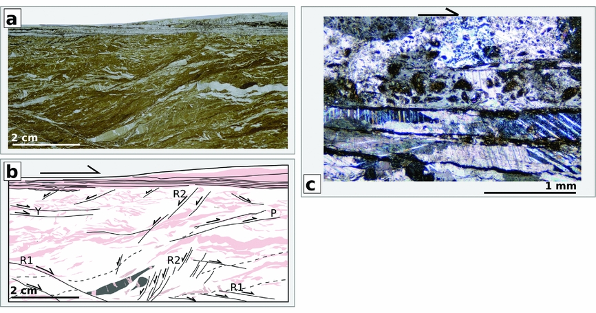
Domain 3 consists of a 20–30 cm thick continuous tabular shear zone separating D2 from D4 and marked at the top by a relatively thick (2-3 cm) calcite shear vein (Fig. 3). Adjacent to the main shear vein, D3 shows a structural fabric similar to D2 clay-rich domains, but with a higher degree of deformation, as shown by the closely spaced foliation which involves also deformed fragments of calcite veins (Fig. 4b, e) and, at the microscale, by the pervasiveness of several generation of calcite shear and extensional veins, which are folded, boudinaged and reoriented (Fig. 7a, b). The calcite crystals in deformed shear veins within clay-rich domains are intensely twinned. At the microscale, the secondary shear bands adjacent to the principal shear veins are both synthetic and antithetic to the shear sense of the main shear vein as inferred from calcite slickenfibers (Fig. 7a, b), and altogether suggest flattening of the sediments perpendicular to the fault plane. The upper boundary vein consists of multiple parallel shear veins separated by thin layers of clay or carbonaceous material. These vein strands are locally cut by breccias of angular clasts of the wall rock and cemented by elongated-blocky calcite crystals with closely spaced, straight Type I twins (Burkhard, Reference Burkhard1993) (Fig. 7c).
Microstructure of D3. (a) The vein bounding the top of D3 and the strongly deformed clay-rich domain immediately below it. Plane polarized thin section scan. (b) Drawing of (a) highlighting the deformation structures: light pink are calcite veins, light gray are competent layers and clasts, thick black lines are shear bands and hatched black lines the foliation traces. (c) Detail of the calcite veins lining the upper boundary of D3, where they are cut by a calcite-cemented breccia of angular clasts of the wall rock. Cross polarized micrograph.
4.d. Domain 4 (D4)
Above D3, a 3 m thick damage zone marks the transition to the hanging wall, which consists in either more calcareous light gray (Fig. 3a) or less calcareous dark gray marls (Fig. 3b). Light gray marls in the hanging wall are rather competent and cut by shear fractures, spaced some centimeters to some decimeters apart, which define elongate rhombohedra with flattening plane oriented at about 40° from D3 (Fig. 4b, e). Dark gray marls are instead cut by a pervasive foliation defined by sub-centimetric flattened lithons. The penetrative tectonic fabric in dark gray marls is deflected in a way consistent with shearing along D3 and is cut by thin synthetic shear veins either parallel or at a low angle of 30° to D3 (Figs 3, 4f).
5. Discussion
5.a. Faulting mechanisms at increasing depth
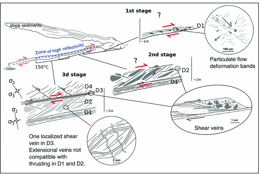
The basal thrust fault zone includes slices of different lithologies that underwent shear strain during thrust faulting at increasing pressure and temperature up to 150 °C (Botti, Aldega & Corrado, Reference Botti, Aldega and Corrado2004). Based on the meso- and microscale deformation structures described above, we suggest a three-stage evolution of the fault zone (Fig. 8).
Sketch showing the spatial and temporal evolution of the studied fault zone and comparison with an active megathrust setting, based on Ranero et al. (Reference Ranero, Grevemeyer, Sahling, Barckhausen, Hensen, Wallmann, Weinrebe, Vannucchi, von Huene and McIntosh2008). The zone of high fluid pressure is shown as estimated on the basis of high amplitude seismic reflectivity along megathrusts. The three phases of deformation of the studied fault zone at the base of the SVU are transitional and partly overlapped, and represent different faulting stages as occurred with increasing depth.
5.a.1. First stage
The first stage is recorded only in D1 siltstone, where shear bands show inter-particle rearrangement without fracturing or internal deformation of the grains (Fig. 5c). Sliding of grains without deformation of the particles themselves is typical of independent particulate flow (Borradaile, Reference Borradaile1981; Knipe, Reference Knipe and Moore1986), enhanced by low effective mean stresses (low confining pressure and/or high fluid pressure), compatible with fluid-rich porous sediments embedded in the thrust fault at shallow depth. Locally, the shear bands are infilled by thin, discontinuous shear veins having internal dirty appearance, suggesting that they developed in not completely lithified sediments (Maltman, Reference Maltman1994). This indicates a gradual transition to dilatant brittle deformation with the increasing grade of cementation of the siltstone, at very shallow depth and temperatures typical of carbonate diagenesis. Similar calcite veins that formed at early diagenetic conditions have been documented in shallow subduction settings, such as the Palaeogene accretionary complex of the central European Alps (Dielforder et al. Reference Dielforder, Vollstaedt, Vennemann, Berger and Herwegh2015; Dielforder, Berger & Herwegh, Reference Dielforder, Berger and Herwegh2016) and in the Apennines (Labaume, Berty & Laurent, Reference Labaume, Berty and Laurent1991).
5.a.2. Second stage
Diagenesis and embrittlement of the sediments lead to a second stage of deformation, where shear strain is attained in a heterogeneous shear zone, at least 1 m thick, involving mainly marls, and minor clay-rich or siltstone domains (D2). The deformation is partly brittle, localized along multiple fault strands lined by shear veins (Fig. 3a, c), and partly accommodated by distributed deformation structures such as pressure-solution seams (Fig. 6d) and diffuse shearing of clay-rich domains (Fig. 6c, e, f).
The deformation style in D2 depends on lithology. In marls, shear veins and pressure solution seams are localized along the anastomosing surfaces bounding competent lithons, which are not deformed internally (Fig. 6a, b). The lack of intergranular deformation in marls suggests that they were already cemented when embedded within the SVU, unlike the D1 siltstone. Shearing, fluid flow and fluid-rock interactions in marls are likely driven by fracturing, which occurred at a very early stage as documented in other portions of the SVU exhumed from shallower settings (Remitti, Bettelli & Vannucchi, Reference Remitti, Bettelli and Vannucchi2007; Remitti et al. Reference Remitti, Bettelli, Panini, Carlini and Vannucchi2012). The size of lithons in marls varies from few millimeters to some decimeters (Figs 3, 4), being larger in competent, carbonate-rich domains. Where large lithons prevail, deformation is localized along meter-scale synthetic shear veins (Fig. 3a, c), with local dilational breccias of angular fragments of the wall rock (Fig. 4c) developed at the edges of competent lithons. Where small, thin lithons prevail, deformation is diffuse without macroscopic shear veins (Fig. 4d. f), and the deformation style is macroscopically ductile. Clay-rich domains can be sedimentary, or, in marls, produced by passive enrichment in insoluble clay minerals, during the development of pressure-solution seams (Fig. 6c, d). In both cases, clay-rich domains show a microscale tectonic fabric characterized by the preferred orientation of clay lamellae displaced by shear bands. This fabric is typical of phyllosilicate-rich gouges deformed by frictional sliding (e.g., Logan et al. Reference Logan, Dengo, Higgs, Wang, Evans and Wong1992; Haines et al. Reference Haines, van der Pluijm, Ikari, Saffer and Marone2009). Episodic dilatancy and embrittlement in clay-rich domains are registered by the emplacement of calcite shear veins (Fig. 6e, f). The frictional strength of foliated clay-rich rocks with interconnected layers of phyllosilicates is lower than their non-oriented equivalent (Collettini et al. Reference Collettini, Niemeijer, Viti and Marone2009; Tesei et al. Reference Tesei, Collettini, Carpenter, Viti and Marone2012; Tesei, Lacroix & Collettini, Reference Tesei, Lacroix and Collettini2015), with friction coefficient at the order of 0.2-0.4, i.e. significantly lower than commonly inferred friction coefficients of 0.6 to 0.85 (Byerlee, Reference Byerlee1978). Clay-rich domains are thus weak compared with calcareous competent lithons, and tend to accommodate strain at low differential stress, although they are only locally present within D2. The very thin shear veins developed in clay-rich domains (e.g., Fig. 6e, f) suggest that they episodically underwent dilatancy and embrittlement.
During the second stage, D1 likely experienced only limited shear strain. Shear veins in D1 are crosscut by extensional veins perpendicular to the layer (Fig. 5b). Grain-scale pressure-solution structures such as calcite precipitation in microcracks and in pressure shadows (Fig. 5f) are pervasive in D1 siltstone, producing an alignment of elongated phyllosilicate minerals parallel to the layer. The alignment of pressure-solution seams and the development of extensional veins perpendicular to the layer are coherent with layer parallel flattening, suggesting that, during this second stage of deformation, shear strain was progressively localized in the above D2, producing a strain decoupling across the shear vein separating D1 from D2.
5.a.3. Third stage
An up to 30 cm thick shear zone (D3), which represents the last stage of deformation at the maximum depth and temperature reached by the thrust (Fig. 8), truncates the brittle and ductile deformation structures in D2. Deformation in D3 is partitioned between a sharp shear vein and a layer of strongly foliated, veined and locally clay-rich marls. The deformation style in D3 is similar to what is described in D2, a combination of shear veins with frictional sliding in clay-rich domains and pressure-solution, but deformation is extremely pervasive due to the strong localization of shear strain in a relatively thin domain (Fig. 7a, b). D4 represents the hanging wall damage zone, and displays deformation structures compatible with shearing along D3, i.e., in light gray marls, synthetic shears (Fig. 3a, c) and, in dark gray marls, a foliation at 30–40° to D3 crosscut by synthetic shears (Fig. 3b, d).
In D2, late deformation structures consist of extensional veins, either perpendicular, or, most frequently, having anastomosing trends roughly parallel to the thrust. Extensional veins in D2 have fibrous structure typical of mode I extensional veins (e.g. Bons, Elburg & Gomez-Rivas, Reference Bons, Elburg and Gomez-Rivas2012), and a dilatant character whatever their orientation. Such characteristics suggest extension nearly independent on the orientation, thus reflecting local, transient conditions of low differential stress and high fluid pressure. Thus, episodically, the state of stress in D1 and D2 (fault parallel shortening or dilation) was incompatible with shearing along D3.
After the first stage of soft sediment deformation recorded in D1, brittle faulting in the basal thrust was always associated with shear veins, as also observed in other exhumed thrusts and megathrusts (e.g., Fisher et al. Reference Fisher, Brantley, Everett and Wambold1995; Fagereng, Remitti & Sibson, Reference Fagereng, Remitti and Sibson2011; Yamaguchi et al. Reference Yamaguchi, Cox, Kimura and Okamoto2011, Reference Yamaguchi, Ujiie, Nakai and Kimura2012). Shear veins have crack-and-seal texture resulting from multiple episodes of cracking, fluid pressure drop and mineral precipitation (Ramsay, Reference Ramsay1980, Labaume, Berty & Laurent, Reference Labaume, Berty and Laurent1991). The widespread occurrence of shear veins, the lack of wear products like cataclasites or gouge in the fault zone and the formation of extensional veins nearly parallel to the fault are coherent with failure at low differential stress and high fluid pressure (e.g., Cox, Reference Cox2010).
5.b. Comparison with active shallow megathrusts
The basal thrust fault in Vidiciatico is one of the several anastomosing thrust faults which accommodated shearing within the 200 m thick SVU shear zone (Remitti, Bettelli & Vannucchi, Reference Remitti, Bettelli and Vannucchi2007; Vannucchi, Remitti & Bettelli, Reference Vannucchi, Remitti and Bettelli2008). Its cumulative thickness of about 4–5 m is similar to what is measured for single fault strands within active megathrust plate boundary faults (Rowe, Moore & Remitti, Reference Rowe, Moore and Remitti2013). In the latest stages of activity at the maximum depth and estimated temperature of about 150 °C, the thickness of the actively deforming fault is reduced to the 20–30 cm of D3. Localization to a thin slipping zone is generally associated with seismic slip (e.g., Sibson, Reference Sibson2003), and the observed thinning of the active shear zone might be related with the progressive transition to the seismogenic, locked zone of active megathrusts at similar temperature (e.g., Oleskewich, Hyndman & Wang, 1999). Alternatively, the planar, continuous D3 shear zone might result from the by-pass of a geometric irregularity (such as a ramp, not outcropping) that caused the deformation of the whole D2 thickness and, generally, the imbrication of tectonic slices in the first hundred meters above the basal thrust mapped in the study area (Fig. 2a). A reduction of fault waviness and of the perturbing effects of geometric heterogeneities is generally associated with increasing displacement accumulated by the fault, and, in the case of the basal thrust, increasing maturity (e.g., Sagy, Brodsky & Axen, Reference Sagy, Brodsky and Axen2007).
The localization of the deformation to D3 is associated with the deactivation of the structural domains below it, where the shear component of strain is overprinted by thrust-parallel flattening, more evident in D1 and recognizable also in D2, where fault perpendicular extensional veins are folded and shortened. Similar strain decoupling across actively shearing décollements has been measured in magnetic susceptibility studies in cores from the basal décollement of active megathrusts, as the one of the Barbados accretionary prism (Housen et al. Reference Housen, Tobin, Labaume, Leitch and Maltman1996) and of the Japan Trench prism (Yang et al. Reference Yang, Mishima, Ujiie, Chester, Mori, Eguchi and Toczko2013). Strain decoupling, likely responding to stress decoupling, suggests that the basal thrust of the SVU was weak.
The mode of brittle failure in the basal thrust of the SVU, characterized by crack-and-seal shear veins since early, shallow stages of activity, is coherent with several qualitative geophysical (high amplitude seismic reflectivity, e.g., Ranero et al. Reference Ranero, Grevemeyer, Sahling, Barckhausen, Hensen, Wallmann, Weinrebe, Vannucchi, von Huene and McIntosh2008; anomalously low P-wave velocity, e.g., Park et al. Reference Park, Fujie, Wijerathne, Hori, Kodaira, Fukao, Moore, Bangs, Kuramoto and Taira2010; high P-to S-wave velocity ratios, Moreno et al. 2014) and geological observations (e.g., Byrne & Fisher, Reference Byrne and Fisher1990; Labaume et al. Reference Labaume, Kastner, Trave, Henry, Shipley, Ogawa, Blum and Bahr1997) that suggest higher than hydrostatic fluid pressure in the shallowest portion of active megathrusts. Episodic locally higher than lithostatic fluid pressures in the thrust zone is also suggested by the emplacement of thrust-parallel, anastomosing extensional veins. As suggested in deepest fossil exhumed subduction complexes (Fisher et al. Reference Fisher, Brantley, Everett and Wambold1995; Fagereng, Remitti & Sibson, Reference Fagereng, Remitti and Sibson2011) and in other fluid-dominated geological settings (Renard et al. 2005), the fault-fracture meshes in the basal thrust of Vidiciatico likely result from multiple, repeated failures accommodating very low displacements. As suggested for deeper settings (Fagereng, Remitti & Sibson, Reference Fagereng, Remitti and Sibson2011), such intermittent failure style might be related with the very low frequency earthquakes recently discovered also in the shallowest portion of several active megathrusts (Obara & Ito, Reference Obara and Ito2005; Nakamura & Sunagawa, Reference Nakamura and Sunagawa2015), at depths similar to those estimated for the activity of basal thrust of the SVU.
6. Conclusions
We described in detail the internal architecture and deformation mechanisms of the thrust bounding the base of the SVU, a regional-scale shear zone sandwiched between the overlying Late Cretaceous – Early Eocene Ligurian accretionary complex, and the underlying Tuscan – Umbrian Units of the Adriatic continental margin, and active from the seafloor down to depths experiencing temperatures of about 150 °C. Because the basal thrust incorporated sediments shortly after their deposition, and transported them down to depths typical of the onset of seismicity in active megathrusts, it represents a good analog for investigating the deformation processes of shallow present day megathrusts above the transition to the seismogenic zone.
Our observations suggest that:
-
(i) The thrust fault zone has maximum thickness of 4–5 m, similar to present day megathrust fault strands, and, with increasing maturity and depth, the active portion of the fault further localizes in a thinner fault zone, less than 30 cm thick. The increasing localization of slip with increasing depth is coherent with conditions approaching those estimated for the transition to the seismogenic zone in active megathrusts.
-
(ii) Early stage diffuse deformation in the sediments within the fault zone is accommodated by soft sediment particulate flow in siltstone domains, and lately by frictional sliding in clay-rich domains, while pressure solution occurs in all lithologies.
-
(iii) Brittle faults are always associated with calcite-filled veins and extensional ones are often unfavorably oriented relative to the stress field required for thrusting, suggesting that faulting was promoted by repeated failures at low effective stresses and in presence of fluids in all stages of activity of the thrust, from shallow settings down to the depth of transition to the seismogenic zone.
-
(iv) The basal thrust fault was active under low differential stress, and the state of stress within the active fault was likely decoupled from that in the footwall, suggesting that the components of the basal thrust fault were weak compared with the footwall.
Acknowledgements
Funding from PRIN 2010/2011 prot. 2010AZR98L_009 to F.R and S.M is gratefully acknowledged. The Authors thank Giuseppe Bettelli for fruitful discussions and for sharing his deep knowledge of the geology of the area. We acknowledge Asuka Yamaguchi and an anonymous reviewer for their careful and constructive comments which strongly improved the manuscript.



