

1. INTRODUCTION
The main purposes of redundant sensors are to provide highly reliable and accurate sensor data and to reconfigure sensor network systems when other sensors fail. These create the fundamentals for the design of fault-tolerant navigation systems and the achievement of reliability and integrity in Inertial Navigation Systems (INS). Overall navigation improvement is to be expected as there is more input information. Through increased redundancy we can obtain noise reduction in the navigation output parameters.
The advantages of using multiple sensors over a single sensor to improve the accuracy of acquired information about an object have been recognized and employed by many engineering disciplines ranging from applications such as a medical decision-making aid system to a combined navigation system (Lam et al., Reference Lam, Wilson, Contillo and Buck2004). Weis and Allan (Reference Weis and Allan1992) presented a high-accuracy clock with a monthly error of one second, by combining three inexpensive wrist watches with monthly errors of 40 seconds. Actually, this technology used heterogeneous sensor data fusion to improve the accuracy. Recently, some researchers have begun to use a similar idea to improve the accuracy of sensors. Bayard combined four inexpensive gyroscopes to form a virtual sensor with higher accuracy output, and called this technology a ‘virtual gyroscope’ (Bayard and Ploen, Reference Bayard and Ploen2003). In the virtual gyroscope the random noise of the gyroscope was estimated by using the Kalman filtering for further compensation, thus its accuracy was improved.
The correlation between the sensors was used to establish the covariance matrix of the system random noise for filtering computation and better accuracy improvements. Lam proposed a very interesting concept to enhance the accuracy of sensors via dynamic random noise characterization and calibration (Lam et al., Reference Lam, Hunt, Sanneman and Underwood2003a; Reference Lam, Stamatakos, Woodruff and Ashton2003b; Reference Lam, Wilson, Contillo and Buck2004).
Redundancy is determined on the basis of hypothesis testing for error detection and isolation. With redundant inertial measurements we can increase reliability aspects at the Inertial Measurement Unit (IMU) and detect defective sensors and unreal signals.
The use of redundant IMUs for navigation purposes is not new. From the very early days of inertial technology, the inertial navigation community was aware of the need and benefits of redundant information. However, the focus of the research and development efforts was Fault Detection and Isolation (FDI). In the early days, the idea was to make use of the redundancy in order to support fault-safe systems. A fault-tolerant system is able not only to detect a defective sensor, but also to isolate it. After isolating a defective sensor, the system may keep working as a fault-tolerant or a fault-safe system depending on the number of remaining sensors. By means of voting schemes (Pejsa, Reference Pejsa1973), it can be shown that a minimum of four sensors are needed to devise a fault-safe system and a minimum of five to devise a fault-isolation one. Sensor configuration for optimal state estimation and optimal FDI was also a topic of research in the early works.
In Sturza (Reference Sturza1988a; Reference Sturza1988b) a comprehensive analysis of the optimal spatial configuration of sensors for FDI applications is provided together with FDI algorithms. In addition, the performance for fail-isolation systems in cases where a sensor is removed due to failure is explored. More recent results on the use of redundant inertial sensors for FDI can be found in (Lennartsson and Skoogh, Reference Lennartsson and Skoogh2003) and (Sukkarieh et al., Reference Sukkarieh, Gibbens, Grocholsky, Willis and Durrant Whyte2000). The former is mainly concerned with the use of skewed redundant configurations for unmanned air vehicles while the latter focuses on guidance, navigation and control of underwater vehicles. The two references are good examples of the wide range of applications for skewed redundant configurations that are currently under research.
Measurement information provided by various navigation sensor systems can be independent, redundant, complementary or cooperative. For example, gyroscope set and accelerometer set, each individually providing independent measurements, are integrated in an IMU to provide complementary and cooperative data that are used to derive the navigation states.
2. OPTIMAL CONFIGURATION OF INERTIAL REDUNDANT SENSOR SYSTEM
Redundancy can be provided by installing a few independent, identical copies of a system and comparing their outputs. INSs are often used in threes, and a computer correlates their outputs. If two of the three consistently differ from the third, the third is considered to have failed and its data is ignored. Deciding between two might be possible if other data from separate sensors are available.
Redundant systems are expensive; the cost of providing backup systems must include the cost of carrying their extra weight. Rather than installing three copies of a system, redundancy can be provided at the component level.
Particular system designs include one in which a fourth single-axis sensor is mounted with its sensitive axis skewed to the three basic sensor axes. This sensor can then act as a check on the basic three and can provide information if one of them should be determined to have failed.
2.1. Criteria for Optimal SRIMU Configurations
In a ‘Sensors Redundant IMU’ (SRIMU) configuration, the orientation of each sensor axis is defined by its azimuth and elevation angles with respect to an orthogonal reference frame, such as the body frame.
Let each axis of the instrument frame be presented by a unit vector Si along the sensing direction of sensor i , the unit vector can be defined in the orthogonal reference frame by:
 $${\rm S}^{\rm i} = {\rm cos}({\rm El}^{\rm i} ){\rm cos}({\rm Az}^{\rm i} )\cdot{\bf i} + {\rm cos}({\rm El}^{\rm i} ){\rm sin}({\rm Az}^{\rm i} )\cdot{\bf j} + {\rm sin}({\rm El}^{\rm i} )\cdot{\bf k}$$
where:
Bold symbols i, j and k are three unit vectors along the corresponding axes of the reference frame (xb, yb, zb).
Superscript i denotes a sensor and its sensing axis.
Eli and Azi are the elevation and azimuth angles of the instrument axis i with respect to the reference frame.
If we suppose that a SRIMU system encloses n sensors, identified by 1, 2, 3… n, the measurement equations of the SRIMU system can be formulated as follows:
 $$\left[ {\matrix{ {{\rm m}_1} \cr {{\rm m}_2} \cr {\matrix{ \vdots \cr {{\rm m}_{\rm n}} \cr}} \cr}} \right] = \left[ {\matrix{ {{\rm i}\cdot{\rm S}^1} & {{\rm j}\cdot{\rm S}^1} & {{\rm k}\cdot{\rm S}^1} \cr {{\rm i}\cdot{\rm S}^2} & {{\rm j}\cdot{\rm S}^2} & {{\rm k}\cdot{\rm S}^2} \cr \vdots & \vdots & \vdots \cr {{\rm i}\cdot{\rm S}^{\rm n}} & {{\rm j}\cdot{\rm S}^{\rm n}} & {{\rm k}\cdot{\rm S}^{\rm n}} \cr}} \right]\left[ {\matrix{ {{\rm w}_{\rm x}} \cr {{\rm w}_{\rm y}} \cr {{\rm w}_{\rm z}} \cr}} \right] + \left[ {\matrix{ {{\rm v}_1} \cr {{\rm v}_2} \cr {\matrix{ \vdots \cr {{\rm v}_{\rm n}} \cr}} \cr}} \right]$$
Or, in vector form:
 $${\rm m} = {\rm H} \cdot {\rm w} + {\rm v}$$
where:
wx, wy and wz are three measured physical input quantities, such as accelerations or angular rates in the body frame.
mi is the measurement of sensor i.
vi is the measurement error, which is a Gaussian white noise with a zero-mean value and standard deviation σi.
H is known as the sensor geometry matrix, or design matrix and describes the configuration of a SRIMU system.
The symbol (.) presents the operation of dot product of two vectors.
In essence, H matrix defines the geometrical arrangement of the sensors with respect to the orthogonal body frame. The matrix formulation is the same for accelerometer or gyro.
2.2. Covariance Matrix
Applying a weighted least-squares estimator, the estimate of the measured state vector  ${\rm \hat w}$ is given by:
 $${\rm \hat w} = ({\rm H}^{\rm T} {\rm WH})^{ - 1} {\rm H}^{\rm T} {\rm Wm} = {\rm C}_{{\rm instru}}^{\rm b} {\rm m}$$
where:
W is the weight matrix.
Cbinstru is referred to as the transformation matrix from the inertial instrument frame to the body frame.
Defining the estimate error vector  ${\rm \tilde w} = {\rm w} - {\rm \hat w}$ then:
 $$\openup4pt\eqalign{{\rm \tilde w} &= {\rm w} - {\rm \hat w} = {\rm w} - ({\rm H}^{\rm T} {\rm WH})^{ - 1} {\rm H}^{\rm T} {\rm Wm} \cr & = {\rm w} - ({\rm H}^{\rm T} {\rm WH})^{ - 1} {\rm H}^{\rm T} {\rm W}({\rm Hw} + {\rm v}) \cr & = {\rm \;} - ({\rm H}^{\rm T} {\rm WH})^{ - 1} {\rm H}^{\rm T} {\rm Wv}} $$
Therefore, the estimate error is the normal distribution and the covariance matrix of the estimate errors according to the covariance transfer law is given by:
 $${\rm Var}({\rm \tilde w}) = {\rm E}[({\rm w} - {\rm \hat w})({\rm w} - {\rm \hat w})^{\rm T} ] = ({\rm H}^{\rm T} {\rm WH})^{ - 1} {\rm H}^{\rm T} {\rm WRWH}^{\rm T} ({\rm H}^{\rm T} {\rm WH})^{ - 1} $$
where:
R = Var(vvT) is the noise covariance matrix.
To simplify the analysis of performance of an SRIMU configuration, assume that all sensor noises are independent and the standard deviation of the noise for each sensor measurement is identical σv and if the weight matrix W is taken as the inverse of R, then the covariance matrix of the estimate error becomes:
 $${\rm Var}({\rm \tilde w}) = ({\rm H}^{\rm T} {\rm R}^{ - 1} {\rm H})^{ - 1} = {\rm \sigma} _{\rm v}^2 ({\rm H}^{\rm T} {\rm H})^{ - 1} $$
Or, is represented by the following normalized form:
 $${\rm \sigma} _{{\rm \tilde w}}^2 = \displaystyle{{{\rm Var}({\rm \tilde w})} \over {{\rm \sigma} _{\rm v}^2}} = ({\rm H}^{\rm T} {\rm H})^{ - 1} $$
The probability density function of the estimate error can be given by:
 $${\rm f}_{{\rm \tilde w}} ({\rm X}) = \displaystyle{1 \over {\left(\sqrt {2{\rm \pi}} \right)^3 \sqrt {|{\rm \sigma} _{{\rm \tilde w}}^2 |}}} \exp \left( { - \displaystyle{{{\rm X}^{\rm T} {\rm X}} \over {2{\rm \sigma} _{{\rm \tilde w}}^2}}} \right)$$
Then, the locus of the point X is determined by:
 $$\displaystyle{{{\rm X}^{\rm T} {\rm X}} \over {{\rm \sigma} _{{\rm \tilde w}}^2}} = {\rm K}$$
This represents an error ellipsoid with a surface of constant likelihood. For any K, the volume of this ellipsoid is given by:
 $${\rm V} = \displaystyle{4 \over 3}\left(\sqrt {\rm K} \right)^3 {\rm \pi} \sqrt {|{\rm \sigma} _{{\rm \tilde w}}^2 |} $$
 From the analysis above, the smaller the volume of this ellipsoid, the smaller the estimate errors, and the performance of navigation systems with various SRIMU configurations can be determined by  $\sqrt {|{\rm \sigma} _{{\rm \tilde w}}^2 |} $.
Defining a Performance Index (PI) as:
 $${\rm \dot PI} = \sqrt {|{\rm \sigma} _{{\rm \tilde w}}|^2} = \sqrt {\det ({\rm H}^{\rm T} {\rm H})^{ - 1}} $$
This equation can be used to determine the azimuth and elevation angles of each sensor to construct an optimal SRIMU configuration.
2.3. The Criterion of Minimum GDOP
If the square root of the trace of the normalized covariance matrix is selected as a criterion to optimize a SRIMU configuration, known as the Geometric Dilution Of Precision (GDOP), then:
 $${\rm GDOP} = \sqrt {{\rm tr}({\rm H}^{\rm T} {\rm H})^{ - 1}} $$
We use the criterion of minimum GDOP to analyse the optimal installation angles for several cone configurations.
2.4. Error Analysis for SRIMU Configurations
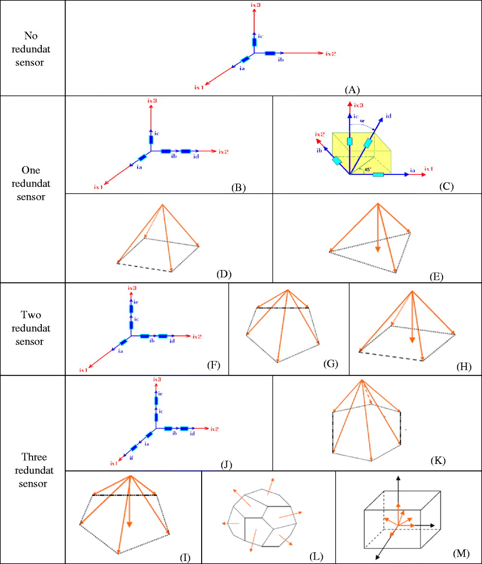
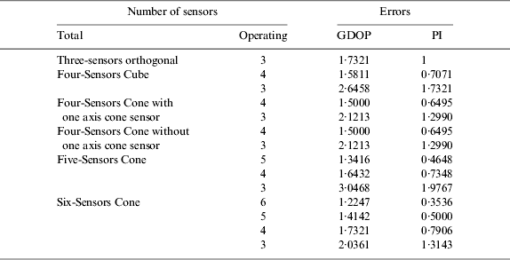
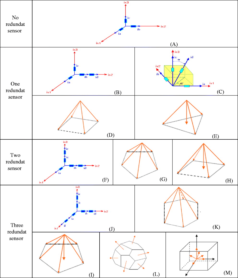
The possible SRIMU configurations are shown in Figure 1. Based on the Equations (12) and (13), for the SRIMU configuration, the effective errors are given in Table 1. For comparison of the errors for different sensor configurations, we suppose the PI error of conventional three-sensors is unity, and we normalize the PI error of another SRIMU with it.
SRIMU Configurations. (A): 3 Orthogonal sensors. (B): 4 Orthogonal sensors. (C): 4 Non-orthogonal sensors (Cube). (D): 4 Non-orthogonal sensors (Cone without one cone axis sensor). (E): 4 Non-orthogonal sensors (Cone with one cone axis sensor). (F): 5 Orthogonal sensors. (G): 5 Non-orthogonal sensors (Cone without one cone axis sensor). (H): 5 Non-orthogonal sensors (Cone with one cone axis sensor). (J): 6 Orthogonal sensors. (K): 6 Non-orthogonal sensors (Cone without one cone axis sensor). (I): 6 Non-orthogonal sensors (Cone with one cone axis sensor). (L): 6 Non-orthogonal sensors (Dodecahedron). (M): 6 Non-orthogonal sensors (3-sensor Cone + 3-sensor Cube).
The comparison of the errors for different sensors configurations

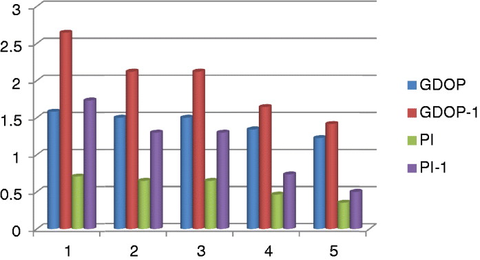
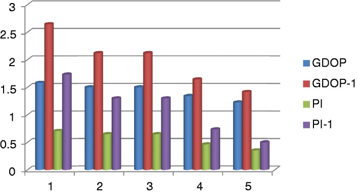
Comparing the third and fourth columns of Table 1, if sensor failures occurred, optimal configurations may not obtain better measurement accuracy in comparison with a non-optimal configuration. Therefore, the selection of a SRIMU configuration is a trade-off between failure detection performance and measurement accuracy under conditions of no sensor failures and sensor failures. Figure 2 shows errors comparing for different sensors configuration in case of failure in one sensor and without any failure.
Errors comparing for different sensors configuration.
3. SYSTEM RELIABILITY
Reliability is the probability that a system will perform for a given time under given conditions. The system is assumed to have been randomly chosen from a group of identical systems; reliability is a characteristic of the group, not of the individual. The reliability of inertial sensors is often estimated by similarity and replaced by test data as early as possible.
Equipment often has a finite life. Some equipment might degrade gracefully, others may fail catastrophically. Bearings and slip rings wear, gas laser gyro cathodes may decay, and a DTG flexure or an accelerometer hinge might break. These failures might call for maintenance (the process of returning the system as closely as possible to its as-new condition); if the system was designed to be reparable but it is no longer economically feasible to repair a system, it has ‘worn out’. The mean life of a population of systems is the average time to ‘wear out’ and the ‘useful life’ of a system is the period between initial operation and the onset of ‘wear out’.
3.1. Mean Time between Failures (MTBF)
If we can repair a failed device such that the repair does not introduce a new failure potential, then the average time that one can expect the device to work before the next failure is the Mean Time between Failures (MTBF). In a test of a large sample, the MTBF is the total operating time of all the samples (not just the failed ones) divided by the number of failures. After a long period, this test should converge on a constant MTBF. The ratio of MTBF to mission time is the probability that the device will allow the mission to be completed. Statistically, 63% of a population of a device will fail in an operating time equal to the MTBF. Failure rate is the reciprocal of the MTBF and is usually expressed in failures per 106 hours.
3.2. Reliability Analysis for SRIMU Configurations
Since the question of reliability plays an important role in the design of INSs, it is well to discuss certain aspects of the problem. Considering first the system redundancy and reliability problem, it is self evident that system reliability for a fixed set of components can be increased by providing the redundancy at as low a level as possible.
We consider next certain of the aspects of component reliability. Although we could address ourselves to the reliability aspects of the INS's components, it is generally recognised that the gyroscopes are the least reliable of the system components. Thus various redundant gyro configurations are considered although the conclusions are certainly valid for other sets of redundant instruments.
To motivate the discussion, consider an IMU with three gyros mounted with their input axes along three mutually orthogonal axes (the triad configuration).
Clearly the system will fail if any one gyro fails. If the gyros are assumed to fail independently and to follow an exponential failure rate, the reliability of such a system is given by the product of the reliabilities of the individual components:
 $${\rm R}_{3{\rm Gyro}} ({\rm t}) = {\rm e}^{ - 3{\rm \lambda t}} = \gt {\rm MTBF}_{3{\rm Gyro}} = \displaystyle{1 \over {3{\rm \lambda}}} $$
where:
R is probability that satisfactory performance will be attained for a specified time period. ${1 \over {\lambda}}} $ is mean time to failure.

Thus to achieve a reliability of 0·95 for 1 year, requires a gyro MTBF of 59 years. In a commercial application some consideration should be given to this aspect of system performance since a ‘cost of ownership’ criterion is generally applied to INS procurement.
If it has been established that gyro redundancy is required for a particular application, the problem still remains of choosing a gyro configuration which gives the maximum reliability for the number of instruments used. This problem has been studied and it finds that symmetric arrays yield optimal performance from a least squares weighting point of view and, in addition, yield maximum redundancy for the number of instruments in the particular array.
3.3. Computing the SRIMU Configuration Reliabilities
To compare reliabilities of various configurations of SRIMU systems, assume that all sensors are single-degree-of-freedom sensors and the failure rate of each sensor is constant and identical for each type of inertial sensor. Then the reliability function of each inertial sensor is given by:
 $${\rm R}({\rm t}) = {\rm e}^{ - {\rm \lambda t}} $$
and:
the MTBF (mean time between failures) is defined as:
 $${\rm MTBF} = \int\limits_0^\infty {{\rm R}({\rm t}){\rm dt} = \displaystyle{1 \over {\rm \lambda}}} $$
The reliability of the redundant sensor system (in the case of non-orthogonal sensors) is given by the following equation:
 $$\scale96%\eqalign{{\rm R}_{{\rm sensor}} ({\rm t}) = [{\rm R}({\rm t})]^{\rm n} + {\rm C}_{\rm n}^{{\rm n} - 1} [{\rm R}({\rm t})]^{{\rm n} - 1} [1 - {\rm R}({\rm t})] + \cdots + {\rm C}_{\rm n}^{{\rm n} - {\rm m}} [{\rm R}({\rm t})]^{{\rm n} - {\rm m}} [1 - {\rm R}({\rm t})]^{\rm m} $$
where:
 $${\rm C}_{\rm n}^{\rm m} = \displaystyle{{{\rm n}!} \over {({\rm n} - {\rm m})!{\rm m}!}}$$
and:
n is the number of sensors in the redundant configuration and m is the number of allowable failure sensors in the redundant system.
Therefore, the reliability of an SRIMU system is given by:
 $${\rm R}_{{\rm SRIMU}} ({\rm t}) = {\rm R}_{{\rm Gyro}} ({\rm t})\cdot{\rm R}_{{\rm Accel}} ({\rm t})$$
For the orthogonal configuration in a conventional IMU, the reliability and MTBF are given by:
 $${\rm R}_{3{\rm Gyro}} ({\rm t}) = {\rm e}^{ - 3{\rm \lambda t}} = \gt {\rm MTBF}_{3{\rm Gyro}} = \displaystyle{1 \over {3{\rm \lambda}}} $$
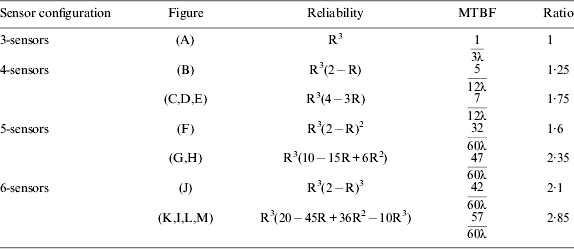
For the configurations shown in Figure 1, the reliability figures and MTBF values are computed. The results are summarized in Table 2. From inspection of Table 2, the reliability of a SRIMU configuration depends on the number of redundant sensors and the failure rate of sensor. The accuracy of SRIMU measurements relies on the sensor installation configurations.
Reliabilities of Several SRIMU Configurations
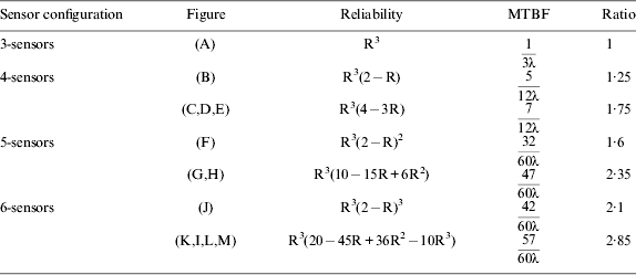
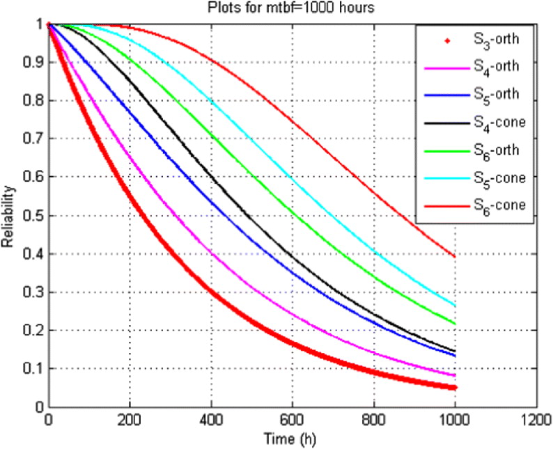
Figure 3 shows plots of equations declared in Table 2. So reliability curves are shown for systems consisting of three, four, five, six orthogonal and cone sensors.
SRIMU configurations reliability curves.
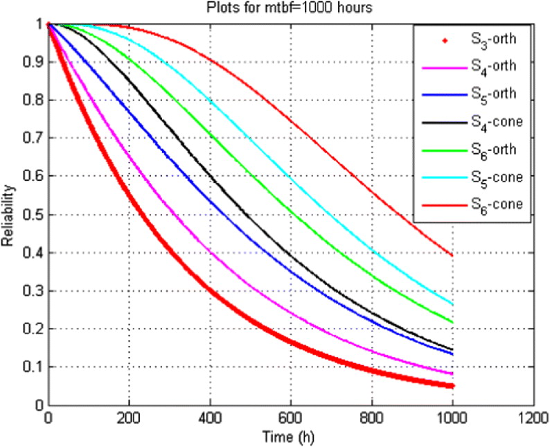
The plots are made under the assumption that any failure can be detected and isolated. Note that the reliability of the non-orthogonal arrays is quite superior to that of the redundant orthogonal arrays.
4. CONCLUSION
In this paper, we analysed the performance of redundant Inertial Measurement Units (IMUs) and their various sensor configurations. This paper gives particularly attractive configurations of four, five and six sensors. These combinations are capable of functioning with any three sensors, of detecting a malfunction with any four, and of isolating a malfunction with any five. We can achieve the best reliability for space Inertial Navigation System (INS) if we use a six-sensor cone configuration. Otherwise, the inertial redundant sensors navigation system with five-sensor cone, six-sensor orthogonal, four-sensor cone, five-sensor orthogonal and four-sensor orthogonal could achieve more reliability than three-sensor orthogonal configuration respectively. The sensor configurations shown not only minimize system error when all sensors are operable, but when only three sensors remain operational, their reliability and accuracy are comparable to a conventional unit of three orthogonal instruments.