

1. INTRODUCTION
Kinematics, the science of pure motion, is concerned with the analysis and synthesis of mechanisms composed of connected rigid elements. It deals with the relative geometric displacements of points and links of a mechanism, without regard to forces that generate those displacements or the physical embodiment that realizes them.
The interest in kinematics has its origins in machines as old as civilization (Ramelli, Reference Ramelli1588), but it was largely invigorated in the 18th century with the invention of the steam engine and the beginnings of the industrial age (Ferguson, Reference Ferguson1962). Initially, designs were produced and analyzed by practitioners in an ad hoc manner, but the pressure for rigorous and systematic performance led, within a few generations, to the establishment of increasingly general methods for geometric analysis and classification of mechanism types (Reuleaux, Reference Reuleaux1876). Many of these ideas form the basis of modern kinematic theory today.
Kinematic synthesis, however, is still largely a challenge. The systematic synthesis of a mechanism for a given purpose is a long-standing problem, and perhaps one of the earliest general synthesis problems to be posed. Robert Willis, a professor of natural and experimental philosophy at Cambridge, wrote the following in his 1841 book The Principles of Mechanisms (Willis, Reference Willis1841):
[A rational approach to synthesis is needed] to obtain, by direct and certain methods, all the forms and arrangements that are applicable to the desired purpose. At present, questions of this kind can only be solved by that species of intuition that which long familiarity with the subject usually confers upon experienced persons, but which they are totally unable to communicate to others. When the mind of a mechanician is occupied with the contrivance of a machine, he must wait until, in the midst of his meditations, some happy combination presents itself to his mind that may answer his purpose.
More than a century later, a rational method for the synthesis of mechanisms is still not clear. Despite great advances in analysis of mechanisms and classification of elementary components, founders of modern kinematic theory wrote “While we may talk about kinematic synthesis, … we really are talking about a hope for the future than a great reality of the present” (Hartenberg Denavit, Reference Hartenberg and Denavit1954). Analytical methods do exist for some special cases of mechanisms (such as serial articulated joints, or certain parallel mechanisms), but not for the general case. Mathematical proofs of existence show that mechanisms can be found to trace any algebraic curve, but their construction is usually impractical. We may often be content with a simpler approximate solution, but it is not clear how to obtain such a solution. The question of rational synthesis of mechanisms is today of increasing importance with the quest for design automation; when seeking computational synthesis methods, no longer can we cloak the design process with the term “creativity.”
1.1. Prior work
There is a large body of recent work on topological optimization of static and compliant structures (see Hassani Hinton, Reference Hassani and Hinton1999; Olhoff Rozvany, Reference Olhoff and Rozvany2001; Bendsoe Siegmund, Reference Bendsoe and Siegmund2002), where a structure is optimized to obtain desired performance across a number of criteria and tradeoffs such as deflection, vibration, crashworthiness, and weight. These methods usually work using a homogenization process, where an initially solid or fully connected structure is gradually eroded by eliminating components or material until the stress levels within the remaining structure approach uniformity (and hence optimality). Evolutionary and homogenization methods have also been applied to design of compliant mechanisms (Fecker et al., Reference Fecker, Ananthasuresh, Kikuchi and Kota1997; Nishiwaki et al., Reference Nishiwaki, Frecker, Min and Kikuchi1998), which are similar to static structures but are deliberately designed for large deflections. These elimination-based methods are inappropriate for kinematic synthesis, however, because kinematic mechanisms function using only rigid links, and therefore exploring fully connected or overconstrained topologies is futile. It is difficult to foresee how complex mechanisms, containing a large variety of components such as gears and actuators, could be constructed by an elimination process starting at some “fully connected mechanism” superset. It is therefore likely that a compositional approach would be more generally applicable to kinematic design.
A number of recent works have used evolutionary computation techniques to automate mechanism design by composition, often in conjunction with designing a controller. The mechanisms designed were usually serial or treelike (Sims, Reference Sims, Brooks and Maes1994; Komosinski Ulatowski, Reference Komosinski and Ulatowski1999; Bongard, Reference Bongard2002; Hornby et al., Reference Hornby, Lipson and Pollack2003), although some of our prior work focused on design of compound mechanisms containing multiple, entangled kinematic loops (Lipson & Pollack, Reference Lipson and Pollack2000). Nevertheless, the capabilities of kinematic synthesis automation and suitable representations remain largely unexplored.
The goal of this paper is twofold: to explore some representations for kinematic synthesis using genetic programming (GP) and to benchmark the performance of these algorithms against a well-established kinematic design problem that has baffled some of the world's greatest inventors for nearly a century: the straight-line problem.
2. MECHANISM REPRESENTATIONS
A key question in preparation for an automated synthesis process is that of representation: how would a kinematic mechanism be encoded such that all possible mechanisms can be described, and what variation operators would be used to explore this space of mechanisms? A kinematic mechanism can be represented as a graph, embedded in two or three dimensions. Edges of the graph represent links, and nodes of the graph represent joints. There are a number of different types of joints [e.g., prismatic or rotary in two-dimensional (2-D), ball, prismatic, cylindrical, or screw, in three-dimensional (3-D)], and a number of different types of links (with different geometries and numbers of attachment points). Here, we focus on planar mechanisms with free (pin) joints. Table 1 shows how more complex mechanism types and components can often be reduced to an equivalent simple pin-joined mechanism.
Some higher level elements and their pin-joined equivalents
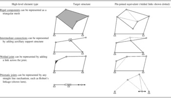
aAdded links shown dotted.
A 2-D mechanism composed of straight links and free joints is directly represented by a graph embedded in the plane. Variation operators could modify this structure directly, but we prefer that these variation operators will be invariant with respect to the number of degrees of freedom (DOF) of the mechanism.
2.1. Kinematic DOF
An important concept in the description of a kinematic mechanism is its number of DOF. The overall number of independent parameters needed to fully specify the state of the entire mechanism is defined as its number of DOF. Some of the mechanisms' nodes may be grounded, and therefore immobile, whereas other nodes are free to move while being constrained by links attaching them to other nodes. In the graph representation described above, it is useful to think of nodes as contributing to the total DOF, and of links as constraints that remove DOF.
The number of DOF of a mechanism can be calculated directly by considering the fact that each node in a planar mechanism has 2 DOF of motion in the plane, and each link eliminates one of these DOF by providing one constraint on the distance between two nodes. The entire mechanism also has 3 rigid-body DOF that can be eliminated by grounding any one of the links. The total DOF of a grounded mechanism with n nodes and m links is thus 2n–m–3. A grounded four-bar linkage (Fig. 1a), for example, has exactly 1 DOF, and its nodes will therefore trace curves. A five-bar mechanism (Fig. 1b) has 2 DOF, and some of its nodes will trace (fill) areas. There may be, however, mechanisms that are overconstrained in some part and underconstrained in another, leading to misleading total DOF count (Fig. 1c). Other mechanisms may have geometrical singularities and degeneracies in their configurations that cause locking or unaccounted free motions. It is therefore impossible to predict the DOF that a general mechanism may have based solely on topological counting arguments.
The degrees of freedom (DOF) of a mechanism: (a) a four-bar mechanism has 1 DOF and some of its nodes trace curves, (b) a five-bar mechanism has 2 DOF and some of its nodes can trace over an area, but (c) some structures are overlapping constraints or have degeneracies that lead to miscalculation of their number of DOF. This structure should be locked, but it is free.

An evolutionary process for kinematic synthesis makes progress by varying and selecting mechanisms. The variation operators can modify the mechanism's graph directly, or may use an indirect encoding (genotype) from which the graph (phenotype) is constructed. Luke and Spector (Reference Luke, Spector and Koza1996) survey a number of different representations used to describe or “grow” computational graphs, such as neural networks. Some methods use context-free grammars, L-systems, and parse trees operating on nodes and edges (e.g., Wilson, Reference Wilson and Grefenstette1987; Kitano, Reference Kitano1990; Boers et al., Reference Boers, Kuiper, Happel, Sprinkhuizen-Kuyper and Wijshoff1993; Gruau, Reference Gruau1994).
Most of the existing representations for encoding graphs generate highly connected topologies that are suitable for computational networks, but which are less suitable for kinematic networks because they overconstrain the motion and create deadlocked mechanisms. Using these representations, the likelihood of generating a mechanism with exactly 1 DOF is vanishingly small. To allow an evolutionary process to explore the space of 1 DOF mechanisms more efficiently, a more suitable representation is required. This representation must have a treelike architecture to be used by standard GP.
A second consideration in the choice of representation is that of evolvability. Many of the representations cited above result in context-sensitive and order-sensitive description of a network. For example, the structure generated by a branch in Gruau's cellular encoding depends on whether it is parsed before or after its sibling branch. If that branch is transplanted by crossover into another tree it may produce an entirely different structure. Such behavior hampers the effectiveness of recombinative operators by precluding the formation of modular components that are discovered by the search in one place and then reused elsewhere. A representation where the structure produced by a branch of the tree is minimally affected by its context may thus be more evolvable.
2.2. Top-down and bottom-up tree representations of kinematic mechanisms
Tree-based representations can describe a set of operations to construct a phenotype in a top-down or bottom-up manner. A top-down representation starts with an initial structure (an embryo) and specifies a sequence of operations that progressively modify it into its final form. Figure 2a shows a top-down tree that specifies the construction of an electric circuit, starting with an initial circuit and recursively replacing circuit segments with serial and parallel arrangements of electrical components (Koza, Reference Koza1992). Each node of the tree is either an operator that modifies the circuit and passes segments to its child nodes, or a terminal electrical component. The specific parallel and serial operators cannot be used for construction of mechanisms as they will immediately create over- and underconstrained kinematic chains. Because of the physics of electric circuits, ordering of children under a parent does not always matter. This tree is thus both order independent and context independent. In a top-down tree, parent nodes must be constructed before their children.
Top-down and bottom-up parse-tree constructions: (a) top-down construction of a circuit and (b) bottom-up construction of a symbolic expression.
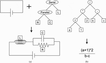
Figure 2b shows a bottom-up construction of a symbolic expression. Here, terminal nodes represent constants or variables, and parent nodes represent mathematical operators. Because of the nature of mathematical expressions, parsing order is important, and swapping order of some child nodes would result in a mathematically different expression. The terms are unchanged, however, by the content of their siblings. This tree is thus order dependent but context independent. In a bottom-up tree, child nodes must be constructed before their parents.
Two tree-based representations for describing kinematic mechanisms are proposed here. Top-down construction of a mechanism starts with an embryonic 1 DOF kinematic basis such as the four-bar mechanism shown in Figure 3a. A tree of operators then recursively modifies that mechanism by replacing single links with assemblies of links with an equivalent DOF, so that the total number of DOF remains unchanged. Two such transformations are shown in Figure 3b: the D and T operators.
Top-down construction of a 1 degree of freedom (DOF) mechanism: (a) an embryonic four-bar mechanism; (b) two operators that change local topology but do not change the number of DOF; (c) operators applied in some sequence will create new mechanism, such as transform a dyad into a triad; and (d) operators can be applied in a tree to transform the embryonic mechanism into an arbitrary mechanism while retaining the original number of DOF.
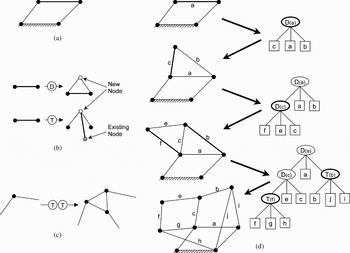
The D operator creates a new node and connects it to both the endpoints of a given link, essentially creating a rigid triangular component. The T operator replaces a given link with two links that pass through a newly created node. The new node is also connected to some other existing node. In both operators, the position of the new node is specified in coordinates local to link being modified. The T operator specifies the external connecting node by providing coordinates relative to link being modified; the closest available node from the parent structure is used. This form of specification helps assure the operators remain as context and order independent as possible. Figure 3c shows how a certain sequence of operators will transform a dyad into a triad. Figure 3d shows how application of a tree of operators to the embryonic mechanism, will transform it into an arbitrary compound mechanism with exactly 1 DOF. Terminals of the tree are the actual links of the mechanism.
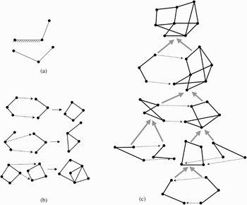
Alternatively, bottom-up construction of a 1 DOF mechanism begins at the leaves of the tree with atomic building blocks and hierarchically assembles them into components. The atomic building block is a dyad as shown in Figure 4a, and has exactly 1 DOF when grounded. The composition operator ensures that the total number of DOF is not changed when two subcomponents are combined, and thus the total product of the tree will also be a mechanism with exactly 1 DOF. When combining two components each of 1 DOF, the resulting assembly will have 5 DOF (1 DOF from each, plus 3 DOF released by ungrounding one of the components). The total DOF is restored to 1 by eliminating 4 DOF through the merging of two point pairs. An example of this process is shown in Figure 4b. Note that points must be merged in a way that avoids overlapping constraints, such as causing two links to merge. The components may need to be scaled and oriented for the merger to work. The ground link of the entire structure is specified at the root of the tree.
Bottom-up construction of a 1 degree of freedom (DOF) mechanism: (a) an atomic building block of a mechanism has 1 DOF when grounded and (b) examples of composition of atomic and higher level building blocks. The composition operator eliminates two vertices, thereby ensuring that the total number of DOF of the compound structure remains exactly one. (c) Composition operators can be applied hierarchically in a tree to aggregate atomic building blocks into increasingly complex kinematic mechanisms, each with exactly 1 DOF.
3. TEST CASE: THE STRAIGHT-LINE PROBLEM
In selecting a test problem to evaluate the performance of a GP using the above representations, we sought a kinematic synthesis challenge that is on par with human inventive capacity. There are numerous ingenious kinematic mechanisms in many everyday products around us, from cars to DVD players and electric toothbrushes (Moon, Reference Moon2004). However, nowhere was a single design challenge so clearly states and persistent as the straight-line problem.
The straight-line problem seeks a kinematic mechanism that traces a straight line without reference to an existing straight line. It is easy to imagine a kinematic mechanism that traces an exact circle, for example, without having a circle prebuilt in to it: a simple link, constrained at one endpoint and tracing at the other endpoint would create an exact circle. Figure 5a shows such a device: a compass. Tracing an exact straight line without reference to an existing straight line is, however, much more difficult. It is a challenge that has occupied inventors for nearly a century. One solution, known as “The Peaucellier” (1873), is shown in Figure 5b.
Mechanisms to trace exact curves. (a) Tracing an exact circle without reference to an existing circle is simple, but (b) tracing an exact straight line without reference to an existing straight line is a challenge that has occupied inventors for nearly a century. The mechanism shown is “The Peaucellier” (1876). All links are shown as crooked sticks to emphasize that the links themselves do not need to be straight; they merely constrain the distance between two nodes.

The straight-line problem was of great practical importance in the 18th and 19th centuries. The invention of the steam engine marked a new era of technological advance, but its early development was plagued with problems of reliability and machining accuracy, leading to both steam leakage around the piston heads and overwhelming friction. One of the big challenges was how to convert the reciprocating linear motion of the double-acting (push–pull) piston into a continuous rotary motion of a wheel. Although the use of a crank and a connecting rod seems trivial today, it was by no means apparent at the time, because machining accuracy was such that the piston head could not sustain side loads well and needed a straight guide to keep it from wobbling and leaking steam. Conventional designs at the time used the reciprocating motion to pump water into a reservoir and turn a waterwheel, or used other complex arrangements of gears and chains. James Watts' first patent (1782) used a rack and sector (Fig. 6a and b).
Some key straight-line mechanisms: (a) Watt's original rack and sector solution in 1782 (Muirhead, Reference Muirhead1854), (b) Watt improvement in 1784, (c) Watt's first straight-line linkage mechanism (Muirhead, Reference Muirhead1854), (d) Robert's linkage in 1841, (e) Chebyshev's linkage in 1867, (f) Peaucellier's linkage in 1873, (g) Silverster–Kempe's linkage in 1877, (h) Chebyshev's combination in 1867, (i) Chebyshev–Evans combination, 1907. From Kempe (Reference Kempe1877).

The real breakthrough in steam engine technology came with the invention of a linkage system to guide the piston in a straight line. In 1784, Watt wrote to his partner Boulton: “I have got a glimpse of a method of causing the piston rod to move up and down perpendicularly, by only fixing it to a piece of iron upon the beam, without chains or perpendicular guides, or untowardly frictions, arch-heads, or other pieces of clumsiness … I think it a very probable thing to succeed” (Muirhead, Reference Muirhead1854). The design is shown in Figure 6c. Years later, Watt told his son: “Though I am not over anxious after fame, yet I am more proud of the parallel motion than of any other mechanical invention I have ever made” (Muirhead, Reference Muirhead1854).
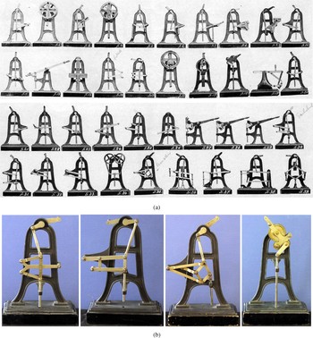
Since the initial inception of the straight-line mechanism, many inventors engaged in improving and creating alternative designs. Figure 6d–i show a number of additional practical designs. The obsession with the straight-line mechanism continued well beyond what its practical usefulness merited, to become a mathematical puzzle in its own right. The challenge continued even after the invention of the perfect mechanism by Peaucellier in 1873, a century after Watt's initial invention. Numerous straight-line mechanisms were proposed, as evident from the 39 different straight-line mechanisms shown in the Voigt catalog (Voigt, Reference Voigt1907) of educational models (Fig. 7a). Cornell University still owns most of these models, which were acquired in 1882 and used in the early engineering curricula; some are shown in Figure 7b. As precision manufacturing improved, the need for straight-line mechanisms diminished, and it is now lost knowledge. Ferguson provides a vivid account of that era (Ferguson, Reference Ferguson1962).
The plethora of straight-line mechanisms: (a) Voight's listing of 39 straight-line mechanisms out of a catalog of teaching models (Voigt, Reference Voigt1907), (b) most of these models were acquired by Cornell University in 1882 and used in the early teaching curriculum. These models are now on display at the museum of kinematics, with videos available online (Saylor et al., Reference Saylor, Walker, Moon, Henderson, Daimina and Lipson2008). [A color version of this figure can be viewed online at journals.cambridge.org/aie]
3.1. Simulating and evaluating straight-line mechanisms
The performance of a given mechanism was evaluated using an in-house kinematic simulator (Lipson, Reference Lipson2004). This simulator approximates the rigid links with stiff elastic springs, and propagates displacements throughout the structure using a relaxational process, gradually reducing elasticity to approximate rigid behavior. The process iterates until the structure reaches equilibrium; if equilibrium is not reached, or if large residual (internal) forces remain, then the mechanism is deemed to be overconstrained or underconstrained in some way. Another way to check for invalid mechanisms is by evaluating the same mechanism several times with slightly perturbed starting conditions. An underconstrained mechanism (with DOF > 1) will not necessarily trace the same curve. It is interesting to note that the number of invalid mechanisms quickly reduces because of selection. The percentage of invalid (unsimulatable) mechanisms over evolutionary time is given in the results.
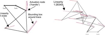
Evaluation of an evolved straight-line mechanism: the mechanism is actuated at an arbitrary handle and the aspect ratios of bounding boxes of node trajectories are measured. One node of the evolved machine on the left traces a curve that is linear to 1:5300 accuracy. The machine uses the principle of Willis (Reference Willis1841), as seen in Figure 6d. The evolved mechanism on the right traces a curve that is linear to 1:28,340 accuracy. [A color version of this figure can be viewed online at journals.cambridge.org/aie]
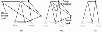
Reductions of mechanisms: complex mechanisms can be reduced to simpler mechanisms with equivalent curve traces by iterative application of two transformations: (a) elimination of excess dyads and (b) swapping of diagonals within rigid subcomponents. Mechanisms (a) and (c) are thus equivalent in the curve that the lower node traces.
Two typical runs: (a) each dot represents an evaluated individual and (b) the percentage of unsimulatable machines is dramatically reduced because of selection.

To measure the extent to which a given mechanism traces a straight line, the mechanism is actuated along its single DOF by applying some small force to one of its ungrounded nodes, selected arbitrarily. The trajectories of all nodes are recorded, and then evaluated for straightness. Straightness is computed as the aspect ratio of a tight bounding box of the trajectory. The length over width of the bounding box provides a fitness criterion that measures the maximum deviation from a straight line, as seen in Figure 8.
Comparison of mechanisms can be difficult, as apparently different machines may be functionally equivalent. Complex mechanisms can be reduced to simpler mechanisms with equivalent curve traces by iterative transformations (Fig. 9): eliminations of excess dyads, and swapping of diagonals within rigid subcomponents. This transformation was applied automatically only to the best of run individuals, although reductions could be applied also during run to reduce bloat, often encountered in GP in other domains.
4. RESULTS
Straight-line mechanisms were evolved using GP operating on trees describing mechanisms in a top-down representation (Fig. 3). We used a population of 100 individuals and fitness proportional selection using stochastic universal sampling. The fitness was the linearity of the most linear curve traced by any of the mechanisms' vertices, when the crank node was turned 45°. Table 2 summarizes key parameters of this run.
GP Parameters

The search progressed in steps of discovery (“Punctuated Equilibria”; Gould & Eldredge, Reference Gould and Eldredge1977), as shown in two typical runs plotted in Figure 10. A variety of mechanisms were produced, most with linearity exceeding 1000 (i.e., a deviation of 1 mm over 1 m) and some as high as 28,000 (35 µm over 1 m) as seen in Figure 8b. Comparing these compound mechanisms to the known classical solutions is difficult, but some clearly infringe on earlier principles such as that of Robert's Linkage (1841), as seen in Figure 8. Two additional results and their trees are shown in Figure 11.
Mechanisms to trace exact curves. (a) Tracing an exact circle without reference to an existing circle is simple, but (b) tracing an exact straight line without reference to an existing straight line is a challenge that has occupied inventors for nearly a century. The mechanism shown is “The Peaucellier” (1876). [A color version of this figure can be viewed online at journals.cambridge.org/aie]

5. CONCLUSIONS
This paper presented the application of GP to the synthesis of compound 2-D kinematic mechanisms. Two tree-based representations were proposed: a top-down representations that modified an initial base mechanism, and a bottom-up representation that hierarchically composes atomic components. Both these representations allow for systematically searching the space of mechanisms with a specified number of degree of freedom. Both representations are order independent and largely context independent, which are desirable properties for evolvability.
Application of a GP to the straight-line problem yielded a number of mechanisms that are competitive with, and in some cases infringe upon, previous known inventions. It is difficult to compare the “inventiveness” of the algorithm to that of James Watt: in all fairness, the genius of James Watt was in the very idea to use a linkage mechanism to guide the piston in a straight line, and to pursue this idea without knowing that a solution existed at all. It is, however, fair to compare the algorithms' performance to that of Watt's successors who tried to synthesize new and improved linkage mechanisms with the same functionality.
The results shown here are preliminary: only the top-down representation was tested, and there are many aspects of the evolutionary process that could enhance these results, including, for example, selection methods, diversity maintenance, bloat prevention, and the use of automatically defined functions. Future work will further examine these issues and their application to more contemporary kinematic synthesis challenges such as the design of mechanisms for robotic locomotion.
ACKNOWLEDGMENTS
This work was supported by the U.S. Department of Energy Grant DE-FG02-01ER45902.
Hod Lipson received BS and PhD degrees in mechanical engineering from the Technion Israel Institute of Technology, Haifa, Israel, in 1989 and 1998, respectively. He is an Associate Professor with the Mechanical and Aerospace Engineering and Computing and Information Science Schools, Cornell University, Ithaca, NY. Prior to this appointment, he was a postdoctoral researcher with Brandeis University's Computer Science Department and a Lecturer with MIT's Mechanical Engineering Department, where he conducted research in design automation. Dr. Lipson is interested in biologically inspired approaches to robotics, as they bring new ideas to engineering and new engineering insights into biology.


