





Introduction
Ice-sheet beds on hard basement rocks below contemporaneous and past ice are commonly rough, with innumerous rock hills of various shapes and sizes (Roberts and Long, Reference Roberts and Long2005; Krabbendam and Bradwell, Reference Krabbendam and Bradwell2014; Lindbäck and Pettersson, Reference Lindbäck and Pettersson2015; Cooper and others, Reference Cooper2019). Here we examine the balance of resisting and ice drag forces that act on such rock hills and consider how the entry of pressurised meltwater into rock fractures changes the balance of these forces. This problem is relevant to subglacial erosion processes. Abrasion and plucking (quarrying) are generally seen as the main mechanisms of subglacial erosion, with subglacial fluvial erosion locally important (e.g. Glasser and Bennett, Reference Glasser and Bennett2004; Alley and others, Reference Alley, Cuffey and Zoet2019). Recently, a further effective subglacial erosion mechanism, glacial ripping, has been recognised to have operated in eastern Sweden (Hall and others, Reference Hall2020; Krabbendam and others, Reference Krabbendam, Hall, Palamakumbura and Finlayson2022), NW Scotland (Hall and others, Reference Hall, Mathers and Krabbendam2021) and possibly eastern Canada (Bukhari and others, Reference Bukhari2021), below Pleistocene ice sheets that covered these areas. Glacial ripping can remove large parts or all of a rock hill such as a roche moutonnée (Hall and others, Reference Hall2020; Krabbendam and others, Reference Krabbendam, Hall, Palamakumbura and Finlayson2022). The process is considered to involve three steps (Fig. 1): (1) hydraulic jacking caused by overpressure of subglacial meltwater entering fractures in the shallow rock mass; (2) glaciotectonic disintegration of rock hills and (3) transport of boulders and deposition as boulder spreads or immature rubble till. Glacial ripping is a ‘mass’ event, involving hundreds to thousands of blocks at more or less the same time, and affecting a large part or the entirety of a rock hill, distinct from classic lee side plucking, which only removes rock one block at a time (Krabbendam and others, Reference Krabbendam, Hall, Palamakumbura and Finlayson2022). While there is good field evidence (summarised below) to support this three-stage mass process (Hall and others, Reference Hall2020, Reference Hall, Mathers and Krabbendam2021; Krabbendam and others, Reference Krabbendam, Palamakumbura, Arnhardt and Hall2021, Reference Krabbendam, Hall, Palamakumbura and Finlayson2022), the theoretical understanding of the process is still limited.
Conceptual model for glacial ripping as a three-stage subglacial erosion mechanism – after Hall and others (Reference Hall2020). Figure © Svensk Kärnbränslehantering. Reproduced with permission.

Here we explore the theoretical basis of the glaciotectonic disintegration of rock hills, subjected to high water pressure events and resultant hydraulic jacking occurring at the ice bed. In the conceptual model it is envisaged that (transient) high pressure water at the ice bed penetrates into fractures in the bedrock below (Hall and others, Reference Hall2020; Krabbendam and others, Reference Krabbendam, Palamakumbura, Arnhardt and Hall2021, Reference Krabbendam, Hall, Palamakumbura and Finlayson2022). This lowers the static friction along these fractures and, if the water pressure in the fracture exceeds the overburden pressure of overlying ice and rock, it leads to hydraulic jacking. Hydraulic jacking in turn results in loss of rock mass strength and local brecciation of the rock hill in question. It may also locally displace blocks upwards, creating sharp edges on the previously smooth, abraded ice bed (Forssberg and others, Reference Forssberg2007; Krabbendam and others, Reference Krabbendam, Hall, Palamakumbura and Finlayson2022). Continuing application of ice drag forces then further disintegrates the rock hill.
At issue is whether the resisting forces of the rock hill or rock obstacle are sufficiently lowered so that the ice drag forces exceed them, allowing disintegration of the rock mass. To address this issue we model: (1) the drag forces exerted by ice creeping past rock obstacles of variable size and shape at the base of an ice sheet; and (2) the resisting forces of rock obstacles with variable size, shape and internal fracture network configurations; and how these forces are affected by high water pressure events. The scenarios are modelled as a function of glaciological variables such as basal water pressure and ice velocity, and geological/topographical variables such as fracture patterns and obstacle size. We then assess the force balance and assume that block movement, and hence glacial ripping, can occur if the drag forces exceed the resisting forces. We thus test if glacial ripping is a physically plausible process, and under what glaciological and geological conditions it may, or may not, operate at the base of an ice sheet.
Setting and summary of field evidence
We base our modelling on examples of glacial ripping in basement gneisses in eastern Sweden (Hall and others, Reference Hall2020; Krabbendam and others, Reference Krabbendam, Hall, Palamakumbura and Finlayson2022), below the retreating Late Weichselian Fennoscandian ice sheet (FIS). The bedrock in the region consists of crystalline basement (‘shield rock’), with variable fracture patterns and fracture spacing, the latter varying from <0.2 to over 5 m (Jern, Reference Jern2004; Krabbendam and others, Reference Krabbendam, Palamakumbura, Arnhardt and Hall2021). Locally, long subhorizontal fractures occur in the shallow (<10 m) bedrock; elsewhere rocks are more massive, or vertical fractures dominate over subhorizontal ones (e.g. Carlsson, Reference Carlsson1979; Goodfellow and others, Reference Goodfellow2019; Krabbendam and others, Reference Krabbendam, Palamakumbura, Arnhardt and Hall2021). In the near-surface bedrock, horizontal stresses are greater than vertical stresses, and these tend to hold vertical fractures tight (Glamheden and others, Reference Glamheden2007; Hökmark and Lönnqvist, Reference Hökmark and Lönnqvist2014), so that the prevailing stress field favours dilation and hydraulic jacking of shallow horizontal fractures.
Fennoscandia was repeatedly glaciated by ice sheets throughout the Pleistocene. The last FIS, with a maximum ice thickness of 3000–3500 m (Quiquet and others, Reference Quiquet, Colleoni and Masina2016), retreated rapidly between c. 15 and 10 ka over eastern Sweden, with a pause during the Younger Dryas. In east central Sweden, ice margin retreat was by calving in a shallow lacustrine or marine setting (Lundqvist, Reference Lundqvist1987; Andrén and others, Reference Andrén, Harff, Björck and Hoth2011), with retreat rates estimated at 300–350 m a−1 (Strömberg, Reference Strömberg1989; Stroeven and others, Reference Stroeven2016). Mapping of shorelines, combined with accurate varve chronology, suggests that sea or lake level during the deglaciation of east central Sweden was ~150–190 m higher than present sea level, implying a significant water depth at the retreating calving margin (Hedenström and Risberg, Reference Hedenström and Risberg2003; Johnson and others, Reference Johnson, Ståhl, Larsson and Seger2010).
Large areas of lowland Sweden show typical landscapes of glacial erosion developed in gneissic basement rocks with abundant whalebacks and roches moutonnées (Hall and others, Reference Hall2019). Over substantial areas such rock hills have been disintegrated by a process interpreted to be glacial ripping (Hall and others, Reference Hall2020). Field evidence for glacial ripping comprises three components (after Hall and others, Reference Hall2020; Krabbendam and others, Reference Krabbendam, Palamakumbura, Arnhardt and Hall2021; Krabbendam and others, Reference Krabbendam, Hall, Palamakumbura and Finlayson2022):
(1) Dilated subhorizontal fractures, locally sediment-filled, indicating hydraulic jacking, affecting the upper 1–13 m of bedrock (Fig. 2a). This includes cases where rock steps were formed on the previously smooth rock surfaces by differential uplift of fracture-bound rock blocks in the substrate (Fig. 2b).
(2) Partially disintegrated rock hills, such as roches moutonnées (Fig. 2c), in which fractures have been dilated, voids and caves have opened, with extensive evidence of block displacement and removal (Fig. 2d). This disintegration typically increases down-ice, but may affect the entire rock hill, involving hundreds of blocks.
(3) Extensive (thousands of square metres) occurrence of boulder spreads; fields of large (1–5 m) angular boulders, normally of the same lithology, with a spatial density of boulders that far exceeds those normally seen in a basement terrain subjected to glacial plucking (Fig. 2e). The boulders have been transported and dispersed subglacially, but with small transport distances, typically <1 km (Fig. 2f), consistent with limited edge rounding.
Field evidence for glacial ripping in eastern Sweden. (a) Dilated, jacked subhorizontal fracture (50 cm high) with sediment-fill in construction excavation, Forsmark nuclear power plant (Leijon, Reference Leijon2005; Figs 5-1). Photo: Göran Hansson. (b) Upward jacked block with rock step, disrupting the abraded surface; temporary excavation AFM 001364, Forsmark (Forssberg and others, Reference Forssberg2007; fig. B5). (c) Small disintegrated roche moutonnée near Grindstugan, Uppsala county. (d) Part of top surface of the large, partially disintegrated roche moutonnée of Bodagrottorna, Gävleborg county. (e) Boulder spread of angular boulders. Gryttjen, Gävleborg county. (f) Aerial photo (© Lantmäteriet) of two small boulder spreads, showing <250 m transport in an SSE direction. Bodagrottorna disintegrated roche moutonnée to the NE. Figure © Svensk Kärnbränslehantering. Reproduced with permission.

Modelling approach
Background and assumptions
A complex process such as glacial ripping is influenced by a wide range of parameters, each with a range of possible values. To focus our modelling, this range of parameters needs to be restricted: some parameters are not explicitly modelled, but are discussed. Field evidence suggests that damage from glacial ripping was particularly effective below the ablation zone, close to the retreating margin of the Pleistocene ice sheets, and thus constituted an intensive phase of subglacial erosion just prior to deglaciation (Hall and others, Reference Hall2020, Reference Hall, Mathers and Krabbendam2021; Bukhari and others, Reference Bukhari2021; Krabbendam and others, Reference Krabbendam, Palamakumbura, Arnhardt and Hall2021, Reference Krabbendam, Hall, Palamakumbura and Finlayson2022). We thus focus on glaciological conditions beneath the last FIS during its late stage of final deglaciation. Direct glaciological controls exerted by this palaeo-ice sheet are evidently not available, but the Greenland ice sheet (GrIS) is also in a state of retreat, so we use observations from the ablation zone of the GrIS as an analogue for the retreating Pleistocene ice sheets.
Relevant assumptions are as follows:
(1) Basal thermal regime. The ice-sheet bed was ‘warm’ or thawed. Abundant abraded surfaces decorated with striae show that abrasion (and hence warm-based sliding) was active prior to deglaciation in eastern Sweden (e.g. Sohlenius and others, Reference Sohlenius, Hedenström and Rudmark2004); ice-sheet models also simulate warm-based conditions close to the retreating margin (e.g. Näslund and others, Reference Näslund, Rodhe, Fastook and Holmlund2003; Patton and others, Reference Patton2017). Similarly, the base of the GrIS ablation zone is thawed (Macgregor and others, Reference MacGregor2016), and ice motion shows a significant component (45–75%) of basal sliding (Ryser and others, Reference Ryser2014).
(2) Ice viscosity. We model ice as a viscous Newtonian medium, with the viscosity as established experimentally by Byers and others (Reference Byers, Cohen and Iverson2012). This makes the treatment simpler (see also Nye, Reference Nye1970; Hallet, Reference Hallet1979), but is also realistic for temperate ice (Colbeck and Evans, Reference Colbeck and Evans1973; Chandler and others, Reference Chandler, Hubbard, Hubbard, Murray and Rippin2008; Byers and others, Reference Byers, Cohen and Iverson2012; Krabbendam, Reference Krabbendam2016). In essence, we thus assume a layer of temperate ice, thicker than the highest rock obstacles. In Greenland, borehole temperature measurements show a 30–100 m thick basal layer of temperate ice at 20–50 km from the margin, whereas close to the margin the entire ice thickness is temperate (Lüthi and others, Reference Lüthi, Funk, Iken, Gogineni and Truffer2002; Ryser and others, Reference Ryser2014; Harrington and others, Reference Harrington, Humphrey and Harper2015; Harper and others, Reference Harper, Meierbachtol and Humphrey2019). The effects of cold ice, with its different rheological behaviour, is discussed but not modelled.
(3) Ice sliding velocity. Patton and others (Reference Patton2017) modelled maximum ice surface velocities of 200–400 m a−1 during the deglaciation of eastern Sweden. In the GrIS ablation zone, basal sliding velocities are c. 50–75% of the surface velocities (Ryser and others, Reference Ryser2014), so we assume a value of ~300 m a−1 as a maximum realistic sliding velocity.
(4) Ice thickness. Although the FIS reached a maximum thickness of c. 3000 m during late glacial maximum conditions (Quiquet and others, Reference Quiquet, Colleoni and Masina2016), field evidence suggests that glacial ripping was particularly active just prior to deglaciation, hence with low ice thickness. In the lower ground in eastern Sweden, ice retreat was dominated by calving in the Baltic Ice Lake, with water depth up to 180 m. We assume an ice thickness of 300 or 600 m.
(5) Basal water pressure fluctuations. Evidence for hydraulic jacking includes dilated and sediment-filled fractures (see section ‘Setting and summary of field evidence’). High water pressures, including overpressure when temporarily exceeding overburden pressure (Pi), have been measured or demonstrated at the base of the GrIS ablation zone in the following settings. Firstly, dramatic supraglacial lake drainage events can lift up the ice surface over several square kilometres (Das and others, Reference Das2008; Doyle and others, Reference Doyle2013) and these represent high-magnitude overpressure events, involving volumes >106 m3 water, resulting in substantial ice–bed separation. Secondly, high-frequency (daily in the melt season), but short-lived (hours), water-pressure fluctuations between 80 and 110% of Pi have been measured in boreholes (Andrews and others, Reference Andrews2014; Claesson Liljedahl and others, Reference Claesson Liljedahl2016; Wright and others, Reference Wright, Harper, Humphrey and Meierbachtol2016; Harper and others, Reference Harper, Meierbachtol and Humphrey2019). The long-term average water pressure in these boreholes is c. 90–95% of Pi, although some boreholes show long-term close to or exceeding 100% of Pi. These water pressure fluctuations are highly localised events (out-of-phase with adjacent boreholes) and thus represent low-magnitude events, involving only small volumes of water, with only localised ice–bed separation. However, they occur repeatedly (tens of times) throughout the melting season. Thirdly, Andrews and others (Reference Andrews2014) noticed an additional setting, where moulins are well-connected to the glacier bed, preventing overpressure to build up. In this regime, frequent water pressure fluctuations occur between 60 and 98% of Pi, with a long-term average of c. 80% of Pi. All three processes are likely to have occurred during deglaciation of the FIS and may have led locally to hydraulic jacking in eastern Sweden. Thus, for modelling purposes we assume that high water pressure events, including overpressure events, occurred at the ice bed near and around the idealised obstacles under discussion. We do not model or discuss the specific dynamics or spatial extent of high water-pressure events in Sweden. We further assume that the normal stress at the ice bed equals the overburden pressure of the ice.
(6) We make the simplifying assumption that the fracture patterns of the bedrock are broadly orthogonal, and dominated by subhorizontal and subvertical fractures. Such patterns are common in basement rocks in Sweden and elsewhere (Talbot and Sirat, Reference Talbot and Sirat2001; DeWandel and others, Reference Dewandel, Lachassagne, Wyns, Maréchal and Krishnamurthy2006; Pless and others, Reference Pless2015; Krabbendam and others, Reference Krabbendam, Palamakumbura, Arnhardt and Hall2021), and near ubiquitous in flat-lying sedimentary rocks. However, we do model two different fracture patterns: (a) a scenario where all fractures are continuous in-plane, and (b) a scenario where subhorizontal fractures occur at different levels (‘stepped’) but joined to subvertical fractures, via T-junctions, thus being discontinuous in a single plane. This is similar to the ‘step-path’ failure mechanisms recognised in large rock-slope failures (e.g. Brideau and others, Reference Brideau, Yan and Stead2009). In-plane rock bridges along a single fracture (Kemeny, Reference Kemeny2003; Hooyer and others, Reference Hooyer, Cohen and Iverson2012; Elmo and others, Reference Elmo, Donati and Stead2018), and parts of the fracture sealed by fracture fills (Shang and others, Reference Shang, Hencher and West2016), also represent discontinuous fractures and may hamper hydraulic jacking. During overpressure events in which hydraulic jacking occurred, some rock bridges were likely broken by hydraulic fracturing, forming longer, more continuous fractures.
Modelling scenarios
The geometry of the ripped bedrock hills, their internal fracture networks and the resultant effects of glacial ripping in eastern Sweden are highly variable. We confine ourselves to model a number of simple scenarios, informed by natural examples, but including some end-member scenarios (Figs 3a–e):
(1) a blunt hemispherical obstacle of intact rock, without a basal fracture;
(2) a blunt hemispherical obstacle with a continuous, subhorizontal basal fracture;
(3) a blunt hemispherical obstacle with a discontinuous basal fracture, formed by steps in the basal fracture system;
(4) an elongate obstacle with subhorizontal fractures and a blunt stoss side, but a large flat top;
(5) a small rock step, caused by the differential uplift of a rock block, which then protrudes above the surrounding rock surface. This scenario is applicable to the smooth, abraded top surfaces of large hills and low relief rock surfaces.
Modelling scenarios 1–5: conceptual geometries; modelled geometries with some parameters indicated – see also Table 1. Figure © Svensk Kärnbränslehantering. Reproduced with permission.

The basis of the modelling is the principle that if the drag force F d exerted by ice flowing past a blunt obstacle exceeds the resisting forces F r of that obstacle, then the obstacle moves or disintegrates:

All variables and constants are also shown in Table 1.
Variables, constants and parameters used

Drag forces for a hemispherical obstacle
Temperate ice is modelled as a viscous Newtonian medium creeping at low velocities (Hallet, Reference Hallet1979; Byers and others, Reference Byers, Cohen and Iverson2012). In this laminar flow regime with very low Reynolds number (Re ≪ 1), also known as Stokes regime, the drag force F d on a spherical particle has been obtained by solving the Navier–Stokes equations (Stokes, Reference Stokes1951; Loth, Reference Loth2008):

where η is the viscosity, U the velocity of the medium and r the radius of a spherical particle. F d is a combination of form drag, which depends on the shape of the particle because it arises from the pressure the fluid exerts on the cross-sectional area of the object perpendicular to the streamlines, and viscous friction (skin) drag, which is due to the tangential shear stress at the particle surface (Leith, Reference Leith1987). In a normal viscous medium, the creep velocity right at the contact is zero (non-slip boundary), and the tangential shear stress at the obstacle surface is substantial. This is patently not the case for a thawed ice–bed contact, where sliding is known to occur with a thin film of water between the obstacle and the ice. Thus, for temperate ice creeping past an obstacle, skin drag may be low. For this reason, some authors suggest that F d = 4πηUr (e.g. Hallet, Reference Hallet1979; Cohen and others, Reference Cohen2005). However, Byers and others (Reference Byers, Cohen and Iverson2012) empirically confirmed that Eqn (2) is broadly valid (with values for the numerical prefactor of 5.5π; 6.9π and 7.5π) for temperate ice. Since we also use the experimental values of ice viscosity from the same experiments (see above), we herein use Eqn (2) as is. However, we cut the sphere in half to model a hemispherical obstacle (Fig. 4) so that:

Principle of applying Stokes law for laminar flow around a sphere to a hemispherical obstacle: (a) laminar flow around a sphere and (b) hemispherical obstacle, in a half space, within a laminar flow field. Area of projected stoss side A st and area of footprint of obstacle Axy are indicated. Direction of ice flow = x. Figure © Svensk Kärnbränslehantering. Reproduced with permission.

We ignore the effects of regelation because the large size of the rock obstacles compared to smaller debris particles diminishes the heat flow effect through the obstacle and thus renders regelation inefficient over length scales greater than a few centimetres (see also Hallet, Reference Hallet1979; Cuffey and Patterson, Reference Cuffey and Patterson2010; Byers and others, Reference Byers, Cohen and Iverson2012).
Note that the ‘sliding laws’ as derived by for instance by Nye (Reference Nye1970; see discussion in Cuffey and Patterson, Reference Cuffey and Patterson2010), are broadly similar in concept, except that these sliding laws integrate obstacle size over a number of obstacles and thus employ a roughness parameter rather than the size of an individual obstacle, and use the overall basal shear stress, rather than the force exerted on an individual obstacle.
Drag forces for a non-hemispherical, elongate obstacle
Viscous drag forces for a non-hemispherical obstacle are more complicated since they depend on the shape of the object, which needs to be quantified with a shape descriptor, which treats the form and skin drag separately (e.g. Leith, Reference Leith1987; Ganser, Reference Ganser1993; Bagheri and Bonadonna, Reference Bagheri and Bonadonna2016; Dioguardi and others, Reference Dioguardi, Mele and Dellino2018). These approaches all assume a non-slip boundary, and thus are not appropriate in our case, because there is certainly slip along a thawed ice–bed contact. To approximate the drag forces on elongate obstacles, we model a geometry where we split the obstacle in (1) a blunt stoss side that faces ice flow, and (2) a flat horizontal top surface parallel to ice flow (Fig. 3d). We assume that (1) the drag force F vd at the stoss side is controlled by the viscous drag acting upon that stoss face (with surface A st) and controlled by a form of Stokes law and that (2) the drag forces F cf on the flat top surface area are controlled by a simple friction law acting on the top surface (with surface Axy). This ice–rock friction is complex in detail, and different from normal rock–rock friction, because of the presence of rock debris particles between the ice and the bed, variations in concentration and particle size of the debris at the ice bed, and ice deformation and melting around the particles (Hallet, Reference Hallet1979; Emerson and Rempel, Reference Emerson and Rempel2007; see also discussion in Schweizer and Iken, Reference Schweizer and Iken1992). Nevertheless, integrated over a large area, the concept of bulk Coulomb friction appears to be valid (Cohen and others, Reference Cohen2005; Emerson and Rempel, Reference Emerson and Rempel2007; McCarthy and others, Reference McCarthy, Savage and Nettles2017), and is used herein:

where μ ir is the bulk friction coefficient on the ice–rock contact. We take μ ir at 0.05, at the lower end of experimentally obtained values (from Cohen and others, Reference Cohen2005; Emerson and Rempel, Reference Emerson and Rempel2007; McCarthy and others, Reference McCarthy, Savage and Nettles2017); effects of higher friction coefficients as measured by Emerson and Rempel (Reference Emerson and Rempel2007) are not modelled but will be discussed. The normal force F iz exerted by the overlying ice is a function of thickness and density of ice (cryostatic pressure P i), the water pressure P w and the horizontal surface area Axy over which it operates as follows:

The horizontal surface Axy is approximately equal to the surface area of the basal fracture of the rock obstacle. As we wish to explore the effects of relative overpressure P w/P i (in essence the potential effects of hydraulic jacking), this is rewritten as:

where g is the gravitational constant, h i the ice thickness and ρ i the density of ice. Total friction on the flat surfaces then becomes:

Note that Coulomb friction F cf will approach zero if P w approaches P i; since a frictional force cannot be negative, Eqns (5)–(7) are thus only valid for P w ≤ P i.
The viscous drag F vd acting on the stoss side can be approximated by assuming that it is controlled by the square root of the vertical surface area that faces up-ice (the projected ‘stoss-side surface area’ A st, which is half the surface area of a circle with radius r, or the width W multiplied by height H for a rectangular obstacle):

The viscous drag component then becomes ((3) combined with (8)):

The total drag forces of a non-hemispherical obstacle is then ((7) and (9)):

For a rectangular cuboid-shaped obstacle, with width W, height H and length L this becomes:

Resisting forces for a hemispherical obstacle without fractures
If the rock obstacle is poorly fractured, for instance if the rock hill is smaller than the vertical fracture spacing in the local bedrock, or if no continuous subhorizontal fractures are present (Fig. 3a), the resisting force of intact rock F rr is controlled by the intact rock strength as follows:

where τ r is the shear strength of intact rock, and A r the surface area of the potential shear plane of the intact rock. Shear strength values for intact rock are rarely measured, in contrast to uniaxial compressive strength (UCS) and tensile strength. Singh and others (Reference Singh2017) obtained shear strength of between c. 10 and 35 MPa for different gneisses. Shear strength is typically 20–30% of UCS, and about twice the tensile strength. Rock mechanic tests on rocks near Forsmark yielded a range of 160–370 MPa for UCS and 10–18 MPa for tensile strength (Glamheden and others, Reference Glamheden2007), suggesting shear strength range of 20–60 MPa. We take a conservative value of ~20 MPa for τ r, as in nature rocks may contain micro-structures, which lower the shear strength.
Resisting forces for a hemispherical obstacle with continuous basal fracture
If a rock hill contains fractures – as most do – its rock mass strength is lower than that of intact rock. Rock mass strength is complex, so we consider the simple scenario of an obstacle with a single continuous subhorizontal fracture at its base (Fig. 3b). The resisting force F rj along this fracture can be defined by:

where μ rr is rock–rock friction coefficient along the basal fracture, and F rz the normal force acting on the basal fracture. Rock–rock friction coefficient concerns the sliding of two rock blocks along a fracture (different from the ice–rock friction discussed previously) and varies with rock type and fracture roughness; for natural fractures in gneissic rocks Ramana and Gogte (Reference Ramana and Gogte1989) report a range of 0.64–0.77; Glamheden and others (Reference Glamheden2007) report a range of 0.48–0.77, with a mean of 0.67, for rocks at Forsmark. We take a value of 0.7. We ignore fracture cohesion, since hydraulic jacking will have broken any such cohesion.
The normal force F rz has two components:

where F bz is the buoyant weight of the rock above the fracture and F iz is any force (weight) exerted by the overlying ice (as per Eqn (6)). The drag force exerted by ice flowing vertically downwards due to basal melting is ignored: while it is potentially important for small (centimetre-sized) debris particles under conditions of fast basal melting (Cohen and others, Reference Cohen2005; Byers and others, Reference Byers, Cohen and Iverson2012), it becomes very small for metre-sized obstacles (Krabbendam and Hall, Reference Krabbendam and Hall2019).
The buoyant weight of the block is:

where V is the volume of the block, ρ r the density of rock and ρ w the density of water. The total resisting force is then (Eqns (13), (14) and (6)):

For a hemispherical obstacle, as a direct function of r (with V = (2/3)πr 3 and Axy = πr 2), this becomes:

For a rectangular cuboid-shaped obstacle, with width W, height H and length L, this becomes:

Effect of variable transmissivity of basal fractures
Thus far, it is assumed that the water pressure within a basal fracture equalises instantaneously with pressure fluctuations at the ice–bed contact, and leads to hydraulic jacking if relative overpressure P w/P i, exceeds 1, but this only happens if the fracture is highly transmissive (in the hydrological sense). Fracture transmissivity, however, is extremely variable in nature. Low transmissive fractures, for instance tight fractures or fracture planes with many rock bridges, would dampen the fluctuating water pressures in the fracture, and hence lower the peak water pressures within the fracture (e.g. Neupane and others, Reference Neupane, Panthi and Vereide2020). The water pressure in such fractures will remain close to the long-term average (e.g. 80–95% of Pi, depending on the long-term glaciohydrology of the relevant sector in the ice sheet) but not rise above 100%, and thus not cause hydraulic jacking. Fracture transmissivity can vary in nature easily by many orders of magnitude. Instead, we introduce dimensionless transmissivity factor T j to model the effects of variable transmissivity along basal fractures, shown here for a hemispherical obstacle (Eqn (15b)):

Resisting forces with discontinuous basal fracture and some intact rock
Fracture networks in the basement rocks of eastern Sweden (and elsewhere) are highly variable, and continuous subhorizontal fractures at the base of an obstacle are not ubiquitous: in various quarries and natural outcrops it was observed that subhorizontal fractures occur at different levels and are hence discontinuous (or: ‘stepped'); in other sections subvertical fractures are dominant over subhorizontal fractures (Krabbendam and others, Reference Krabbendam, Palamakumbura, Arnhardt and Hall2021). This variability is modelled as a hemispherical obstacle where the base constitutes part intact rock and part fracture (Fig. 3c). The total resisting force F r is then the resisting force of the fracture plus that of intact rock, proportional to the area occupied by the basal fracture A j and intact rock A r respectively:

In proportion to area, this becomes:

So that, using Eqns (10) and (14):

and hence for a hemispherical obstacle:

Results
Different scenarios are calculated below and interpreted. For each scenario, both drag and resisting forces are calculated. Lines where drag force equals resisting force (F d = F r) are plotted for different obstacle radii as a function of ice sliding velocity and relative water pressure. Above the line, F d > F r and the obstacle may be moved or disintegrated by the ice; below the line F d < F r so one would expect the obstacle to remain in place.
On all relevant graphs (Fig 5-11), boxes with plausible glaciological conditions are indicated. These are constrained as water pressure varying between 60 and 105%, as measured below the GrIS (Andrews and others, Reference Andrews2014; Claesson Liljedahl and others, Reference Claesson Liljedahl2016; Wright and others, Reference Wright, Harper, Humphrey and Meierbachtol2016), and maximum sliding velocities of 300 m a−1.
Drag forces F d (solid lines) and resisting forces F r (dashed lines) as a function of sliding velocity U, for a hemispherical obstacle without basal fracture, for obstacles with radii 1–5 m; Eqns (3) and (11). Intact rock strength τ r taken at 20 MPa. Figure © Svensk Kärnbränslehantering. Reproduced with permission.

Scenario 1: hemispherical obstacle without fractures
In hemispherical obstacles without basal fractures (Fig. 3a), the drag force F d increases linearly with sliding speed U (Eqn (3)), whereas the resisting force F r is constrained by the intact rock strength, independent of any glaciological parameter (Eqn (11)). The resisting forces generally exceed the drag forces, even for very high sliding velocities (Fig. 5). Small obstacles may fail at very high sliding velocities (>1700 m a−1), velocities that are not likely to occur on a hard-bedded ice sheet. There is no dependency on ice thickness.
Interpretation of scenario 1
This end-member scenario shows that sliding ice cannot realistically disintegrate rock hills without subhorizontal fractures. In nature such rock hills will be eroded by abrasion alone, and form smooth whalebacks as opposed to roches moutonnées. The height of such hills is constrained by the vertical fracture spacing of the bedrock, which is normally <5–10 m (Jern, Reference Jern2004; Krabbendam and others, Reference Krabbendam, Palamakumbura, Arnhardt and Hall2021), so this scenario is likely only applicable to low (<5 m) hills.
Scenario 2: hemisphere with continuous, transmissive basal fracture
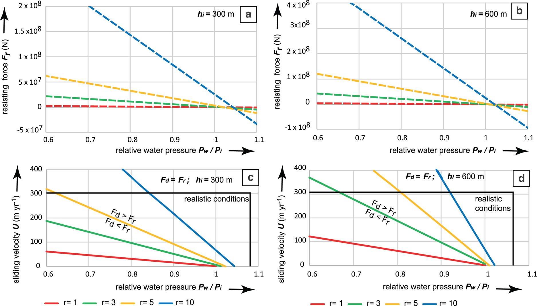
In hemispherical obstacles with continuous basal fractures (Fig. 3b), the resisting forces are controlled by the Coulomb rock–rock friction along the basal fracture (Eqns (12) and (15b)). They decrease linearly with relative water pressure P w/P i, and become zero just beyond the point of flotation (P w = P i), because of the buoyant weight F bz of the obstacle (Figs 6a, b; shown for ice thickness of 300 and 600 m). Drag force F d increases linearly as a function of sliding speed U (Eqn (3)), as in scenario 1 (Fig. 5). Lines of equal drag and resisting force as a function of sliding velocity and relative water pressure for this scenario are given by combining Eqns (3) and (15b):

(a) Resisting forces (N) as a function of relative water pressure P w/P i, for hemispherical obstacles with radii 1–10 m; ice thickness 300 m; Eqn (15b). (b) Same as (a), but ice thickness is 600 m. (c) Lines of equal drag and resisting forces (F d = F r) as a function of sliding speed U and relative water pressure P w/P i, for hemispherical obstacles with radii 1–10 m; Eqn (21). Above the lines, blocks can move, below the lines, blocks cannot move. Box indicates realistic conditions, e.g. water pressure variations between 60 and 105%, and sliding speeds <300 m a−1. (d) Same as (c), for ice thickness 600 m. Figure © Svensk Kärnbränslehantering. Reproduced with permission.
As function of sliding speed, F d equals F r if:

Interpretation of scenario 2
The plots (Figs 6c, d) show that under a wide range of realistic conditions (boxes in graph), blunt, hemispherical obstacles with a continuous basal fracture can be removed by sliding ice. Small obstacles are considerably easier to move than large obstacles. Block removal can occur without overpressure: a small obstacle (r = 3) can be removed at sliding speeds of 200 m a−1, with P w/P i = 0.9; these are fairly normal circumstances for ice sheets. Ice thickness has only a minor effect: a doubling of the ice thickness leads to slightly higher resisting forces, but at higher water pressures this has little effect, and in the further modelling we only model with ice thickness of 300 m. In the case of overpressure (e.g. P w/P i = 1.05, which has been observed below the GrIS), all obstacles would be removed regardless of size. Given that the base of the ablation zone of the GrIS is rough (e.g. Lindbäck and Pettersson, Reference Lindbäck and Pettersson2015; Cooper and others, Reference Cooper2019), and there is still a residual terrain roughness (relative relief) with amplitudes of 5–20 m in eastern Sweden with a multitude of surviving roches moutonnées (Hall and others, Reference Hall2019), this scenario is not realistic as a general case. The critical assumption in this scenario, namely that of a perfectly continuous and horizontal basal fracture in which P w equalises perfectly with P w at the ice–bed interface, is likely not common in basement gneiss terrain, and should be seen as an idealised end-member scenario.
Scenario 3a: hemisphere with part intact rock and part basal fracture
This scenario considers a rock hill with a discontinuous basal fracture, with part of the basal foot print comprising intact rock (Fig. 3c), the strength of which is controlled by the shear strength τ r of intact gneiss. We take a value of 20 MPa: weaker rocks will have lower values. Lines of equal drag and resisting force are then given by combining Eqns (3) and (19b):

Interpretation of scenario 3a
The graph (Fig. 7a) plotting resisting force as a function of the proportion of intact rock versus basal fracture at the base of the hemisphere (for P w = P i, i.e. flotation) shows that even a very small proportion (A r = 5–10%) of intact rock has a dramatic effect on the resisting forces. The points show the drag force exerted by ice sliding at 300 m a−1 for the different radii, taken as a maximum. For large hemispheres (r = 5–10 m), blocks cannot move if c. 10% of the footprint is occupied by intact rock, for smaller blocks this can increase up to 15–20%. On the graph showing sliding velocity versus relative water pressure for equal drag and resisting forces (Fig. 7b) it is clear that larger (>3 m) hemispheres in essence cannot be moved under realistic conditions (box) if intact rock occupies more than 5% of the footprint. Overall, this shows that intact rock offers far more resistance than a continuous transmissive fracture. It also implies that irregularities on basal fractures, such as a small up-ice facing step, can effectively ‘lock’ an obstacle in place.
(a) Resisting forces as a function of the proportion of basal footprint of hemisphere (radii 1–10 m) occupied by intact rock A r/Axy, for P w = P i (flotation); Eqn (19b). Points are the maximum drag forces for sliding speeds of 300 m a−1. (b) Lines of equal drag and resisting forces (F d = F r) as a function of sliding speed U and relative water pressure P w/P i, for hemispherical obstacles with radii 1–10 m with 5% of footprint occupied by intact rock; Eqn (22). Above the lines, blocks can move. Box indicates realistic conditions. Figure © Svensk Kärnbränslehantering. Reproduced with permission.

Scenario 3b: hemisphere with low-transmissivity basal fracture
The effects of limited fracture transmissivity are assessed by varying a transmissivity factor T j; T j = 1 for perfect transmissive fractures in which water pressure equalises instantaneously with water pressure fluctuations at the ice–bed contact; T j = 0 for completely tight, clogged fractures, that remain unconnected to the ice bed, as per Eqn (16).
Interpretation of scenario 3b
From the graphs (Fig. 8), it is evident that fracture transmissivity is an important factor. A lower transmissivity index limits the maximum pressures within the fractures (and also hampers hydraulic jacking), so that resisting forces are not lowered during water pressure fluctuations at the ice bed. In the balance of drag and resisting forces, this implies that much higher sliding speeds would be required to mobilise roches moutonnées. With transmissivities below 0.6, mobilisation becomes unrealistic.
Effect of limited transmissivity along basal fractures; ice thickness 300 m; hemispherical obstacle with r = 5. (a) Resisting force in N versus relative water pressure, with transmissivity factor T j varying between 0.4 and 1; Eqn (16). (b) Lines where drag forces equal resisting forces (F d = F r) as a function of sliding speed U and relative water pressure P w/P i, for hemispherical obstacles with 5 m radius, with transmissivity factor T j between 0.4 and 1; Eqn (21) with T j, as per Eqn (16). Above the lines, blocks can move. Box indicates realistic conditions. Figure © Svensk Kärnbränslehantering. Reproduced with permission.

Scenario 4: elongate obstacle with continuous basal fracture
For an elongate, flat-topped cuboid obstacle, the drag and resisting forces are expressed in terms of length L, width W and height H of the obstacle. The drag force is a combination of viscous drag F vd acting on the stoss surface area with surface H × W, and Coulomb friction F cf acting on the flat top surface (Fig. 3d) with surface L × W, and being dependent on the relative water pressure, as per Eqn (10b). The resisting force is a function of the mass of the obstacle, with volume H × W × L, and the normal stress exerted by the ice acting on the top surface, with surface area L × W, as per Eqn (15c).
The graph for an obstacle with fixed height (2 m), but variable length (Fig. 9a), shows that while the total drag force F d depends somewhat on the length of the obstacle, this dependence is weak. This shows that most of the drag force is provided by the viscous drag acting on the stoss side (dependent on the stoss surface area), whereas Coulomb friction on the top surface (which increases with increasing area of the top surface and hence length) only makes a minor contribution to the total drag force. Figure 9b shows that the drag forces decrease slightly with increasing water pressure, as the Coulomb friction drag component is decreasing.
(a) Drag forces (N) as a function of length of an elongate obstacle, for different relative water pressures; W = 5, H = 2 m, h i = 300 m, sliding velocity U = 200 m a−1; Eqn (10b). (b) Drag forces as a function of relative water pressure, for obstacles with different lengths; other conditions same as (a); Eqn (10b). (c) Resisting forces (dashed lines; Eqn (15c)) and drag forces (solid lines; Eqn (10b)) as a function of length of a rectangular obstacle (W = 5, H = 2 m), for different relative water pressures P w/P i; ice thickness 300 m; ice sliding velocity 200 m a−1. (d) Lines of equal drag and resisting forces (F d = F r) as a function of sliding speed U and relative water pressure P w/P i, for rectangular obstacles; Eqn (23). Above the lines, blocks can move. Box indicates realistic conditions. (e) Lines of equal drag and resisting forces (F d = F r) as a function of sliding speed U and obstacle length, for different relative water pressures P w/P i (0.8–1.05); Eqn (23). Figure © Svensk Kärnbränslehantering. Reproduced with permission.

Lines of equal drag and resisting forces as a function of sliding velocity become (combining Eqns (10b) and (15c)):

For simplicity, we test an elongate rock hill with W = 5 m and H = 2 m, but with variable length, noticing that the width plays little role. However, drag forces are little affected by the obstacle length; the resisting forces are strongly dependent on it: as a consequence longer obstacles are more difficult to move than shorter ones (Fig. 9c). Nevertheless, as water pressure in the fractures increases, increasingly long obstacles can be moved (Figs 9d, e): at flotation (P w = P i) within the fractures, long obstacles can be removed at sliding velocities of 50–100 m a−1.
Interpretation of scenario 4
Long obstacles are more difficult to remove than short obstacles: removal requires high sliding velocities and high water pressures in basal fractures: at flotation (P w = P i), elongate obstacles up to 100 m can be removed at sliding velocities of 200 m a−1, provided that basal fractures are transmissive and continuous.
Scenario 5: rock steps on a flat surface
In this scenario we look at the flat-topped surface, which may be part of a larger rock hill, or a low-relief rock surface. Overpressure and hydraulic jacking can partially uplift a single block (Leijon, Reference Leijon2005; Forssberg and others, Reference Forssberg2007), so that a small rock step, with an up-ice facing stoss side, protrudes above the previously flat surface (Fig. 2e). The drag force on that flat-topped surface, that previously only comprised of Coulomb friction, now has an added component of viscous drag acting on the up-ice facing rock step (Fig. 3e). The question is whether this added viscous drag force is sufficiently high to be able to disintegrate the top surface of the rock.
The drag force exerted on the top surface, with a rock step with height H s is given by:

where Ln is the total length of the row of blocks down-ice of the uplifted block (Fig. 3e). Since the rock mass is already opened up to allow hydraulic jacking we assume a transmissivity of 1. The resisting forces of the row of blocks down-ice from the uplifted blocks is given by:

Lines of equal drag and resisting forces as a function of sliding velocity become (Eqns (1), (24) and (25)):

Interpretation of scenario 5
The drag forces exerted on a flat surface rise rapidly when a small (c. 0.1 m high) rock step is created (Fig. 10a), due to the increase in viscous drag. This relationship is proportional to the inverse of the square root of the height of the rock step. Clearly, the drag forces exerted on a small step are significant. Interestingly, drag forces drop slightly with higher water pressures (Fig. 10b), because Coulomb friction on the top surface decreases with increasing water pressure. The lines of balanced drag and resisting forces (Fig. 10c) show that a series of blocks with cumulative length of blocks of <10 m can be removed with sliding velocities <200 m a−1 when a 0.1–0.4 m high rock step is introduced. Under overpressure (P w/P i = 1.02 as shown in Fig. 10d), such block removal can occur at sliding velocities <100 m a−1. The introduction of a rock step by hydraulic jacking thus radically increases the drag forces exerted on smooth, flat rock surfaces, and may thus assist in glaciotectonic disintegration of larger rock hills.
(a) Drag forces (N) on a flat surface with a rock step, as a function of height of rock step H s, for different ice velocities; Eqn (24). Width and height of blocks are 5 and 2 m; ice thickness = 300 m, P w/P i = 0.9. (b) Same as (a), with P w/P i = 1.02 (2% overpressure). (c) Lines of equal drag and resisting forces (F d = F r) as a function of sliding velocity and height of rock step, for different cumulative length of blocks, P w/P i = 0.9; Eqn (26). (d) Same as (c), with P w/P i = 1.02 (2% overpressure). Figure © Svensk Kärnbränslehantering. Reproduced with permission.

Discussion
Favourable conditions for glacial ripping
We modelled the drag and resisting forces acting on rock hills of various sizes and shapes, and how variable water pressures in fractures affect resisting forces and lead to glaciotectonic failure of the rock mass. Ice drag forces increase with ice sliding velocity, so fast-flowing ice can remove larger or more resistant rock hills than slow-moving ice. Ice drag forces also increase with the radius of a hemispherical obstacle (or the stoss-side surface area), so that high rock hills are more vulnerable to removal than low, streamlined ones. This is consistent with (1) observations that hard beds of palaeo-ice streams are typically streamlined along the palaeo-ice flow lines (Bradwell, Reference Bradwell2013; Krabbendam and others, Reference Krabbendam, Eyles, Putkinen, Bradwell and Arbelaez-Moreno2016); and (2) the absence of high, blunt roches moutonnées with clear continuous basal fractures in eastern Sweden.
Resisting forces are a function of the shape and size of the hill, the fracture pattern of the rock hill (in particular the presence of continuous subhorizontal fractures) and the (peak) water pressure within the fractures. Our modelling indicates that a rock hill without a continuous subhorizontal fracture cannot be moved under plausible subglacial conditions. Such a rock hill is likely to be eroded by abrasion alone, forming whalebacks.
In contrast, a rock hill with a continuous, smooth subhorizontal fracture is easily removed by sliding ice at relatively low sliding velocities, even without overpressured water. However, long, smooth fractures are probably rare in nature, in particular in basement gneisses: rock bridges, up-ice facing steps in the subhorizontal fractures, or indeed very rough fracture surfaces (cf. Barton and Choubey, Reference Barton and Choubey1977) all increase the resisting forces, hindering rock removal. Thus, such a scenario is likely only applicable to small, blunt rock hills: an example is the glacial modification of granite tors by removal of superstructure to leave low-profile plinths (Hall and Phillips, Reference Hall and Phillips2006).
Our modelling shows that elongate rock hills have a higher resisting force, due to the larger rock mass resting on the basal fracture, and greater likelihood of mentioned irregularities along basal fractures. Increased water pressures within a continuous basal fracture greatly reduce resisting forces of a rock hill. Disintegration of larger and/or elongate rock hills, or with more rough basal fractures is thus possible, in particular if pressure fluctuations result in hydraulic jacking. Hydraulic jacking will thus act as a trigger for glaciotectonic deformation. Favourable glaciological conditions for hydraulic jacking include high duration, volume and amplitude of overpressure events at the ice bed. Partial disintegration of a larger rock hill may also occur if hydraulic jacking uplifts a single block, creating a small rock step protruding above the flat top surface. Such a small step dramatically increases the drag forces exerted on the top surface and can aid (partial) disintegration of that rock hill, even if the hill as a whole is too resistant to be moved.
Glacial ripping is thus plausible under certain favourable conditions: a combination of fast ice sliding velocities (>50 m a−1), high water pressures within fractures and favourable fracture patterns in the rock hill, in particular continuous subhorizontal fractures. The glaciological conditions necessary for glacial ripping are not unusual for the base of an ice sheet. In general, sliding velocities of an ice sheet increase towards the margin (Joughin and others, Reference Joughin, Smith, Howat, Scambos and Moon2010; Patton and others, Reference Patton2017), as do the frequency and magnitude of overpressure events (e.g. Claesson Liljedhal and others, Reference Claesson Liljedahl2016), so that glacial ripping is more likely near the margin and at the end of a glaciation, consistent with field evidence in Sweden. However, given a certain maximum relative overpressure (say 110%; Wright and others, Reference Wright, Harper, Humphrey and Meierbachtol2016), the maximum depth of overpressure within the rock is limited to ~3% of ice thickness, which diminishes the effectiveness of hydraulic jacking at low ice thickness.
Favourable geological conditions include the presence of transmissive and continuous basal fractures. Long transmissive subhorizontal fractures do occur in basement rock, but only locally so (Carlsson, Reference Carlsson1979; Follin and others, Reference Follin2007; Goodfellow and others, Reference Goodfellow2019; Krabbendam and others, Reference Krabbendam, Palamakumbura, Arnhardt and Hall2021). Such conditions, however, are common for flat lying sedimentary rocks, where subhorizontal bedding planes take the role of the basal fractures. Glacial ripping events have been documented in such rocks in NW Scotland and Ontario respectively (Bukhari and others, Reference Bukhari2021; Hall and others, Reference Hall, Mathers and Krabbendam2021).
The glaciological conditions favourable for glacial ripping (thawed base, fast sliding velocity, high water pressures), are likely to cause lee side cavitation so similar conditions are also favourable for plucking. Cavitation makes little difference to the drag forces, as these are generated at the stoss side of the rock hill or rock steps. However, cavities represent reservoirs with water available to enter fractures, so the presence of cavities should facilitate hydraulic jacking. The presence of cavities may also have other, more complex but secondary, effects on the force balance discussed here. Some, but not all, observed disintegrated roches moutonnées in eastern Sweden show increased disintegration towards the presumed cavities (Krabbendam and others, Reference Krabbendam, Hall, Palamakumbura and Finlayson2022), which can be partially explained by water entry from lee side cavities.
Effects of non-modelled parameter variability
For some parameters, variability has not been modelled explicitly, but their effects can be discussed qualitatively given the relative simplicity of the equations.
Although we model ice as a Newtonian medium with a fixed viscosity appropriate for temperate ice, it is possible that cold ice overlies a sliding ice base, separated by a thin layer (<1 m) of temperate ice. In that case, the effective viscosity of ice creeping around the obstacles is much higher, possibly by a factor of 10 or more (Glen, Reference Glen1955; Morgan, Reference Morgan1991; Krabbendam, Reference Krabbendam2016). In such a situation, the drag forces on the rock obstacle would be much higher. While ice sliding velocities may be lower in such a scenario, we note that a sliding velocity of 10 m a−1 with a high-viscosity ‘cold-ice rheology’ would exert drag forces of similar magnitude as a sliding velocity of 100 m a−1 with a ‘temperate-ice rheology’, as per Eqn (3).
Ice–rock friction coefficient was taken at 0.05, but higher values (up to 0.4) have been measured in experiments with large debris particle size and high particle concentrations (Emerson and Rempel, Reference Emerson and Rempel2007). A higher ice–rock friction coefficient would result in higher drag forces exerted on the rock obstacles and thus potentially aid glacial ripping, although this effect diminishes at high water pressures at the ice bed (Eqns (10a) and (10b)).
Rock–rock friction coefficient along the fractures was taken at 0.7, which is average for basement rocks. Many other rock types show a rock–rock lower friction coefficient (0.4–0.6; Ramana and Gogte, Reference Ramana and Gogte1989), which would evidently facilitate glacial ripping. The converse is also the case: a higher fracture roughness would increase the friction coefficient, while very high fracture coefficients are transient to a situation with part intact rock (e.g. scenario 3a), or a rock bridge. Fracture roughness and rock–rock friction thus potentially play an important role in controlling glacial ripping, but are poorly constrained in the field, and difficult to predict.
Intact rock strength was taken as the average for basement gneisses. Gneisses, however, are among the strongest rocks occurring in bulk at the Earth surface: most other rock types will have a lower intact rock strength, thus potentially facilitating glacial ripping. A number of papers have recorded a form of glaciotectonic disintegration affecting the top few metres of weaker bedrock such as mudstone or sandstone (e.g. Croot and Sims, Reference Croot and Sims1996; Hiemstra and others, Reference Hiemstra, Evans and Cofaigh2007). On the other hand, the effect of the intact rock strength in the case of a stepped fracture geometry is so pronounced (see scenario 3a), that such as step will still hamper glacial ripping except for the weakest rocks (e.g. shales, chalk). Such rocks, however, are also vulnerable to abrasion and plucking to such a degree that a distinction between erosion mechanisms may become less meaningful (Krabbendam and Glasser, Reference Krabbendam and Glasser2011).
Fracture transmissivity and in-plane rock bridges
In most modelled scenarios, glacial ripping requires high water pressure to penetrate the fractures in the shallow rock mass: such penetration depends on the duration, number and amplitude of high-pressure events at the bed, but also on the fracture transmissivity. Low-transmissivity fractures attenuate water pressure transients at the ice–bed, and water pressure within the fracture may not equalise rapidly enough to result in overpressure within the fracture, even if overpressure conditions occur temporarily at the ice bed. Field evidence in eastern Sweden shows that, at least locally, fractures were sufficiently transmissive to allow hydraulic jacking (Carlsson, Reference Carlsson1979, Follin and others, Reference Follin2007; Forssberg and others, Reference Forssberg2007; Krabbendam and others, Reference Krabbendam, Palamakumbura, Arnhardt and Hall2021). However, the responses of fractures to water pressure transients at the ice bed are potentially complex and not known from subglacial measurements. Fracture transmissivity may be low because fractures are tight, are sealed with fracture fills, or have rock bridges. Studies in hydro-tunnels in Norway, with comparable overall water pressure fluctuations, provide an instructive analogue. Neupane and others (Reference Neupane, Panthi and Vereide2020) compared water pressures in a hydro-tunnel with those in boreholes 2–4 m in the tunnel wall. Responses to pressure fluctuations in the tunnel were bimodal: some boreholes showed a delayed or virtually no response, whereas other boreholes showed a very rapid response to pressure transients in the tunnel. Thus, some boreholes intersected non-transmissive fractures, whereas others intersected highly transmissive fracture(s). The bimodality of the responses likely relates to the ‘cubic law’, which states that fracture transmissivity is proportional to the cube of fracture aperture, and hence strongly non-linear (Witherspoon and others, Reference Witherspoon, Wang, Iwai and Gale1980). From the tunnel experiments of Neupane and others ( Reference Neupane, Panthi and Vereide2020) it is not known if fractures can progressively increase their transmissivity under repeated pressure transients, but a long-term increase in rock falls in hydro-tunnels subjected to pressure transients (Bråtveit and others, Reference Bråtveit, Bruland and Brevik2016) suggests this is plausible. Translated to the subglacial setting discussed here, these studies imply that (1) overpressure in rock fractures by external pressure transients is possible, (2) the transmissivity of fractures is broadly bimodal (‘open’ or ‘shut’) and (3) it may be possible that fractures can be opened progressively due to repeated pressure transients.
Effects of till over
The preceding discussion deals with bare rock surfaces but till cover occurs, if patchily, across basement rocks of eastern Sweden (e.g. Sohlenius and others, Reference Sohlenius, Hedenström and Rudmark2004; Kleman and others, Reference Kleman, Stroeven and Lundqvist2008). Till-overlying bedrock would have two effects. Firstly, the effect of overpressure at the ice bed will be attenuated, and may not reach the bedrock, in particular if the till is consolidated. However, if till occurs only in the lee side of an obstacle, water may still enter the rock hill through fractures on the lateral sides. Secondly, a layer of actively deforming till (which may overlie a layer of consolidated, non-deforming till – see Evans and others, Reference Evans, Phillips, Hiemstra and Auton2006), will take up much of the drag forces exerted by the ice, and reduce the drag forces exerted on the bedrock. This latter point is consistent with the survival of dilated fractures and brecciated rock below till at several sites in eastern Sweden (Carlsson, Reference Carlsson1979; Krabbendam and others, Reference Krabbendam, Palamakumbura, Arnhardt and Hall2021). Generally, extensive till cover would hamper glacial ripping.
Erosion by early glaciation versus repeated glaciations: the fate of vulnerable rock hills
Most deglaciated terrains have been repeatedly glaciated and subjected to several phases of subglacial erosion. What would have happened during the early glaciations? In Europe and North America, vulnerable, high, blunt rock hills such as tors are common outside Pleistocene glacial limits, or occur in areas previously occupied by cold ice, characterised by minimal long-term ice-sheet erosion (Hättestrand and Stroeven, Reference Hättestrand and Stroeven2002; Briner and others, Reference Briner, Miller, Davis, Bierman and Caffee2003; Hall and Phillips, Reference Hall and Phillips2006; Darmody and others, Reference Darmody2008). However, they are absent in areas that have been (repeatedly) covered by warm-based Pleistocene ice sheets, suggesting they were removed by glacial erosion during early Pleistocene ice-sheet cover, together with vulnerable layers of regolith (e.g. Clark and Pollard, Reference Clark and Pollard1998).
The modelling shows that vulnerable, high, blunt rock hills are easily removed by glacial ripping: scenario 2 shows this is possible even without overpressure and hydraulic jacking, provided the rock hill possessed continuous subhorizontal fractures. However, once such vulnerable rock hills are removed, it is likely that other, more resistant rock hills cannot be removed without high water pressures and hydraulic jacking. The blunt rock hills that presently remain all have more complicated, ‘stepped' fracture patterns (Krabbendam and others, Reference Krabbendam, Hall, Palamakumbura and Finlayson2022). In other words, glacial ripping operating in areas subjected to previous phases of subglacial erosion requires the three-stage process including overpressure as set out by Hall and others (Reference Hall2020) to be effective.
To constrain or model the response of a rock mass to subglacial erosion, its fracture patterns and their variability must be understood (e.g. Dühnforth and others, Reference Dühnforth, Anderson, Ward and Stock2010; Hooyer and others, Reference Hooyer, Cohen and Iverson2012; Iverson, Reference Iverson2012) but generalised assumptions on fracture density may be unrealistic. To robustly constrain the vulnerability of a rock mass to subglacial erosion in specific locations, such as planned nuclear waste repositories, quantitative measurements on fracture patterns are recommended.
Conclusions
Modelling of ice drag forces and resisting forces of rock obstacles of different size and fracture patterns shows that it is physically plausible for sliding ice at the base of an ice sheet to remove or disintegrate rock hills, resulting in glacial ripping. Glaciological factors that favour rock hill removal are: (1) fast flowing ice; (2) high water pressure, in particular overpressure events; these conditions are commonly met below the ablation zone of ice sheets. Ice drag forces increase with stoss-side surface area of an obstacle so that high, blunt rock hills are more vulnerable to glacial ripping than low, streamlined ones. However, the resisting forces of a hill play a critical role and are dependent on the fracture patterns of the bedrock. Geological factors that lower the resisting forces and thus favour rock hill disintegration are: (1) presence of continuous subhorizontal fractures; (2) high fracture transmissivity, so that water pressure fluctuations at the ice bed can penetrate into the rock mass, and aid hydraulic jacking and disintegration. Glacial ripping is a physically plausible mechanism that can be seen as a form of glaciotectonics, but also as an erosion mechanism in itself, controlled by different factors than abrasion and plucking.
Acknowledgements
Andrew Finlayson is thanked for comments on an earlier version of the manuscript. We thank two anonymous reviewers and the editor for thorough and constructive reviews. MK, FD, CA and SR publish with permission of the Executive Director of BGS.
This work was supported by the Svensk Kärnbränslehantering AB, as part of a SKB-funded project on glacial ripping.


 Open access

