


Introduction
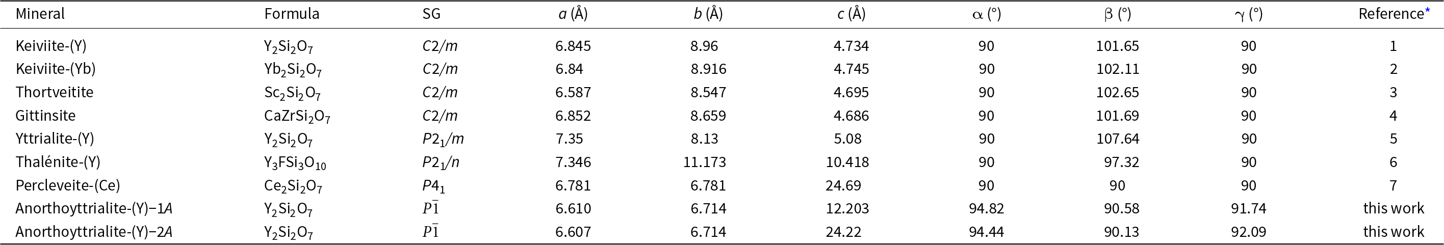
Disilicates of the rare earth elements (REE) occur in a wide range of crystal structures (Ito and Johnson, Reference Ito and Johnson1968; Felsche, Reference Felsche1970; Fleet and Liu, Reference Fleet and Liu2003). Most of these structure types contain [Si2O7]6– anions in various packing schemes. One structure type though, type B (Felsche, Reference Felsche1972; Fleet and Liu, Reference Fleet and Liu2003; Kahlenberg et al., Reference Kahlenberg, Wertl, Többens, Kaindl, Schuster and Schottenberger2008), contains linear trisilicate anions [Si3O10]8– along with isolated [SiO4]4– tetrahedra. This phase is also often referred to as the α-phase of the respective REE disilicate (Ito and Johnson, Reference Ito and Johnson1968; Kahlenberg et al., Reference Kahlenberg, Wertl, Többens, Kaindl, Schuster and Schottenberger2008) and synthetic compounds have been reported for a large variety of REE cation types of intermediate to small REE cation radius (Y, Eu, Gd, Tb, Dy, Ho, Er and Tm) in the experimental studies of Ito and Johnson (Reference Ito and Johnson1968), Felsche (Reference Felsche1970), Fleet and Liu (Reference Fleet and Liu2003) and Hartenbach et al. (Reference Hartenbach, Lissner and Schleid2003). The new mineral anorthoyttrialite-(Y) represents the first natural observation of this structure type. The composition of anorthoyttrialite-(Y) ideally is Y4(SiO4)(Si3O10), but as is the case in the holotype material, Y is partially substituted by varying amounts of other cations, of the lanthanides (Ln) in particular. Known minerals of similar composition comprise keiviite-(Y), Y2Si2O7, keiviite-(Yb), Yb2Si2O7, thortveitite, Sc2Si2O7, yttrialite-(Y), Y2Si2O7 and percleveite-(Ce), (Ce, La, Nd)2Si2O7 (Table 1). The crystal structure of anorthoyttrialite-(Y) is topologically different from those of yttrialite-(Y) and keiviite-(Y), as both structures contain [Si2O7]6– anions. However, the exact definition of yttrialite-(Y) is rather uncertain, due to its generally metamict state.
Minerals similar to anorthoyttrialite-(Y)

* References: 1: Voloshin et al. (Reference Voloshin, Pakhomovsky and Tyusheva1985); 2: Voloshin et al. (Reference Voloshin, Pakhomovsky and Tyusheva1983); 3: Bianchi et al. (Reference Bianchi, Pilati, Diella, Gramaccioli and Mannucci1988); 4: Roelofsen-Ahl and Peterson (Reference Roelofsen-Ahl and R.C1989); 5: Lyalina et al. (Reference Lyalina, Zozulya, Savchenko, Tarasov, Selivanova and Tarasova2014); 6: Škoda et al. (Reference Škoda, Plášil, Jonsson, Čopjaková, Langhof and Vašinová Galiová2015); 7: Holtstam et al. (Reference Holtstam, Norrestam and Anderson2003).
The holotype of yttrialite-(Y), Y2Si2O7, is a metamict mineral from Baringer Hill, Llano, Texas (Hidden and Mackintosh, Reference Hidden and Mackintosh1889). The type locality has been submerged under Lake Buchanan since 1939. Yttrialite-(Y) from this and other localities invariably contains ThO2 as a major constituent. According to some authors, Th may be an essential component of yttrialite, as it requires 13 wt.% ThO2 to be synthesised (Bondar and Toropov, Reference Bondar and Toropov1967). ThO2 contents reported for the yttrialites studied by Lyalina et al. (Reference Lyalina, Zozulya, Savchenko, Tarasov, Selivanova and Tarasova2014) range between 12.44 and 15.71 wt.%, yielding a Th content of ∼0.25 atoms per formula unit (apfu). Support for the essential Th component of yttrialite can also be derived from a study of yttrialite formed as a recrystallisation product of zircon from New Caledonia (Spandler et al., Reference Spandler, Hermann and Rubatto2004), where the host material as well as the other inclusions (thortveitite and xenotime) contain little or no ThO2, but the yttrialite inclusion contains 13.79 wt.% or 0.22 Th pfu. Yttrialite-(Y) with smaller ThO2 content of 6.97 wt.% has been reported by Nilssen (Reference Nilssen1971) from Ivedal in southern Norway, who also pointed out that the substitution of Th4+ for REE3+ is not charge neutral and requires a coupled substitution of divalent cations. Large Th-concentrations should therefore be accompanied by equally large concentrations of divalent cations such as Mg2+, Fe2+, Mn2+ or Ca2+ in yttrialite-(Y).
The colour of yttrialite is reported as olive–green, brown or black (Hidden and Macintosh, Reference Hidden and Mackintosh1889, Ewing and Ehlmann, Reference Ewing and Ehlmann1973) or dark red (Nilssen, Reference Nilssen1971), with vitreous or greasy lustre. According to Ito and Johnson (Reference Ito and Johnson1968), natural metamict yttrialite recrystallises above 1200°C to the α-form of Y2Si2O7, i.e. the B-type structure of anorthoyttrialite-(Y). It melts at ∼1450°C. Ewing and Ehlmann (Reference Ewing and Ehlmann1973) observed recrystallisation of yttrialite at 920°C by differential thermal analysis. According to these authors yttrialite-(Y) recrystallised at temperatures of 1000°C yields a so-called ‘low’ form, often described as γ-Y2Si2O7, which differs from anorthoyttrialite-(Y), but was deemed to be metastable by Ito and Johnson (Reference Ito and Johnson1968). Yttrialite-(Y) is usually defined with respect to the monoclinic low-yttrialite obtained by recrystallisation at temperatures between 700 and 1000°C (Nilssen, Reference Nilssen1971; Lyalina et al., Reference Lyalina, Zozulya, Savchenko, Tarasov, Selivanova and Tarasova2014), as this is considered to be the first crystalline phase to form. The unit-cell parameters in Table 1 are those given by Lyalina et al. (Reference Lyalina, Zozulya, Savchenko, Tarasov, Selivanova and Tarasova2014), obtained after annealing yttrialite from the Kola peninsula, Russia, at 900°C for one hour. Similar monoclinic unit-cell parameters (in a transformed unit cell setting with respect to that given in Table 1) are also given for entry 14180 of the American Mineralogist Crystal Structure Database (cf. Batalieva and Pyatenko, Reference Batalieva and Pyatenko1972, ICSD entry 28004). Synthetic analogues of yttrialite-(Y) have also been reported by Becerro et al. (Reference Becerro, Naranjo, Perdigón and Trillo2003), Hartenbach et al. (Reference Hartenbach, Meier and Schleid2006) and by Heward et al. (Reference Heward, Sarrafi-Nour and Gao2009).
Thalénite-(Y) (Table 1) is another rare earth mineral that has been associated with the composition Y2Si2O7 (Nagashima and Kato, Reference Nagashima and Kato1966). Its ideal composition is in fact Y3Si3O10F, but if essential fluorine content is overlooked and no crystallographic information is available, it may be mistaken for yttrialite-(Y). The crystal structure of thalénite-(Y) (Škoda et al., Reference Škoda, Plášil, Jonsson, Čopjaková, Langhof and Vašinová Galiová2015) is fundamentally different from anorthoyttrialite-(Y) or yttrialite-(Y). Just like anorthoyttrialite-(Y), thalénite-(Y) contains trisilicate groups, [Si3O10]8–. However, these groups are horseshoe shaped rather than linear.
The name anorthoyttrialite-(Y) (IMA 2022-135, mineral symbol Aytt-Y, Malcherek et al., Reference Malcherek, Schlüter and Husdal2023) is chosen for its compositional similarity with yttrialite-(Y) and its triclinic crystal structure, in accord with the “CNMNC guidelines for the nomenclature of polymorphs and polysomes” (Hatert et al., Reference Hatert, Mills, Pasero, Miyawaki and Bosi2023).
Type material (Catalogue No. no-007) is deposited at the Museum of Nature – Mineralogy, Hamburg, Germany.
Occurrence
Anorthoyttrialite-(Y) was discovered by one of the authors (TH) in 1999 in material collected a few years earlier from the Stetind pegmatite, Narvik, Nordland, Norway (68°10′15.20′′N 16°33′10.65′′E). The Stetind pegmatite is part of a group of ∼30 quartz–microcline granitic pegmatites of the NYF family, embedded in the Tysfjord granite, a series of ca. 1800 Ma Trans-Scandinavian Igneous Belt (TIB) granites exposed in a tectonic window in the Caledonian nappes in the northern part of Nordland (Müller et al., Reference Müller, Romer, Augland, Zhou, Rosing-Schow, Spratt and Husdal2022). Both the granites and pegmatites were deformed and partially recrystallised during the Caledonian orogeny around 400 Ma, under peak metamorphic conditions of ∼12 kbar and 730–750°C (Zhou et al., Reference Zhou, Müller, Augland, Kristoffersen and Erambert2022). The recrystallisation of primary pegmatite parageneses, along with the formation of small amazonite pegmatites from anatectic melts, produced a high mineral diversity, with a total of ∼250 different species identified (Husdal, Reference Husdal2008, Reference Husdal2019, Reference Husdal2020, Reference Husdal2021, Reference Husdal2023)
A characteristic paragenesis in these pegmatites is white to beige, granular aggregates of yttrian fluorite (= ‘yttrofluorite’ of Vogt, Reference Vogt1923) forming irregular or lens-shaped masses or bands that can be several metres in size. The fluorite typically has inclusions of various REE-minerals as mm-sized crystals, with the material from the Stetind pegmatite being particularly rich: nearly 40 different minerals, including the new species alnaperbøeite-(Ce), atelisite-(Y), bastnäsite-(Nd), cayalsite-(Y), perbøeite-(Ce), schlüterite-(Y) and stetindite-(Ce), have been identified. Anorthoyttrialite-(Y) was found in limited parts of the fluorite, as both sub- to euhedral crystals included in the fluorite aggregates, and as euhedral crystals on the walls of small cavities in the fluorite. Closely associated minerals are allanite-(Ce), alnaperbøeite-(Ce), bastnäsite-(Ce), hematite, hundholmenite-(Y), perbøeite-(Ce), rowlandite-(Y), schlüterite-(Y), synchysite-(Y), thalénite-(Y), törnebohmite-(Ce) and vyuntspakhkite-(Y).
Anorthoyttrialite-(Y) has also been found in very small amounts in cavities in yttrian fluorite from the related Hundholmen pegmatite (10 km to the west of the Stetind pegmatite), associated with hundholmenite-(Y), cayalsite-(Y), synchysite-(Y) and rowlandite-(Y).
Appearance and physical properties
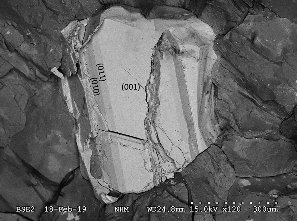
Anorthoyttrialite-(Y) occurs as tabular, translucent, colourless or white, yellow or brownish crystals of maximum dimension 2 mm (Fig. 1), embedded in massive yttrian fluorite (Fig. 2), and rarely as colourless prisms or very thin plates in small cavities in the fluorite. Observed forms are {001}, {100}, {010}, {011}, { $\bar 1$01} and {2 $\bar 1\bar 1$} for the 1A-holotype and co-type crystals. Crystal forms have been determined by goniometer based inspection and by crystal shape modelling using VESTA (Momma and Izumi, Reference Momma and Izumi2011). The crystallographic information file has been deposited with the Principal Editor of Mineralogical Magazine and is available as Supplementary material (see below). Anorthoyttrialite-(Y) is often partly or completely altered to white, powdery atelisite-(Y) or a closely related phase. Mohs hardness is 4 and its mean Vickers hardness, measured by micro-indentation with a load of 15g, is 255 kg/mm2 (range 238–290 kg/mm2). It has a white streak, adamantine lustre and is optically biaxial (–) with α = 1.705(1), β = 1.750(1), γ = 1.756(2) (at 589 nm) and 2Vcalc = 39.09°. It does neither show dispersion nor pleochroism. Anorthoyttrialite-(Y) is brittle and breaks unevenly, but has a (001) cleavage plane. The measured density, obtained using a pycnometer, is 5.1 g·cm–3, while its calculated density, obtained on the basis of the empirical formula and unit-cell volume from single-crystal X-ray diffraction data, is 5.24 g·cm–3. With the calculated density the compatibility index 1–(K P/K C) is only poor, with ±0.098. With the measured density it is fair ±0.074. This may indicate slight metamictisation of the mineral, with higher density resulting from the well crystallised fraction, as opposed to lower actual density of the defect rich crystal bulk.
Microphotograph of anorthoyttrialite-(Y)-1A (co-type crystal).
Scanning electron microscopy image of anorthoyttrialite-(Y)-1A (bright), embedded in fluorite (dark) (co-type crystal).

The a:b:c ratio calculated from single-crystal XRD unit-cell parameters is 0.985:1:1.818.
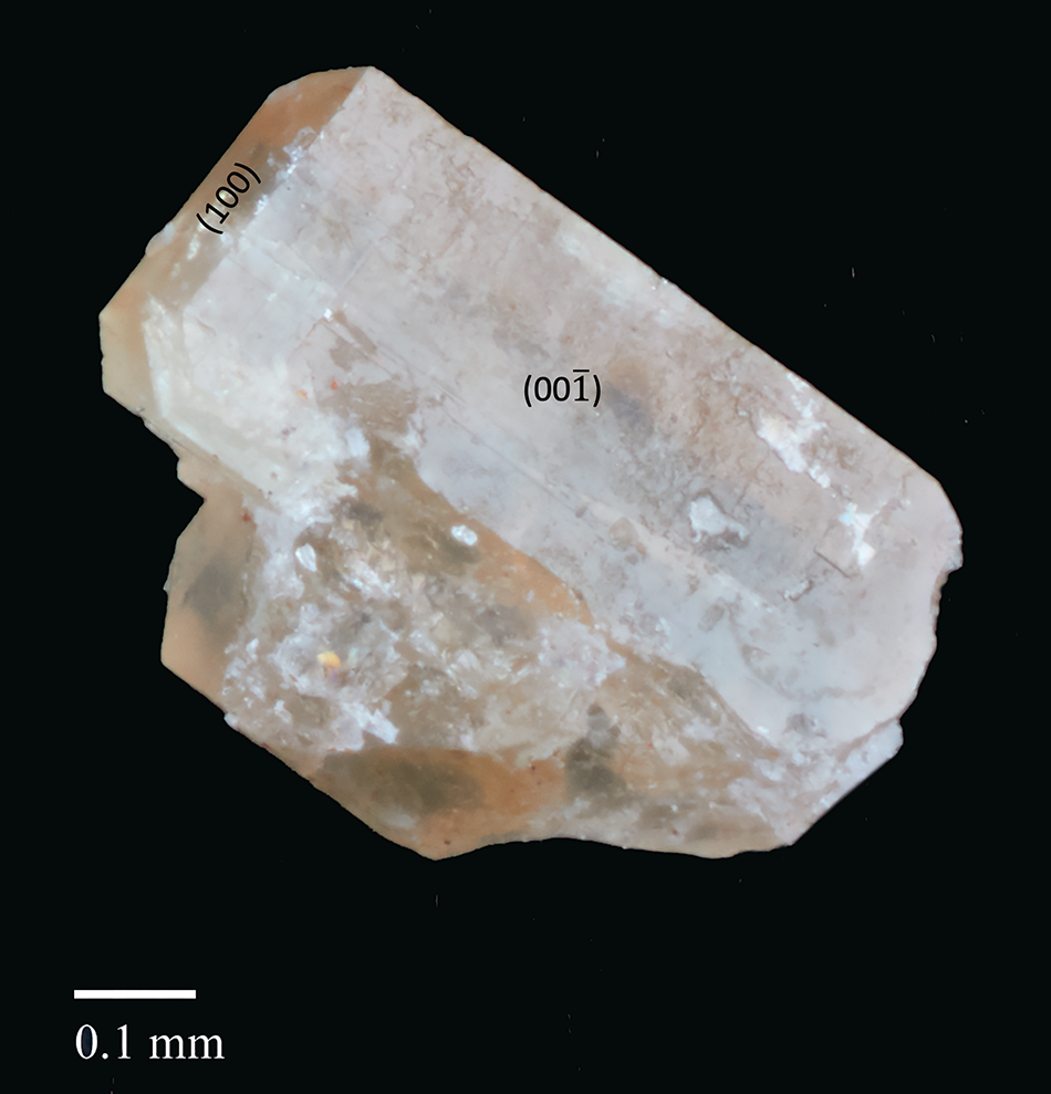
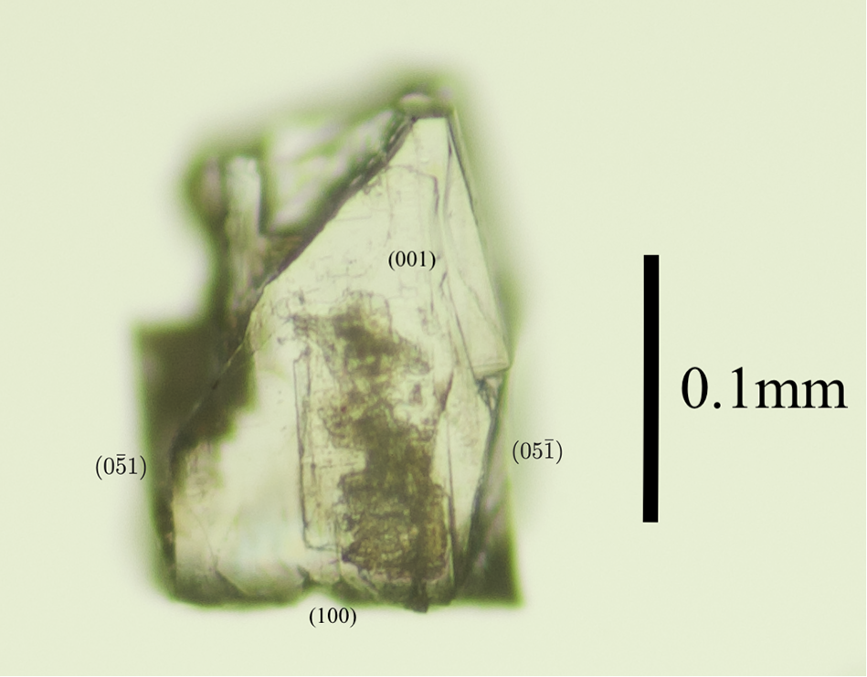
Among the associated minerals of anorthoyttrialite-(Y) was a singular prismatic, transparent, colourless and strongly birefringent crystal. Electron microprobe analysis and X-ray single-crystal diffraction have been performed on different fragments of this larger crystal (Fig. 3). The composition is very similar to anorthoyttrialite-(Y), except for minor fluorine content (Table 2). The refined total Ln content from X-ray diffraction, as represented by the Ho scattering factor, is 1.044 apfu compared to 1.199 apfu from microprobe analysis (see below). This crystal will be referred to as the 2A-cotype in the following.
Microphotograph of anorthoyttrialite-(Y)-2A in transmitted light.

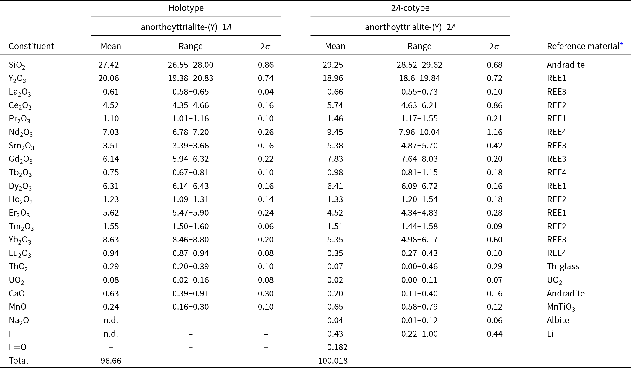
Chemical data (in wt.%) for the holotype anorthoyttrialite-(Y)-1A and the 2A-cotype, anorthoyttrialite-(Y)-2A

* Compositions of the standards (in wt.%). Andradite = Ca: 23.84, Fe: 21.89, Si: 16.36, Mg: 0.18, O: 37.73; MnTiO3 = Mn: 36.4226, Ti: 31.7566, O: 31.8209; REE1 = Si: 23.27, Al: 6.23, Ca: 13.43, Y: 3.97, Pr: 3.93, Dy: 4.02, Er: 3.97, O: 40.46; REE2 = Si: 23.53, Al: 6.3, Ca: 13.49, Ce: 3.93, Eu: 3.99, Ho: 3.92, Tm: 4.01, O: 40.47; REE3 = Si: 23.56, Al: 6.31, Ca: 13.8, La: 4.01, Sm: 3.82, Gd: 4., Yb: 4.03, O: 40.43; REE4 = Si: 24.76, Al: 6.66, Ca: 14.42, Nd: 3.89, Tb: 4., Lu: 3.97, O: 41.8; Th-glass = Si: 27.23, Al: 7.4, Ca: 15.76, Th: 5.18, O: 44.65; UO2 = U: 88.1501, O: 11.8499; Albite = Na: 8.52, Mg: 0.09, Al: 10.12, Si: 31.94, K: 0.18, Ca: 0.45, Fe: 0.05, O: 48.65; LiF = Li: 26.7533, F: 73.2467; and Pb-glass = Pb: 51.63, Si: 13.52, Al: 0.16, Fe: 0.05, Mg: 0.05, Zn: 11.2, K: 0.02, O: 22.36.
Chemical data
Electron microprobe analyses (EMPA) of anorthoyttrialite-(Y) have been carried out in wavelength dispersive (WDS) mode using a Cameca SX100 instrument. Acceleration voltage was 15 kV and beam current 40 nA, with a beam diameter of 1 μm. 11 spot analysis have been conducted on the holotype grain and 17 spot analysis on a fragment of the 2A-cotyp (Table 2).
The empirical formula, calculated on the basis of 14 anions, is:
(Y1.561La0.033Ce0.242Pr0.059Nd0.367Sm0.177Gd0.298Tb0.036Dy0.297Ho0.058Er0.258Tm0.071Yb0.385Lu0.041Ca0.099Mn0.029U0.003Th0.01)Σ4.024Si4.011O14.00 for the holotype and
(Y1.4La0.034Ce0.292Pr0.074Nd0.469Sm0.257Gd0.36Tb0.044Dy0.287Ho0.059Er0.197Tm0.065Yb0.227Lu0.015Ca0.03Mn0.076Th0.002U0.001Na0.011)Σ3.9Si4.059(O13.81F0.19)Σ14.00
for the 2A-cotype. The 2A-cotype structure apparently supports a slightly higher concentration of the larger, light REE Ce, Pr, Nd, Sm and Gd, while the smaller cations of Y, Er, Tm, Yb and Lu have lower concentrations than in the holotype structure. The rather low oxide sum of the holotype crystal is attributed to poor sample quality, indicated by numerous fine cracks and pores in the electron back-scattering image. This may be due to slight metamictisation and alteration of the sample. The 2A-cotype crystal fragment with its lower Th- and U-contents and ideal oxide sum did not show similar surface defects.
For the holotype material, the simplified formula is (Y, Ce, Nd, Sm, Gd, Dy, Er, Tm, Yb)4(SiO4)(Si3O10) and for the 2A-cotype with Z = 4 it is (Y, Ce, Pr, Nd, Sm, Gd, Dy, Er, Yb)4(SiO4) (Si3O10).
The ideal formula of anorthoyttrialite-(Y) is Y4(SiO4)(Si3O10), which requires SiO2 34.73 wt.%, Y2O3 65.27 wt.%, total 100%.
Anorthoyttrialite-(Y) does not react with concentrated HCl, H2SO4 nor HNO3 at room temperature.
Crystal structure
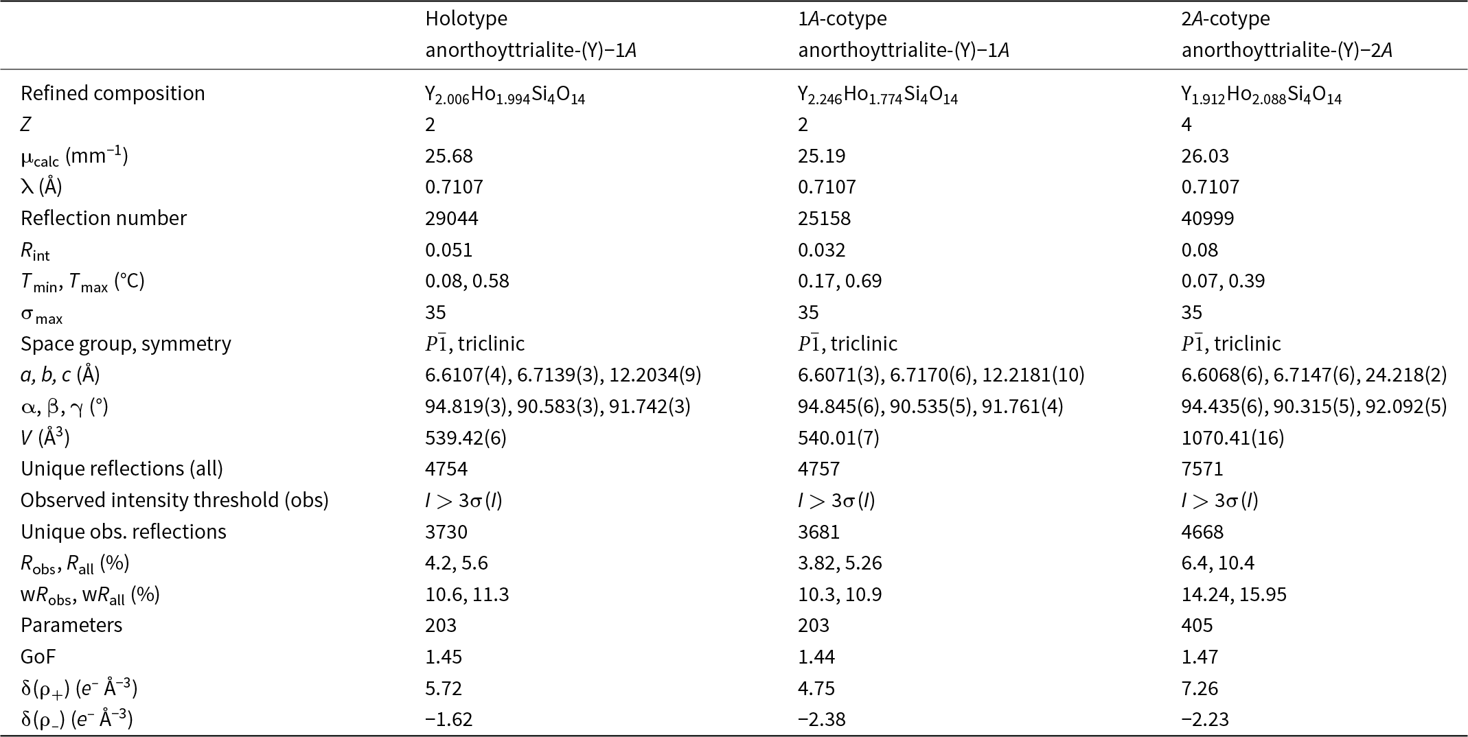
Single-crystal X-ray studies were carried out using a Nonius KappaCCD X-ray single crystal diffractometer with graphite monochromated MoKα radiation. CCD pixel data have been integrated and corrected using the Eval15 suite of programs (Schreuers et al., Reference Schreurs, Xian and Kroon-Batenburg2010). The structure of anorthoyttrialite-(Y) has been solved and refined using Superflip (Palatinus and Chapuis, Reference Palatinus and Chapuis2007) and Jana2006 (Petřìček et al., Reference Petřìček, Dušek and Palatinus2014) for both polytypes. Scattering factors of the neutral elements have been used. Crystal structure plots have been prepared using CrystalMaker X (Palmer, Reference Palmer2015). The holotype is a tabular, white crystal with dominant form {001}. The 1A-cotype is a colourless, needle shaped crystal with elongation direction of [6 $\bar 1$5], corresponding to the orientation of the [Si3O10]8– groups. The 2A-cotype crystal, anorthoyttrialite-(Y)-2A, consists of two slightly tilted domains. Non-overlapping diffraction data of the domain with the higher volume proportion have been used for structure refinement.
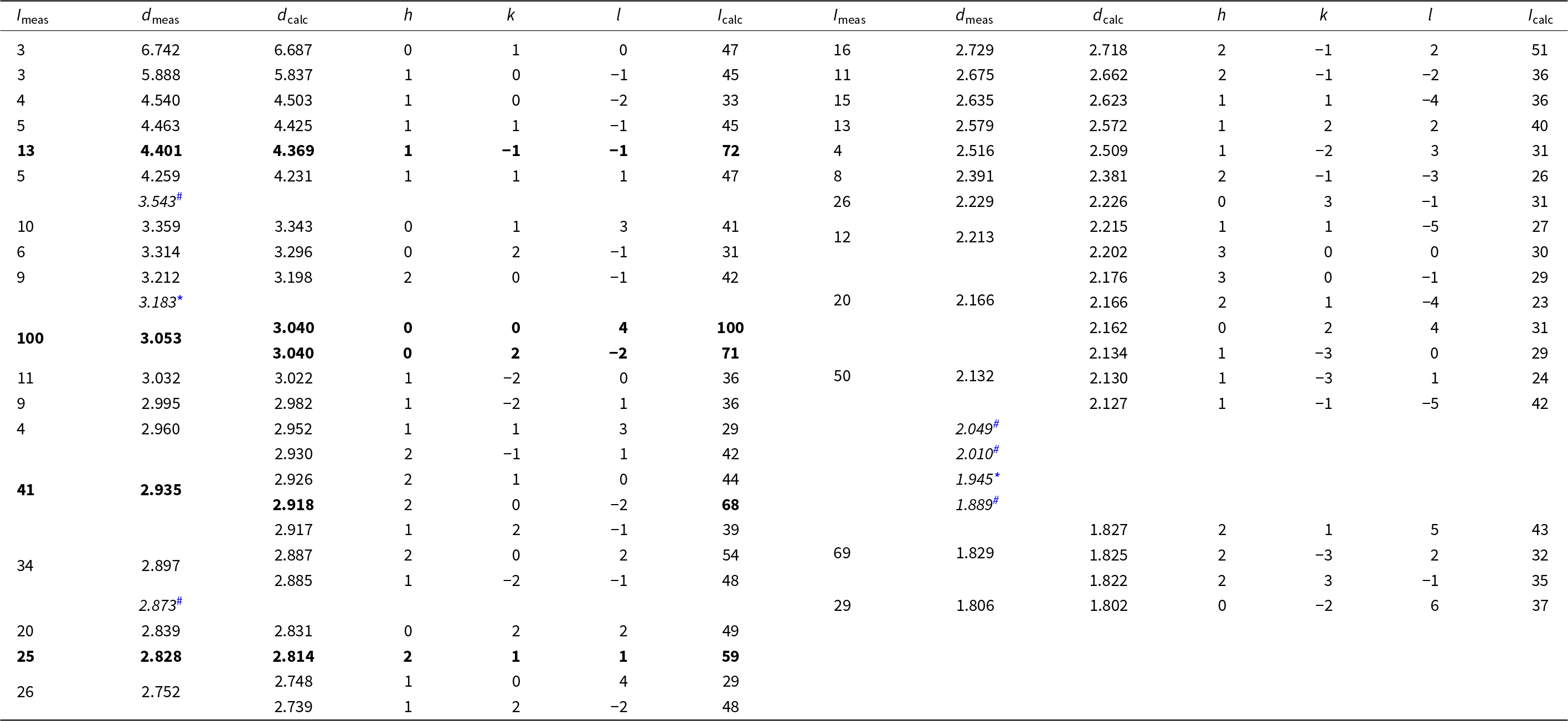
Powder X-ray diffraction data for anorthoyttrialite-(Y) were collected using a STOE StadiMP diffractometer in Bragg-Brentano geometry, equipped with an asymmetric curved Ge(111) monochromator producing CuKα1 radiation, λ = 1.5406 Å. Scattered radiation was detected using a linear PSD. Some powdered sample material containing yttrofluorite (7 wt.%) and bastnäsite (3 wt.%) impurities was dispersed on a zero diffraction Si-wafer. Table 3 provides the observed and calculated d-spacings and intensities measured for anorthoyttrialite-(Y)-1A, with calculated values obtained from the single-crystal data of the holotype using Jana2006. Unit cell parameters obtained by Rietveld refinement using the GSAS/EXPGUI program (Toby, Reference Toby2001) with fixed atomic coordinates are: a = 6.620(2), b = 6.719(2), c = 12.219(2) Å, α = 94.83(3), β = 90.70(3), γ = 91.73(2)° and V = 541.2(3) Å3.
Powder diffraction data (d, Å, I, %) for anorthoyttrialite-(Y)-1A

* Note: Intensities < 3%, maxima with d <1.8 Å and peaks hidden by impurities fluorite (*) and bastnäsite-(Ce) (#) [d-values indicated in italics] have been omitted. The strongest lines are given in bold.
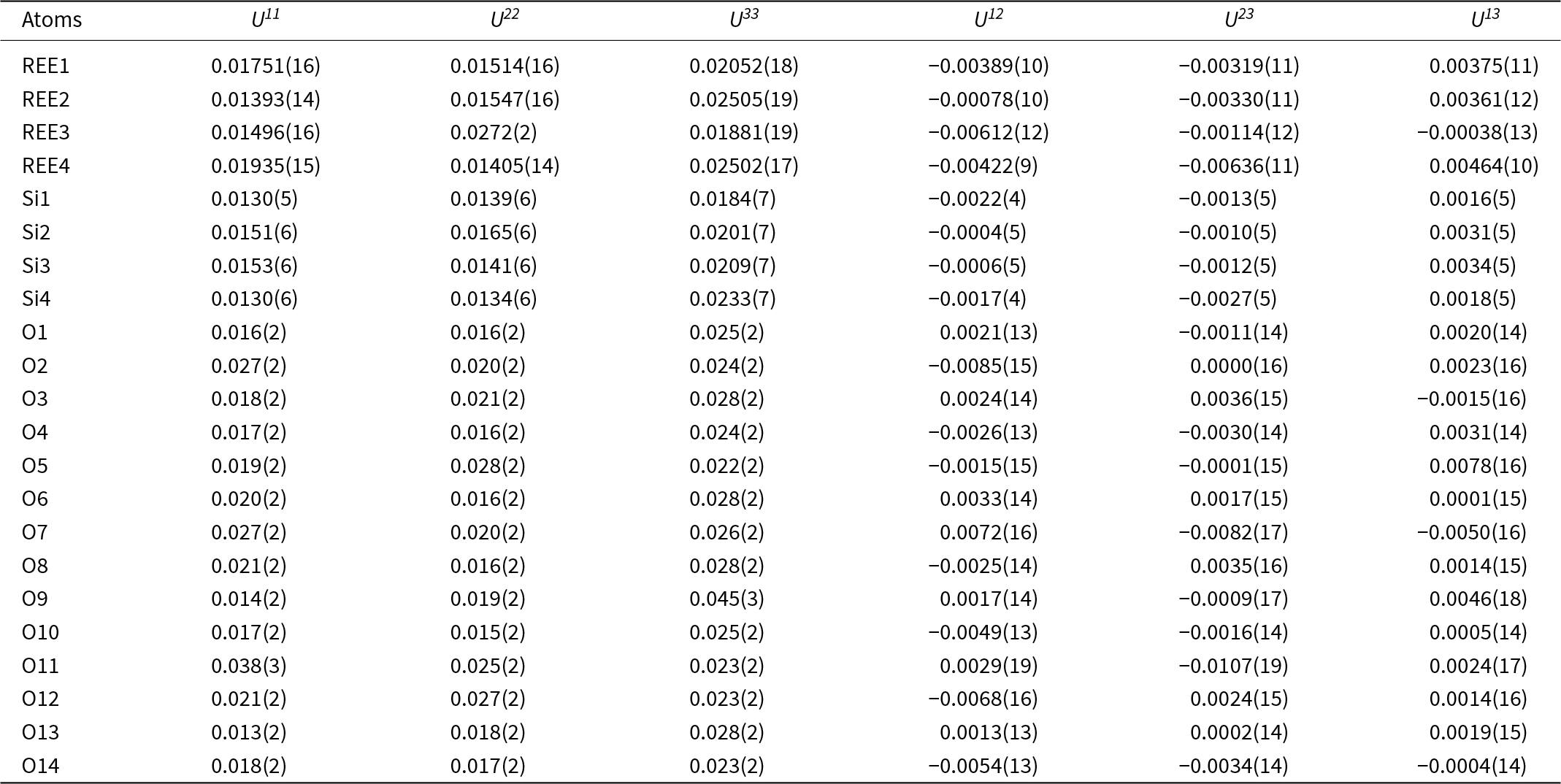
Structure refinement of two anorthoyttrialite-(Y)-1A single crystals (holotype and 1A-cotype) was conducted using a simplified model of REE occupancy at the sites REE1 to REE4. X-ray scattering at these sites was modelled using scattering functions of Y and Ho, with the latter representing an average scattering function of the Ln elements occupying these four sites and the former also modelling the scattering by the lighter elements Ca and Mn (Table 2). The refined total Y contents (Table 4) are larger than Y+Ca+Mn = 1.69, while the refined total ‘Ho’ contents are smaller than the sum of Ln+U+Th = 2.31 from the microprobe analysis. The discrepancy is probably caused by compositional variations of individual crystals used for microprobe analysis and X-ray diffraction, as indicated by the different total occupancies in the two crystals studied by single-crystal XRD. Refined site occupancies, positional parameters and equivalent isotropic displacement parameters are in Table 5 and anisotropic displacement parameters in Table 6. As the atom coordinates of the two crystals vary to a lesser degree, only the holotype data is given.
Crystal data and refinement details for anorthoyttrialite-(Y)
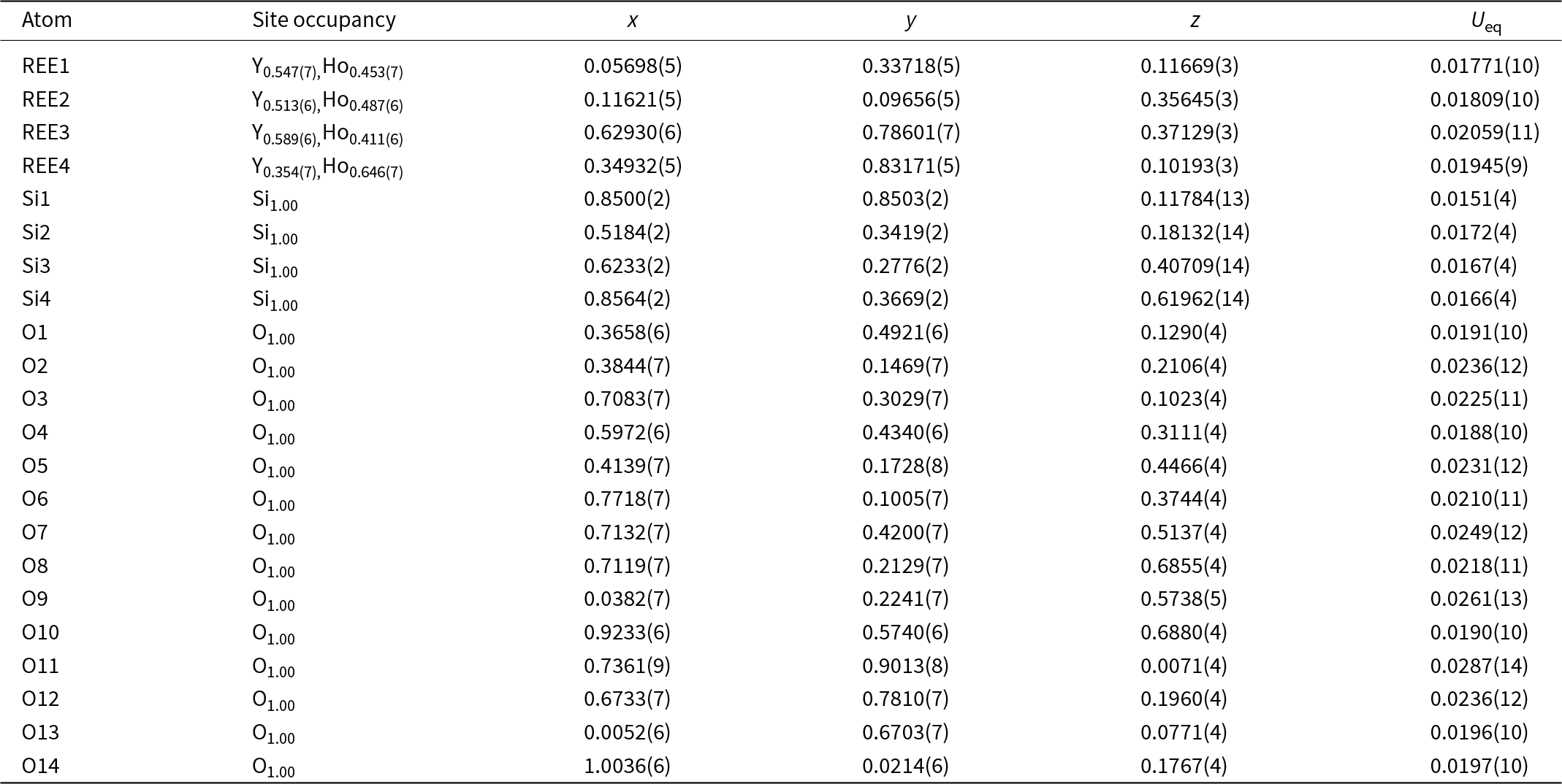
Refined site occupancies, positional parameters and equivalent isotropic displacement parameter U eq (Å2) for holotype anorthoyttrialite-(Y)-1A

Anisotropic displacement parameters (Å2) for holotype anorthoyttrialite-(Y)
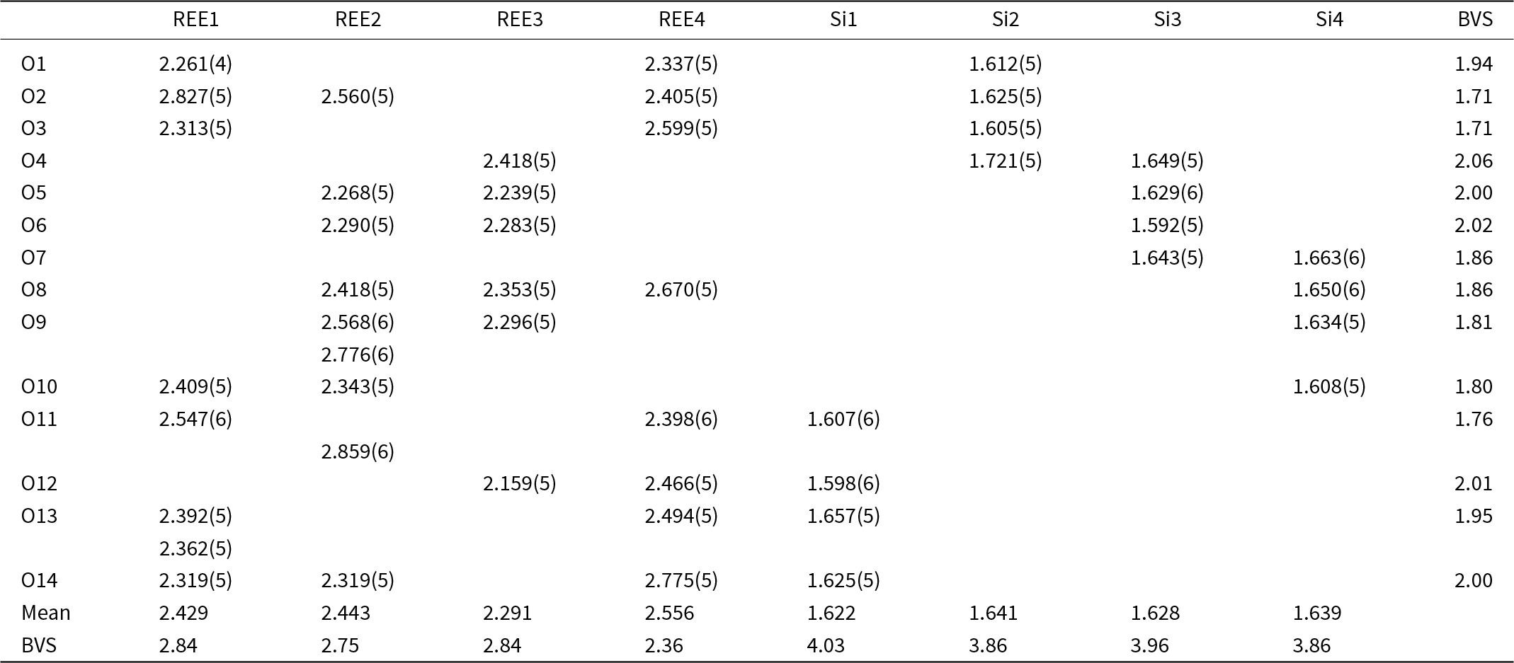
The REE3 site is coordinated by six oxygen atoms, forming a distorted octahedron. This is also the site with the highest refined Y occupancy and correspondingly that with the smallest mean REE–O distance (Table 7). REE1 and REE2 are eight-fold coordinated. The nine-fold coordinated site REE4 forms the largest of the REEOx polyhedra (Table 7, Fig. 4) and it also hosts the largest proportion of lanthanide cations, as shown by the refined Ho occupancy (Table 5). Tables 6 and 7 also lists the bond valence sums of cations and anions, calculated for the ideal formula, i.e. with all REE sites fully occupied by Y. This yields slightly to moderately underbonded REE, especially for REE4, as the partial occupancy by larger Ln-cations is ignored. Some of the oxygen anions (O2, O3, O11) appear underbonded too, again because these anions belong to the REE4 coordination sphere. Bond valence parameters for Si–O and Y–O bonds have been taken from Gagné and Hawthorne (Reference Gagné and F.C2015).
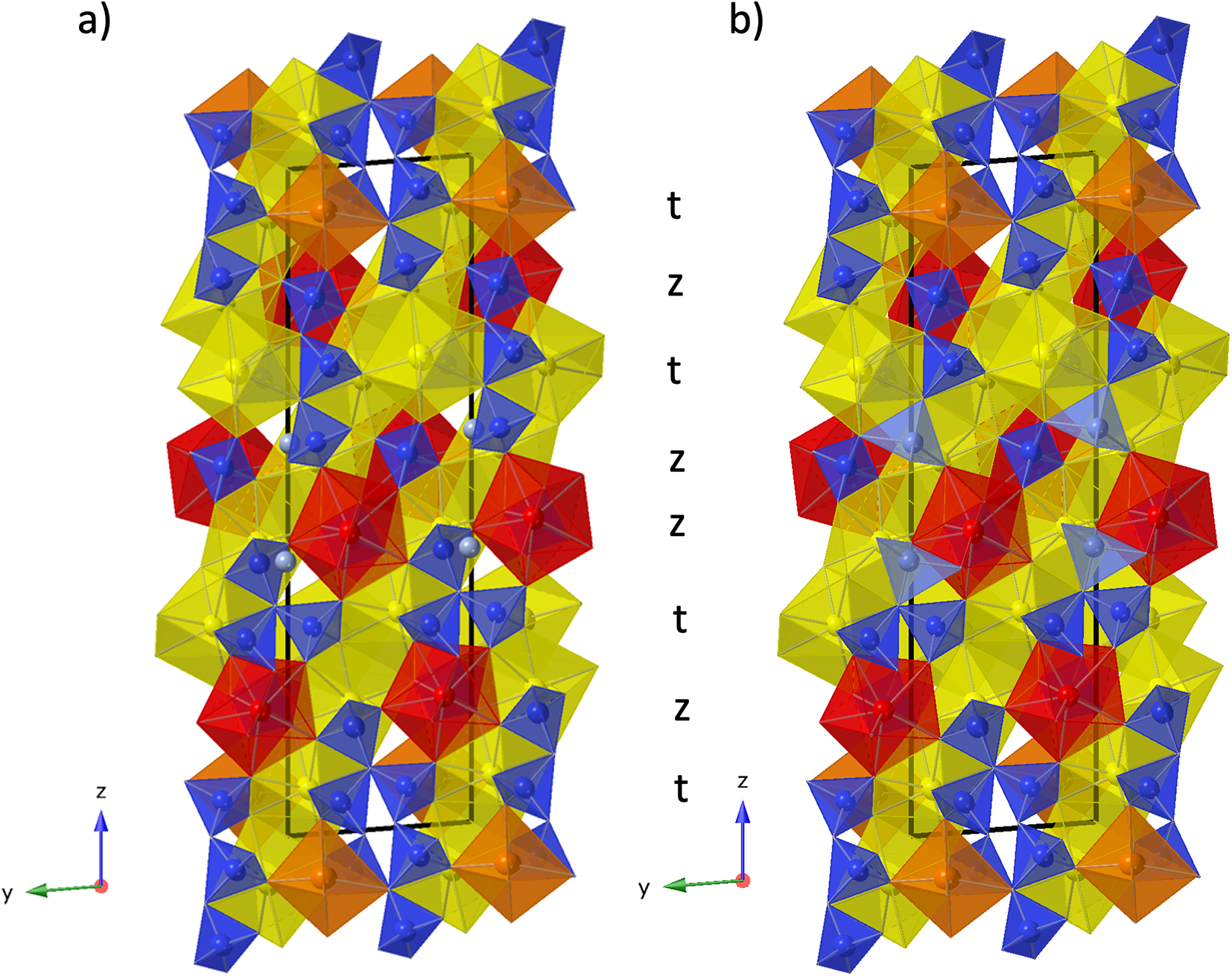
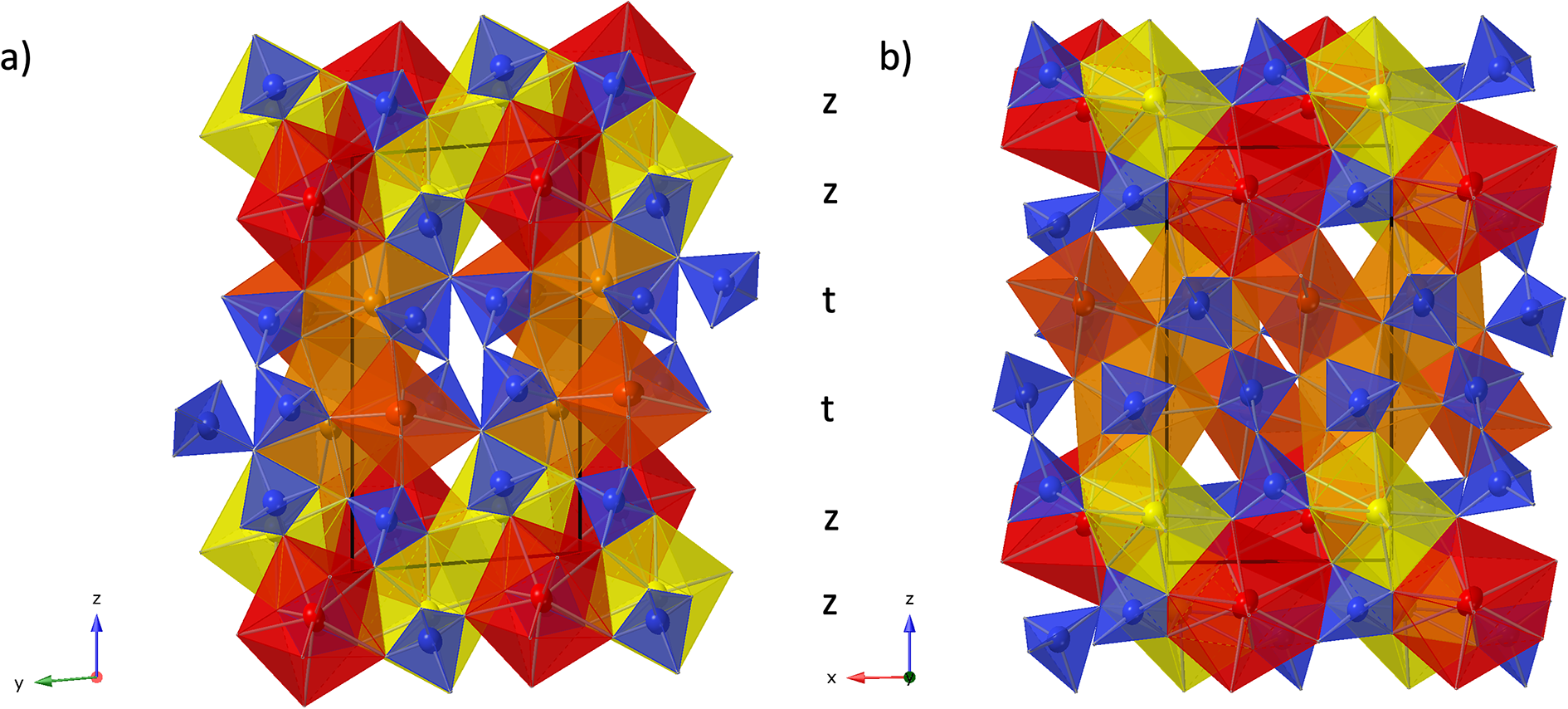
Crystal structure of anorthoyttrialite-(Y)-1A in projection along [100] (a) and [010] (b) Letters t and z indicate the layer sequence. SiO4 tetrahedra are shown in blue colour. Yellow, bright orange, dark orange and red colours indicate the oxygen polyhedra coordinating REE1 to REE4, respectively.

Selected interatomic distances (Å) and bond valence sums (BVS) for holotype anorthoyttrialite-(Y)-1A
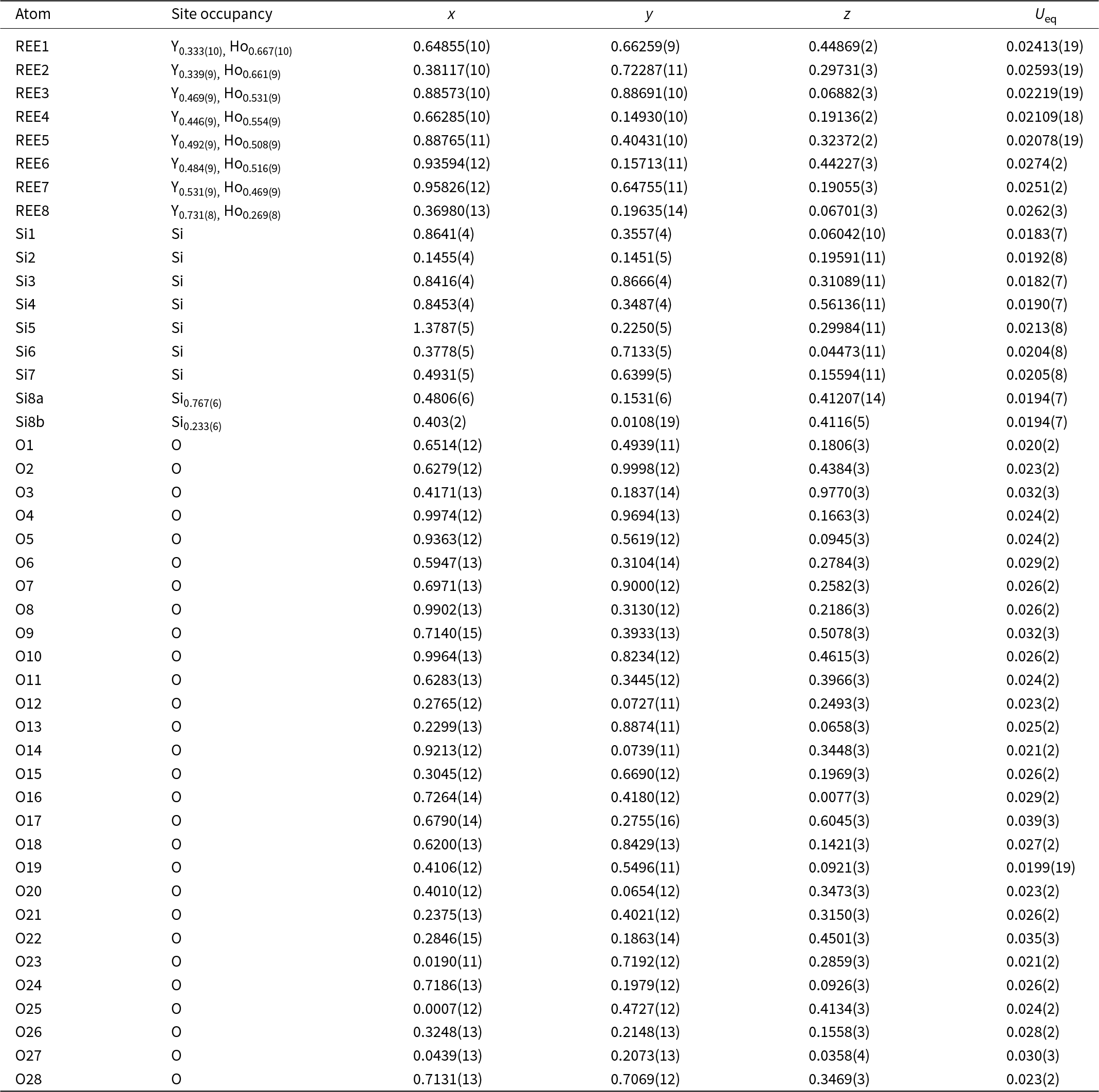
Structure refinement of the 2A-polytype crystal fragment (the 2A-cotype), pictured in Fig. 5, was conducted using the same REE occupancy model as for the holotype. The total refined Y-content is 1.91 (Table 4), which again is higher than the sum of Y, Ca and Mn from EMPA, but confirms the trend of depleted concentrations of smaller cations in the 2A-polytype structure. In the doubled unit cell of the 2A-polytype there are eight REE sites, of which REE1 is 9-coordinated with a mean REE-O distance of 2.536 Å. REE2, REE3, REE4, REE5 and REE6 are 8-coordinated with a mean distance of 2.512, 2.44, 2.428, 2.413 and 2.418 Å, respectively, while REE7 and REE8 have a distorted octahedral coordination with mean bond distances of 2.324 and 2.28 Å respectively. The largest site, REE1, refines with the smallest Y-occupancy of just ⅓, while the two smallest, 6-fold coordinated sites REE7 and REE8 yield the highest Y-occupancy of 0.53 and 0.73, respectively (Table 8).
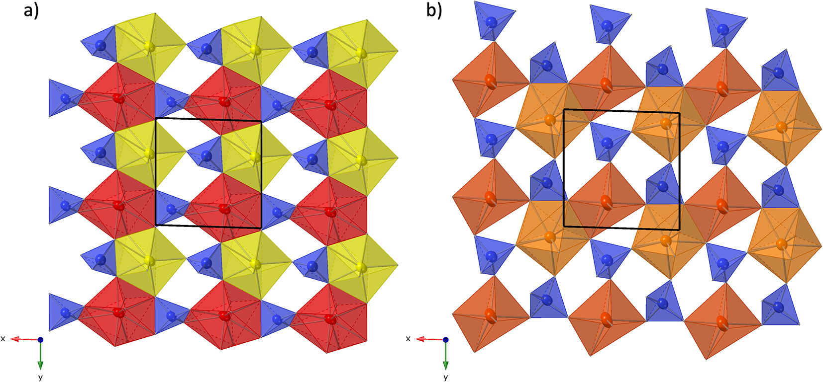
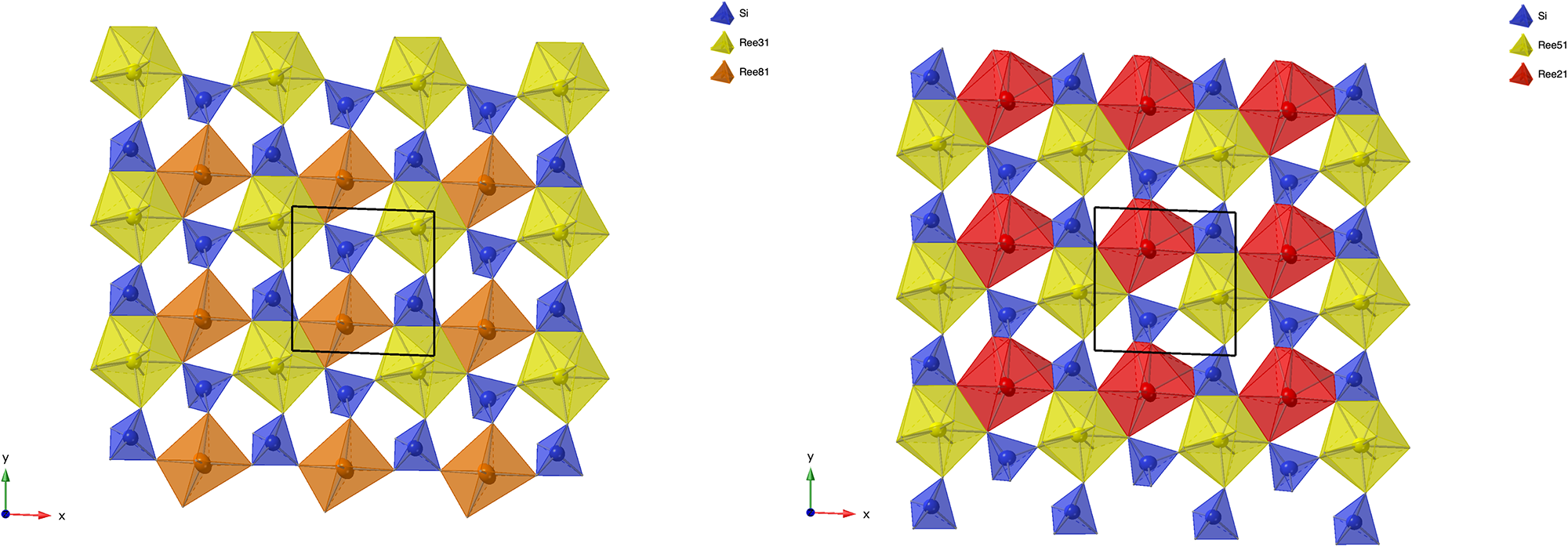
(a) Crystal structure of anorthoyttrialite-(Y)-2A in projection along [100]. Letters t and z indicate the layer sequence. SiO4 tetrahedra are shown in blue colour. Orange, yellow, and red colours indicate REE-oxygen polyhedra with 6-fold, 8-fold and 9-fold coordination, respectively. Disordered Si8b-atoms are shown in light blue. (b) Same image as in (a), showing the Si8b atoms in distorted tetrahedral coordination and omitting Si8a.
Refined site occupancies, positional parameters and equivalent isotropic displacement U eq (Å2) for anorthoyttrialite-(Y)-2A

Eight different Si-sites exist in the 2A-polytype structure (Fig. 5a). In the initial structure refinement, Si8 had unusually large anisotropic displacement parameters U 11 and U 22, resulting in U eq being significantly above the average displacement parameters of the other seven Si atoms. A prominent difference-Fourier density maximum was located at 1.06 Å distance to Si8. This indicated that Si8 is disordered over two positions to either side of the tetrahedral face formed by O2, O20 and O22. Appropriately constrained refinement of these two positions with isotropic displacement parameters, yielded Si8a with 77% and Si8b with 23% site occupancy. Distorted tetrahedral coordination of Si8b involves O17, which is at a rather large distance of 1.99 Å to Si8b. However, disorder of O17 itself may be indicated by its relatively large displacement factor. Site splitting of O17 might provide for a more realistic bond distance to Si8b, but could not be resolved with the present diffraction data. The disorder across two tetrahedral positions indicates that a 23% fraction of the anorthoyttrialite-(Y)-2A crystal structure contains curved chains of four corner-sharing SiO4-tetrahedra, as pictured in Fig. 5b. The small F-content determined for the anorthoyttrialite-(Y)-2A crystal (0.19 apfu) could be the cause for the disorder, as it approximately equals the concentration of displaced Si8b atoms. This would suggest that F partially substitutes for O11, which is the apical corner atom of the Si8aO4 tetrahedron and 2.7 Å distant from Si8b. O11 is otherwise bonded to REE1 (2.394 Å), REE5 (2.511 Å) and REE6 (2.705 Å).
Results and discussion
Crystal structure and polytypism of anorthoyttrialite-(Y)
Anorthoyttrialite-(Y)-1A is isostructural with the B-type structure of the synthetically known rare earth disilicates. Using the Compstru program (De la Flor et al., Reference De la Flor, Orobengoa, Tasci, Perez–Mato and Aroyo2016), the maximum distance with respect to Gd2Si2O7 (Fleet and Liu, Reference Fleet and Liu2003) is obtained as 0.1817 Å for O11. Comparison with the crystal structure of Y2Si2O7 (Kahlenberg et al., Reference Kahlenberg, Wertl, Többens, Kaindl, Schuster and Schottenberger2008), after unit cell standardisation with a′ = a, b′ = –b and c′ = –c (see ICSD entry 173383), yields a slightly larger maximum deviation of 0.2395 Å for O11, with most of the other atoms deviating by <0.1 Å. O11 is a 4-coordinated anion, shared between REE1, two REE4 and Si1. REE4 is also the cation with the largest deviation from the equivalent positions in Gd2Si2O7 (0.1017 Å) and in Y2Si2O7 (0.1288 Å). In both cases, the largest relative displacement component of O11 and REE4 is parallel to [100], but in a mutually opposite direction for anion and cation. The deviations can be attributed to the mixed occupancy of the REE sites in anorthoyttrialite-(Y)-1A, which are occupied by just one cation species in the synthetic compounds.
The crystal structure of both polytypes can be understood as resulting from a small number of layers composed of SiO4 tetrahedra and YOx-polyhedra. These layers are stacked along [001], sharing their outer oxygen corner atoms with neighbouring layers. The first such layer is shown in Fig. 6a. It consists of parallel chains of edge and face sharing REEO8 and REEO9-polyhedra, interconnected by SiO4 tetrahedra. These tetrahedra either share both opposite edges with two REEO9-polyhedra, in which case they constitute the isolated SiO4-tetrahedra of the B-type structure, or they share one edge and one corner with two REEO8, thus having one remaining corner oxygen atom free to share with SiO4 tetrahedra in neighbouring layers, i.e. for participation in the linear trisilicate groups. These latter SiO4 tetrahedra are therefore tilted out of the layer, with the z-coordinate of the central Si differing from those of the other cations in the layer. The free corner atoms all point towards the same side of the layer. As there is some topological resemblance to the (010) layer of the zircon structure, we will designate this type of layer the zircon or z-layer.
Structural layers parallel to (001), composing the anorthoyttrialite-(Y) structure. (a) zircon-layer (z-layer) and (b) thortveitite-layer (t-layer). Colour scheme as in Fig. 4.

The second type of layer is shown in Fig. 6b, in which the remaining REEO8 and REEO6 polyhedra form edge-sharing pairs. The dimers share corners with neighbouring dimers and are otherwise interconnected by SiO4 tetrahedra that share corners or edges with the REEOx polyhedra. One corner of each SiO4 remains unbonded and thus free to share corners with SiO4 in adjacent layers. All free corner oxygens again point to the same side of the layer. Because these layers are topologically similar to the ( $\bar 201$) layers of the thortveitite structure, we will designate them as thortveitite or t-layers.
In simplified terms, the anorthoyttrialite-(Y)-1A structure is formed by a repeating sequence of four layers, zzttzztt…. (Fig. 4). The longer, 8-layer sequence tztzztzttztzztzt… gives rise to the anorthoyttrialite-(Y)-2A structure (Fig. 5). As the doubled cell of the 2A-cotype structure hosts eight different REE sites (Table 8), their coordination varies more widely than in the holotype structure. Also, some of the z-layers differ from the unmodified z-layers by disorder of half of the Si atoms. In general, the layer notations t and z describe the relative configuration of the Si and REE cations. Oxygen coordination of the REE as well as orientation of the SiO4 tetrahedra and rotation or translation of the layers may vary as demonstrated in Fig. 7.
Two t-layers composing the anorthoyttrialite-(Y)-2A polytype structure. The right-hand layer is shifted by ½ along [010] with respect to the left-hand layer and the coordination numbers of one half of the REE cations differ (6-ccordinated, orange and 8-coordinated, red colour).

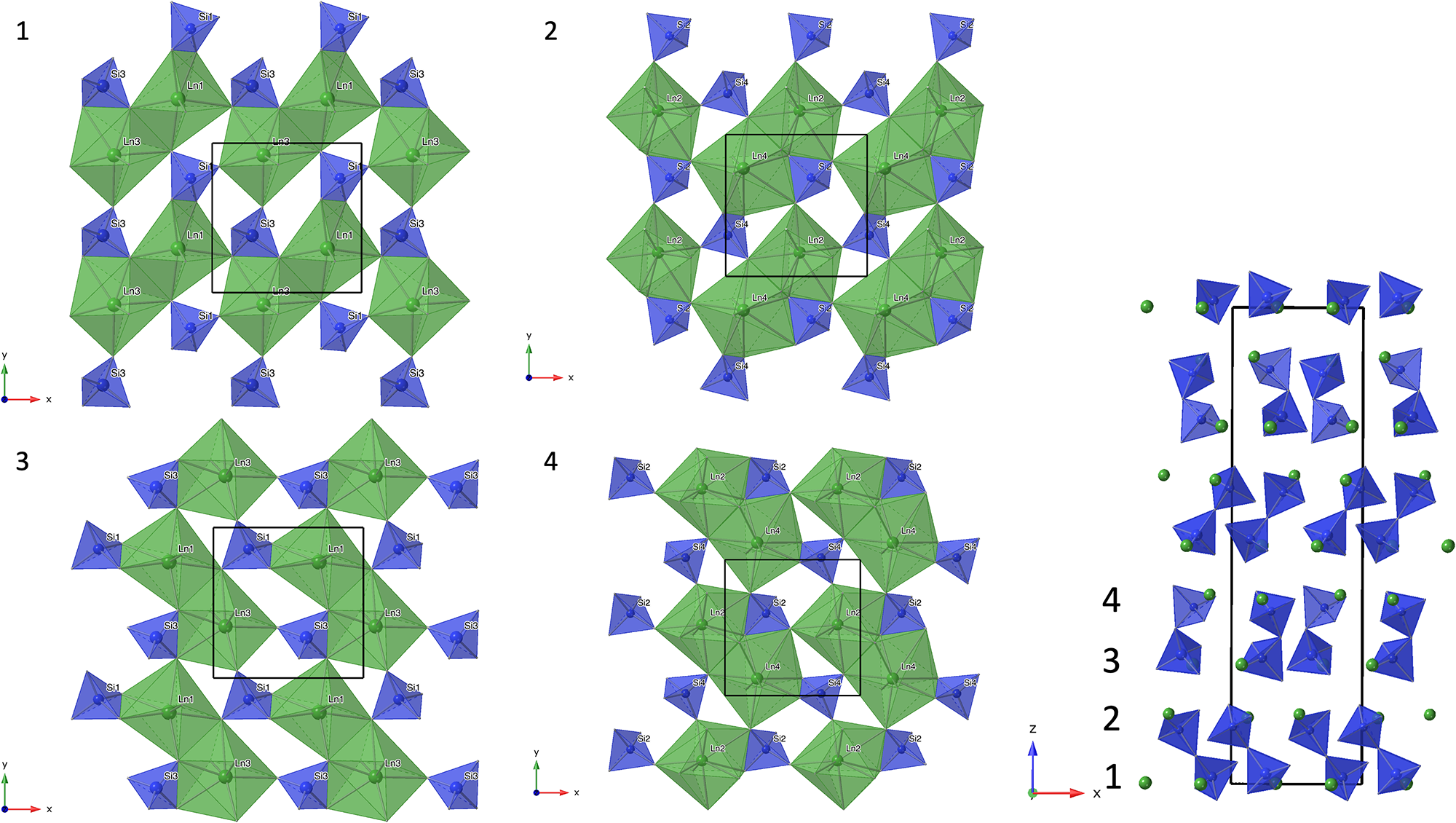
Other REE disilicate structures can be related to the same layer topology. The crystal structure of percleveite-(Ce) is isostructural with La2Si2O7 (Holtstam et al., Reference Holtstam, Norrestam and Anderson2003), which in turn is of the β-Ca2P2O7 structure type (Webb, Reference Webb1966). In the nomenclature of Felsche (Reference Felsche1970) this is the A-type structure. The tetragonal structure of these compounds can be constructed by stacking only t-layers, when applying appropriate rotations to the eight individual layers that make up one unit cell. The first four such layers are shown in Fig. 8, in the order of increasing z-coordinate. With respect to layer 1, layer 3 is rotated 90° anticlockwise, while layer 4 is rotated 90° anticlockwise with respect to layer 2. Layer 1 and 2 as well as layer 3 and 4 are related by 180° rotation, when differences in the coordination numbers of the Ln-sites and related, different out-of-plane tilting of the SiO4-tetrahedra are ignored. As anorthoyttrialite-(Y)-2A is equally built from a sequence comprising eight layers, it has unit cell dimensions that are very similar to percleveite-(Ce) (Table 1). Its lower symmetry with respect to percleveite-(Ce) results from the replacement of four of the t-layers by an equal number of z-layers.
The first four, sequentially numbered t-layers in the percleveite-(Ce) crystal structure. The right hand side diagram indicates the position of the four layers in the tetragonal unit cell and the formation of Si2O7 groups between the layers. Structure data and site labels taken from Holtstam et al. (Reference Holtstam, Norrestam and Anderson2003).
The keiviite-(Y) or keiviite-(Yb) crystal structure, adopting the thortveitite structure type, is obviously related to stacking of t-layers. However, in order to form this crystal structure, the position of the oxygen anions of the thortveitite layers as defined above has to be altered, so that the free corners of the SiO4-tetrahedra point to alternating sides of the layers, enabling them to form sorosilicate groups with the tetrahedra in both adjacent layers.
Relation to yttrialite-(Y)
A vitreous, black to reddish-brown, metamict amorphous mineral, previously identified as yttrialite-(Y) based on the powder XRD pattern of annealed material (Husdal, Reference Husdal2008), occurs in the fluorite from Stetind, sometimes closely associated with anorthoyttrialite-(Y). An overview of EMPA of three such samples is given in Table 9. All samples are X-ray amorphous, with the exception of fluorite inclusions in Y9, but differ in colour intensity. Y9 and Y10 have dark brown and black colour respectively, while Y11 is colourless to light brown. In comparison to anorthoyttrialite-(Y), the metamict mineral is characterised not only by its significant Th-content, but also by its related Ca-content, while equally charge balancing Fe2+ that has been found in other yttrialites (Ewing and Ehlmann, Reference Ewing and Ehlmann1973) is absent.
Composition of three samples of a metamict Y-silicate from Stetind in wt.%. For compositions of reference materials see Table 2
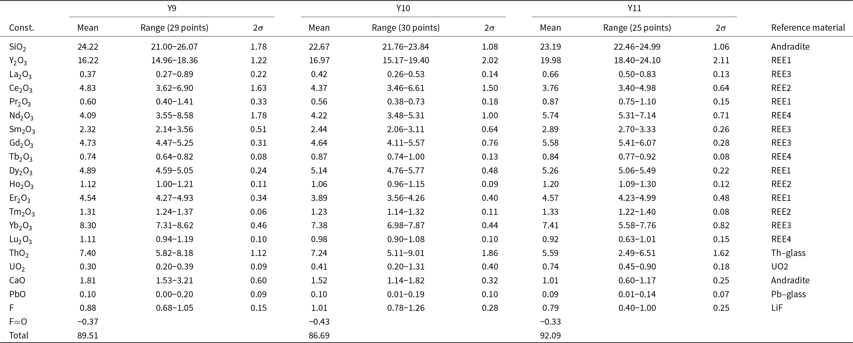
Oxide sums are rather low for all analyses (see Table 9), but no other elements could be detected. Disregarding possible water content, the empirical formulas normalised to 14 anions are (Ln = lanthanides):
Y9: (Y1.38Ln 2.05Th0.27Ca0.31)Σ4.01Si3.88O13.55F0.45
Y10: (Y1.5Ln 2.05Th0.27U0.02Ca0.27)Σ4.11Si3.78O13.47F0.53
Y11: (Y1.69Ln 2.16Th0.20U0.03Ca0.17)Σ4.25Si3.69O13.60F0.4
Calcium and Th together account for ∼0.5 cations per formula unit (or 0.25 cations relative to 7 anions). The Si deficiency observed in all three samples may be at least partially compensated by the apparent F-content and related missing negative charge. This however might also suggest that the mineral could be metamict thalénite-(Y).
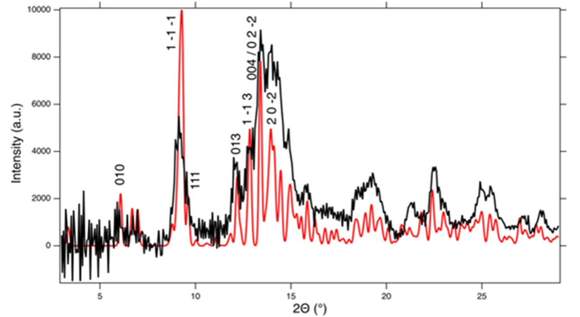
In order to further characterise the metamict mineral, another dark brown grain of this amorphous Y-silicate has been heat treated for 1 hour at 1000°C. The loss on ignition was ∼8 wt.%, which confirms that the low oxide sums reported in Table 9 are due to volatiles such as H2O. After heat treatment, the sample had turned light grey with a greenish tinge and greasy lustre, but it remained opaque. The greenish tinge of the grain later changed to a yellowish colour. Single-crystal X-ray diffraction on fragments of the heated sample yields very broad Bragg reflections, that can be indexed with the B-type unit cell of anorthoyttrialite-(Y)-1A (see below). Simulated powder diffraction with these crystal fragments, applying a Gandolfi type motion, renders a diffraction pattern that is very similar to that described in Table 3. The pattern is visually compared to the calculated powder pattern of anorthoyttrialite-(Y)-1A in Fig. 9, where a slight 2θ-offset has been applied to the measured data in order to align its peaks with the calculated pattern. Le Bail refinement of the diffraction pattern obtained from the heat treated grain yields the following unit cell parameters: a = 6.547(8), b = 6.671(8), c = 11.935(17) Å, α = 94.66(14), β = 90.11(14), γ = 92.50(10)° and V = 519.0(8) Å3. Though this unit cell is obviously smaller than that of non-metamict and untreated anorthoyttrialite-(Y)-1A (Table 4), it shows that the metamict Y-silicate from Stetind is structurally similar to anorthoyttrialite-(Y), but differs from thalénite-(Y) and also from the previously described low-form of yttrialite-(Y) (Lyalina et al., Reference Lyalina, Zozulya, Savchenko, Tarasov, Selivanova and Tarasova2014), with its monoclinic symmetry and [Si2O7]6– sorosilicate groups. It is unlikely that the amorphous phase only transforms to the B-type polymorph of anorthoyttrialite-(Y) during heating, as the single-crystal diffraction results indicate homogeneous recrystallisation rather than a reconstructive transformation process, that would probably involve the nucleation of numerous randomly oriented crystals. These results indicate that in the Stetind pegmatite anorthoyttrialite-(Y) occurs in both a non-metamict (low Th) and a metamict (high Th) form in close proximity. As the Th-rich, metamict crystals are mostly anhedral, in contrast to the sub- to euhedral crystals of anorthoyttrialite-(Y), we assume that the former was present in the fluorite prior to the Caledonian recrystallisation and therefore crystallised under different chemical and PT-conditions. It should be noted that both keiviite-(Y) and thalénite-(Y) are present in this material; keiviite-(Y) forms microcrystals in small cavities while thalénite-(Y) was found both as microcrystals in the cavities and as anhedral masses associated with the metamict Y-silicate. In terms of Th-content and annealing products at 1000°C, the metamict Y-silicate from Stetind is similar to the yttrialite described by Nilssen (Reference Nilssen1971) from Ivedal in southern Norway.
Simulated powder diffraction of heat treated, metamict Y-silicate from Stetind with a 2θ-offset of –0.25° (black curve, MoKα-radiation). The red curve shows the calculated powder diffractogram of anorthoyttrialite-(Y)-1A with indices hkl for selected peaks.

Conclusions
Anorthoyttrialite-(Y)-1A is isostructural with the B-type or α-form of the synthetic rare earth disilicates. A modular aspect of the structure of anorthoyttrialite-(Y) is indicated by the existence of its polytypic 2A-modification. While the crystal structure of anorthoyttrialite-(Y)-1A results from stacking of two types of layers or modules, with a four-layer repeat, the crystal structure of anorthoyttrialite-(Y)-2A, results from a different stacking sequence of such layers, with an eight-layer repeat. The tetragonal A-type structure of the rare earth disilicates, present in the mineral percleveite-(Ce), can be interpreted using a similar modular approach with just one type of layer.
Metamict, X-ray amorphous Y-silicate from the same location as anorthoyttrialite-(Y), but with significantly higher Th, Ca and F concentrations than those detected in holotype or cotype anorthoyttrialite-(Y), recrystallises when heat treated at 1000°C. Even though the recrystallised phase is still poorly crystalline, it is apparently composed of few uniform crystal lattices with unit cell dimensions similar to anorthoyttrialite-(Y). The obtained diffraction pattern is in agreement with the experiments reported by Nilssen (Reference Nilssen1971) for yttrialite-(Y) with moderate Th-content, but differs from results reported by Ewing and Ehlmann (Reference Ewing and Ehlmann1973) and by Ito and Johnson (Reference Ito and Johnson1968), who obtained the monoclinic low-form of yttrialite-(Y) at 1000°C and the B-type structure only, at 1200°C, albeit for yttrialites with significantly higher Th-contents.
Supplementary material
The supplementary material for this article can be found at https://doi.org/10.1180/mgm.2024.106.
Acknowledgements
Sample preparation was carried out by Peter Stutz. Stefanie Heidrich conducted the electron microprobe analysis. The authors would like to thank Cees Baas at Bruker Nederland BV for continued support of the KappaCCD instrument. Comments by Igor V. Pekov and by an anonymous reviewer helped to improve the manuscript.
Competing interests
The authors declare none.


 Open access