
I. INTRODUCTION
The proliferation of electronic devices in our digital age has necessitated more convenient methods of power transmission. One technology currently filling this need is resonant induction power transfer (IPT), which can trace its origins to the late-19th century [Reference Tesla1]. In this technique, electrical power is transmitted over short distances using resonant magnetic coupling between two coils [Reference Pinuela, Yates, Lucyszyn and Mitcheson2, Reference Covic and Boys3]. Owing to coupling being maximized when the transmitter and receiver share the same dimensions, IPT works best for single receiver/transmitter pairs or when multiple receivers can sequentially share one transmitter, as would be the case in dynamic electric vehicle (EV) charging [Reference Suh and Kim4]. The major disadvantage of IPT is when multiple devices require power at the same time, or when a single device requires power over a large area. In order to implement IPT in large scale multi-load situations, either a large coil would need to be constructed that encompasses the entire area, sacrificing transfer efficiency through reduced coupling; or the entire area would need multiple imbedded transmitters. Both the wiring complexity and cost associated with such endeavors makes either option impractical.
To fill the void of large area, multi-load power transfer without the use of interconnected cables, we propose a technique based on single-wire no-return power transmission (SWNR). The concept of SWNR was originally developed by Nikola Tesla in the late 1800s [Reference Tesla5, Reference Tesla6]. In Tesla's approach, loads were placed in various configurations along a resonant transformer which received power when the transformer was placed into resonance with its stray capacitance [Reference Tesla7, Reference Anderson8]. Completing the circuit with stray capacitance effectively eliminates the need for a physical return cable. Tesla called this “transmission through one wire,” and it formed the basis of many of his scientific endeavors. Since Tesla, few researchers have worked in this area [Reference Avramenko and Avramenko9, Reference Bank10]. Nearly all subsequent demonstrations of SWNR transmission, or variations thereof, are qualitative and require high driving voltages, making power transfer to devices unsafe in the vicinity of people.
Here we present a low-voltage variation of SWNR designed to operate over surfaces. Such surfaces may include any conductive object from a mat or nightstand to a cabinet or a conference table. The load in our system is not viewed as an external element, but as an integral part of the transmission line enabling efficient power transfer at resonance through internal dissipation. In brief, an alternating-current (AC) power signal is applied to a conductive surface. The connection of a helical receiver to the surface drives the receiver in resonance with its surrounding stray capacitance delivering power to a load attached to the receiver at any location on the surface. Only non-radiating resonant modes are excited, confining the energy within the system.
II. THEORY OF OPERATION
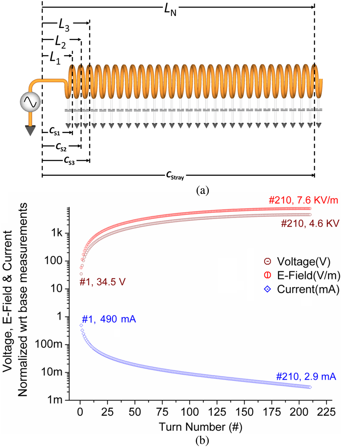
The governing principle of our single-contact system is based on exciting an evanescent (standing wave) mode inside a slow-wave helical resonator where the input electric and magnetic field vectors undergo temporal and spatial phase transitions as a function of the geometry and aspect ratio of the winding. The receiver is constructed from a solitary wire that is coiled and operates as a special case of a quarter-wave transmission line with an open circuit termination. At its resonating frequency, each turn of the helix is in self-resonance depending on the electrical parameters at that turn viz. the resistance, inductance, and capacitance distributed across the physical length of the helix. The distributed circuit model of the system can be represented as shown in Fig. 1(a). The circuit behaves similar to a series RLC resonator. However, unlike a lumped RLC resonator, the inductance and capacitance are cumulatively distributed causing changes in the quality of resonance at each turn. In a typical transmission line, the output electric field as a function of position d (fractional wavelength) is represented as
 $$E_{out}=E_{in} e^{j\lpar \gamma d+\omega t\rpar }\comma \;$$
where γ is the propagation constant represented as γ = α + j β, α being the attenuation factor and β the phase constant; and ω is the angular frequency. The propagation constant can be looked upon as the Euler representation of the spatial phase relationship (φ) between the E- and H-field vectors at each point in the transmission line. However, the special case operation of our system makes β a function of the position d which is not a constant along the line (helix); causing γ to also become a function of the geometry and no longer a constant. This non-constant γ may be redefined as a propagation factor which may or may not be a constant depending on the system's operational regime. Such a formulation accounts for the build-up of electric field at the termination end of the helix through the conservation of energy [Reference Heaviside11] since α → 0 at the terminal end. Conventional transmission line theory [Reference Terman12, Reference Moura and Darwazeh13] considers β as a constant. A careful analysis, with the strictest condition of achieving perfect reflection at the terminal end, accounts for a magnitude of field amplification by a factor no greater than 2.5092 [Reference Terman12] or 2 [Reference Moura and Darwazeh13] times the input (following wave reflections) considering the magnitude of the propagation constant. However, the build-up in our special case operation is governed by the resonance parameter distribution following:
 $$\left\vert {E_i } \right\vert =\left({\left\vert {E_{i - 1} } \right\vert +E_0 \, e^{j\left\vert {\alpha _i+j\beta _i } \right\vert d_i } } \right)\cdot e^{j\omega t}\comma \; \quad \forall i=[1\comma \; N] \comma \;$$
where d i = (λ i /N) = (π/2)(1/Nβ i ) is the fractional quarter-wavelength perceived by the wave at the ith turn of the helix. λ i is the fractional wavelength traversed by the propagating wave at each ith turn and is a function of the geometry of the helix. The obtained voltage becomes a function of the helical length (l) per turn given by
 $$\left\vert {V_{TER} } \right\vert =\sum\limits_{i=1}^N {\left\vert {E_i } \right\vert \cdot i \cdot l}.$$
(a) Distributed circuit model of a helical resonator. (b) The electric field (kV/m – red), voltage (kV – brown), and current (mA – blue) distributions per turn of the helical resonator.
Following the generalized current–voltage phase relationship in an inductor, the current distribution at each turn becomes
 $$\left\vert {I_i } \right\vert =\displaystyle{{\left\vert {V_i } \right\vert } \over {\omega L_i }}{\rm\comma \; }\quad {\rm where}\; \; L_i=L_{i - 1}+\lpar i \cdot L_{self} \rpar \comma \;$$
L i is the cumulatively distributed inductance along the line (helix) at the ith turn; and L self is the self-inductance of each turn dependent on the core material, turn radius, and gauge of wire.
Simulation results based on observed phase shift and input current and voltages gives the estimated electric field, voltage, and current distribution in the helix as a function of physical turn number i as shown in Fig. 1(b). A more detailed discussion on the theoretical model and the distribution parameters is beyond the scope of this report and will be communicated shortly in an upcoming article. To a more curious reader, the authors would like to draw attention to prior theoretical model formulations [Reference Terman12–Reference Kraus15]. It should be noted that the amplified field at the termination end is a restricted field and minimally radiative in accordance with slow-wave antenna theory [Reference Kraus15, Reference Bansal16]. Following the distributed circuit model, the cumulative stray capacitance acts like a virtual load alternately storing energy between itself and the entire helical inductance at the resonance frequency. From Fig. 1(b), the voltage is the maximum and the current is almost zero at the termination; whereas at the base, it is just the reverse. In addition to the spatial phase φ TER , the temporal phase angle θ TER between V TER and I base is also 90° for an ideal system with zero radiation. For a real world system, the portion of the wave transmitted at the terminal end will reduce both the spatial and temporal phases (φ TER and θ TER , respectively). The output power of the receiver will thus be complex and mostly reactive when θ TER is near 90°. In contrast, a radiating antenna has an output that is mostly active with a 0° phase, thus making β a constant (using small angle approximation). For our system, the complex output power S TER at the receiver's termination is
 $$S_{TER}=P_{TER}+jQ_{STORED}=I_{base}^2 \cdot R_{Rad}+jI_{base}^2 \cdot X\comma \;$$
where P
TER
is the active power component leaving the system as electromagnetic radiation and is equal to the squared magnitude of the current at the base of the helix (I
base
) multiplied by the radiation resistance R
Rad
; Q
STORED
is the reactive or stored energy in the receiver at resonance which represents the near-field component and is equal to the multiplication of I
base
2 with the reactance (X=either, $\sum\nolimits_{i=1}^N {\omega L_i } $
or 1/(ω C
STRAY
) depending on the cycle). For a tightly wound helix close to the ground plane and small compared to the wavelength, the radiation resistance present in the system is very low [Reference Kraus15]. The active power portion of equation (5) can be related to the input of the base of the helix by
$\sum\nolimits_{i=1}^N {\omega L_i } $
or 1/(ω C
STRAY
) depending on the cycle). For a tightly wound helix close to the ground plane and small compared to the wavelength, the radiation resistance present in the system is very low [Reference Kraus15]. The active power portion of equation (5) can be related to the input of the base of the helix by
 $$P_{OUT}=P_{IN} - P_{Diss}\comma \;$$
where P IN is the total active input power delivered to the system, and P Diss is the power dissipated through internal losses (wire resistance, eddy currents, etc.) along the receiver. A real load connected to the system increases the total internal resistance (R Diss ) and functions almost identically to a series RLC oscillator circuit where the load is placed in series with the inductive element, in contrast to a conventional transmission line where the load is placed in parallel with the RLC capacitance. To a first order approximation, a lumped series RLC circuit can be successfully used to model input voltage, current, and frequency response at the source (though fails to accurately model these values at the load). A real load in our system may therefore be viewed as part of the transmission line instead of a separate component. If the source voltage is held at a constant value, the connection of the real load always acts to lower the input current. Raising the source voltage and bringing the current back to the initial unloaded value will deliver active power to the load. This method allows energy to be efficiently transferred from source to load with only a single conductor as the power transport medium.
A conductive object may act as the feedline to the quarter-wave system, bridging the connection between the receiver and power source. If the object's dimensions are small compared to the operating wavelength, the applied voltage from the source will be roughly uniform over the entire surface area of the object. Placement of the receiver onto the object's surface allows the receiver to become energized, while the object remains at a low voltage due to the nodal location in the standing wave pattern shown in Fig. 1(b). The receiver's near-field thus becomes extended over the conducting object. Lower frequencies will enable power transmission over larger areas. As a hypothetical example, a cubic object having 15 m sides with an applied frequency of 1 MHz would still maintain a voltage nodal magnitude over the entire surface area. At the free end of the receiver, the standing wave pattern produces a voltage anti-node. This higher voltage may be easily insulated or shielded, leaving the whole system safe for human contact. It should be pointed out that with the system in resonance with stray capacitance, any intrusion (person) into the capacitive region detunes the system for a fixed driving frequency. This detuning will reduce the E-field and power transmitted through the quarter wave resonator. Sufficiently isolated terminal fields will be small enough for safe human contact especially for low-power applications. To mitigate this environmental sensitivity, frequency rastering or feedback mechanisms could be used to compensate for the changes in capacitance, thereby retuning the system to resonance and ensuring efficient power transfer. For high-power applications, the detuning of the system may be left as a feature to improve operational safety.
III. EXPERIMENTAL SETUP
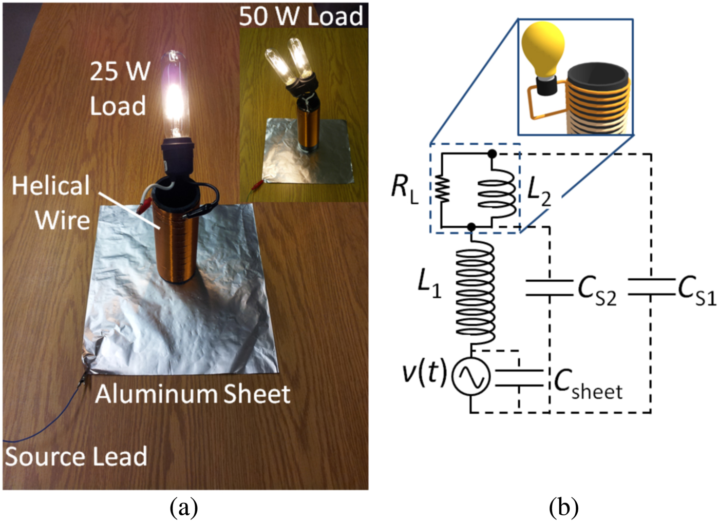
A photograph of the experimental setup is shown in Fig. 2(a). The receiver (labeled helical wire) was constructed from 22-gauge magnet wire tightly coiled 210 times around a black acrylonitrile butadiene styrene (ABS) pipe. The load was placed in parallel with the uppermost six turns of the coil. An aluminum foil sheet (25 × 25 cm) formed the single-contact transmission surface for the coil. One output terminal of a high-frequency power source was connected to the sheet (labeled source lead), whereas the other output terminal was electrically grounded. The receiver was fastened to the ABS frame such that when the receiver was resting upright, its bottom terminal made electrical contact with the sheet. The resonant nature of the system made direct measurements at the load difficult, as direct connections of standard equipment at the free end of the receiver drastically changed the operating conditions of the system. The least-invasive method found was to measure the voltage and current values at the output of the power amplifier (which is the input of the receiver). These values and their relative phase angles were recorded with a current probe and a standard 10× voltage probe. When the frequency of the power supply was tuned to match the standing wave resonant frequency of the receiver, the load would absorb power regardless of the receiver's position on the aluminum sheet. We observed that the insertion of a dielectric between the sheet and receiver increased the power capacity of the system as higher input voltages could be safely applied to the sheet. It should be noted that the capacitance formed between the bottom terminal and the sheet acts as impedance and not an energy storage component. It is the stray capacitance responsible for the energy storage in the system related to (1/2)C STRAY V TER 2. The insertion of the dielectric and the formation of a connecting capacitance allowed the system to function in a quasi-wireless state where a direct, bare-metal connection was not required. The effect of sheet insulation on the system was further investigated to determine the system's response.
(a) Photograph of the experimental setup. (b) Lumped circuit schematic used to model the system.
IV. RESULTS AND DISCUSSION
Figure 2(b) shows the equivalent lumped circuit schematic of the single-contact system. The stray capacitances C S1 and C S2 are non-tangible elements. The aluminum sheet produces another stray capacitance (C SHEET ) that is shunted with the supply. Generally the reactance of C SHEET at the operating frequency is very large and can be neglected for small sheet sizes. Larger sheet sizes require compensation at the supply to negate the effects of C SHEET which increases the input current and consequently reduces efficiency. Using experimentally determined parameters, the system response was simulated for various loads. The simulated model predicted a maximum power transfer to the receiver when the load resistance approximately equaled the impedance magnitude of inductor L 2. To experimentally verify this, a potentiometer (rated for 0.5 W) was used as the load. We recorded the input power to the system with varying load resistances ranging from 0.7 to 3000 Ω for both a bare and an insulated aluminum sheet. The input current from the source was maintained at 30 mA, while the input voltage was allowed to fluctuate. This produced a typical Gaussian-shaped power curve as shown in Fig. 3(a). Maximum power transfer was obtained when the load resistance was between 90 and 190 Ω for both the bare (red square trace) and insulated (blue diamond trace) sheet as shown in Fig. 3(a). The inductance of L 2 was 5.887 µH. At the resonant frequency of the system, this section of coil had an estimated impedance of 97 Ω. This result approximately matched the simulated power transfer curve of the model (black triangular symbol trace in Fig. 3(a)) with peak transfer power nearly half of what was experimentally observed. It should be noted that the power curves of Fig. 3(a) do not represent just the power dissipated in the load but rather denote the power dissipated by the whole system: aluminum sheet, receiver, and load combined.
(a) Input power to the system at constant current as a function of load resistance. The red trace (square) corresponds to power transferred over a bare aluminum sheet; the blue trace (diamond) corresponds to transmission over an insulated aluminum sheet; the black trace (triangle) is the simulated response of the model over a bare aluminum sheet. (b) Transmission efficiency over an aluminum foil sheet with increasing layers of 61 µm thick polypropylene sheets. The orange trace (diamond) is for a 50 W load while the green trace (square) is for a 25 W load.

To demonstrate higher levels of power transmission, 25 W incandescent light bulbs were used as loads. The amount of power dissipated in the loads was quantified by applying 60 Hz mains power (120 V rms ) to the light bulbs and measuring the input voltage and current with a digital multimeter. At the same time, the relative irradiance of the light bulbs was measured with an optical power meter at a distance of 30 cm. The light bulbs were then connected to the single-contact system without altering their distance from the optical power meter. The high-frequency alternating voltage was applied and increased until the reference irradiance was observed.
For the bare aluminum sheet, the total input power was 61 W with an attached 50 W load. The losses in the system are the summation of AC wire resistance, electromagnetic radiation, and eddy currents in the aluminum sheet. The wire resistance at 2.2 MHz was 5 Ω, dissipating 0.9 W. The power dissipated in eddy current losses that are generated in the aluminum sheet at the base of the wire can be estimated by Dunlop [Reference Dunlop17]
 $$P_{Eddy} \approx \displaystyle{{\pi ^2 d^2 f^2 B_{peak}^2 } \over {16\rho }} \cdot {\rm \Lambda\comma \; }$$
where d is the diameter of the helix, f is the operating frequency, B peak is the peak magnetic field in the receiver, ρ is the resistivity (2.82 × 10⁻⁸ Ωm for Al.), and Λ is the volume of the aluminum sheet affected by the eddy currents. The wire at the base of the helix was wound 1.25 mm above the bottom of the ABS pipe. The estimated magnetic field at this distance from the sheet was determined to be approximately 85 µT. For a 6 µm thick aluminum foil, the volume affected by the eddy currents was 3.6 × 10⁻⁹ m3, yielding a calculated value of ~10 W. To improve efficiency, these eddy current losses could be greatly mitigated with sheet perforations, strip layering, or other techniques.
The electromagnetic radiation produced from the system may be determined from either accurately measuring the temporal phase angle between standing wave electric and magnetic field or by accounting for all the dissipative losses then subtracting them from the total input power. If the first approach is used, the temporal phase angle θ TER must be measured very close to the receiver as the angle reduces with distance. The standing wave current is directly proportional to the magnetic field and thus can be more easily measured than the emanated B-field. The output E-field at the receiver's termination can be measured with a simple wire probe. The radiation resistance in terms of phase angle is
 $$R_{Rad}=\displaystyle{{\sum\nolimits_{i=1}^N {\omega L_i } } \over {\tan \left({\phi _{TER} } \right)}}\comma \;$$
where L N is the total accumulative inductance of the receiver following the inductance in equation (4). The equipment used to measure the phase angle can be the limiting factor when applying equation (8). Our oscilloscope had difficulty measuring beyond 0.1° with any accuracy; even with the highest time averaging. Owing to this, we used the second approach given by equation (6). After removing the aluminum sheet and replacing it with a standard coax cable to eliminate effects of eddy currents, R Rad was determined to be 0.425 Ω corresponding to a radiated power of 0.1 W at the input of the receiver (about the same radiated power of a cell phone but with a frequency three orders of magnitude lower). This is the same radiated power predicted by the mathematical model of Fig. 1(b) when the simulated source voltage (35.4 V) is multiplied by the end terminal current of the helix (2.9 mA) as these two parameters are temporally in phase. In practice, however, the end terminal current of the receiver is very difficult to measure without changing the operating parameters of the system.
The basic equation for efficiency η, neglecting losses in the source, is given by
 $$\eta=\displaystyle{{P_L } \over {P_{IN} }}=\displaystyle{{R_{Load} } \over {R_{Wire}+R_{Rad}+R_{Eddy}+R_{Load} }}\comma \;$$
where P L is the power consumed in the load (25 or 50 W) as correlated with the relative irradiance. The efficiency of the system is plotted in Fig. 3(b) for various layers of insulation starting at zero with bare aluminum. Each insulation layer consisted of a 61 µm thick polypropylene sheet that was inserted between the receiver and aluminum foil. The maximum efficiency obtained was 83% with two insulation layers (or 122 µm thick polypropylene neglecting air pockets) for a 50 W load. This improvement in efficiency may be due to a better impedance matching between the source and receiver with a slight reduction in eddy currents.
The frequency response of the system was plotted using the electric field (E-field) maxima present at the top (termination) of the receiver for a 25 and 50 W load (Fig. 4). This field was measured with a wire probe at a distance of 25 cm. With no load connected and driven at resonance, the measured resonant frequency of the system was 2.408 MHz with a quality factor of 153. We anticipate that most applications will always have an attached load, making such an unloaded and resonating situation a rare occurrence. When the loads were connected, the resonant frequency reduced to 2.39 MHz and the quality factor changed as shown in Fig. 4. The area under the Quality factor curve essentially gives a measure of the stored energy inside the coil as a function of load for the same input voltage. It also points to the limit of maximum load driving capability for a fixed input voltage where, for a low enough Q, the energy stored would become negligible and the system would cease to resonate. Such a response is characteristic of a driven damped harmonic oscillator where the load is internal to the resonator and the power transfer efficiency for a given load is proportional to the Q-factor of the system. The large frequency shift seen in Fig. 4 occurs due to the mutual inductance interaction between equivalent lumped inductances L 1 and L 2 (referring to the inductances in Fig. 2(b)) where the value of load dictates the amount of mutual coupling seen between the two inductances. If the winding direction of L 2 was reversed, the frequency would shift up instead of down with attached load.
Frequency response of the system with a 25 W load (middle purple trace), 50 W load (left red trace), and no load (right blue trace). The electric field magnitude (measured at 25 cm from the coil), the quality (Q) factor, and the resonant frequency all decrease with the connection of the load. The Q-factor versus load is plotted at the top. The shaded green area represents the amount of reactive power stored in the receiver. As the load increases, so does the internal dissipation of the system.

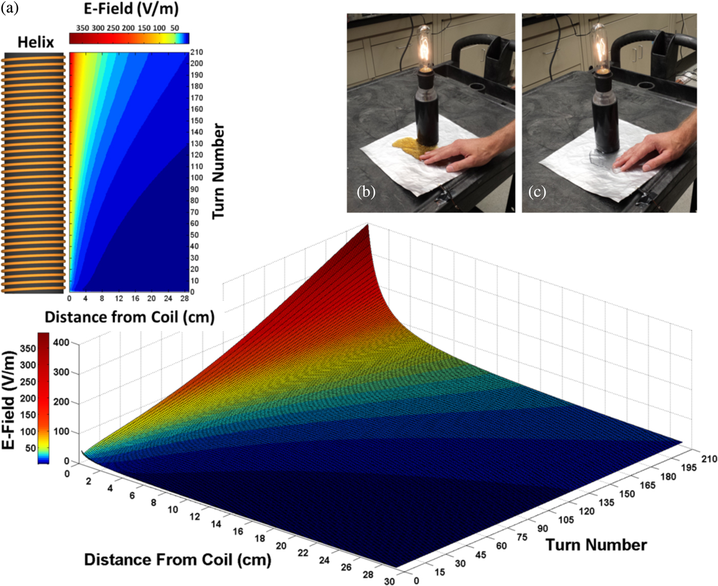
The magnitude of the measured E-field also significantly reduced when the load was connected. Three-dimensional (3D) surface plots of the emanating E-field distribution around the receiver were simulated in MATLAB and are shown in Fig. 5(a). The E-field magnitude recedes rapidly with distance away from the receiver [Reference McDonald18]. The average E-field spanning the area around the receiver is small and well within safety standards for public exposure to electromagnetic fields [19] due to the field's rapid decay. As the receivers are reduced in size, the effective average E-field magnitude over the area will also reduce. At the present system efficiency of 83%, a power transmission of 10 W requires an applied voltage of 24 V RMS to the bare aluminum sheet, allowing the system to function within safety standards for low-voltage operation [20]. By further reducing internal losses, greater power may be delivered for the same low-voltage input. If the aluminum sheet is insulated, the system power may be safely increased to well past 50 W. Usage of a 61 µm thick polypropylene film gave a contact potential of 10 V RMS when 144 V RMS was applied to the sheet. In addition to the detuning phenomenon discussed earlier, it should be noted that the negative terminal of the source is not used in this system which further increases the safety aspect for this form of power transmission. Pouring tap-water or soft-drinks over the insulated aluminum sheet showed no alteration in delivered output operation with the spilled fluids completely harmless to human contact. This is shown in Figs 5(b) and 5(c).
(a) 3D surface plot simulation of the emanating E-field with respect to receding distance from the receiver (helix). The simulated results are in good agreement with the measured E-field results of Fig. 4. Photograph of 25 W light bulb operated on an insulated aluminum foil sheet with (b) a soft-drink and (c) tap-water spill.
We have had great success in converting everyday objects into single-contact locations through the connection of an AC power signal (Fig. 6). The measured transmission efficiency of the larger objects (Figs 6(b) and 6(c)) was found to be approximately 40% without any modifications or source compensation. This is mainly due to the large capacitive loading (C SHEET of Fig. 2(b)) these objects present to the source which increases the driving current, generating more losses in the system. Placing the helical receiver inside the desk greatly reduced the power delivered to the load through Faraday shielding. This can be overcome by energizing a separate conducting surface inside the desk or cabinet while keeping the desk itself unconnected or floating. Power may then be delivered to the receiver through the connection of both inner and outer surfaces.
Supplying power to a 25 W light bulb through various conductive objects. (a) Two receivers, each with attached 25 W loads, of different frequency powered on the same aluminum foil sheet simultaneously. The bottom right resonator is encapsulated in ABS to allow safe handling when in operation; (b) a metal cabinet coated with electrically insulating paint; and, (c) a metal desk with a plastic top surface. The light bulb with coil may be placed anywhere on the desk or cabinet surface to receive power, including the sides.

V. CONCLUSIONS
After demonstrating the operation of a 50 W load over a 25 cm × 25 cm surface at an efficiency of 83%, we then applied the single-contact method to various objects around the laboratory. During the experiments, the maximum input voltage applied to an insulated aluminum sheet was 144 V RMS (for a 50 W load) and 73 V RMS for the desk and cabinet (both with 25 W loads). These voltages are substantially lower than prior demonstrations of single-wire and wireless capacitive systems which require inputs of the order of several kilovolts without the added benefit of near-field surface propagation. Presently, up to 10 W may be achieved at voltage values that meet safety standards for low voltage operation (25 V RMS ).
The utility of single-contact power transmission is only limited by the imagination. One promising application of this technique is the charging and powering of personal electronics. The inductive “charging pad” concept could instead be implemented as a single-contact “charging sheet” with greater transfer coverage, improved convenience, and reduced cost. Beyond personal electronics, this technology could be transformative in many research areas. Robotic systems could be made lighter and their wiring less complex; in particular, programmable matter devices could be simplified by severing their dependence on internal batteries [Reference Gilpin, Knaian and Rus21]. Future scaling of the power capacity could reduce the mass of copper wire in homes, aircraft, and automobiles by more than half (through the elimination of the return conductor) while simultaneously reducing the wiring complexity. Conventional electrical outlets could one day be replaced by metal foil sheets or conductive paint, transforming entire walls into power strips while remaining completely paintable. Such refinements may also allow electric vehicles to be charged in-motion with inexpensive conductive mats placed periodically along the road, without needing to drastically alter current roadway infrastructures. Although not optimized, the surface size, power capacity, and efficiency of the presented single-contact system are more than sufficient to operate contemporary low-power devices, with higher power applications being a definite future research direction.
Supplementary material
The supplementary material for this article can be found at http://www.journals.cambridge.org/WPT
ACKNOWLEDGEMENTS
We would like to acknowledge the support and funding of the Canada Excellence Research Chairs (CERC) Program and the Faculty of Engineering at the University of Alberta. Author J. A. J. Backs was supported in part by the Natural Sciences and Engineering Research Council of Canada and Alberta Innovates – Technology Futures.
 Charles W. Van Neste is a Research Associate working in the Chemical and Materials Engineering Department at the University of Alberta. He obtained his Ph.D. degree in Electrical Engineering from Tennessee Technological University in 2009. Dr. Van Neste's primary research involves alternative forms of energy generation and transmission. His areas of expertise include wireless and quasi-wireless power transfer, electronics and instrumentation, and electric machine design.
 John E. Hawk received his Bachelors of Science degree in Physics and Mathematics at the University of Memphis in 2000. While continuing graduate studies in Applied Physics at the University of Tennessee, Knoxville, he began working as a research associate at the Oak Ridge National Laboratory. He is currently pursuing a Doctorate in the Chemical and Materials Engineering Department at the University of Alberta (CERC Graduate Fellow). His areas of interest are mechanical and electrical resonant structures, atomic force microscopy, software development, and theoretical analysis.
 Arindam Phani is a CERC Graduate Research Fellow (Ph.D.) at the University of Alberta in the Department of Chemicals and Materials Engineering. His interests lie in fundamental understanding of physics of resonant systems. He is currently studying the role of dissipation in macro, micro and nano-scale electrical and mechanical resonant systems and developing sensors thereof. His other areas of interest include optical, opto-electro-mechanical transduction, sensors, and measurement devices.
 Jonathan A.J. Backs is a Canada Excellence Research Chairs interdisciplinary Ph.D. student at the University of Alberta. His current research integrates the fields of materials engineering and wildlife ecology to understand and prevent wildlife–train collisions. He holds a prestigious Graduate Student Scholarship from Alberta Innovates – Technology Futures and has previously held an Alexander Graham Bell Canada Graduate Scholarship from the Natural Sciences and Engineering Research Council of Canada. Jonathan's broad background ranges from multi-physics computer modeling of in-situ soil remediation to research in near-field scanning optical microscopy. He received a B.Sc. degree in Engineering Physics, with Distinction, from the University of Alberta in 2010.
 Richard Hull is a research scientist working in the Chemical and Materials Engineering Department at the University of Alberta. He graduated from Oxford University in 2009 with a degree in Nanotechnology. His initial career was in the aerospace industry as an Electronics R&D Engineer on defense projects dealing with military radar systems in the UK. He later worked for the Canadian Space Agency at SPAR Aerospace in Toronto. His area of expertise includes power electronics, data processing, telecommunications, and robotics.
 Tinu Abraham is a Canada Excellence Research Chair Ph.D. student in the Department of Chemical and Materials Engineering at the University of Alberta. She is currently researching the feasibility of heating oil sands using near-field, standing wave resonance for in-situ reservoirs with the overall aim of reducing water and energy consumption in bitumen extraction. Her research interests include exploring enhanced oil recovery techniques and other sustainable methods of producing energy.
 Samuel Glassford is an undergraduate student currently pursuing a B.Sc. in Electrical Engineering at the University of Alberta. He has worked for Dr. Thomas Thundat as a NSERC Undergraduate Student Research Award recipient and for Dr. Thomas Thundat's Wireless Power Transfer lab under the instruction of Dr. Charles Van Neste during the following semester. Upon graduation, Mr. Glassford hopes to pursue a career in power transmission.
 Adam Pickering is an undergraduate student currently pursuing a Bachelors of Science degree in Electrical Engineering at the University of Alberta. He interned for Dr. Thomas Thundat in the summer of 2013 where he built electrical resonators in Dr. Thundat's Wireless Power Transfer laboratory under the instruction of Dr. Charles Van Neste. His areas of interest include electronics and wireless power transmission.
 Thomas Thundat is a Canada Excellence Research Chair Professor at the University of Alberta. He received his Ph.D. in Physics from the State University of New York at Albany in 1987. Dr. Thundat is the author of over 280 publications in refereed journals, 45 book chapters, 40 patents, and over 130 invited talks. Dr. Thundat's research is currently focused on novel physics and sensing applications.


 Open access