


Introduction
Thermal-barrier coatings (TBCs) are refractory-oxide ceramic coatings applied to the surfaces of metallic parts in the hottest part of gas-turbine engines (Figures 1and2), enabling modern engines to operate at significantly higher gas temperatures than their predecessors (see recent reviewsReference Evans, Mumm, Hutchinson, Meier and Pettit1–Reference Vaßen, Ophelia-Jarligo, Steinke, Emil-Mack and Stöver6). Gas-turbine engines, used to propel aircraft and to generate electricity, are Carnot engines where their efficiency and core power are directly related to the gas temperature entering the turbine section.Reference Bathie7, Reference Perepezko8 Further increases in the energy efficiency of gas-turbine engines, both to increase the electricity output and, for jet engines, the thrust-to-weight ratio and durability, will rely on further improvements in TBCs. At the same time, as gas temperatures are increased in the pursuit of higher engine efficiency, there are new challenges to existing TBCs.
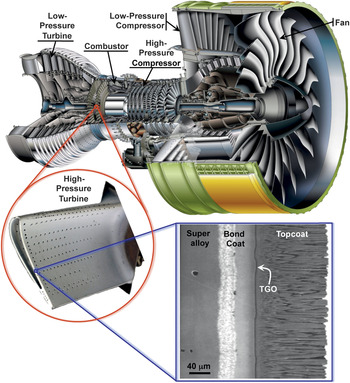
Cutaway view of Engine Alliance GP7200 aircraft engine, photograph of a turbine blade (∼10 cm long) with thermal-barrier coating (TBC) from the high-pressure hot section of an engine, and a scanning electron microscope (SEM) image of a cross-section of an electron beam physical vapor deposited 7 wt% yttria-stabilized zirconia TBC. (Engine image courtesy of Engine Alliance, turbine blade photograph courtesy of YXLON, and the SEM micrograph is from Reference 44.) TGO, thermally grown oxide.
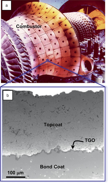
(a) Photograph of an annular combustor with thermal-barrier coating (TBC) and (b) cross-sectional scanning electron microscopy image showing an air plasma-sprayed 7 wt% yttria-stabilized zirconia TBC.Reference Padture, Gell and Jordan2 TGO, thermally grown oxide. Combustor image courtesy of Siemens Energy Inc.
To place this in context, gas-turbine engines are a $42 billion industry worldwide (2010), with ∼65% of the sales accounting for jet engines and the remainder land-based engines for electricity generation.Reference Langston9 The latter, fueled by natural gas or liquid fuels, produce ∼25% of all electricity in the United States and ∼20% worldwide (2010).10 With the anticipated worldwide growth of electricity demand and the recent discovery of vast shale gas resources, the number of gas-turbine engines in service will inevitably grow in the coming decades.Reference Langston9 Similarly, airline traffic is expected to double in the next 20 years,11 while at the same time, there is a need to reduce high-altitude NOx pollution produced by jet engine exhausts.12 Together, these developments will require continued innovation in gas turbine technology and high-temperature engine materials, including TBCs and associated technologies.
Many engineering design factors influence the overall efficiency of gas-turbine engines, but a major step in increasing engine temperature and engine efficiency was the introduction of TBCs. Typically made of ∼7 wt% Y2O3-stabilized ZrO2 (7YSZ) ceramics, TBCs provide thermal insulation to the metallic/superalloy engine parts. These parts include the combustor (Figures 1 and 2); stationary guide vanes, rotating blades (Figure 1), blade outer air-seals, and shrouds in the high-pressure section behind the combustor; and afterburners in the tail section of jet engines. As illustrated in Figure 3, the gas-temperature increase facilitated by the use of TBCs, in conjunction with innovative air-cooling approaches, has been much greater than that enabled by earlier materials development, including the development of single-crystal Ni-based superalloys.
Progression of temperature capabilities of Ni-based superalloys and thermal-barrier coating (TBC) materials over the past 50 years. The red lines indicate progression of maximum allowable gas temperatures in engines, with the large increase gained from employing TBCs. Based on a diagram from the late Professor Tony Evans.

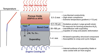
Originally, TBCs were introduced to extend the useful life of stationary engine parts such as the combustor, but in the late 1980s, TBCs were first used on rotating blades.Reference Schulz, Fritscher, Leyens, Peters and Kaysser13 However, TBCs were not “prime reliant”; in other words, the ceramic coating was not considered in the design of the temperature capability of the underlying metal parts. Today, TBCs are critical components in gas-turbine engines, and because the gas temperatures are typically higher than the melting point of the underlying metal parts, any TBC failure can endanger the engine.14 Furthermore, because of the coupled diffusional and mechanical interactions between the oxide ceramic coating and the underlying alloys at these high temperatures, it is essential to consider TBCs as a complex, interrelated, and evolving material system, consisting not only of the oxide ceramic coating (topcoat) itself but also the underlying superalloy engine part, and two other layers in between. These include a metallic bond-coat layer that is more oxidation resistant than the superalloy, and a thin, thermally grown oxide (TGO) layer that forms between the topcoat and the bond coat as result of bond-coat oxidation in-service. The bond-coat composition is designed to result in a TGO made of α-Al2O3—a mechanically robust, effective barrier to oxygen diffusion. Figure 4 illustrates this multilayer structure in a typical TBC system.
Schematic illustration of the multilayer, multifunctional nature of the thermal-barrier coating system (not to scale). The ceramic topcoat is deposited by electron beam physical vapor deposition (EBPVD) or air plasma-spraying (APS). Sandwiched between the topcoat and the metallic bond coat is the thermally grown oxide (TGO). Properties/functions and approximate thicknesses of the different layers are indicated.
During service, several kinetic processes occur in parallel. Interdiffusion between the bond coat and the underlying superalloy occurs, driven by chemical potential gradients; Al diffuses from the bond coat to form the TGO; and microstructural, chemical, and phase changes occur in all the materials, including in the ceramic topcoat itself, changing their very properties. Since all of these are thermally activated processes, the rates at which they occur are expected to increase exponentially with temperature, albeit with different activation energies. Furthermore, the processes generally lead to degradation and failure of the coating.
TBCs are also multifunctional: they must provide thermal insulation to protect the underlying superalloy engine parts, have strain compliance to minimize thermal-expansion-mismatch stresses with the superalloy parts on heating and cooling, and must also reflect much of the radiant heat from the hot gas, preventing it from reaching the metal alloy. Furthermore, TBCs must maintain thermal protection for prolonged service times and thermal cycles without failure. Typically, these times are 1000s of hours for jet engines being cycled numerous times between a maximum temperature of ∼1300°C and room temperature (takeoff/landing and on-ground), and 10,000s of hours for power-generation engines with fewer thermal cycles (maintenance shut-downs). However, the latter are now being increasingly employed to stabilize the electric grid connected to renewable sources (wind, solar), and, thus, these engines experience more frequent cycles to compensate for the inherent intermittency of renewables. TBCs need to do this without separating from the engine parts while also withstanding extreme thermal gradients (∼1°C μm–1) and energy fluxes (∼1 MW m–2). Not only are these demands extremely exacting but also are often conflicting: TBCs must have both low thermal conductivity and low weight; they must remain intact while withstanding large stress variations, both due to heating and cooling as well as under thermal shock; they must be chemically compatible with the underlying metal and the TGO; and they must operate in an oxidizing environment at maximum pressures of ∼10 atmospheres and maximum gas velocities exceeding Mach 1.
These demands and the desire to operate at higher temperatures reliably for longer times are driving new TBC innovations based on exploration of the underlying materials, processing sciences, and mechanistic understanding of degradation/failure and its mitigation. Several but not all of these key areas are highlighted in this issue of MRS Bulletin.
In this issue
Ceramic topcoat processing
Sampath et al. describe the oxide ceramic topcoat deposition processes and microstructures. Unlike more traditional thin films used in microelectronics and in materials-growth studies, these coatings are of intermediate thickness (100 μm to 1 mm), and they must be deposited at a high rate to incorporate porosity. Typical TBC porosity is ∼15%, which is essential for high strain compliance and reduced thermal conductivity, yet the TBCs need to be mechanically robust to resist fracture, erosion, and foreign object damage (FOD). Furthermore, TBCs need to be deposited on complex-shaped parts with highly curved surfaces, and at the same time the TBCs must have reproducible thermal and mechanical properties. Currently, TBCs are deposited by air plasma-spraying (APS)Reference Herman, Sampath and McCune15 or by electron beam physical vapor deposition (EBPVD).Reference Schulz, Leyens, Fritscher, Peters, Saruhan-Brings, Lavigne, Dorvaux, Poulain, Mevrel and Caliez16 Typically, the low-cost APS method is used to deposit TBCs on stationary engine parts (combustor, shroud, vanes), whereas EBPVD TBCs are used on the most demanding hot-section parts in jet engines such as blades and vanes. Today, both stationary and rotating hot-section parts in electricity-generation engines, which tend to be much larger than those in jet engines, use APS TBCs. The microstructures of APS and EBPVD TBCs are vastly different (see Figures 1 and 2), and each offer different advantages in terms of properties and performance. While processing science and technology of depositing 7YSZ TBCs is well established, the widespread introduction of improved TBCs of alternative compositions will ultimately depend on their reproducible and successful deposition commercially. Alternative TBC deposition methods with added advantages and versatilities are also being pursued.Reference Padture, Schlichting, Bhatia, Ozturk, Cetegen, Jordan, Gell, Jiang, Xiao, Strutt, Garcia, Miranzo and Osendi17–Reference von Niessen and Gindrat20
TBCs testing and evaluation
An equally big hurdle to developing improved TBCs is the sheer complexity and variety of failure modes and their dependence on engine operating conditions. Superficially, the failures are similar; the coating spalls off the engine part exposing the underlying metal to rapid oxidation or melting. However, a variety of mechanisms can be responsible for the observed failure.Reference Evans, Mumm, Hutchinson, Meier and Pettit1 In some instances, the TGO grows to exceed a critical thickness and spalls off, causing TBC failure.Reference Chan, Cheruvu and Vishwanathan21, Reference Schlichting, Padture, Jordan and Gell22 In others, the initially flat bond coat and TGO undergo a complex morphological instability—“rumpling” (Figure 5)—causing local separations that grow in size with thermal cycling until linking up to form a spall.Reference Tolpygo and Clarke23–Reference Heeg, Tolpygo and Clarke25 In still others, cavitation occurs in the bond coat and grows under thermal cycling.Reference Tolpygo26 In each of these cases, the failure location depends on the actual thermal and mechanical loading conditions in the coating. Typically, at moderate heat fluxes but high temperatures at the bond coat, failure is dominated by processes related to TGO formation and bond-coat inelastic behavior, where fracture occurs in the bond-coat/topcoat interface region. With increasing topcoat surface temperature and thermal-gradient, thermal-expansion mismatch starts to play a more dominant role, and fracture location typically shifts to within the ceramic topcoat.
(a) Cross-sectional scanning electron microscopy images showing the progression of thermally grown oxide (TGO) thickening and the evolution of local interface separations in an electron beam physical vapor deposited 7 wt% yttria-stabilized zirconia thermal-barrier coating (TBC) on a Pt-modified nickel aluminide bond coat with number of 1-h thermal cycles (1150°C peak temperature). (b) The plot shows the mean stress in the TGO stress measured through the topcoat using the photoluminescence piezo-spectroscopy technique. The different symbols refer to measurements on different coatings from the same deposition run. (Based on information from Reference 25.)

In some cases, spallation occurs as a result of impact from particles (FOD) carried along with the hot, combusted gas.Reference Chen, Wang, Yao, Evans, Hutchinson and Bruce27 In other cases, thermal-shock spallation of the coating can occur during rapid cooling. In still other cases, fine sand and particulates ingested into the engine (including volcanic ash) can melt into a silicate glass at high temperatures (>1200°C) on the TBC surface and wick into the TBC, decreasing its strain compliance and causing spallation upon cooling.
Both the crack driving force and the fracture resistance offered by the material also depend on the mechanical and thermophysical properties of the TBC system. These can change significantly with time at temperature. Also, these properties can be influenced significantly by the coating microstructure, which in turn is influenced by the process parameters used during the coating deposition. Even small variations of these parameters can lead to significant changes in coating microstructure, and thus to a wide variation in mechanical and thermophysical properties, resulting in a large scatter in system reliability, durability, and predictability. Thus, deterministic approaches for predicting TBC life can be often misleading, requiring the use of probabilistic approaches for predicting TBC life. From a manufacturing, as well as materials selection perspective, clarifying mechanisms of failure and being able to predict life remains an essential and central task in optimizing the coating system.
This has motivated the development of TBC testing methods and non-destructive evaluation techniques, especially under realistic conditions pertinent to engine operation, which can include high pressures (up to 10 atm.), high temperatures (up to 1400°C), steep thermal gradients (temperature differences up to 300°C), high gas velocities, and the presence of detrimental environmental species (e.g., water vapor, sand, ash, salt). The article by Vaβen et al. describes some of the common TBC failure modes and innovations in TBC testing and evaluation.
Topcoat ceramics
The majority of TBCs in use today are ZrO2-based having a composition containing ∼7 wt% Y2O3 (7YSZ). Originally, this ceramic was selected empirically based on its low thermal conductivity, high melting point, resistance to sintering, a demonstrated manufacturing capability for depositing it with constant composition, and long life in the resulting TBCs.Reference Schulz, Fritscher, Leyens, Peters and Kaysser13, Reference Stecura28–Reference Jones and Stern30 Unlike the cubic ZrO2 used in oxide fuel cells, oxygen sensors, and fake diamonds, which have higher Y2O3 content, 7YSZ is a metastable tetragonal phase (t’).Reference Clarke and Levi4 7YSZ has been shown to have unusually high fracture toughness due to ferroelastic toughening.Reference Virkar31, Reference Mercer, Williams, Clarke and Evans32 Unlike other transformation-toughened ZrO2-based ceramics, so-called “ceramic steels,”Reference Green, Hannink and Swain33 used in bearings, cutting tools, and knives, the toughness in 7YSZ does not arise from the martensitic transformation (an irreversible and diffusionless collective movement of atoms) from the tetragonal to monoclinic phase but rather from reversible ferroelastic domain switching from one tetragonal variant to another when stressed.Reference Virkar31, Reference Mercer, Williams, Clarke and Evans32 Also, unlike transformation toughening, ferroelastic toughening can operate at high temperatures, typical of those at engine temperatures. High fracture toughness in TBCs is important not only for resisting impact and erosion but also spallation.
Despite these intrinsic advantages, there is a worldwide search under way for oxides with superior, high-temperature properties that could replace 7YSZ. Much of this activity is presently directed to identifying oxides with lower thermal conductivity,Reference Winter and Clarke34 as discussed in the article by Pan et al. Although the underlying physics of thermal conductivity in solids was firmly established more than 30 years ago, the challenge is to translate the concepts to identify prospective low conductivity compounds in terms of crystal structure and bonding, especially when little or nothing is known about the phonon (lattice wave) properties of almost all poly-ionic oxides. The bulk of heat transport in these oxides occurs via phonons, and their scattering governs the oxide thermal resistance. Fortunately, at high temperatures, the majority of lattice phonons can be expected to be fully thermally activated, so classical descriptions of thermal conductivity can guide the search for low conductivity oxides. This search has, for instance, revealed that natural superlattice structures have exceptionally low thermal conductivityReference Shen, Clarke and Fuierer35–Reference Sparks, Fuierer and Clarke37 as do oxides with a large number of ions per unit cell that also can exhibit extensive solid solution.Reference Qu, Sparks, Pan and Clarke38 Another insight, gained from molecular dynamics simulations, is that in YSZ, phonons are highly delocalized and transport diffusively, akin to a phonon glass, despite the crystal perfection measured by x-ray diffraction.Reference Schelling and Phillpot39
Bond-coat alloys and oxidation
In many respects, the most stringent constraints are imposed on the bond coat. Its primary function is to provide a reservoir from which Al can diffuse to form a protective α-Al2O3 TGO while maintaining cohesion with the TBC without reacting with it. Mechanics modelingReference Balint and Hutchinson40 indicates that, ideally, the TGO should remain elastic to the highest temperatures and not creep to prevent “rumpling”Reference Tolpygo and Clarke23, Reference Wen, Jordan and Gell24 or cavitation on thermal cyclingReference Tolpygo26 that can, in turn, lead to the development of local separations at the TBC interface (Figure 5).Reference Heeg, Tolpygo and Clarke25 At the same time, it has to operate at the highest temperature possible to minimize the amount of air used to cool the vanes and blades, without reacting with the underlying superalloy and melting. This presently implies that the maximum bond-coat temperature cannot be allowed to exceed ∼1150°C. Currently, there are two main bond-coat alloys in use, a Ni-rich nickel aluminide and a compositionally more complex MCrAlY (M=Ni, Co+Ni, or Fe) alloy. While these are very different alloys metallurgically, the challenges are similar, as described in the article by Pollock et al.: how to minimize deformation at intermediate and operating temperatures, how to minimize interdiffusion with the underlying superalloy to prevent the formation of brittle intermetallics, and how to deliver critical elements in addition to Al, such as Hf and Y, to the growing TGO to minimize its inelastic plastic deformation under thermal cycling.
Critical to understanding the performance of the TBC system is the formation, growth, and properties of the TGO that forms underneath the 7YSZ topcoat by oxidation of the bond-coat alloy (TBC microstructures are highly defective with porosity and cracks, and 7YSZ is an oxygen conductor, hence oxidation of the bond coat cannot be prevented). The bond-coat compositions are selected to form an α-Al2O3 TGO because it is the slowest growing oxide at high temperatures and forms an impervious, adherent layer with excellent mechanical integrity. This is important because TBC failure can occur when the TGO growth exceeds a critical thickness. The essential mechanics of this form of failure are similar to the origin of a critical thickness for the loss of coherence of epitaxial thin films, namely when the release of stored elastic strain energy in the growing film exceeds the fracture resistance.Reference Freund and Suresh41 There are two contributions to the stress in the TGO, one is associated with the growth strain as new oxide is created at the grain boundaries of the TGO, and the other is the mismatch stress with the superalloy generated by differences in thermal expansion on cooling. The growth strain consists of two components: one that leads to a simple thickening and the other that motivates lateral expansion of the TGO that, in turn, drives out-of-plane instabilities as well as other mechanical responses.Reference Balint and Hutchinson40 The origin of the lateral growth strain is poorly understood but is generally attributed to the counter-diffusion of inward diffusing O2– and outward diffusing Al3+, resulting in the plating out of new Al2O3 in the TGO grain boundaries.Reference Rhines and Wolf42 There have been a limited number of measurements of the growth strain in the TGO absent the TBC itself using x-ray synchrotron sourcesReference Hou, Paulikas and Beal43 but not nearly enough to follow the evolution during oxidation or thermal cycling. More revealing have been non-contact measurements by photoluminescence piezo-spectroscopy of the strains measured through the topcoat.Reference Christensen, Lipkin, Clarke and Murphy44 In this technique, a laser beam is used to penetrate through the topcoat and excite the R-line luminescence from trace Cr3+ ions invariably present in the TGO. The local mean stress in the TGO is proportional to the frequency shift of the R-lines. This has enabled correlations to be mapped between luminescence shifts and the development of local damage as the bond coat and TGO rumple, as shown in Figures 5 and 6.Reference Tolpygo and Clarke23, Reference Heeg, Tolpygo and Clarke25, Reference Dryepondt, Porter and Clarke45 There remain several important unresolved questions about the lateral growth strain whose resolution could impact oxidation of other metallic alloys. These include how minor elements, at the ppm level and above, affect the growth and mechanical behavior of the TGO. Of particular interest are the elements Y, Zr, and Hf that segregate, on account of their large ionic radii, to the grain boundaries of the TGO. Among the key questions being raised are whether these elements alter the counter-diffusion along the TGO grain boundaries that creates the lateral growth strain and how they affect the high-temperature creep and plasticity of the TGO. It is known that rare-earth ions dramatically increase the creep resistance of alumina ceramics.Reference Cho, Wang, Chan, Rickman and Harmer46
Topographic profilometer (optical) images (top view) of the identical area of an aluminized bond coat (without a ceramic topcoat) after polishing flat and then thermal cycled (1-h cycles) between room temperature and 1150°C for the cycles indicated. As is evident from the sequence of images, the magnitude of the rumpling surface instability increases with cycling, but the microstructural scale does not. The color scale at the right indicates the rumpling height variation. (Based on information from Reference 45.)

Attack by molten deposits and its mitigation
Higher engine temperatures are also creating new materials issues in ceramic topcoats, namely degradation of 7YSZ TBCs due to molten silicate deposits,Reference Smialek, Archer and Garlick47–Reference Evans and Hutchinson52 formed by the ingestion of fine particulates from the environment (sand,Reference Borom, Johnson and Peluso49 volcanic ashReference Kim, Dunn, Baran, Wade and Tremba53, Reference Drexler, Gledhill, Shinoda, Vasiliev, Reddy, Sampath and Padture54) (see the Levi et al. article in this issue). Because of the major components in the silicate glass formed, this phenomenon is commonly referred to as CMAS (calcium-magnesium-alumino-silicate) attack. This primarily affects high-performance jet engines on account of their higher maximum temperatures and electricity-generation engines in some locations, but it will likely affect more engines as operation temperatures are increased in pursuit of greater engine efficiencies. In the case of land-based electricity-generation engines, it is not always practical to filter out the finest particles that can be carried along with the input air and from alternative fuels such as syngas.Reference Bons, Crosby, Wammack, Bentley and Fletcher55, Reference Gledhill, Reddy, Drexler, Shinoda, Sampath and Padture56 It appears that wetting of TBCs by the molten CMAS glass, and dissolution/reprecipitation of YSZ grains in that glass, contribute to the CMAS attack of 7YSZ TBCs.Reference Kramer, Yang, Levi and Johnson50, Reference Aygun, Vasiliev, Padture and Ma51 This manifests itself as continued penetration of the CMAS glass into the TBC and affects both APS and EBPVD TBCs alike. For example, Figure 7 shows complete penetration of an EBPVD 7YSZ TBC by molten CMAS in a laboratory test.Reference Bacos, Dorvaux, Landais, Lavigne, Mevrel, Poulain, Rio and Vidal-Setif57 Therefore, being able to mitigate CMAS attacks becomes an additional critical requirement for future TBCs.
(a) Cross-sectional scanning electron microscopy micrograph of electron beam physical vapor deposited 7 wt% yttria-stabilized zirconia (7YSZ) thermal-barrier coating (TBC) fully penetrated by a model calcium-magnesium-aluminosilicate (CMAS) melt in a laboratory experiment. Crystalline phases with different compositions from the parent 7YSZ material (lighter gray) are noted (a) at the interface between the coating and the melt. (b) The corresponding Si elemental map showing the extensive CMAS penetration. (Based on information from Reference 57.)

While this area of TBC research is relatively new, important insights into CMAS attack and mitigation mechanisms have started to emerge. For instance, for a TBC ceramic to be highly effective against CMAS attack, wetting should be prevented, and/or it must readily interact with the CMAS to form a crystalline sealing layer arresting further penetration of the molten CMAS.Reference Aygun, Vasiliev, Padture and Ma51, Reference Freling, Maloney, Litton, Schlichting, Smeggil and Snow58–Reference Drexler, Ortiz and Padture63 By corollary, TBCs made from ceramics that are inert or stable in contact with molten CMAS may not be effective in resisting CMAS wetting and attack. Thus, tailoring of TBC compositions and microstructures for resistance against molten silicate deposits is becoming an important area of TBC research. An example of APS TBC of designed composition (7YSZ containing Al2O3 and TiO2) resisting attack by molten ash from the Eyjafjallajökull volcano in a laboratory test is shown in Figure 8a–b.Reference Drexler, Gledhill, Shinoda, Vasiliev, Reddy, Sampath and Padture54
(a) Cross-sectional scanning electron microscopy micrograph of an air plasma-sprayed thermal-barrier coating of a new composition (7 wt% yttria-stabilized zirconia containing Al2O3 and TiO2) showing resistance to penetration of molten ash from the Eyjafjallajökull volcano eruption in Iceland in laboratory experiments. (b) The corresponding Si elemental map illustrates the arrest of the molten ash penetration front. (Based on information from Reference 54.)

Outlook
The sheer complexity of the interactions between the four principal layers and materials in the thermal-barrier coating (TBC) system—ceramic topcoat, thermally grown oxide, metallic bond coat, base superalloy—and their evolution with time at temperature make it essential that synergistic progress be made in all areas to enable TBCs to operate reliably at still higher temperatures in the future. Three major challenges stand out. The first is to increase the reproducibility of the coating deposition so that full temperature capabilities of existing TBCs can be utilized with greater confidence. Indeed, at present, engine designers only take into account about half of the possible temperature increase afforded by the thermal properties of current TBCs because of the lack of processing reproducibility. The second challenge is to have more comprehensive modeling of the evolution of the coating system and its failure, as well as a better description of the material properties, especially at high temperatures. This will require a concerted modeling effort spanning multiple length and temporal scales, supported by experimental validation that will greatly benefit the development and implementation of future TBCs. The third major challenge is tackling new issues that arise with higher temperatures. One such issue is radiative heat transport through the TBC. New approaches will be needed to reflect and/or scatter radiation and prevent it from reaching the metallic parts. Another important issue is calcium-magnesium-alumino-silicate (CMAS) attack and its mitigation. This will require new TBC compositions and microstructures that not only resist CMAS penetration but also meet a suite of other requirements at those higher temperatures.
While the use of TBCs has already resulted in dramatic improvements in the efficiency and the power output of gas-turbine engines, the challenges described in this and the companion articles present new materials research opportunities essential for turbine engine designers to take full advantage of recent advances in materials, processing, and reliability. This will become even more crucial in bridging the growing energy and transportation demands of society until large scale energy generation from renewable sources (solar, wind) becomes economically more viable. Indeed, because gas turbines already play a major role in electricity generation and aircraft propulsion, even minor improvements in engine efficiency will have an immediate and significant positive impact on the overall energy portfolio of the world.
Acknowledgments
D.R.C. is grateful for the long-term support of his research in TBCs from the Office of Naval Research. M.O. acknowledges the German Research Society (DFG) and the Forschungsvereinigung Verbrennungskraftmaschinen e.V. (FVV-6011081). N.P.P. is grateful for continued support from the Office of Naval Research and the Department of Energy for his research in the area of TBCs. We acknowledge the contributions of all the authors in this theme issue and discussions with several others too numerous to list.


