1.0 INTRODUCTION
This paper presents ideas for rotorcraft research in general and for the compound helicopter in particular. Over the last 50 years, the helicopter has become the ubiquitous miracle machine of today, and the tiltrotor has gone from a troubled infancy to successful maturity. But, save for a few glimmers of hope in recent years, the compound, poised for success after the promising flight research in the 1960s, slipped into obscurity. How and why did this happen? And what should be learned from this? Among the broader questions to be addressed about rotorcraft research, that is one of the themes of this paper.
The intent of the paper is to review the history of rotorcraft research, technology and development to help identify future research that may advance the state of the art. The author views the role of research as ultimately leading to improved performance and mission effectiveness of rotorcraft. Accordingly, the goals for this paper are to (1) encourage research to enable compound rotorcraft to become a practical solution for high-speed, long-range missions not possible with conventional rotorcraft; (2) reinvigorate fundamental and applied research in rotorcraft dynamics and aeroelasticity; and (3) support and advance capabilities in prediction methodology for research and design development. Each goal is important on its own; the second and third goals are important for all future rotorcraft – but especially for compound rotorcraft.
The paper is divided into three parts. Part 1 briefly reviews the history and development of compounds, tiltrotors and hingeless (rigid) rotors. The mission performance potential of the compound is then examined – first from basic aerodynamics considerations and then by surveying recent mission design studies. The rationale for the compound as well as the case for supporting research and development (R&D) investment in compound technology are then outlined. Part 2 reviews aeromechanics research in aeroelastic stability and prediction methodology in support of advancing both conventional and compound rotorcraft. Part 3 describes 10 initiatives that the author believes will revitalise advanced rotorcraft research.
2.0 PART 1 – ROTORCRAFT DEVELOPMENT AND COMPOUND POTENTIAL AND RATIONALE
Since its inception in the late 1930s, the helicopter has evolved to become one of the most important aircraft in the field of aviation. Indeed, in hover and at low speed, the helicopter is the most elegant and efficient of all flying machines. The technical progress in the last few decades has been enormous. However, rotor drag, stall and compressibility ultimately limit speed and efficiency. From the beginning, inventors have explored many ways to eliminate the barriers to efficient high-speed rotorcraft.
To reconsider the compound helicopter as a viable approach to overcoming the limitations of the conventional helicopter, the development history of the compound and the tiltrotor are briefly reviewed. The intent is not to review the entire subject but to include enough information about the relevant technical issues to provide a basis for assessing the compound's potential. The development of the hingeless, or ‘rigid rotor’, is also included because of the relevance of this technology for advanced rotorcraft.
Following the rotorcraft development review, the performance potential of the compound helicopter is reconsidered in the light of today's technologies. Part 1 concludes with a discussion of the rationale for supporting further research on the compound.
3.0 COMPOUNDS, TILTROTORS AND HINGELESS ROTORS
3.1 Compounds
Extensive histories of compound rotorcraft R&D are available in Refs 5 and 6. The impetus for the compound helicopter was always to overcome the basic limitations of the helicopter and represents a partial solution to a convertible aircraft, able to fly as an aircraft but take off and land vertically (VTOL). Early efforts extend back to the origins of the conventional helicopter, but serious attempts at compound helicopters did not get underway until the 1950s.
Two early but noteworthy aircraft (Fig. 1) used tip-driven rotors that auto-rotated in forward flight to share lift with an auxiliary fixed wing. Auxiliary propeller(s) provided propulsive force in cruise flight. The McDonnell XV-1, sponsored under the 1951 Army and Air Force Convertiplane Program(Reference Harris7), achieved 203 mph in 1956. The Fairey Rotodyne, designed as a commercial transport(Reference Robb5), achieved 191 mph in 1959.
Tip-driven rotor compounds of the 1950s.

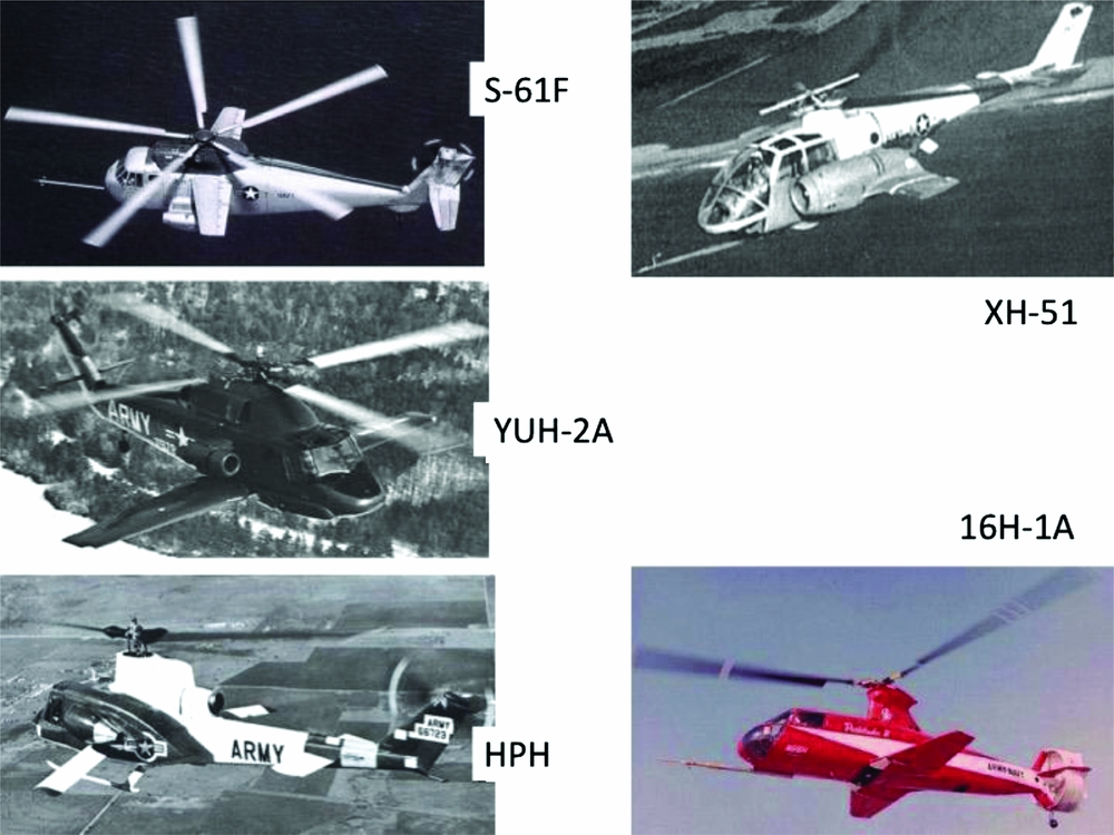
In the 1960s, four existing helicopters, shown in Fig. 2, were modified for compound research(Reference Dumond8). The Kaman YUH-2A was a modified Seasprite helicopter with an auxiliary wing and a single turbojet engine. It achieved a speed of 224 mph in 1965. The Sikorsky S-61F was developed from an S-61 Sea King fitted with an auxiliary wing and turbojet engines; it achieved 264 mph in 1965. Lockheed modified a four-bladed XH-51A rigid-rotor helicopter with stub wings and a single turbojet, and it achieved a speed of 302 mph in 1967. Several modified versions of the Bell UH-1 helicopter used wings and auxiliary turbojet engines; the two-bladed high-performance helicopter (HPH) reached a speed of 316 mph in 1969. The Piasecki 16H-1A experimental compound, also shown in Fig. 2, used a ducted propeller for yaw control and auxiliary propulsion, and achieved 225 mph in 1966.
Flight research compound test beds of the 1960s.
This flight research was significant in proving the basic feasibility of the compound helicopter – that a rotor could provide lift and be controlled at high advance ratios. However, the practicality, or usefulness, was far from proven. In addition to loads, dynamics and control issues, aerodynamic efficiency was disappointing, though hardly surprising, because these aircraft were not designed with optimised aerodynamics, propulsion, drive systems and flight controls.
Based on the needs of the Vietnam War, and undoubtedly on the success and potential of the 1960s compound research, the Army issued a solicitation in 1966 for an attack helicopter, the Advanced Aerial Fire Support System (AAFSS). With a speed requirement of 252 mph (220 kn), this was an important milestone in the history of the compound helicopter. Lockheed proposed a scaled-up compound version of the XH-51A with an auxiliary wing, a propeller for auxiliary propulsion and a tail rotor for anti-torque control(Reference Hewson9). Sikorsky proposed a compound helicopter with an auxiliary wing and a swivelling Rotoprop for both propulsion in high-speed flight and anti-torque control in hover and low-speed flight.
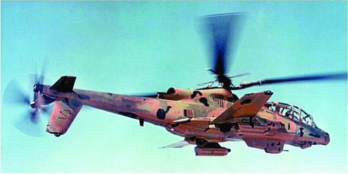
Lockheed was selected as the winner, and the first flight of the AH-56A Cheyenne occurred in 1967, followed by a production contract for 375 aircraft in 1968 (Fig. 3). However, the AH-56A development encountered rotor dynamics problems(Reference Prouty and Yackle10) that ultimately led to the loss of two prototype aircraft and cancellation of the production contract in 1969. Although inter-service rivalry over roles and missions contributed, technical difficulties were undeniably a key factor. Nevertheless, R&D support continued, and a new Advanced Mechanical Control System (AMCS) resolved the rotor's technical problems. In 1972, the AH-56A substantially demonstrated the original performance requirement of 220 kn, 1,063 nm un-refuelled range and a maximum speed of 253 mph (278 mph in a dive).
The Army Lockheed AH-56A Cheyenne compound helicopter.

The cancellation of the AH-56A was not the result of any basic deficiency of the compound concept. In contrast to the earlier flight research compounds, the AMCS Cheyenne was a considerable success, particularly because it was designed to meet operational military requirements.
Despite its belated success, the technical difficulties, cost overruns and programme cancellation had a profound and far-reaching impact on perceptions of compound helicopter viability. For the next four decades, aside from isolated exceptions, the technical community largely abandoned the compound helicopter, creating, in effect, a ‘Compound Gap’.
Exceptions included Sikorsky's XH-59A and the S-72 Rotor Systems Research Aircraft (RSRA). The XH-59A's advancing blade concept (ABC) used coaxial, hingeless, lift offset rotors to overcome retreating blade stall in high-speed flight and was tested from 1973 until 1980(Reference Burgess11). The basic helicopter achieved a maximum speed of 184 mph, and a compound version with twin turbojets reached 303 mph. Flight characteristics were impressive, but the XH-59A suffered from weight, vibration and high fuel consumption. The RSRA was a research vehicle designed to flight test experimental rotors rather than advance the compound concept itself. With a wing and auxiliary turbofan engines, the compound version first flew in 1978(Reference Robb5).
During the Compound Gap, little serious attention was devoted to compound technology. Eventually, however, interest in the compound slowly began to re-emerge. The Piasecki X-49 compound(Reference Hirschberg12), a modified SH-60 Seahawk with an auxiliary wing and a variable thrust ducted propeller (VTDP) for auxiliary propulsion and anti-torque control, is shown in Fig. 4. In 2007, the X-49A exceeded 160 kn in level flight and achieved 177 kn in a slight dive. The CarterCopter compound autogyro demonstrated slowed-rotor operation and potential improvements in aerodynamic efficiency in cruise(Reference Carter and Lewis13).
Newer compounds – Piasecki X-49A, Sikorsky X2, Airbus Helicopters X3, and Sikorsky S-97.
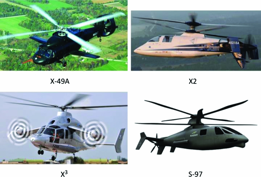
More recently, Sikorsky revisited the coaxial lift-offset compound and invested in a company-funded X2 Technology™ Demonstrator(Reference Walsh, Weiner, Arifian, Lawrence, Wilson, Millott and Blackwell14) designed to provide seamless transition from hover to high-speed flight without requiring vehicle conversion (Fig. 4). Incorporating advanced propulsion, flight control, aerodynamics and active vibration alleviation technology, the X2 largely overcame the limitations of the XH-59A. In July 2010, it achieved an unofficial speed record of 253 kn (291 mph). Sikorsky invested further in this technology and developed the S-97 Raider™ scout helicopter now entering flight test.
Similarly, Airbus Helicopters developed the X3 company-funded demonstrator (Fig. 4) with modified components based on the AS365 N3 airframe, the EC-155 rotor and the EC-175 main gearbox. Two auxiliary propellers mounted on the auxiliary wing provide cruise propulsion and anti-torque control in hover(Reference Hirschberg12).
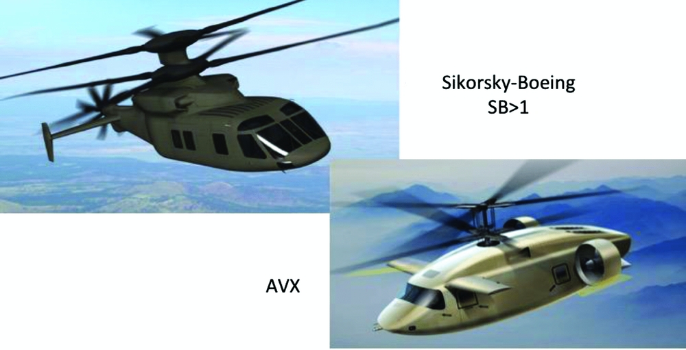
In 2014, the U.S. Army embarked on the Joint Multi-Role (JMR) technology demonstrator programme(Reference Hirschberg15) and is supporting aircraft and technology development. Sikorsky-Boeing is developing a coaxial lift-offset compound for the JMR-TD, the SB>1 Defiant™, and AVX is developing technology for a coaxial compound with auxiliary wings and propulsion (Fig. 5). It is somewhat ironic to compare the 2014 JMR and 1964 AAFSS requirements of 220 versus 230 kn – a gain of 10 kn in 50 years.
Sikorsky-Boeing SB>1 and AVX JMR compounds.
3.2 Tiltrotors
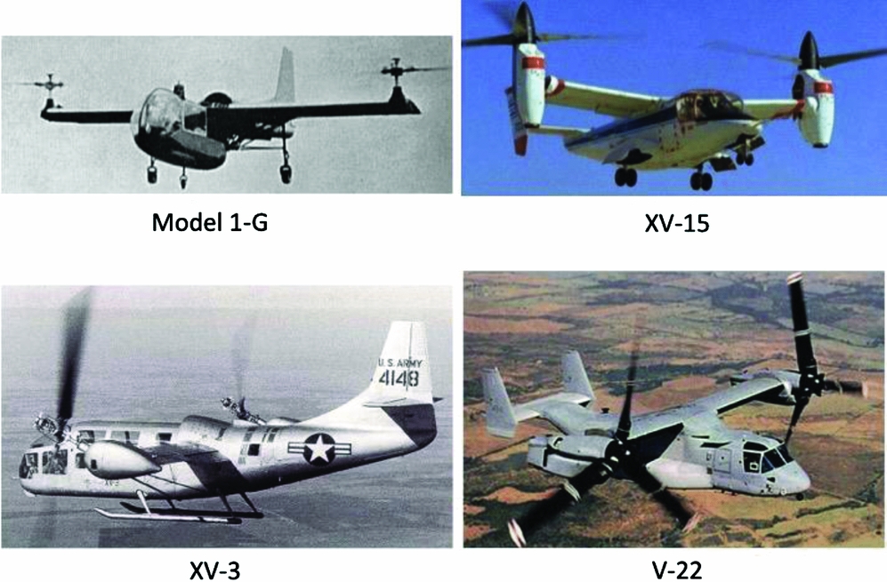
The tiltrotor (Fig. 6) was another approach to overcome the helicopter's limitations in forward flight(Reference Maisel, Guilianetti and Dugan16). The basic concept was to transform the helicopter into an aircraft by tilting the rotor 90 degrees to become a propeller and adding a wing to replace the rotor lift. Unlike the compound, early development of the tiltrotor was fraught with difficulty. In the late 1940s, the Transcendental Model 1-G progressed through nearly complete conversions to aircraft mode flight, however, the aircraft crashed in 1955.
Tiltrotor aircraft development, 1947–2015, a rotorcraft success story.

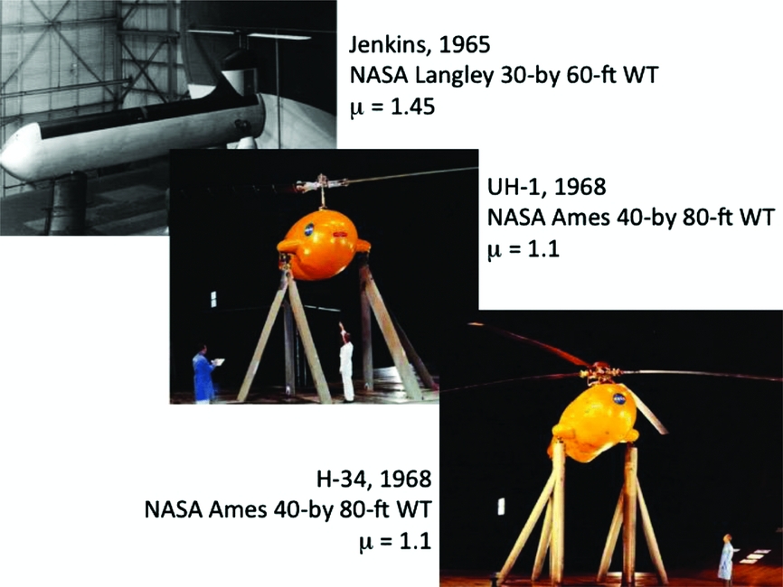
As part of the same Army and Air Force Convertiplane Program that sponsored the XV-1, Bell Aircraft initiated the XV-3. Hover flights began in 1955. However, significant rotor dynamics and proprotor whirl flutter problems caused several ground and flight-test accidents, and a crash in 1957. After modifying the three-blade articulated rotors to two-blade teetering rotors, the first full aircraft mode conversion was accomplished in 1958, although flying qualities deficiencies were encountered. Flight testing also revealed rotor limit cycles that were subsequently observed during 1962 wind-tunnel testing. Extensive analytical investigations of proprotor dynamics and whirl flutter aeroelasticity were initiated and eventually validated by Hall and Edenborough with small-scale experimental model testing(Reference Lynn4). Full-scale wind-tunnel testing in 1966 further confirmed the analysis and also replicated prior flight-test observations.
Success prompted the initiation of the NASA/Army Bell XV-15 tiltrotor research aircraft programme in 1973. Full-scale testing of competing Bell and Boeing semi-span proprotor-nacelle-wing designs was conducted, and analytical methods continued to mature(Reference Johnson17). Bell won the competition for the XV-15 proof-of-concept demonstrator. The first hover flights occurred in 1977, and the first full conversion to airplane mode occurred in 1979. The technical difficulties of proprotor whirl flutter were fully overcome, and the high-speed airplane-mode flight performance met all expectations, achieving 345 mph in level flight in 1980. The success of the XV-15 convincingly proved the viability of the tiltrotor concept.
The XV-15 led directly to the development of the Bell-Boeing V-22 Osprey tiltrotor for the Marines beginning in 1986(Reference Lynn4), and development of the Bell-Agusta Westland AW609 commercial tiltrotor is presently underway.
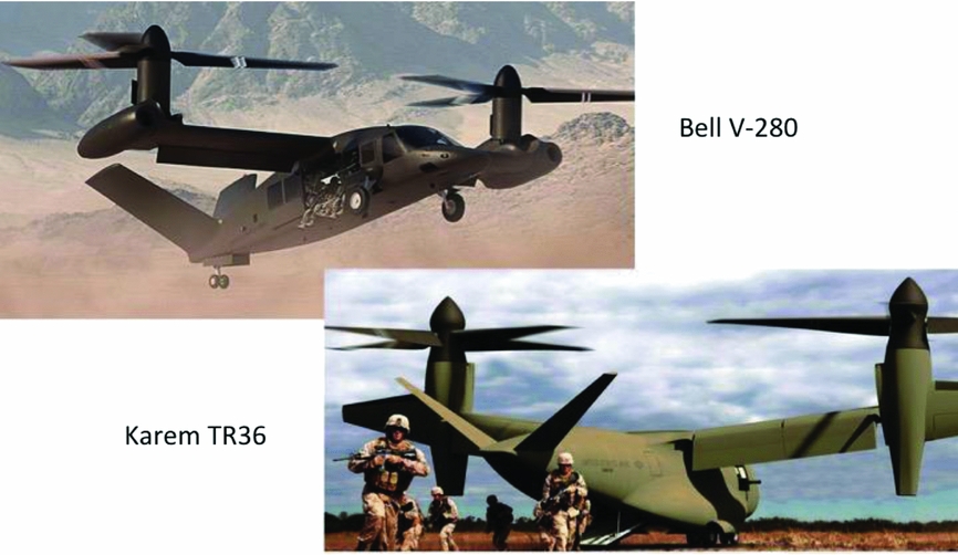
More recently, as part of the Army's JMR technology demonstrator programme(Reference Hirschberg15), Bell is developing the V-280 Valor and Karem Aircraft is developing technology for its TR36 tiltrotor, both shown in Fig. 7.
Bell V-280 Valor and Karem JMR tiltrotors.
3.3 Hingeless and bearingless rotors
An important part of the evolution of rotorcraft technology deals with the development of hingeless and bearingless rotor technology that is relevant for future advanced rotorcraft for two reasons: (1) the history of the hingeless rotor is a reminder that new rotor concepts invariably present new aeroelastic stability risks, and (2) the basic hingeless rotor configuration offers advantages for operation at a high advance ratio that make it a leading candidate for compound rotorcraft.
An overview of early hingeless and bearingless rotor development is included in Refs 18 and 19. From the beginning, helicopter inventors and developers conceived of a nearly endless variety of ways to attach rotor blades to the hub and to change blade pitch. The fully articulated rotor hub became one of the most common types, even though the flap, lag, pitch hinges, bearings and lag dampers contributed to complexity, weight, drag and maintenance. In the 1960s, the ‘rigid rotor’ emerged with the blades attached directly (cantilevered) to the rotor hub without flap and lag hinges, thus the term ‘hingeless’. Stiff- or soft-inplane types were identified by whether the first inplane mode frequency was greater or less than 1/rev, respectively. Stiff-inplane rotors avoided ground or air resonance instability, obviating lead-lag dampers, but tended to be heavier than soft-inplane rotors. Typical examples included the soft-inplane MBB BO-105 and Westland WG-13 Lynx, and the stiff-inplane Lockheed XH-51.
The Lockheed Cheyenne described earlier emerged from the highly successful XH-51 (and predecessor CL-475). Significantly larger and with a different design for the hingeless hub, it unfortunately encountered a number of vexing aeroelastic stability issues(Reference Johnston and Cook20) not seen on the XH-51. As noted previously, these contributed substantially to the cancellation of the programme. The Frontier Aircraft unmanned A160(Reference Adriaans, Cribbs, Ingram and Gupta21) employs a stiff-inplane hingeless main rotor that can be considered a successful contemporary example of the stiff-inplane hingeless rotor.
Although the Cheyenne's fallout adversely impacted the compound helicopter, interest in the hingeless rotor remained high, and Boeing used a soft-inplane rotor for its YUH-61A Utility Tactical Transport Aircraft System (UTTAS) entry. The impetus to simplify conventional rotors continued. The notion of hingeless rotor ‘simplicity’ was viewed as a means to reduce the stigma of helicopter complexity and unreliability—and was sometimes elevated to the status of a virtue. This led to the bearingless rotor that eliminated the pitch bearing to attain the ‘ultimate’ in rotor simplicity. Army R&D supported the Lockheed XH-51 (matched-stiffness) and Boeing BO-105 BMR—both soft-inplane bearingless (and damperless) rotor programmes. Sikorsky and Boeing R&D led to bearingless tail rotors on both UTTAS prototypes, the YUH-60A and YUH-61A(Reference Ormiston18).
Another advanced rotor research, development, testing, and evaluation (RDT&E) programme, the Army/NASA Integrated Technology Rotor/Flight Research Rotor (ITR/FRR) sought to push this technology further along with improved rotor aerodynamic performance as well. The programme did not progress beyond the preliminary design and small-scale test phase, but it did advance bearingless rotor technology(Reference Bousman, Ormiston and Mirick22) and led to the Hughes Advanced Rotor Program (HARP) and MD-900 bearingless rotors. Bell also developed the Model 680(Reference Kernstock23) at this time. These developments effectively defined the ‘accepted’ bearingless rotor configuration comprising an external torque tube for pitch control and an elastomeric snubber bearing for air/ground resonance stability as embodied in the MBB BO-108, the Sikorsky-Boeing RAH-66 Comanche(Reference Panda, Mychalowycz, Kothmann and Blackwell24), the Bell UH-1Y/AH-1Z and the Airbus Helicopters EC-135.
It is somewhat ironic that the bearingless rotor never emerged as the ultimate rotor configuration in terms of simplicity, performance and weight, and it is found on only a small fraction of production helicopters. In fact, current bearingless rotors typically include a torque tube of relatively high frontal area and a lead-lag damper. And the analytically challenging Comanche regressing lag mode (RLM) air resonance stability issue(Reference Panda, Mychalowycz, Kothmann and Blackwell24) illustrates that the mechanical simplicity of the bearingless rotor is accompanied, conversely, by more complex aeroelastic behaviour.
3.4 Rotorcraft development – aeroelastic risk
It is abundantly clear from rotorcraft development history that the dynamics and aeroelasticity discipline is both a key enabler – solution of the early tiltrotor problems paved the way to concept feasibility – and a key risk area – the issues encountered during the Cheyenne programme helped to derail that programme. It is clear that unexpected dynamics and aeroelastic issues represent a significant potential risk in any development programme, especially for advanced rotorcraft. Because the impetus for new concepts arises from a focus on aerodynamic performance opportunities, the aeroelastic implications are typically overlooked. Simply as a reminder that aeroelastic issues are a fact of life and should not be forgotten, a number of the more consequential instances are summarised in Table 1.
Significant aeroelastic stability events

3.5 The Compound Gap – what happened?
The decades-long hiatus in compound developments following the accomplishments of the 1960s and the success of the AH-56A Cheyenne raises an obvious question: Who, or what, killed the compound? One answer might be that the disadvantages simply outweighed the advantages; however, this is too simplistic. A more plausible explanation is less obvious. More likely, the coincidental timing, and the relative fortunes of compound and tiltrotor developments – specifically, the Cheyenne and the XV-15 – were key to determining subsequent outcomes in high-speed rotorcraft development.
As noted earlier, the research compounds showed considerable progress in the early stages and were sufficiently promising to give rise to the Army's AAFSS programme. The subsequent technical problems effectively ended that programme, but, more significantly, the Cheyenne experience was a serious setback for the compound helicopter concept itself.
On the other hand, the fortunes of the tiltrotor followed a different path. In the early stages, it encountered significant aeroelastic problems. However, after gradual progress of analytical and experimental R&D, the XV-3's technical issues were overcome. This led directly to the NASA/Army Bell XV-15, which made steady progress and became a resounding success. Importantly, this success occurred shortly after the Cheyenne programme ended.
The success of the XV-15, in stark contrast to the setbacks of the AH-56A, amounted to a direct reversal in the fortunes of the compound. The Army abandoned the high-speed requirement, revised its AAFSS requirement into the Advanced Attack Helicopter (AAH) mission, and solidified its focus on conventional low-speed rotorcraft and missions (AH-64 Apache).
All of this undoubtedly led to the perception that the tiltrotor was the preferred, if not the only, way to achieve efficient, high-speed rotorcraft performance. The conventional helicopter remained the accepted low-speed solution, and the compound disappeared from thoughts about advanced rotorcraft R&D. Over subsequent decades, this view became entrenched as conventional wisdom, and the concept of the high-speed compound effectively died.
The current status quo of tiltrotor pre-eminence is largely the result of a quirk of history that faded from consciousness and was quickly forgotten. Ironically, the Cheyenne's problems were largely unrelated to any real compound issues. Moreover, at one time, it was the tiltrotor that was thought to be dead. Indeed, R.R. Lynn's 1992 Nikolsky Lecture, “The Rebirth of the Tiltrotor”, recounted this perception and how it was reversed(Reference Lynn4).
History reminds us that aircraft development is not a wholly rational process. There is much chance and serendipity in RDT&E, and today's reality could easily have been quite different. Had the AH-56A not encountered its technical problems, 375 compound helicopters might well be in operational use today.
So, the Compound Gap – abandonment of compound R&D for nearly three decades – is likely attributable to the dramatic reversal of fortunes of the Cheyenne and XV-15 over a few short years in rotorcraft history. Re-emergence of interest and a reconsideration of the compound's potential have begun. Its feasibility is evident, but its practicality, or whether it can attain sufficient aerodynamic efficiency, is not yet known.
4.0 RECONSIDERING THE COMPOUND
During the Compound Gap since the end of the early 1970s, there has been very little development of compound-specific technology, and there is little up-to-date information available about the true performance potential of a ‘modern’ compound. As part of the re-emergence of interest, a number of mission design studies have been conducted within the past ten years – based on projections of modern technology – that are beginning to suggest the viability of a modern compound. It is appropriate to briefly review some of the most relevant results.
4.1 Compound and tiltrotor comparison
As an introduction, the performance of a simple compound is compared to an equivalent tiltrotor in cruise flight – based on the essential measure of aerodynamic efficiency, the effective lift-to-drag ratio, L/De. Very simple modelling strips the comparison down to bare essentials and highlights the principal factors that distinguish the performance capabilities of these rotorcraft types. The two aircraft have the same gross weight, wing area, wingspan, disk loading and fuselage parasite drag area. Only the fuselage, wing and rotor/proprotor aerodynamics are modeled. The rotor-induced inflow is taken as ideal momentum theory and rotor/wing interference is ignored. The wing lift share in cruise is 100% and the wing download in hover is ignored, so hover performance is identical. The compound auxiliary propeller losses, proprotor nacelle drag, and compressibility effects are ignored. Both rotors are slowed linearly with airspeed down to 50% of hover tip speed for the tiltrotor and 20% for the compound.
The only significant differences between the two aircraft are the edgewise rotor and proprotor profile power and the rotor hub parasite drag of the compound. Here, the hub drag is defined in terms of the rotor hub flat plate parasite drag area, fe, the vehicle gross weight, GW, and the hub drag factor Kfe.
 $$\begin{equation}
f_e = K_{fe} \left( {{\raise0.7ex\hbox{${GW}$} \!\mathord{\left/
{\vphantom {{GW} {1000}}}\right.\kern-\nulldelimiterspace}
\!\lower0.7ex\hbox{${1000}$}}} \right)^{\frac{2}{3}}
\end{equation}$$
$$\begin{equation}
f_e = K_{fe} \left( {{\raise0.7ex\hbox{${GW}$} \!\mathord{\left/
{\vphantom {{GW} {1000}}}\right.\kern-\nulldelimiterspace}
\!\lower0.7ex\hbox{${1000}$}}} \right)^{\frac{2}{3}}
\end{equation}$$
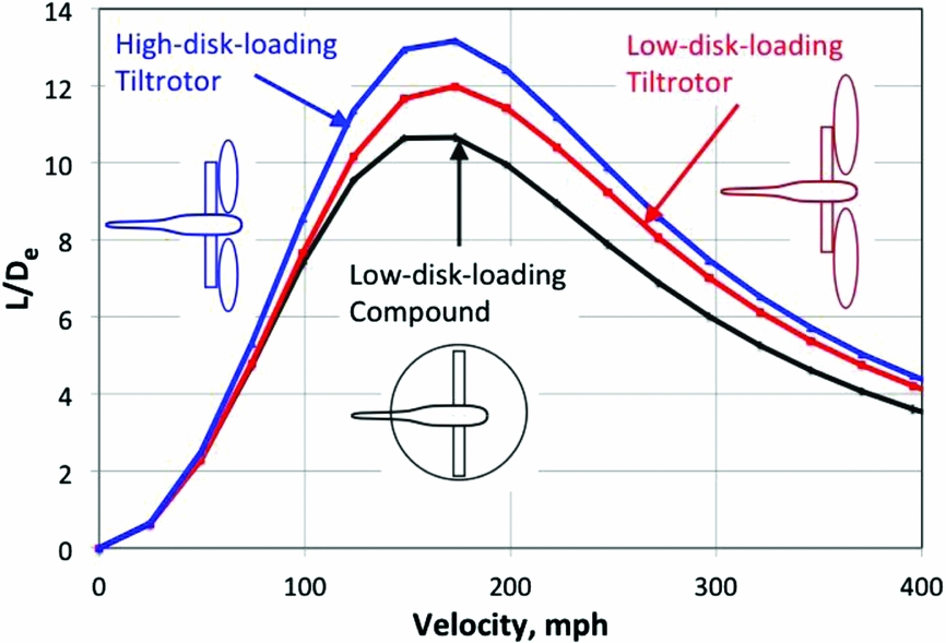
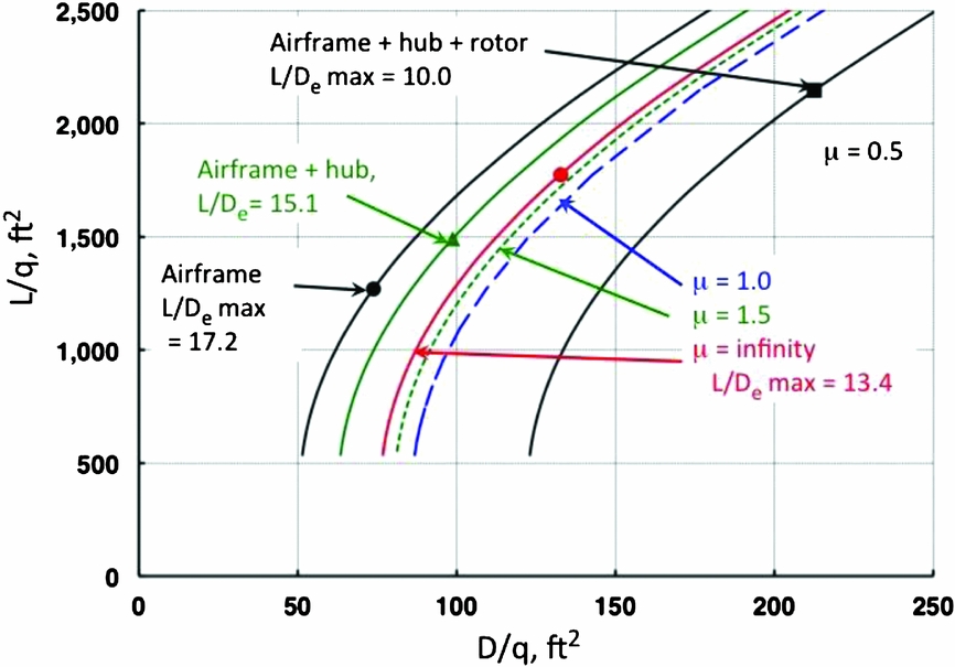
For this comparison, Kfe = 0.28, which represents a very low drag hub. As discussed later in Part 3, the drag factor for the best current rotor hubs is about 0.50. The physical and aerodynamic properties of the two aircraft are listed in Table 2. Note that beyond the basic comparison, an additional case for a high-disk-loading tiltrotor is included where the disk loading is roughly doubled.
Model parameters for simple compound and tiltrotor aerodynamic comparison

The analysis results are presented in Fig. 8. With the low disk loading, the maximum L/De of the compound is very close to that of the tiltrotor because of the low hub drag chosen for the compound. If the two aircraft have the same installed power, equal to the hover power, then the maximum speeds (at sea-level standard conditions) for the compound and the tiltrotor are 247 and 262 mph, respectively – a difference of only 15 mph! For the high-disk-loading tiltrotor, the maximum L/De is increased because the smaller proprotor decreases the profile power. With the higher power needed to hover from the higher disk loading, the maximum speed becomes 310 mph. Of course, with higher disk loading, the L/De and maximum speed of the compound would increase as well. Further comparison results are available in Ref. 25.
Simple performance analysis – for equal disk loading, an advanced, low-drag compound can approach tiltrotor aerodynamic efficiency(Reference Ormiston25).

The conclusions drawn from this comparison are that (1) an advanced compound with a low-drag fuselage and a very-low-drag rotor hub can approach the efficiency of a tiltrotor of the same disk loading, and (2) the high-speed capability of the tiltrotor derives in part from the power needed to hover with high-disk loading. So, the message is that attractive performance is possible for the compound, but it can be realised only if the drag is reduced to a very low level.
4.2 NASA and Army mission design studies
A number of mission design studies have been conducted by NASA and the Army in the last 10 years to assess the performance capabilities of helicopters, tiltrotors and several compound configurations, for a wide variety of civil and military mission scenarios. The objectives included exploring potential mission performance in terms of technology factors, identifying critical technologies for R&D planning, determining military mission performance and identifying optimum configurations for specific mission applications. Taken together, these studies offer a qualitative sense of the performance and overall feasibility of advanced rotorcraft according to modern design methodology and reasonable assumptions for the state of the art in relevant technical disciplines.
An overview of results from seven selected studies(Reference Johnson, Yamauchi and Watts26-32) is shown in Fig. 9. Study dates, mission, design gross weight, disk loading, maximum and cruise velocity, and L/De are included. The hub drag parameter, Kfe, defined earlier in Equation (1), is also included for compound helicopters. It should be noted that direct comparisons of these results are not possible because the missions, modeling assumptions, and other factors vary from study to study. However, the purpose is to assess the results in aggregate to infer the general performance potential of the compound.
Recent NASA and Army mission design studies point to compound potential.

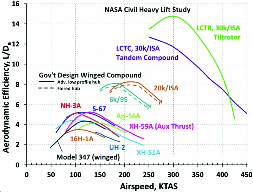
The principal results of interest are the maximum or cruise-speed capabilities and the aerodynamic efficiencies, or max L/De, at a specified cruise speed. Overall, both the flight speeds and the L/De values for the modern compounds are far higher than current conventional helicopters. And the L/De values are well above the capabilities of the experimental compounds of the 1960s. Particularly interesting are the aircraft designed for the 2006 NASA civil heavy lift mission study(Reference Johnson, Yamauchi and Watts26). This design mission called for a 120-passenger short-haul transport with a cruise speed of 350 kn at 30,000 ft and a range of 1200 nm. The study investigated a tiltrotor and two compound configurations. The large civil tiltrotor (LCTR) showed higher L/De at cruise than the large civil tandem compound (LCTC) and performed the mission at lower gross weight with less fuel consumed, but the compound showed impressive performance and a high cruise L/De. As in the simple comparison shown in Fig. 9, the NASA/Army mission studies assumed very low levels of hub drag for the compound helicopter, with Kfe generally in the range of 0.35 to 0.5.
Additional results from two of the studies are presented in Fig. 10, in which aerodynamic efficiency, L/De, is plotted as a function of flight speed. Estimates of L/De obtained from the 1960s experimental compound flight tests are also included for comparison. The NASA civil heavy lift mission study results are even more impressive in direct comparison with the compound flight-test results. The government design winged compound study for a representative Army mission in support of the JMR programme(32), with an L/De above 8.0, also compares well with the flight-test results.
Comparison of aerodynamic efficiency from NASA and Army studies with 1960s research compounds, L/De versus airspeed.

Again, the simple comparison of Fig. 8 and the results of the NASA/Army mission design studies suggest that, while the compound helicopter may not be the optimum configuration for high-speed or long-range missions, it does have the potential, subject to certain advances in hub drag technology, for far higher speeds and performance than the conventional helicopter – and ‘not far’ from the tiltrotor.
5.0 RATIONALE FOR THE COMPOUND
Given the accomplishments of the 1960s compounds and the Cheyenne, the encouraging results from the mission design studies, and the accomplishments of the Sikorsky X2 and Airbus Helicopters X3, there seems to be a rationale emerging for both civil and military applications of the compound helicopter. The following sections address topics that provide additional support for this rationale.
5.1 The complexity factor
The mechanical complexity of the helicopter rotor, swashplate controls, anti-torque system, transmission and drive train significantly reduces reliability, availability and maintainability, which, in turn, impact mission effectiveness and operating cost. Considerable R&D has aimed to improve and simplify the helicopter; indeed, one of the drivers for hingeless and bearingless rotor technology was the search for less complexity and lower parts count. Acceptance of new technologies ultimately rests on a cost/benefit balance. In the case of the tiltrotor, the benefits for high-speed, long-range missions offset the cost of increased complexity. Whittle cited these trade-offs for the V-22 Osprey in Ref. 33, but noted that a larger fleet size was needed to offset reduced readiness caused by maintenance requirements.
In weighing the relative benefits of future compounds, the impact of complexity should be taken into account. This presents a dilemma for decision makers choosing a vehicle type for a future programme: How can the influence of complexity be taken into account when it is unclear how to determine its impact?
Typically, when mission design studies are performed to evaluate competing configurations, engineering analyses – based on relatively mature and reliable physics-based methods – are employed to determine mission performance metrics, weight and fuel required(Reference Sinsay34). Life-cycle costs are more difficult to determine, but relatively reasonable estimates can be made. In marked contrast, accounting for the impact of complexity is difficult, if not impossible.
Beyond the difficulty of quantifying the impact of complexity is the question of how to define it in the first place. Some possible quantitative measures might be, for example, parts count, fraction of empty weight comprised of moving parts (degree of variable geometry), or the number of drive train and tilting components (rotors, shafting, transmissions and nacelles).
Simply to illustrate the concept of such a measure, consider a notional ‘Complexity Index’, depicted in Fig. 11, to distinguish the complexity of different rotorcraft types. First, simply take the complexity of a helicopter to be 1.0. An airplane with fixed wings might be 0.6, and a glider with no moving parts could be 0.2. A compound helicopter, with auxiliary wing, propulsion, rotor and anti-torque components, might be 1.2. The tiltrotor, with variable geometry nacelles, drive train and tilting rotors, might be 1.5. These values are entirely hypothetical but represent something that is very real even without the ability to meaningfully quantify it.
A notional complexity index for several aircraft types. Complexity is difficult to evaluate but should nevertheless be included in aircraft selection.

The bottom line is that decision-making should take into account all of the important attributes of competing configurations. The impact of some attributes may be difficult to quantify, but that is not a reason to ignore any of them.
5.2 The mission gap
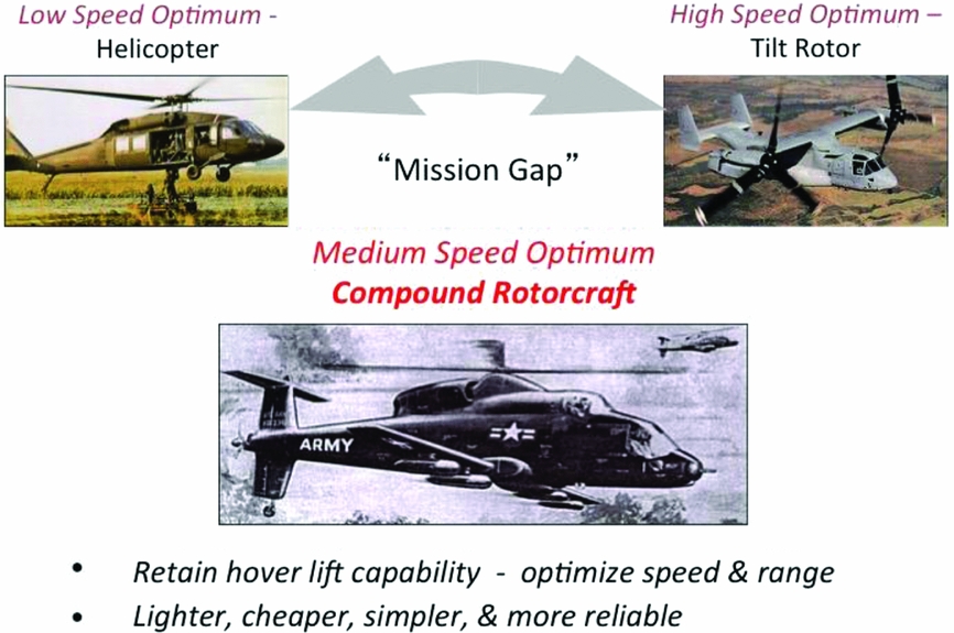
The bipolar spectrum of operational rotorcraft – from helicopter to tiltrotor – effectively constitutes a ‘mission gap’. This is depicted in Fig. 12. The Army places particular emphasis on efficient vertical lift and agility for hover and short-range missions, traits that favour the low-disk-loading helicopter. If the operator desires more speed and range but cannot sacrifice efficient low-speed operation, the question becomes, is there an alternative choice somewhere between the helicopter and the tiltrotor? Because the pure helicopter is optimum for low-speed operation and the tiltrotor is optimum for high-speed missions, it would seem, intuitively, that a low-disk-loading compound helicopter would be best to fill the mission gap. Given that a range of such missions may exist, it is reasonable to assume that the compound would be preferable to the tiltrotor for many of them.
An intuitive view: the mission gap, a compound opportunity for intermediate speed missions.

5.3 R&D opportunities
The options for investing in advanced rotorcraft research and how to maximise the return on that investment are considered next. Which rotorcraft platform is most deserving of R&D investment is also discussed.
The conventional helicopter is the mainstay of low-disk-loading VTOL aircraft. There will always be needs and opportunities for R&D to push back the long-standing barriers of stall and compressibility. But because these are nearly insurmountable, the mission performance of conventional helicopters has essentially plateaued, and future leaps in capability are unlikely.
The tiltrotor concept is now well established as the accepted choice to meet ‘high-speed’ mission requirements. The technology is relatively well understood and there are few fundamental barriers. The inherent design limitations are determined by the choice of disk loading and the trade-offs between rotor hover performance and cruise efficiency.
The compound appears to be feasible but the potential for high aerodynamic efficiency is unproven. Owing to the Compound Gap, very little R&D has addressed the specific opportunities and technical issues of the compound. Promising mission design studies were based on expectations of reduced rotor and hub drag from future research, so it would seem that the compound would benefit substantially from modern technology and targeted research.
Considering all three rotorcraft types, there are more compelling opportunities and payoffs for compound helicopter R&D than for helicopters and tiltrotors. Along with the need for compound R&D, such an investment would be the most promising way to revitalise research for advanced rotorcraft.
5.4 Compound – re-imagined
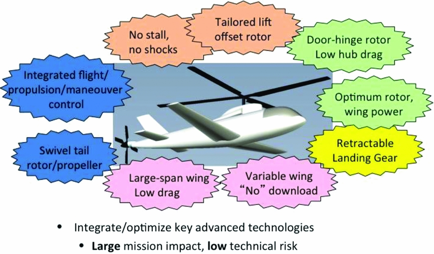
If one accepts that the compound is indeed a reasonable option to fill the mission gap, then it is worth identifying and highlighting the likely features and technologies that should be pursued to realise the full potential of an advanced compound.
Such a notional compound configuration is depicted in Fig. 13. An auxiliary wing comparable in span to the rotor diameter off-loads rotor lift in cruise and minimises induced drag for high cruise efficiency. The blade planform, twist and aerofoils are designed and tailored to balance optimum hover figure of merit and minimum power in forward flight. The rotor speed is significantly reduced to minimise rotor profile power in cruise. The fuselage is designed for minimum drag, and new technology substantially reduces hub drag. A variable incidence wing minimises hover download and optimises rotor/wing lift sharing to minimise drag in cruise. An added benefit is optional field removal of the wing to maximise payload for low-speed missions. A swivelling auxiliary propeller provides propulsive force and hover anti-torque and yaw control. Fully integrated advanced flight control technology is essential to optimise aerodynamic performance and provide control, manoeuvrability and agility in all flight regimes while ensuring flutter suppression and structural load control.
The compound re-imagined. Technologies to be pursued to achieve greatest mission performance.

6.0 PART 2 – KEY AEROMECHANICS RESEARCH
Two goals of this paper are to reinvigorate fundamental and applied research in rotorcraft dynamics and aeroelasticity, and to advance capabilities in prediction methodology. Therefore, it is important to review aeromechanics research in these areas to provide a framework, or context, for potential new research opportunities. Furthermore, reviewing the techniques and approaches that led to success will suggest ways that should help to plan and execute future research. Although some of the aeromechanics research in Part 2 focuses on activities of the U.S. Army Aeroflightdynamics Directorate (AFDD), it must be emphasised that many other organisations made essential contributions in these areas.
7.0 AEROELASTIC STABILITY RESEARCH AT AFDD
In 1969, the impetus for aeroelastic stability research was derived from broad general interest in hingeless and bearingless rotors and, more particularly, the Cheyenne's technical challenges that arose from hingeless rotor dynamics and aeroelasticity. Unlike the relatively simple aeroelastic stability behaviour of the articulated rotor, the hingeless rotor was considerably more complex aeroelastically. The lack of experience and fundamental understanding of this behaviour contributed to the development problems of hingeless rotors and resulted in AFDD research efforts into dynamics and aeroelasticity of hingeless rotors in the early 1970s, summarised in Refs 18 and 19.
The AFDD research objectives were to (1) develop fundamental understanding of relevant phenomena, (2) develop theory and analyses to predict hingeless rotor aeroelastic and dynamic characteristics and (3) experimentally validate these capabilities. Synergy among these objectives enabled theory development to be included in the design of the experiments, and differences between predictions and measurements to be used to improve the analyses. The multi-layered complexity of rotorcraft called for a reductionist approach to break up the problem into a series of simpler problems.
7.1 Flap-lag stability – the first investigation
The first investigation of hingeless rotor aeroelastic stability was limited to a single, isolated rotor blade in hover and encompassed a number of analytical and experimental studies.
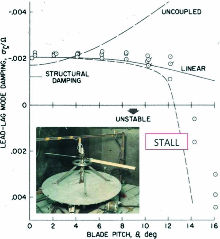
Motivations for the initial flap-lag studies included the Cheyenne experience as well as an ongoing theoretical controversy at the time. MI Young(Reference Young35) had suggested that hingeless rotors could experience non-linear flap and lead-lag aeroelastic instability not previously envisioned. Hohenemser and Heaton essentially put the matter to rest in Ref. 36. However, the author noted an error in the linearisation process and showed that flap-lag coupling could lead to weak flap-lag instability(Reference Ormiston and Hodges37). A simple experiment was devised to confirm this result, and measurements of the lead-lag damping clearly showed instability arising from the flap-lag coupling – a significant difference from the case without the flap-lag coupling terms (Fig. 14).
The first AFDD aeroelastic hover experiment measured lead-lag damping versus collective pitch and confirmed early flap-lag stability theory(Reference Ormiston and Bousman38).

However, at high collective pitch, the results unexpectedly departed from the linearised analysis(Reference Ormiston and Bousman38). This resulted from the effects of blade stall that reduced the damping of the blade flapping motion and, owing to coupling of the flap and lag degrees of freedom (DOFs), produced a stronger flap-lag instability. Several analyses and experiments were performed to unravel this phenomenon and led to a linearised aerofoil stall model that was quite effective in representing “flap-lag stall instability”, as shown in Fig. 14.
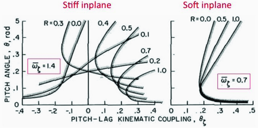
Another example illustrates how analysis alone can be used to explore aeroelastic phenomena, provide fundamental understanding and point to the practical consequences of choosing one rotor type over another. During the 1960s, the benefits of soft-inplane versus stiff-inplane hingeless rotors were a subject of considerable debate. As noted earlier, soft-inplane rotors were presumed lower weight while stiff-inplane rotors avoided ground and air resonance. It was also known that kinematic pitch-lag coupling could be very destabilising for articulated rotors, but the problem could be avoided by proper design of the control system. When the AFDD analytical models combined flap-lag structural coupling with pitch-lag coupling, it was discovered in Ref. 37 that the stiff-inplane hingeless rotor was susceptible to a wide range of flap-lag instabilities depending on the particular design parameters of the rotor. For example, stability boundaries are shown as a function of pitch-lag coupling for representative soft- and stiff-inplane rotors in Fig. 15. The stiff-inplane rotor shows broad sensitivity to the structural coupling parameter, R. Conversely, the soft-inplane rotor was much less sensitive and flap-lag instability was relatively easy to avoid. The potential susceptibility of the stiff-inplane hingeless rotor to aeroelastic phenomena was not known at the time. Not surprisingly, the AFDD results were of considerable interest to Lockheed engineers who had struggled with Cheyenne issues in flight test.
Example of basic research leading to practical insights for rotor design and evaluation(Reference Ormiston and Hodges37).
7.2 Experimental research (1970 – 1990)
Many studies followed the productive flap-lag stability investigations. Ultimately, the AFDD dynamics and aeroelasticity research encompassed hingeless rotor aeroelastic stability, non-linear beam theory, hingeless rotor response, Floquet theory, bearingless rotors and dynamic inflow. Portions of this work were the subject of the 28th and 34th Nikolsky Lectures by Peters and Hodges(Reference Peters39,Reference Hodges40) . The experimental investigations increased in scope and complexity to validate the correspondingly complex analyses. The model fabrication, experimental techniques, instrumentation and data analysis were continuously refined. The goal was to ensure the highest-quality data and the most complete database possible.
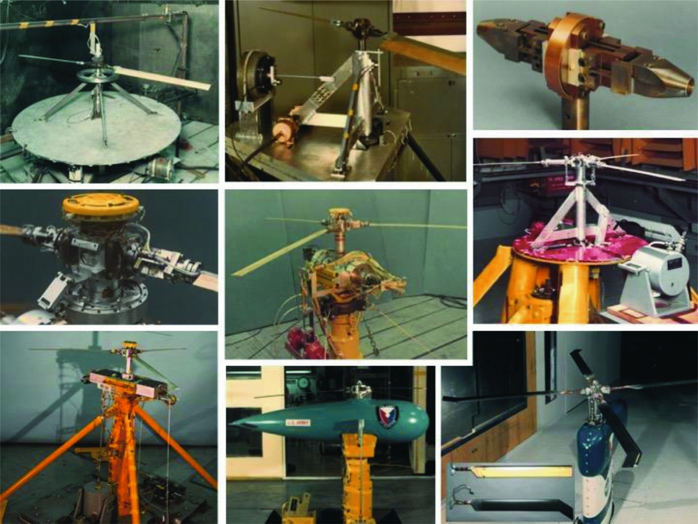
A portion of the experimental models used in these investigations is shown in Fig. 16 in order to convey the wide scope of this research. These included isolated rotors (fixed hub) with spring-restrained (flexure hinges) rigid blades and torsionally flexible elastic blades. The effects of various elastic and kinematic couplings for blade bending and torsion motions were explored, and geometric parameters such as precone, droop and torsion frequency were varied parametrically.
A selection of AFDD aeroelastic stability models representing numerous investigations over a 20-year span(Reference Ormiston18,Reference Ormiston, Warmbrodt, Hodges and Peters19) .

Experiments were conducted to explore the effects of coupling between blade motions in the rotating system and rotor hub motions in the fixed (non-rotating) system. Soft-inplane ground and air resonance phenomena, unsteady wake dynamic inflow and aeroelastic couplings for ground and air resonance were investigated. Bearingless rotor models were tested to evaluate emerging AFDD analytical methods.
Forward flight investigations were carried out in the AFDD 7 ft by 10 ft wind tunnel for isolated rotors with torsionally rigid elastic blades, as well as the advanced dynamic model (ADM) with straight and swept-tip torsionally flexible blades operating at full-scale tip speeds(Reference Maier and Abrego41).
The AFDD experimental research was based on a rigorous approach that evolved over time and was essential to its success. It is suggested that the basic principles be adopted for future R&D investigations.
1. Design models to validate analysis. Experimental models were specifically tailored for the analytical model. If the analysis did not include certain degrees of freedom or geometric features, models were designed accordingly. This ensured maximum compatibility for subsequent comparisons.
2. Prioritise accuracy of the measured data. This meant minimising flexibility in mechanical joints and eliminating non-linear friction by using flexures in place of ball bearings or rod-end bearings.
3. Ensure well-defined physical properties. It is critical to accurately determine geometric, mass and stiffness properties for meaningful comparison of predictions and data. Models were specifically designed to facilitate property measurements in the laboratory.
4. Eliminate non-essential features. It is important to simplify the model to eliminate non-essential features. In other words, simple models often provide more effective analytical validation than more complete or complex models.
5. Finally, repeat experiments when necessary. Exploring the unknown is not schedule driven. Experimental hardware and techniques need to be improved to resolve problems. Invariably, most experiments were done twice – first to learn how, then to do it right.
7.3 Aeroelastic stability – impact and decline
Analytical and experimental research in aeroelastic stability accelerated continuously at AFDD from the late 1960s through the late 1990s. The results of this research broadened the rotorcraft dynamics and aeroelasticity technology base considerably. During this time, extensive, high-quality experimental databases were accumulated that were invaluable for testing, debugging and validating aeromechanics prediction methods(Reference Bousman42,Reference Bousman43) .
The experimental work at AFDD plateaued in the early 1990s for multiple reasons including shifting priorities, organisational changes, resource requirements and the growing complexity of the experimental tasks. The net result was a decline in the vitality of research that should be of concern for future rotorcraft technology.
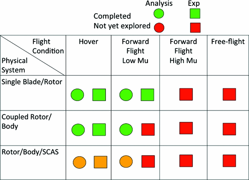
A qualitative illustration of this is provided by the matrix in Fig. 17, which classifies rotorcraft aeroelasticity topics according to the physical scope of the problem (part vs. whole) and operating condition (hover vs. forward flight). The individual matrix elements identify analytical and experimental topics that are highlighted in terms of their ‘degree of completion’. Topics that have received a reasonable amount of attention are colour-coded green, and areas that have received little or no attention are yellow or red. Many of the simpler problems have been investigated; many of the more complex and difficult topics have not, and these topics are the ones that are most relevant to future advanced rotorcraft.
Aeroelastic research topics organised in matrix form and depicting status of research for individual topics. Many topics have not been addressed.
History has shown that fundamental knowledge, analytical tools and the skills of researchers and designers must continue to be refined if future development programmes are to produce capable rotorcraft with acceptable development cost and risk. Therefore, the message is clear: research in the challenging areas of rotorcraft aeroelastic stability cannot be neglected and should be resumed and revitalised.
8.0 ROTORCRAFT PREDICTION METHODOLOGY
Rotorcraft aeromechanics prediction methodology comprises three main components: Comprehensive Analysis (CA), Computational Fluid Dynamics (CFD) and CFD/CSD (Computational Structural Dynamics) coupling that integrates CA with CFD.
Similar to aeroelastic stability research, Army efforts in analytical prediction methodology were energised by the Cheyenne's technical challenges. Indeed, additional impetus for prediction methodology seems to arise from nearly every new rotorcraft development programme. Charlie Crawford's seminal 1989 Nikolsky Lecture(Reference Crawford44) was devoted to this theme. Prediction methodology is essential for research, design and the development of future rotorcraft. It is also a primary area of research and offers important opportunities for revitalising research for advanced rotorcraft. Before addressing research in this area, it is worth stating the specific reasons why prediction methodology is so important.
1. Accurate prediction is essential to maximise mission performance. Virtually every aspect of rotorcraft aeromechanics – aerodynamics, airloads, structural loads, dynamics, aeroelastic stability, vibration and flight control – influences how much mission performance can be attained.
2. The lack of trustworthy prediction methods leads to conservative design compromises that detract from achievable mission performance. Designers will forego innovative advanced concepts if the prediction methods are unable to address or accommodate such concepts.
3. Accurate and efficient prediction methods are essential to minimise development costs; inaccurate prediction methods lead to inefficient cut-and-try design methods with cost and schedule overruns.
4. Accurate and reliable prediction methods are essential to minimise programme risk and avoid the ultimate impact – programme cancellation.
The technical and programmatic overview discussed next includes comprehensive analysis (CA), CFD/CSD Coupling, the Airloads Workshop and the Loose Coupling breakthrough.
8.1 Comprehensive analysis
Comprehensive analysis (CA) is an interdisciplinary methodology for predicting the aeromechanics characteristics of rotorcraft. It combines mathematical models of the several technical disciplines encompassed by rotorcraft. These include aerodynamics, structural dynamics, flight dynamics and control, and propulsion and drive trains. Comprehensive analyses are designed to support a wide range of research, development and engineering applications.
Rotorcraft comprehensive analysis can be traced back to the early work of Glauert on the autogyro in the 1930s encompassing rotor blade dynamics, blade lifting line airloads and rotor wake aerodynamics. After decades of refinement, analyses developed by the National Advisory Committee for Aeronautics (NACA) and industry were used for rotorcraft design. Limitations of these methods impacted the design process and resulting designs. The Cheyenne experience led the Army to develop a ‘global analysis’ to overcome limitations of the ‘first-generation’ industry codes. The Army initiative was called the Second-Generation Comprehensive Helicopter Analysis System (2GCHAS) and involved a multi-contractor industry team. Technical challenges led to an extended development, but a refined version, the Rotorcraft Comprehensive Analysis System (RCAS), is now in wide use(Reference Saberi, Khoshlahjeh, Ormiston and Rutkowski45). Other codes encompass, to varying degrees, the CA definition given earlier. Principal examples in the United States include CAMRAD II, DYMORE and UMARC(Reference Johnson46).
In recent years, CFD modelling has emerged to address the more challenging aspects of rotorcraft aerodynamics. Some say that CA, with lower fidelity models, will soon be obsolete. However, experienced and insightful observers recognise that both analysis approaches have advantages and that, most importantly, they complement one another. Both are indispensible tools in the designer's toolbox. Nevertheless, it is worth outlining the strengths of CA.
A primary strength of CA is computational efficiency, a strong advantage over CFD that is especially important for the industry designer, for whom large numbers of design iterations are a day-to-day reality.
For flight conditions in which strong 3D, non-linear, viscous and compressible flow phenomena are absent, CA modelling typically provides excellent results and CFD provides little benefit.
Designers often require modelling and analyses not available with CFD. Aeroelastic analysis is typically based on linear eigenanalysis, in which mode shapes, frequencies and damping results are the language of the aeroelastician and the control system analyst.
Finally, CA inherently divides the structural and fluid elements of the rotorcraft system into distinct, explicit models that are understandable and accessible. This enables interactions between elements to be identified to understand and interpret system physical behaviour, to debug analyses, to optimise designs, to identify differences between predictions and measurements – and the list continues.
CFD, on the other hand, models the entire aerodynamic analysis on a complete, but monolithic, first-principles system of equations. While fluid dynamic visualisations can be enormously insightful, other quantities fundamental to describing and understanding rotor aerodynamics are not available. Aerofoil angle of attack or induced and profile power are, strictly speaking, not even defined for a CFD analysis. CA, although theoretically less rigorous than first-principles CFD, provides familiar quantities normally used by aerodynamicists to conduct research and engineering design.
Researchers continue to develop new theoretical, numerical and empirical models for all aspects of rotorcraft aerodynamics, structural dynamics, controls and drive trains that are continually introduced into the CA framework. Comprehensive analysis provides the environment to accept these improvements and thus evolve over time. Comprehensive analysis is not a product completed following a finite period of development – it is a discipline that will continue to evolve as long as new rotorcraft development continues.
8.2 CFD/CSD coupling for rotorcraft aeroelasticity
The inherent complexity of lifting rotor aerodynamic phenomena has been an ongoing challenge for rotorcraft aeromechanics analysis at high speed, high thrust and manoeuvring conditions where conventional comprehensive analyses are inadequate. CFD methods can overcome CA limitations, but coupling CFD with rotor blade structural dynamics models is not trivial. Elastic rotor blade motions interact strongly with blade unsteady airloads and vice versa. Directly coupling CFD with CA to provide blade airloads from CFD at every solution time step, that is, CFD/CSD tight coupling, is computationally expensive and impractical for routine applications.
An early solution to this problem was found in 1985 by Tung et al(Reference Tung, Caradonna and Johnson47) to ‘loosely couple’ a CFD code to a CA code for simple blade flapping. However, when this loose-coupling method was extended to include other blade DOFs, convergence difficulties were encountered. While efforts continued for many years, CFD/CSD coupling descended, in terms of progress, into the ‘doldrums’ – and the solution did not arrive quickly. Two key events helped to change the situation.
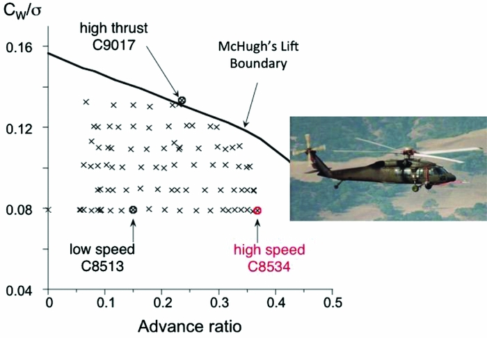
The first, the NASA/Army UH-60A Airloads Flight Test Program conducted at NASA Ames Research Center in 1993-1994(Reference Kufeld, Balough, Cross, Studebaker, Jennison and Bousman48), was a significant step forward. This seminal programme provided a detailed airloads and blade loads database for a broad flight envelope, depicted in Fig. 18, and became a resource of incalculable value to advance rotorcraft aeromechanics in subsequent years. The second key event, the Airloads Workshop, is described next.
NASA/Army UH-60A Airloads Flight Test Program, 1993–1994 and test envelope(Reference Kufeld, Balough, Cross, Studebaker, Jennison and Bousman48).

8.3 Airloads workshop
By its very nature, research rarely follows a logical, ordered path. It often proceeds in discontinuous steps, jumps, or leaps. Research initiatives may be unconventional, unpopular with management or organisations, or fail to gain support within the technical community. At times, politics and scarce resources impede progress.
During the CFD/CSD doldrums, the author proposed a collaborative effort, based on previous experience(Reference Ormiston49), to address the airloads prediction problem and exploit the UH-60A Airloads Flight Test database. In 1998, the National Rotorcraft Technology Center/Rotorcraft Industry Technology Association (NRTC/RITA), later Vertical Lift Consortium (VLC), supported R&D projects among industry partners where data were shared in a non-proprietary manner. The vision of the collaborative effort was to leverage synergy of top government, industry and university experts to advance rotorcraft aeromechanics prediction methodology. The approach, governed by consensus, was to trade ideas informally, to focus on specific datasets and to jointly compare analyses and assess the results.
Although specialists in the technical community overwhelmingly supported the initiative, it became a target for a few critics and naysayers and was nearly derailed. Even after two years of effort, it was not officially approved as an NRTC project. Nevertheless, as the old saying goes, “It's easier to ask forgiveness than it is to get permission.” Accordingly, the key experts in the technical community decided to meet regularly, and significant progress quickly followed. Committees are often clumsy and inefficient; sometimes, as in this case, committees far surpass the capabilities of the individual members.
The Airloads Workshop ultimately changed the course of aeromechanics research in the United States. The lesson is that unconventional approaches can lead to significant technology advancement. This should be uppermost in mind when considering innovative ways to revitalise R&D for advanced rotorcraft.
8.4 CFD/CSD loose-coupling breakthrough
The Airloads Workshop collaborators first reviewed the existing state of the art for airload predictions by focusing on a high-speed test point of the NASA/Army UH-60A Airloads Flight Test(Reference Tung and Ormiston50,Reference Datta, Nixon and Chopra51) . Each organisation used its best aeromechanics methods to predict the airloads and blade loads. As expected, none were able to accurately account for the measured normal force phase shift and blade-tip pitching moment highlighted by Bousman in Ref. 52. However, Jim Duh of Sikorsky applied the measured airloads to the DYMORE(Reference Tung and Ormiston50) finite-element multi-body dynamics code and was able to accurately predict the measured blade bending and torsion loads. This gave confidence that the airloads difficulties were not due to blade structural dynamics analysis.
The group quickly applied CFD methods to several subsets of the rotor airloads problem. After encouraging results, the DYMORE elastic blade deformations from the measured airloads were used as input for CFD airloads analysis. Initial results were disappointing due to discrepancies in the low-frequency airloads. However, at the Workshop meeting in February 2003, Datta and Sitaraman, as noted in Ref. 50, showed that, by removing the 1/rev airloads, the remaining vibratory normal force and pitching moments closely matched the measured airloads. This was the key demonstration that CFD could predict high-speed rotor airloads.
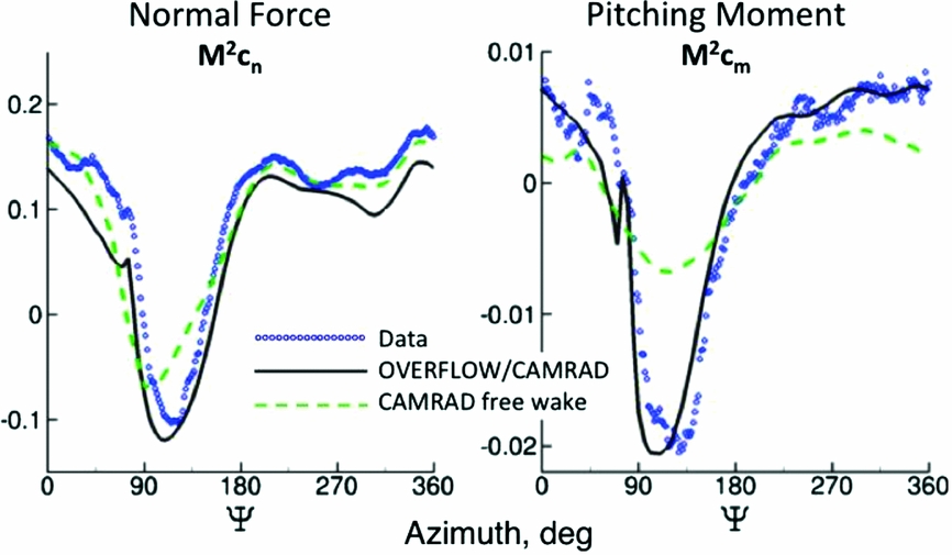
Thus, the problem became one of determining the correct 1/rev blade motion – in other words, solving the rotor trim problem. Relatively quickly, Potsdam et al(Reference Potsdam, Yeo and Johnson53) decided to revisit the original loose-coupling approach of 1986 and met with immediate success, as dramatically evident by the close agreement of CFD/CSD normal force and pitching moment airloads with measured data (Fig. 19). Ironically, the author discouraged this approach based on the frustrations and lack of success of many investigators during the doldrums between 1986 and 2003.
Airloads Workshop CFD/CSD loose coupling breakthrough, UH-60A high-speed airloads, r/D = 0.965, μ = 0.368(Reference Potsdam, Yeo and Johnson53).

This breakthrough of practical coupling of CFD and CSD codes opened the door to finally realising the benefits of CFD for the all-important aeroelastic problems of rotorcraft(Reference Bousman54,Reference Johnson55) .
In retrospect, the CFD/CSD coupling development, stretching over 15 years, succeeded largely as a result of a unique flight-test database and a collaboration of the top experts in the rotorcraft community. Similar efforts in Europe were hampered by less advanced databases and computational capabilities, although significant progress and contributions were made as early as 1994, for example, in Ref. 56.
Ironically, both the NASA/Army UH-60A Airloads Flight Test and the Airloads Workshop were very nearly derailed by narrow thinking. Without this tenuous confluence of efforts, it is interesting to speculate how long it would have taken for CFD/CSD coupling to emerge, and what forces might now be limiting our ability to achieve the next breakthroughs in aeromechanics and advanced rotorcraft.
Following the success of CFD/CSD loose coupling and airloads prediction for trimmed flight, attention turned to the challenging manoeuvre loads problem. It is critical for structural design of the blades, hubs and control systems because the high thrust manoeuvre loads include blade stall and are typically the highest encountered by the rotor. Conventional CA analyses have limited capability for such conditions, and CFD/CSD tight coupling is needed and requires data to be exchanged at every time step.
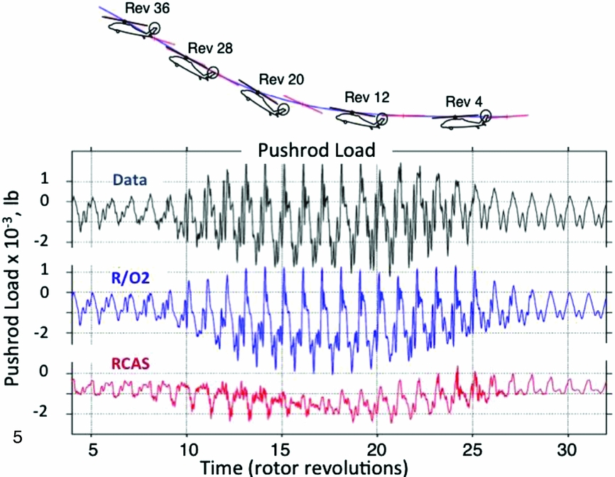
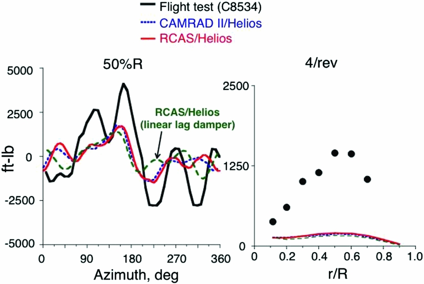
A manoeuvre solution was first demonstrated in the Airloads Workshop and presented in Ref. 57. The flight condition was the NASA/Army UH60A Airloads Flight Test ‘UTTAS pull-up’ a 2.1g abrupt pull-up from high-speed level flight. Extensive retreating blade stall and even ‘advancing blade stall’ due to compressibility were encountered with pushrod loads several times higher than in 1g level flight. The CFD/CSD tight-coupling results from RCAS and OVERFLOW-2 (R/O2) agreed closely with the flight-test measurements, unlike the RCAS CA analysis, as shown in Fig. 20. Tight-coupling CFD/CSD was also successfully applied to the aeroelastic stability problem in 2009 by Yeo et al(Reference Yeo, Potsdam and Ormiston58).
CFD/CSD tight-coupling manoeuvre loads prediction compared with CA prediction and measured UH-60A pushrod loads(Reference Bhagwat, Ormiston, Saberi and Xin57).

CFD/CSD methodology is the most revolutionary advancement in rotorcraft analysis in decades. It is a critical technology for the development of all future rotorcraft. However, there is much more that can be done, including rotor airloads and blade loads predictions beyond the UH-60A rotor system. Some of this is being carried out by the US Army under the CREATE-AV™(Reference Sankaran, Wissink, Datta, Sitaraman, Jayaraman, Potsdam, Kamkar, Katz, Mavriplis, Roget, Chen, Saberi, Johnson and Strawn59) and other programmes. Other opportunities from the Airloads Workshop experience have yet to be realised; some of these are addressed in the next section.
9.0 PART 3 – REVITALISING ROTORCRAFT RESEARCH
9.1 Compound research
A strong rationale for targeted compound research was identified in Part 1 based on the potential return on investment of this research. Accordingly, specific recommendations to initiate aggressive R&D to advance compound technology are being proposed.
The recommendations for compound R&D do not include full-scale flight research, but the future integration of technologies for such an aircraft deserves comment. Any initiative to achieve a truly successful compound demonstrator requires a ‘clean-sheet-of-paper’ approach. The 1960s compounds started with existing airframes and the aerodynamic efficiency gains were very limited. The Sikorsky X2 and the Airbus Helicopters X3 demonstrated significant advances, but the full potential of compound aerodynamic efficiency has not yet been established. The CarterCopter was designed for aerodynamic efficiency and does appear to have increased L/De over conventional rotorcraft(Reference Carter and Lewis13).
The proper and technically rational way to advance compound technology is to address critical component technologies in a step-by-step, building-block fashion. After creating that technology base, an optimised, fully integrated compound flight demonstrator could be designed, from the ground up. This would provide the best chance for success for the lowest RDT&E cost. Therefore, recommendations for aggressive compound R&D address all of the relevant technology issues. By demonstrating success in dealing with these key challenges, the stage is set for a truly successful and convincing compound flight demonstrator.
9.2 Cycle time factor
One more factor is relevant for advancing rotorcraft technology. This is the evolutionary progress arising from repetitive development in which new generations of aircraft are designed, developed, produced and then put into operation. This repetitive cycle creates opportunities to learn from experience, refine processes, test new design concepts and observe what works in the field and what doesn’t. New research is introduced when ready, design engineers’ skills are honed, and the users refine their requirements by operating new aircraft in the real world. This evolutionary process mimics Darwinian natural selection, which facilitates progress by naturally selecting successful designs.
Unfortunately, the decrease in new development programmes in recent years has impacted the efficiency of the design development process and inhibited the R&D in new technologies as well. Organisational experience has diminished, and the users and operators have had fewer opportunities to assess requirements by operating new aircraft with different characteristics and mission performance.
This leads to the question: Are there innovative R&D approaches that can mitigate the adverse impact of this increasing ‘cycle time’? The author believes the answer is yes, and these approaches are considered in the proposed recommendations.
9.3 Aeromechanics research
The background of rotorcraft development (Part 1) and aeromechanics research (Part 2) showed the importance of aeroelastic stability research and prediction methodology. Accordingly, recommendations are proposed to restore and reinvigorate research in rotorcraft dynamics and aeroelasticity, and to advance prediction methodology for effective design by supporting and strengthening comprehensive analysis and by continuing to advance CFD/CSD methodologies.
10.0 TEN RECOMMENDATIONS TO REVITALISE ROTORCRAFT AEROMECHANICS R&D
To support the three goals of this paper, 10 recommendations to revitalise research for advanced rotorcraft are listed here. They deal with diverse research opportunities in aeromechanics disciplines, design methodologies, research processes, acquisition of technical data, and components and concepts relevant to conventional and compound rotorcraft development. Those marked with an asterisk address the cycle-time factor discussed previously.
1. Low-drag hub design research*
2. Low-drag rotor
3. Large-scale research rotors
4. Hover performance research*
5. Dynamics and aeroelastic stability
6. Strengthen comprehensive analysis
7. Rotorcraft CFD initiatives
8. Vehicle control integration
9. Small-scale unmanned flight research*
10. Effectiveness of the R&D process
All of these recommendations support the goal of research to enable the compound; in addition, many of the recommendations support the goals to reinvigorate aeroelastic stability research and to advance prediction methodology.
11.0 LOW-DRAG HUB DESIGN RESEARCH
Initiate broad-based, low-drag hub research, design and development.
The primary limitation of the compound helicopter is poor aerodynamic efficiency. To achieve meaningful mission performance gains, for example, approaching the tiltrotor, requires aggressive technology development focused on drag reduction – fuselage drag, rotor drag and hub drag. All three are important, especially for high-speed rotorcraft, and all must be reduced. The full benefit of reducing one drag component is lost if the others are not also reduced. Because of the long-standing difficulty of reducing hub drag, this is the place to start.
Development of low-drag rotor hubs is an interdisciplinary problem of aerodynamics, dynamics, loads and control implementation. The following discussion addresses hub design and technical issues, suggests a candidate hub concept, and proposes an RDT&E approach for low-drag hub technology.
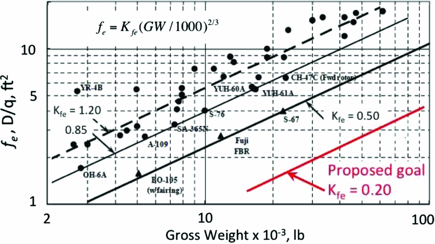
To start, consider the hub drag of current rotorcraft shown in Fig. 21, from Frank Harris's book, Ref. 7. The data is shown in terms of the equivalent flat plate drag area, fe, D/q (ft2) as a function of vehicle gross weight, GW, as defined earlier in Equation (1). The trend lines included in this logarithmic plot reflect a square-cube law relationship between hub drag and gross weight, and Kfe is a relative measure of hub drag. The large variation in the data suggests that design details significantly influence hub drag. Harris identifies two technology levels, typical and possible technology, with Kfe = 1.2 and 0.85, respectively. The latter bounds the lower range of current helicopter rotor hubs. A few faired hub data points show lower drag. Anticipating future research, the value of Kfe = 0.4 was used for several of the compound design studies discussed earlier and summarised in Fig. 9.
Harris's compilation of helicopter hub drag data(Reference Harris7) including proposed R&D goal for low-drag hubs.

It is proposed that a Kfe value of 0.2 be adopted as a target for practical low-drag rotor hubs. This is a challenging goal but one that is needed for compound rotorcraft to achieve desired levels of aerodynamic efficiency and mission performance.
11.1 Low-drag hub design
Because hubs tend to be un-streamlined ‘bluff bodies’, hub drag is primarily a function of net frontal area(Reference Keys and Rosenstein60). It is possible to add fairings, but because they are generally not slender and must provide openings for the rotor shaft and blade shanks, they are difficult to streamline. Fairings also tend to increase frontal area(Reference Young, Graham and Stroub61).
Numerous hub types have been used successfully, including teetering, articulated, gimbaled, hingeless, bearingless etc. Blade retention hinges, lead-lag dampers, torque tubes, pitch horns, pushrods and swashplates all contribute to frontal area. For hingeless rotors, dynamic characteristics such as fundamental flap and lead-lag frequencies influence blade structural loads, aeromechanical stability, weight and geometry. All of these influence the hub shape, size and frontal area. As a result, the aerodynamic design of low-drag hubs is interdisciplinary; researchers and designers specialising in aerodynamics, dynamics, structures and control must collaborate to develop innovative, new low-drag rotor hubs.
11.2 Hub design candidate
A novel hub design concept is offered to illustrate one approach to reduce hub drag. It is based on an important opportunity available to the compound in which, in cruise, the rotor shaft angle of attack and collective pitch are very nearly zero, unlike the conventional helicopter. This enables the potential for very low hub drag. In hover and at low speed, large collective and cyclic pitch are required, the hub components become misaligned and the hub drag is increased. However, this is not an issue because hub drag is only really important in high-speed cruise.
The proposed hub begins with an inherently low-drag configuration, the ‘door-hinge rotor’ that was used for the Lockheed Cheyenne stiff-inplane hingeless main rotor. The hingeless rotor is a leading candidate for compound helicopters for reasons of blade dynamics and aeroelastic stability at high advance ratio. Because a lead-lag damper is not required, drag is further reduced. Unfortunately for the Cheyenne, the gyro, pitch links and the pitch horns considerably increased the hub frontal area (see Fig. 22). However, a modern compound rotorcraft does not need an external gyro.
Lockheed AH-56A Cheyenne rotor hub showing pitch horns and pitch links contributing to high drag.

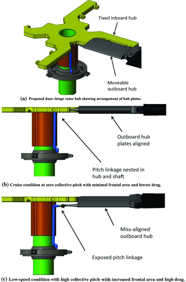
The virtue of the door-hinge rotor is that the hub frontal area is reduced to the minimum necessary for the structural members. The mechanical arrangement of the proposed hub comprises structural elements shaped roughly as flat plates – a fixed plate attached to the rotor shaft and a moveable plate attached to the blade – inboard and outboard of the pitch-change bearings, respectively, as shown in Fig. 23(a). The plates are hinged along a common edge like the familiar door hinge. So, for a compound in cruise flight, at near-zero collective pitch and shaft angle-of-attack, the two hub plates align with the free stream velocity and minimise drag – just when needed. For the proposed concept, the pushrods and pitch links would be nested against the rotor shaft and inboard hub plates to reduce frontal area to a minimum, as shown in Fig. 23(b). In hover and at low speeds at high collective pitch, where drag is not important, the hub plates would not be aligned, the pushrods and pitch links would no longer nest with the hub, and the hub drag would increase, as in Fig. 23(c). Note that the swashplate would be enclosed within the fuselage.
Low-drag hub design concept for compound helicopter.

The present concept does not use a separate hub fairing but simply minimises hub frontal area. It leverages the opportunity to confine the hub design challenge to one operating condition where low drag is achievable. In effect, the pitch horns, pitch links and outer hub plates of this hub concept are ‘retractable’, just like retractable landing gear. The pitch control components are exposed at low speeds and then retracted for efficient high-speed cruise.
11.3 Hub design research approach
A novel approach is proposed specifically for low-drag hub R&D that combines research, concept development, design studies, prototyping and testing to jumpstart long-neglected research and provide rapid technical progress for very modest cost. This approach includes the following elements.
1. Specify candidate mission requirements.
2. Identify several promising candidate rotors and hub configurations.
3. Perform preliminary design of rotor and hub.
4. Perform detail design sufficient for aeromechanics analysis to determine blade/hub loads.
5. Perform detail design to determine hub shape, size, stress and weight.
6. Determine hub drag using both empirical methods and high-fidelity CFD analysis.
7. Iterate the design to refine and optimise hub structure, weight and drag.
8. Construct low-cost, non-structural models for wind-tunnel testing at full-scale flight conditions to ensure full-scale Reynolds number measurements.
9. Validate and calibrate design tool accuracy, CFD in particular.
10. Develop numerous designs for analysis and testing to build experience and a hub design database.
There are many benefits from this approach. It is very cost-effective because drag test models would not be required to satisfy costly dynamic loads and structural design requirements. Data for many practical hub configurations would be obtained without lengthy and expensive development of new aircraft. Multiple design cycles would enable researchers and designers in relevant disciplines to accumulate experience and build skills. Multiple designs for various hub configurations and mission requirements would evolve and validate optimal low-drag hub technology.
12.0 LOW-DRAG ROTOR
Focus R&D to reduce high-speed rotor drag.
The second important category of drag reduction is the rotor itself. This refers to the drag of the rotor blades outboard of the rotor hub, typically termed the rotor profile drag or power; at high advance ratio the rotor profile power appears primarily in the form of drag rather than torque. Because a compound rotor does not supply significant lift in cruise, it simply adds drag; the goal is to reduce this drag to a minimum.
The high-speed rotor drag problem comes from the 2D Aerofoil profile drag and the blade radial drag. For a given rotor speed, drag increases with advance ratio, aerofoil angle of attack, reverse flow, solidity and blade twist. These design parameters also impact low-speed aerodynamic characteristics, thus design trade-offs must be made. Like the rotor hub, low-drag rotor design is an interdisciplinary problem because the effects of reverse flow and high advance ratio significantly impact rotor control response, dynamics and blade aeroelasticity.
The most effective way to reduce rotor drag is to slow the rotor's rotational speed. An illustration for slowed-rotor drag reduction given by Harris in Ref. 62 is adapted in Fig. 24. The incremental drag build-up as a function of rotor lift shows the drag of the airframe alone, the airframe and rotor hub, and then with rotor blade drag. The rotor speed ranges from a nominal value at advance ratio, μ = 0.5, decreasing to the stopped rotor at μ = infinity. At μ = infinity, the zero-lift drag is reduced to half of the total baseline (μ = 0.5) drag. The vehicle aerodynamic efficiency, L/De, is substantially increased, from 10 to 13.4.
Rotor drag build-up and the effect of reduced rotor speed(Reference Harris62).

There are other important opportunities to reduce rotor profile drag at high advance ratio. For a given blade radius and solidity, the blade geometry – planform shape, twist, tip shape and aerofoils – may be optimised for minimum drag. Low blade twist is important for high advance ratio because the inboard retreating blade operates in the reverse flow region and aerofoil drag is significantly increased, particularly for conventional aerofoils with sharp trailing edges. Because blade twist and aerofoil design affect hover performance as well, design trade-offs must balance requirements for these two regimes. Clearly, this is a significant opportunity to apply advanced CFD methods.
Aerofoil design is a particularly interesting area for reducing rotor drag at high advance ratio. Conventional rotor aerofoils are constrained by the need to compromise between retreating blade stall, advancing blade compressibility and low pitching moment. Aerofoil design offers limited opportunities for improving rotor performance because the available gains were largely realised long ago. The compound rotor, on the other hand, offers the opportunity for a fresh clean-sheet-of-paper approach to aerofoil design without the high-lift requirements and compressibility constraints of conventional rotors. The relevant goal for the high-speed compound is minimisation of reverse flow drag, thus aerofoils efficient for both forward flow and reverse flow must be developed. Of course, the hover efficiency requirements must also be included.
13.0 LARGE-SCALE RESEARCH ROTORS
Develop dedicated large-scale research rotors.
Develop and test two large-scale dedicated research rotors to acquire high-quality aeromechanics databases applicable to future advanced helicopters and compound rotorcraft.
The value and cost-effectiveness of small-scale research rotors is indispensable. However, some research needs can only be met with large-scale research rotors. Such was the case for the NASA/Army UH-60A Airloads Flight Test that provided the catalyst for significant breakthroughs in CFD/CSD prediction methodology.
At some point, the lack of accurate high-quality data impacts the accuracy and effectiveness of design methodology. This, in turn, limits the ability of the design methodology to produce rotorcraft of the highest achievable mission performance. We are close to that point for future advanced rotors. Although the UH-60A Airloads Flight Test yielded unprecedented experimental data, the UH-60A was a production rotor not designed for research testing. As a result, there were some uncertainties in measured data as well as rotor blade physical properties, and some prediction-versus-measurement differences could not be resolved. One of the principles of the AFDD aeroelastic stability R&D programme was to design and tailor models specifically to minimise inaccuracies in both the experimental data measurements and the model physical properties.
For these reasons, it is important that large-scale dedicated research rotors be developed and tested in a large-scale wind tunnel. The wind-tunnel environment offers the best means to control test conditions, ensure high-quality data and minimise R&D cost. Large-scale rotor testing ensures representative structural characteristics, Reynolds and Mach numbers, and a wide range of sophisticated rotor balance, blade instrumentation, and flowfield diagnostic measurements.
The first dedicated research rotor is needed to advance compound rotor technology. In the 1960s, NASA and the Army investigated high-advance-ratio rotor aeromechanics with three dedicated full-scale rotor test programmes carried out in the NASA Langley and Ames full-scale wind tunnels(Reference Sweet, Jenkins and Winston63-Reference Charles and Tanner65). These were the 15 ft, two-blade Jenkins rotor, the modified four-blade H-34 rotor and the modified two-blade Bell UH-1 rotor (Fig. 25). More testing of this kind is needed now. The principal objectives would be to obtain accurate, reliable experimental data to support advanced rotor design, and validate prediction codes for a blade configuration representative of future compound rotors and operating at advance ratios greater than two. This means low-twist blades and aerofoils tailored for large regions of reverse flow. Provision should be made for alternate blade tip and root sections to study the aerodynamics of these important regions.
Full-scale high-advance-ratio rotor tests in the NASA Ames 40 ft by 80 ft and the Langley 30 ft by 60 ft full-scale wind tunnels(Reference Sweet, Jenkins and Winston63-Reference Charles and Tanner65).

The second dedicated large-scale research rotor simply reflects the fact that the conventional helicopter will continue to evolve as it offers the most cost-effective performance for hover and low-speed missions. It is time to proceed beyond the limits of the UH-60A Airloads Flight Test and provide new, accurate, high-quality data for a modern rotor to enable the technology and tools to advance to the maximum extent possible within the inherent limits of the conventional helicopter.
14.0 HOVER PERFORMANCE
Create an accurate hover performance database for a variety of rotors.
The hallmark of low-disk-loading helicopter and tiltrotor VTOLs is hover efficiency. To advance the state of the art in this important area, a high-quality experimental database is needed to help refine hover performance predictions and to stimulate development of rotor configurations with improved figure of merit.
The need arises from the limited accuracy of current databases. Developers of advanced prediction methods must rely on experimental data, much of it acquired many decades ago, that does not reflect today's sophisticated experimental methods and measurement techniques. It is somewhat surprising that an accurate and consistent database for a variety of rotor types does not exist. Contrast this with widely available 2D aerofoil databases, most evident in Abbott and von Doenhoff's classic compilation of NACA aerofoil data(Reference Abbott and von Doenhoff66).
Figure 26 illustrates this problem, showing differences in small-scale UH-60A experimental model data obtained in two separate tests along with a typical analysis prediction. This data has been widely used to ‘validate’ predictions of rotor hover performance even though there is an uncertainty in figure of merit of about 0.05 between the two sets of data(Reference Bhagwat, Caradonna, Schmitz and Moulton67).
Significant differences in two different measurements of small-scale model UH-60A hover figure of merit lead to uncertainty in validating prediction methods(Reference Bhagwat, Caradonna, Schmitz and Moulton67).

The ability to predict performance with advanced methods, CFD in particular, is increasing, but the ability to validate these methods is limited when the error bounds of the data exceed the accuracy expected of the prediction codes. One count in figure of merit is now considered to be an increment worth considerable effort by designers. Experimental data and prediction methods should be at least this accurate. Lacking any other objective target, the present recommendation is to acquire data accurate to within a half count in figure of merit, 0.005.
Given the capabilities of modern experimental methods, instrumentation and data acquisition systems, it is time that this deficiency is addressed. It is suggested that R&D be initiated along the following lines to enable low-cost, innovative hover testing for a variety of rotors.
1. Eliminate facility effects by conducting ‘no-excuses’ outdoor testing.
2. Develop an automated robotic test stand to acquire large amounts of data during suitable quiescent conditions without requiring researchers to be present.
3. Use small-scale blades to reduce cost but of sufficient size (approximately 12-15 ft diameter) and tip speed for reasonable Reynolds number.
4. Limit experimental measurements to low-cost thrust and torque measurements – without blade pressure data or wake measurements.
5. Exploit novel ‘non-aerospace’ blade design and fabrication techniques to reduce cost and time by orders of magnitude.
6. Develop multiple blades to test parametric variations in blade twist, planform, tip shape and blade number.
The value of this approach is to quickly and cost-effectively acquire useful data to benefit near-term rotor design and tool development. Foregoing blade pressure instrumentation and flowfield measurements focuses testing on the essential data needed to validate rotor thrust and power predictions. Future testing with sophisticated rotors and instrumentation will provide detailed rotor flowfield and airloads data to fully assess, refine and validate prediction codes – in the longer term – and will be much more expensive and time consuming.
To stimulate design research to improve rotor hover performance capability, design competitions should be initiated for student groups. The American Helicopter Society (AHS), government, industry, or universities could sponsor such a competition. The Sikorsky Prize for the Human Powered Helicopter (HPH) and other AHS competitions have yielded impressive results. This approach offers an excellent educational opportunity for hands-on research, design and engineering. Rotors would be designed and tested for maximum hover figure of merit. By accumulating data from successive competitions, rotor design technology would evolve and the real-world state of the art in hover performance would be advanced.
15.0 DYNAMICS AND AEROELASTIC STABILITY
Reinvigorate rotorcraft dynamics and aeroelasticity research.
Despite the enormous advances in prediction methodology, historical experience reinforces the ever-present risk of unanticipated aeroelastic issues. This risk is elevated by the scarcity of rotorcraft development programmes because designers have fewer opportunities to apply design methods to new configurations. Moreover, the once-vigorous AFDD programme in small-scale experimental aeroelastic stability research is essentially non-existent today, and research for compound rotorcraft aeroelasticity has long been neglected.
Therefore, experimental research in rotorcraft aeroelastic stability should be restored. The objectives and approach of the past should be adopted and applied to the research needs and opportunities of future advanced compound rotorcraft. For example, operation at high advance ratio is more sensitive to dynamics and aeroelastic phenomena, including blade-flapping stability, blade pitch-flap flutter in reverse flow (centre of gravity at the three-quarter chord), and overall blade response, vibration, loads and rotor control.
As a suggestion for one research task, consider blade-flapping stability at high advance ratio. Analytical results for this problem, shown in Fig. 27, were obtained by Peters and Hohenemser in the first practical rotorcraft Floquet theory application in 1971(Reference Peters and Hohenemser68). These fundamental results are relevant to slowed-rotor compound design but they have never been experimentally validated (see Fig. 17). There is little reason to doubt their validity, but it would be quite valuable, and not at all difficult, to confirm them with a simple small-scale model rotor. This is just one suggestion among many worthwhile topics included in Fig. 17 for a programme to revitalise research in this important area.
Blade flap damping contours in forward flight based on linear Floquet analysis; Peters and Hohenemser(Reference Peters and Hohenemser68).

16.0 STRENGTHEN COMPREHENSIVE ANALYSIS
Prioritise research and maintain strong efforts to support and advance comprehensive analysis.
As noted earlier, comprehensive analysis is a mainstay of rotorcraft technology that provides unique and distinct capabilities and complements higher-fidelity CFD methods. CA also constitutes and provides the unifying interdisciplinary framework for rotorcraft analytical methods. It is essential that CA not be neglected in favour of CFD methods.
With respect to the Army-sponsored RCAS comprehensive analysis, several near-term functionality enhancements should be introduced. These include lifting surface modelling for higher-fidelity rotor blade aerodynamic analysis, extending Dynamic Inflow modelling to the flowfield surrounding the rotor disk for vehicle aerodynamic interactions, developing more computationally efficient Floquet analysis methods for large systems, and developing efficient parameter identification methods for post-processing CFD/CSD time-domain data.
Comprehensive analysis should also be introduced into the academic environment to provide unique approaches for teaching and research, and to better prepare students with ready-to-go knowledge and skills applicable to tools in use by industry.
17.0 ROTORCRAFT CFD INITIATIVES
Focus CFD development on validation and on overcoming deficiencies in comparison with existing and future experimental databases.
Computational Fluid Dynamics (CFD) research represents the cutting edge of efforts to crack the unsolved complexities of fluid physics phenomena that challenge rotorcraft advancement. Despite the revolutionary breakthroughs in CFD/CSD coupling that enabled CFD to treat rotorcraft aeroelastic problems, the full challenges of rotorcraft still require more from CFD technology. In addition, there will always be a continuing need to improve the efficiency and ease of use of CFD methods for all aerospace applications.
Some of the remaining challenges are evident in rotor airloads and blade loads predictions for the NASA/Army UH-60A Airloads Flight Test. For example, while CFD/CSD has significantly improved airloads prediction, blade structural loads prediction has not been equally successful. An example is shown in Fig. 28(Reference Yeo and Potsdam69) comparing predicted blade chord-bending moments with high-speed flight-test data where the 4/rev blade loads are significantly under-predicted. It is becoming clear that a key contributor to the problem is neglecting dynamic coupling between the rotor and the drive train.
Example of difficulty predicting UH-60A blade chordwise bending moments in high-speed forward flight with CFD/CSD methods(Reference Yeo and Potsdam69).

Another challenge is prediction of a stall spike that occurs on the advancing blade at high rotor lift during the UTTAS pull-up manoeuvre. Very large, normal force and pitching moment peaks occur at low angles of attack and high Mach number. Unlike retreating blade stall at high angle of attack and low Mach number, advancing blade stall has proven considerably more difficult to predict.
The availability of rotorcraft CFD/CSD capabilities opens up numerous opportunities for attacking long-standing rotorcraft problems – and because of their importance, these problems need to be pursued. However, simply ‘running’ some of these problems entails significant setup effort for the physical configuration, structural properties and CFD grids. Acquiring suitable experimental data is often difficult.
The rotorcraft empennage problem is an example of such an opportunity. Various structural load, vibration and flight control issues arise from rotor, hub and fuselage unsteady aerodynamic excitations that combine with empennage structural dynamics. This is a complex, interdisciplinary, 3D aeroelastic problem. Crawford highlighted its importance in his 1989 Nikolsky Lecture on UTTAS and AAH development issues(Reference Crawford44). The empennage problem is amenable to current CFD/CSD methods and addressing it is long overdue.
There are many needs and opportunities for rotorcraft CFD research. Validations and assessments such as the Airloads Workshop and the UH-60A are essential. Demonstration applications such as the empennage problem need to be pursued. And fundamental CFD research is needed to solve basic problems such as smooth-body boundary layer transition and separation, static stall and turbulence, particularly for rotorcraft applications. Well-designed experiments are needed to produce reliable, high-quality data for separated flows, stall, dynamic stall and blade vortex interactions.
18.0 VEHICLE CONTROL INTEGRATION
Develop integrated control concepts providing functionality to optimise compound rotorcraft performance and control.
The mission potential of advanced compounds requires integrated control of propulsion, trim and flight controls while ensuring acceptable vibration, loads and aeroelastic stability. Controller designs should be developed to optimise vehicle performance at all points in the flight envelope, and these controllers should be validated with small-scale wind tunnel and unmanned flight testing.
Modern flight control technology represents an ongoing revolution in mission effectiveness, operating cost and safety across the entire aviation spectrum. The impact comes from the aggregate effect of computers, sensors, hardware components, materials etc., and integration with all technical disciplines of the flight vehicle.
This revolution is particularly important for advanced compound rotorcraft. To achieve the full mission performance, control integration must embrace the entire vehicle – not only to control vehicle flight dynamics but also to ‘manage’ vehicle loads, performance and aeroelastic stability. The terms active control, active loads control, active flutter suppression etc., have all been used in the past to describe the functions that are now expected of integrated control for an advanced compound rotorcraft.
For maximum vehicle performance, the rotor must maintain optimum angle of attack and collective pitch to minimise rotor drag at high advance ratio. At these conditions, the rotor blade loads may be very sensitive to transients, gusts and manoeuvres. Minimising rotor weight will further challenge structural loads and aeroelastic instability. At the same time, the flight control system must manage rotor and vehicle trim and pilot control response to ensure excellent flying qualities. Vehicle vibration resulting from rotor, wing and fuselage aerodynamic interactions imposes further demands on the flight-control system.
While these are demanding requirements, they are quite attainable with the current flight control state of the art. Targeted studies are needed to establish appropriate requirements and then carry out research to best meet them. These tasks are inherently interdisciplinary and must be done in concert with aeromechanics and structures specialists. Traditional flight-control research conducted in simulators and flight tests is important, but the scope of the effort will likely expand to include small-scale wind-tunnel testing as well as small-scale unmanned-vehicle flight testing.
19.0 SMALL-SCALE UNMANNED FLIGHT RESEARCH
Explore small-scale unmanned flight vehicles for advanced rotorcraft aeromechanics and integrated control research.
In the early years of rotorcraft development, small-scale free-flight models played a prominent role in solving fundamental problems that stood in the way of practical autogyros and helicopters(Reference Ormiston70). For example, Juan de la Cierva conceived the articulated rotor-flapping hinge for his autogyro through experiments with free-flight models. Art Young invented the Bell gyro bar stabiliser using sophisticated, remotely controlled, electric-powered tethered helicopter models. And the Lockheed gyro-controlled rigid rotor that led to the AH-56A Cheyenne was developed with small-scale, radio-controlled, internal combustion-engine-powered helicopter models(Reference Prouty and Yackle10).
Today, unmanned aerial vehicle technologies are rapidly emerging in diverse sectors of the aviation community and opening important new opportunities for rotorcraft R&D. Unmanned vehicles have long been used for concept demonstrators, prototype development and flight research. Significantly expanded technical capabilities now available for smaller low-cost vehicles have created practical R&D opportunities not previously available.
The key enablers are low-cost electric propulsion systems, lithium batteries, miniaturised flight control systems, micro-electro-mechanical systems (MEMS) sensors, and high-capacity telemetry and data acquisition. The ubiquitous multi-copters and drones now available to consumers, hobbyists and small companies are creating broad awareness of the revolutionary potential of autonomous VTOL aircraft and stimulated an explosion of development, the extent and ultimate impact of which cannot be imagined. This capability also holds enormous potential to advance rotorcraft technology and should be exploited by researchers.
Just to illustrate how widespread this new technology has become – and how far the model airplane enthusiasts’ hobby has progressed – two illustrations are presented in Fig. 29. The first shows the author with a classic rubber band–powered balsa and tissue model in 1944, and the second shows inventor Ran D St Clair in 2015 with a V/STOL concept demonstrator, the Winged Utility Vehicle (WUV). This 4lb aircraft uses 18 electric motors for separate lift and propulsion in hover and cruise, and incorporates a sophisticated flight control and stabiliser system optimised for the full hover, transition and cruise envelope. The model includes data acquisition and telemetry capability, and is based entirely on inexpensive, commercial off-the-shelf (COTS) equipment.
Evolution of model airplane technology over 70 years provides new opportunities for free-flight concept demonstration and aeromechanics research.

In view of the significant and cost-effective capability of this new technology, research organisations should explore the potential capabilities for flight research as well as specific advanced rotorcraft concepts. Rather than replace analytical, laboratory, wind tunnel and full-scale flight test, the new capability complements and substantially augments traditional methodologies.
Advanced compound rotorcraft research in aeromechanics and flight control should be initiated with vehicles targeted as small as 100lb gross weight. The objectives would be to explore vehicle trim, steady-state rotor loads, manoeuvre loads and flight control integration. When necessary, small-scale wind-tunnel testing would evaluate performance and aerodynamic efficiency.
20.0 EFFECTIVENESS OF THE R&D PROCESS
Make research count. . . do the right thing and do it right.
It is important to do the right research. Said another way, to find the right answer, it is first necessary to ask the right question. The role and goal of research is to provide the basis to develop rotorcraft with improved performance and mission effectiveness, so the right research is what leads to practical mission payoff.
It is important to do research right. Effectiveness of R&D depends on many subtle, and not-so-subtle, influences. Research is an art, a creative process, and it is difficult to codify. It is also infinitely subjective even if the results of good research are easy to recognise.
Many specific prescriptions for research methods were presented in the discussion of aeromechanics research in Part 2. These are not repeated here but should be incorporated in the 10 R&D recommendations.
In an interdisciplinary field such as rotorcraft, basic research, applied research and advanced technology development (Department of Defense 6.1, 6.2, 6.3 R&D categories) should encompass a ‘full spectrum’ of technical activities: discovery, invention, prediction methods and data. Briefly described, discovery is acquiring or developing fundamental understanding, for example, fluid flow or dynamics phenomena; invention means conceiving or designing a device, concept, or rotorcraft; prediction methods include equations, algorithms, or solution methods for math models of fluid or physical systems; and data refers to databases from experiments or engineering data for design or validating prediction methods. A research programme needs the synergy of this full spectrum to be creative and successful. For example, focusing on prediction methods alone will not lead to conceiving a novel new rotorcraft concept.
Research should be guided by a rational plan to maintain focus on the goal, maximise effectiveness and enable progress to be assessed. However, there is a natural tension between research and planning. Ultimately, research entails exploring the unknown and so there are limits to planning. However, research unfettered without any plan runs the risk of losing sight of the goal. Researchers without discipline encourage critics who equate research with ‘playing in the sandbox’, which is not helpful for research in general.
Management has important roles, though these are admittedly difficult to define for research. The first is to support the researcher, then to define the mission, promote efficiency and assess the execution. It does not include micro-managing the research. Shortsighted management can stifle R&D effectiveness. Overly rigid adherence to schedules and milestones is counterproductive. Exploring the unknown is not schedule driven; rather, results drive the schedule. As noted earlier, the AFDD aeroelastic stability programme invariably performed each experiment twice, first to learn how to do it and then to do it right.
CONCLUDING REMARKS
Part 1 showed that neglect of compound helicopter R&D for more than three decades of the Compound Gap was largely the result of a quirk of history involving the dramatic reversal in fortunes of the compound and the tiltrotor in a very short period of time. Once again, aeroelastic stability technology was shown to play a critical role both in enabling advanced concepts to realise success and in posing a critical risk to ongoing development programmes.
The performance potential of the compound suggests that it should be a viable candidate to fill the mission gap between the (simple) low-speed helicopter and the (more complex) high-speed tiltrotor. The lower complexity of the compound compared to the tiltrotor should be considered in making selection decisions. It is time to exploit the compound opportunity and undertake focused R&D needed to unleash its full potential. This was the first goal of this paper.
Aeroelastic stability technology and prediction methodology are both essential to develop advanced rotorcraft. Part 2 reviewed research in both of these technologies to suggest new opportunities and to identify ways to plan and execute such research more effectively.
There has been a decline in fundamental research in aeroelastic stability. It is essential to restore and reinvigorate rotorcraft aeroelasticity research to reduce risk and ensure success of future advanced rotorcraft. This was the second goal of this paper.
It is essential to strengthen rotorcraft aeromechanics prediction methodology both for comprehensive analysis and for computational fluid dynamics technology. This was the third goal of this paper.
Part 3 provided ten detailed recommendations directed toward all 3 of these goals. These recommendations are believed to be essential to revitalise the future of advanced rotorcraft and to realise the potential of the compound.
DEDICATION
This Nikolsky Lecture is dedicated to the memory of Paul F. Yaggy, the first Technical Director of the U.S. Army Aeronautical Research Laboratory (AARL) at NASA Ames Research Center (Fig. 30). Paul's philosophy, contributions and legacy had much to do with the impact of Army and NASA researchers on the rotorcraft technical community as we know it today. In recognition of his contributions, Paul received the American Helicopter Society International's highest honour, the Alexander Klemin Award, in 1973. Together with the influence of the Army/NASA environment that he created, Paul's mentorship and influence helped immeasurably to shape my career and technical activity.
Paul F Yaggy, Technical Director, U.S. Army Aeronautical Research Laboratory.

ACKNOWLEDGEMENTS
The author is indebted to the following individuals and offers special thanks for encouragement, support, and material contributions: Mahendra Bhagwat, Frank Harris, Tom Maier, Mark Potsdam, Hossein Saberi, Bill Warmbrodt, and Hyeonsoo Yeo. Particular thanks are given to the incomparable AFDD Advanced Design Office team members: Wayne Johnson, Alex Moodie, Mike Scully, Chris Silva, Jeff Sinsay, and especially to Robbie Vocke and Gerardo Nunez for figure preparation. Finally, the author is grateful for support, inspiration, mentoring, and collaboration from and with Bill Bousman, Dewey Hodges, Jim McCroskey, Dave Peters, and Mike Rutkowski, and so many others in the rotorcraft community without whom he would not have been able to present the Nikolsky Lecture.