


Impact Statement
This paper addresses the urgent need for scalable inspection of aging infrastructure, as global maintenance demands outpace manual capabilities. The accelerating effects of climate change, including intensified weather extremes and groundwater shifts, are exacerbating deterioration rates in these critical structures, increasing risks of catastrophic failures that threaten public safety and economic stability. We present an autonomous robotic system integrating multi-sensor fusion and artificial intelligence-based damage detection to dynamically optimize inspection viewpoints. In real-world and controlled tests, adaptive pose adjustment increased detection confidence by an average of 18%, reduced the failure rate from 20% to 6.66%, and lowered the average measurement error from 23.31% to 10.09% (and to 3.05% when excluding missed detections). By automating high-risk inspections and generating actionable defect datasets, the system enables prioritization of critical repairs, reducing reliance on scarce expertise. This approach directly supports sustainable infrastructure management, offering a scalable solution to mitigate safety hazards caused by deteriorating assets.
1. Introduction
Civil infrastructures, geotechnical structures, transport, and utility networks play a crucial role in supporting modern urban and industrial systems (Koch et al., Reference Koch, Georgieva, Kasireddy, Akinci and Fieguth2015; Gamra et al., Reference Gamra, Ninić and Ghiassi2024; Babanagar et al., Reference Babanagar, Sheil, Ninić, Zhang and Hardy2025). However, this infrastructure is often subject to deterioration due to aging, environmental factors, and increased operational demands. Understanding the developed condition of urban infrastructure is critical, as failure to do so can lead to severe consequences such as service disruptions, structural failures, and threats to public safety. As cities continue to grow and evolve, ensuring the resilience and sustainability of urban infrastructure becomes increasingly important to mitigate these risks and maintain the quality of life for residents (Meerow et al., Reference Meerow, Newell and Stults2016; Huang et al., Reference Huang, Ninić and Zhang2021; Chen et al., Reference Chen, Lu and Lou2023; Gamra et al., Reference Gamra, Ninić and Ghiassi2024; Ninić et al., Reference Ninić, Gamra and Ghiassi2024). Effective damage detection and risk assessment are therefore vital to maintain the functionality and safety of these critical assets (Huang et al., Reference Huang, Ninić and Zhang2021).
Traditional methods for inspecting and assessing the condition of civil infrastructure heavily rely on manual inspections or semi-automated technologies for data collection, processing, and reporting. These methods are often time-consuming, labor-intensive, and limited in their ability to provide comprehensive, systematic, and real-time insights (Attard et al., Reference Attard, Debono, Valentino and Di Castro2018; Huang et al., Reference Huang, Ninić and Zhang2021). Additionally, accessing confined spaces in urban environments, typical for geotechnical structures and ground infrastructure, presents significant challenges, including limited entry points, hazardous conditions, and the need to minimize disruption to ongoing operations (Kopiika et al., Reference Kopiika, Karavias, Krassakis, Ye, Ninic, Shakhovska, Argyroudis and Mitoulis2025; Wang et al., Reference Wang, Xie, Fu, Zhang, Chen, Zhu and Zhang2024). As a result, there is a growing demand for advanced technologies that can overcome these limitations while enhancing the precision and efficiency of inspection and assessment processes (Ye et al., Reference Ye, Lovell, Faramarzi and Ninić2024). In recent years, artificial intelligence (AI), with its main technologies machine learning (ML), computer vision (CV), and robotics, has emerged as a transformative tool in the field of infrastructure monitoring. ML-powered algorithms coupled with robotic platforms offer the potential to revolutionize the way underground infrastructure damage detection and risk assessment are conducted (Protopapadakis et al., Reference Protopapadakis, Stentoumis, Doulamis, Doulamis, Loupos, Makantasis, Kopsiaftis and Amditis2016). By leveraging advanced sensors, machine learning, and autonomous navigation, these systems can rapidly collect, analyze, and interpret data from complex urban environments.
1.1. Literature review, gaps, and innovation
Some related studies and applications have already been implemented in civil infrastructure management and geotechnical structures monitoring. La et al. (Reference La, Gucunski, Dana and Kee2017) propose a robot platform by integrating multiple non-destructive evaluation (NDE) sensors and navigation control algorithms, enabling it to move autonomously and accurately across the bridge deck to collect visual images and perform NDE measurements. Chow et al. (Reference Chow, Liu, Tan, Su, Wu, Li and Wang2021) recently proposed an automated framework for concrete structure defect detection. The framework integrates data collection using 360° cameras and light detection and ranging (LiDAR). It then applies deep learning-based defect detection and uses simultaneous localization and mapping (SLAM) for site reconstruction. Finally, the results are incorporated into a building information model (BIM) for better facility management. Shim et al. (Reference Shim, Lee, Cho, Kim and Kang2023) created a remote robotic system that utilizes stereo vision to inspect damage on concrete surfaces. Wang et al. (Reference Wang, Xie, Fu, Zhang, Chen, Zhu and Zhang2024) deployed a small robotic platform for inspecting narrow-section hydraulic tunnels, and in this work, they proposed a system equipped with multiple synchronized shutter array cameras mounted around the mobile robot, which autonomously capture panoramic images of the tunnel interior. An improved object detection algorithm (You Only Look Once) YOLOv5, is then used to perform damage detection on the collected imagery. Lin et al. (Reference Lin, Chen, Chang and Shen2019) applied an ensemble learning method for crack detection in retaining walls by using a dynamic imaging system on an unmanned vehicle, integrating sensors and a camera to capture images, which are then analyzed with machine learning algorithms for crack location and risk assessment.
A series of studies (Ai and Yuan, Reference Ai and Yuan2019; Liu et al., Reference Liu, Zhong, Zhao and Song2023; Y Wang et al., Reference Wang, Liao, Dong, Xu, Zhu, Shi and Yu2024; Xu et al., Reference Xu, Wang, Dong, Zhu, Shi and Yu2023) have used robots that travel along subway tracks to perform panoramic imaging. These robots are often paired with odometers or inertial navigation systems to provide precise localization, enabling the collection of image data within subway tunnels. Additionally, large-scale inspection robots have been developed for highway tunnels, such as the ROBO-SPECT European FP7 project (Montero et al., Reference Montero, Menendez, Victores and Balaguer2017). This project proposed a system comprising a mobile vehicle, an extendable crane, a high-precision robotic arm, a computer vision system, and ultrasonic sensors. Through human–robot collaboration, the system facilitates both inspection and repair tasks. The applications of pipeline robots are extensive, primarily including pipeline inspection and maintenance (Jang et al., Reference Jang, Kim, Lee, Kim, Kim, Lee and Choi2022; Tang et al., Reference Tang, Du, Jiang, Shao, Dong, Liu and Zhao2022). Small robots designed to match the pipe diameter, deployed inside pipelines, where they navigate using sensors and cameras to detect cracks, corrosion, blockages, and other issues, ensuring safe operation. They can also perform cleaning, repairs, and data collection based on remote control in narrow or hazardous areas, improving efficiency and reducing the requirements for manual labor.
Overall, most current robotic platform-based inspection methods follow a comprehensive detection approach. This means they systematically collect complete data and capture images of the entire inspection area, such as an entire tunnel or retaining wall, before proceeding with damage identification. These methods rely on predefined navigation strategies to ensure thorough coverage of structural surface features. While thorough, this approach ignores the interaction between the robot and its environment. By employing effective interaction strategies, robots can dynamically adjust sensor parameters such as angles of sensors, fields of view, and distances between sensors and structural surfaces during inspection in an adaptive complex environment. This adaptability allows for more efficient and precise information collection, resulting in reliable detection while reducing data acquisition burdens. It also supports the design of universal robots that can adapt to various environments. Following this strategy, rather than full-scale data collection, the robot can perform a rapid initial inspection followed by targeted, precise data acquisition, minimizing the volume of information to process and transmit for comprehensive inspection while enhancing flexibility across different inspection scenarios.
1.2. Aim and objectives
Inspection robots with environmental awareness and autonomous response strategies offer great potential for future advancements, improving inspection accuracy and reliability (Floreano et al., Reference Floreano, Mondada, Perez-Uribe and Roggen2004; Jin and Zhang, Reference Jin and Zhang2020). The concept of “embodied intelligence,” which enables robots to interact with their environment in real-time using perception and algorithms, allows them to perform tasks in complex real-world conditions (Gupta et al., Reference Gupta, Savarese, Ganguli and Fei-Fei2021). This paper introduces embodied intelligence into the damage inspection robotic platform, enhancing its ability to adapt to environmental changes and specific damage types. Through dynamic sensory feedback, the system refines its actions based on real-time environmental conditions and damage characteristics. This human-like interaction allows for more precise and context-aware damage detection, distinguishing the proposed system from traditional methods.
The specific objectives in this paper are:
-
• Employing a small multi-sensor robotic platform and developing inspection workflows with environmental perception strategies.
-
• Incorporating real-time deep learning models as the foundation for damage detection, and refining robot actions and responses based on real-time environmental conditions and the characteristics of detected damage.
-
• Operating autonomously in challenging and unknown environments, the robot accurately maps detected damage onto a self-generated exploration map.
By addressing these objectives, the proposed platform has the potential to significantly enhance the efficiency, safety, and reliability of civil infrastructure monitoring. The novelty of our approach in achieving these objectives lies in: (1) the integration of adaptive pose adjustment after crack detection, which optimizes detection precision based on crack size and confidence level; (2) the fully autonomous operation of the system, enabling real-time crack detection without human intervention; and (3) the automated recording and labelling of cracks, which facilitates continuous improvement of machine learning models with higher quality data for more reliable structural health monitoring.
The remainder of the paper is organized as follows: Section 2 presents our methodology, providing a comprehensive explanation of the robot platform’s architecture, environmental perception methods and strategies, and the inspection workflow, including the detection and the damage-locating and projection process. Section 3 describes the implementation details, testing, and performance evaluation based on two case studies. Section 4 concludes the paper, discussing its limitations and suggesting directions for future work.
2. Methodology
2.1. Overview
In this section, we present our framework that integrates embodied intelligence into an existing mobile robotic platform (detailed in Section 2.2) for surface damage detection on geotechnical strictures. The entire framework is illustrated in Figure 1 and consists of the following parts: hardware components, software components, and the inspection process.
Flowchart illustrating the autonomous inspection framework for surface damage detection. The system integrates hardware components, including LiDAR, RGB-D cameras, and positioning sensors, with ROS nodes that process sensor data for mapping, navigation, and crack detection. Additionally, an Rviz (ROS visualization) node provides real-time visualization of mapping and navigation data. The main node coordinates robot control, utilizing DC motors for movement and a servo motor for camera adjustments. The YOLO node identifies cracks, while the mapping node updates the environment in real-time, ensuring precise localization and obstacle avoidance.

The hardware components of our framework are critical to enabling the robotic platform to perceive and interact with its environment effectively. LiDAR provides precise distance measurements and environmental mapping, while RGB and depth cameras capture visual and spatial data, respectively. Additionally, positioning and localization sensors, such as an inertial measurement unit (IMU) and odometer, are integrated into the robot to deliver precise positioning, localization, and orientation information. These sensors collectively deliver the necessary input for the robot to understand its surroundings. The data from these sensors are processed in real-time to generate actionable insights (see Section 2.3.2), which are then used to control the robot’s movement and camera orientation. Specifically, the robot’s motion is driven by direct current (DC) encoder motors, which are electric motors equipped with encoders to provide precise control over speed and position. Additionally, a servo motor, which is a rotary actuator capable of precise angular positioning, is used to adjust the camera angle for optimal image capture. By integrating sensor data with motor control, the system ensures accurate navigation and dynamic adjustment of the camera and its pose to enhance surface damage detection.
The robotic operating system (ROS) (Quigley et al., Reference Quigley, Conley, Gerkey, Faust, Foote, Leibs, Wheeler and Ng2009) is an open-source, flexible framework for developing and managing robot software, providing tools, libraries, and conventions to simplify the creation of complex robotic systems. It plays a central role in processing and using sensor data to enable the robot to “understand” its environment and its own state. In ROS, a node is a fundamental computational unit that performs specific tasks, such as processing sensor data, controlling actuators, or managing communication between components. Sensor-specific ROS nodes (Section 2.3.2) are responsible for converting raw input data into meaningful information. Once the sensor data is transformed into usable information, other ROS nodes leverage this data to enable advanced functionalities. As can be seen Figure 1, the mapping node constructs a detailed map of the environment using LiDAR, while the YOLO node processes an RGB image stream to detect surface damage using a YOLOv5-based model. The main node (inspection) serves as the central orchestrator of the system (Section 2.3.1), seamlessly connecting and coordinating all other nodes to ensure harmonious operation. It manages communication between nodes, synchronizes data flow, and issues commands to guide the robot’s navigation, damage detection, and data collection processes. Together, these nodes form a cohesive system that enables the robot to perceive, navigate, and interact with its environment autonomously.
As can be seen in Figure 1 the inspection process is orchestrated by the main node. The inspection begins by scanning the environment. If no cracks are initially detected, the robot navigates while sweeping its camera to ensure comprehensive coverage. Once a crack is identified, the robot dynamically adjusts its position and camera angle to optimize detection confidence. This involves iterative refinement of alignment (see Section 2.3) and proximity until the highest confidence score, a key metric reflecting the system’s certainty in the detected damage, is achieved. The system then records the detected crack’s image, confidence score, location, and bounding box. This seamless integration of perception, navigation, and decision-making enables the robot to autonomously inspect geotechnical structures with high precision and efficiency.
We elaborate on each component in detail in the following sections.
2.2. Robot platform architecture
The JetAuto Advanced Kit (JetAuto) is a robotics platform designed for research, development, and education of autonomous systems. The core of the system is the Jetson Nano mainboard (NVIDIA, 2024), a compact module that serves as the primary processing unit. It is responsible for processing sensor data, managing communication between system components, and executing control commands. The robot’s movements are controlled by an STM32F407 microcontroller, which ensures efficient motor control and real-time responsiveness. Together, these components provide the hardware foundation for the robot’s operation.
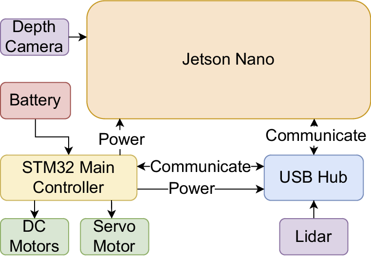
As shown in Figure 2, the robot is equipped with a range of high-performance hardware components. With its depth camera and a G4 LiDAR, it gives the robot perception capabilities for mapping, obstacle detection, and navigation. The four DC motors of the Mecanum wheels allow for omnidirectional movement, making it maneuverable in tight areas. Furthermore, a pan-tilt servo is employed to operate the camera, allowing dynamic modifications to its field of view and orientation, an essential feature for activities involving in-depth visual scanning.
Physical components of the robot platform, including sensors (Camera, Lidar), motion mechanisms (Mecanum wheels), power supply (Battery), control modules (STM32 microcontroller), and peripheral interfaces (USB Hub).

2.2.1. Jetson nano main controller
As shown in Figure 3, the Jetson Nano serves as the primary processing unit and ROS controller, handling high-level processing and system communication. It interfaces with sensors, actuators, and peripherals, processing data for real-time decision-making. For instance, when the LiDAR detects an obstruction, the Jetson Nano processes the input and sends movement commands to the STM32F407 microcontroller for obstacle avoidance. With its GPU-accelerated computing capabilities and support for deep learning frameworks, the Jetson Nano enables real-time perception and control while operating within a low-power envelope, making it suitable for autonomous robotic applications in resource-constrained environments.
Hardware integration of the robot platform, detailing physical connections and data communication pathways between components such as sensors, actuators, controllers, and power systems to illustrate their collaborative functionality.

The Jetson Nano’s capacity to process multiple neural networks simultaneously makes it possible to implement sophisticated deep learning tasks such as scene comprehension, object recognition, and semantic segmentation, necessary for effective damage detection. Since these abilities are essential for autonomous navigation and task completion, the Jetson Nano plays a key role in the robot’s capacity to engage with and adjust to its complex surroundings, typical for civil infrastructure embedded within the existing natural environment. Its assistance with GPU acceleration also improves the performance of the AI model for swift decision-making and stable system operation. Its assistance with GPU acceleration allows for real-time inference of AI models, ensuring that the robot can make low-latency decisions when detecting obstacles, identifying damage, or adjusting its navigation path in challenging environments.
2.2.2. STM32 robot controller
The robot controller’s central component, the STM32F407VET6 microcontroller, runs at a clock speed of 168 MHz and includes onboard flash memory and SRAM for real-time data processing. It manages low-level motion control and sensor integration, ensuring precise movement and stable navigation. It operates multiple DC encoder motors for chassis movement and a servo motor that adjusts the camera’s position, enabling dynamic viewpoint adjustments. Additionally, it processes data from the integrated IMU, which includes an accelerometer, providing essential feedback for motion stabilization and localization. This integration allows the STM32 to execute movement commands received from the Jetson Nano while also processing sensor feedback, ensuring accurate control and real-time adjustments in challenging conditions.
2.2.3. Depth camera
The Astra Pro Plus depth camera on the robot captures both depth and RGB data using 3D structured light technology. It consists of four main components: a depth processing unit, an IR projector, an infrared (IR) camera, and an RGB module. The IR projector emits structured light patterns onto a target scene, which the IR camera captures as infrared images. The depth processing unit then determines depth values by analyzing these images against a pre-calibrated reference pattern using structured light triangulation. The RGB module captures color images that complement the depth data.
The combined depth and RGB information is crucial for crack detection and localization. When the robot identifies a crack, it measures the distance to the object and logs the crack’s location. The location data are especially helpful in preventing duplicate recordings of the same crack, ensuring efficient and precise documentation of structural damage.
2.2.4. Light detection and ranging (LiDAR)
LiDAR is a sensor technology that measures distances with extreme precision using laser pulses. The time it takes for a sequence of laser beams to return after hitting an item is determined by the sensor. LiDAR uses these time-of-flight data to generate a point cloud, which is a very accurate depiction of the environment that provides precise distance data.
Features such as SLAM mapping, obstacle avoidance, and autonomous navigation are made possible by LiDAR sensor. The robot’s strong spatial awareness, which is essential real-time navigation tasks, is provided by the LiDAR system, which continuously scans its surroundings and locates anything. By continuously scanning its surroundings and updating its position, the LiDAR system supports autonomous real-time path planning, precise localization, and adaptive obstacle avoidance (Gatesichapakorn et al., Reference Gatesichapakorn, Takamatsu and Ruchanurucks2019; Sun et al., Reference Sun, Zhao, Hu, Gao and Yu2023).
Before any movement, the robot first analyses the LiDAR data to assess its surroundings and make navigation decisions accordingly. Suppose that the LiDAR detects an obstruction, such as overgrown vegetation encroaching onto a pavement near a retaining wall or plant roots pushing through the tunnel floor. In that case, the robot can stop and adjust its movement to navigate around the blockage safely. LiDAR helps the robot distinguish between static and dynamic objects, ensuring safe movement around construction barriers or dense foliage (Bartlett et al., Reference Bartlett, Santos, Moreno, Dalai, Fahy, Dow, Gonzalez, Trslic, Riordan and Omerdic2024). These capabilities are crucial for infrastructure maintenance, where the robot must accurately perceive environmental changes and precisely localize its position while manoeuvring through confined spaces.
2.3. Inspection workflow
In this paper, we propose an inspection of civil structures workflow to facilitate efficient communication between sensory and computational modules by implementing a node-based architecture within ROS. This architecture ensures effective execution in tasks such as autonomous navigation, mapping, damage detection, and pose adjustment.
Figure 4 illustrates the sequential steps of the robot’s autonomous inspection process for retaining walls or tunnel surfaces. The inspection begins with an initial environmental scan, where the robot systematically observes its surroundings, assessing both the left and right sides to detect potential structural crack (Figure 4(a)). During navigation, the robot continuously sweeps its camera across the surface, monitoring for cracks or anomalies. Upon detecting a crack, the robot repositions itself directly in front of the damaged area for a closer inspection. To enhance accuracy, it dynamically adjusts its position, ensuring the crack remains centered within the camera’s field of view. The system then processes the visual data, highlighting the detected damage within a bounding box (Figure 4(g)) and recording the results for further analysis.
Workflow of the autonomous movements during the inspection. The figure illustrates the sequential steps taken by the robot to inspect the structure autonomously (see https://youtu.be/Ohkx5kU3q_8).

Unlike conventional damage detection methods that rely on static observations, our approach introduces an adaptive position adjustment mechanism to optimize the evaluation of the crack. Once a crack is detected, the robot evaluates its current angle and distance relative to the crack and dynamically modifies its position, moving closer for small cracks or stepping back to capture larger cracks within a single frame. This adaptive adjustment improves detection confidence and ensures precise damage documentation. Moreover, the system is designed to capture and store visual data exclusively when the detection confidence surpasses a predefined threshold, thereby significantly reducing the incidence of false positives and enhancing the overall reliability of the generated dataset. Finally, this novel approach not only ensures more reliable crack assessment but also facilitates the generation of high-quality labeled datasets, contributing to the continuous improvement of damage detection models.
The core concept of ROS revolves around the use of nodes, which serve as modular building blocks that facilitate seamless integration and communication within robotic systems; typically, a robot is composed of multiple interconnected nodes, each dedicated to executing a specific function or task, thereby promoting scalability, flexibility, and efficient system design. For instance, one node may control motor movement, another camera input, and a third obstacle avoidance algorithms. In order to exchange data, these nodes publish and subscribe to “topics,” which are called “channels.” For illustration, a camera node can publish collected images of structural damage to a topic, while a navigation node subscribes to that topic to process the images for improved motion planning, with the aim of improving the quality of collected data. This modular design allows ROS to effectively coordinate a variety of sensors and actuators, facilitating the development and debugging of robotic systems and making it possible to add new hardware or features as needed.
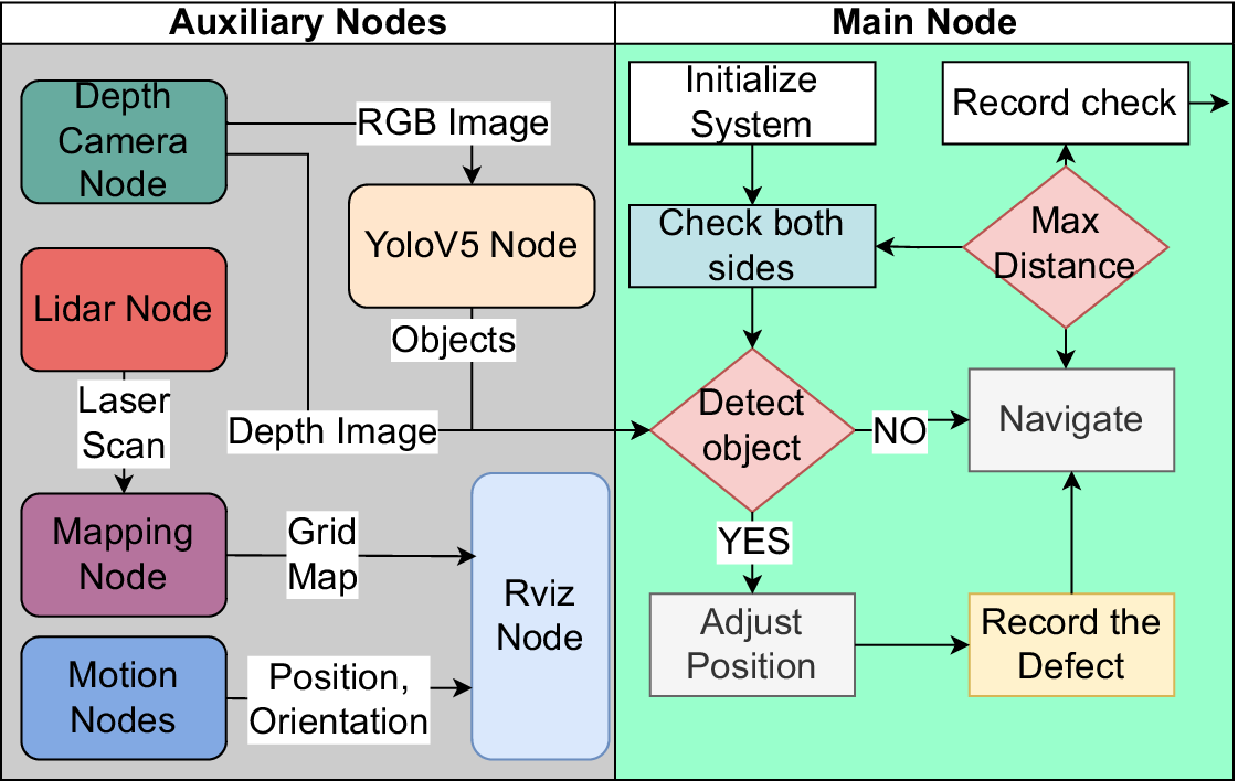
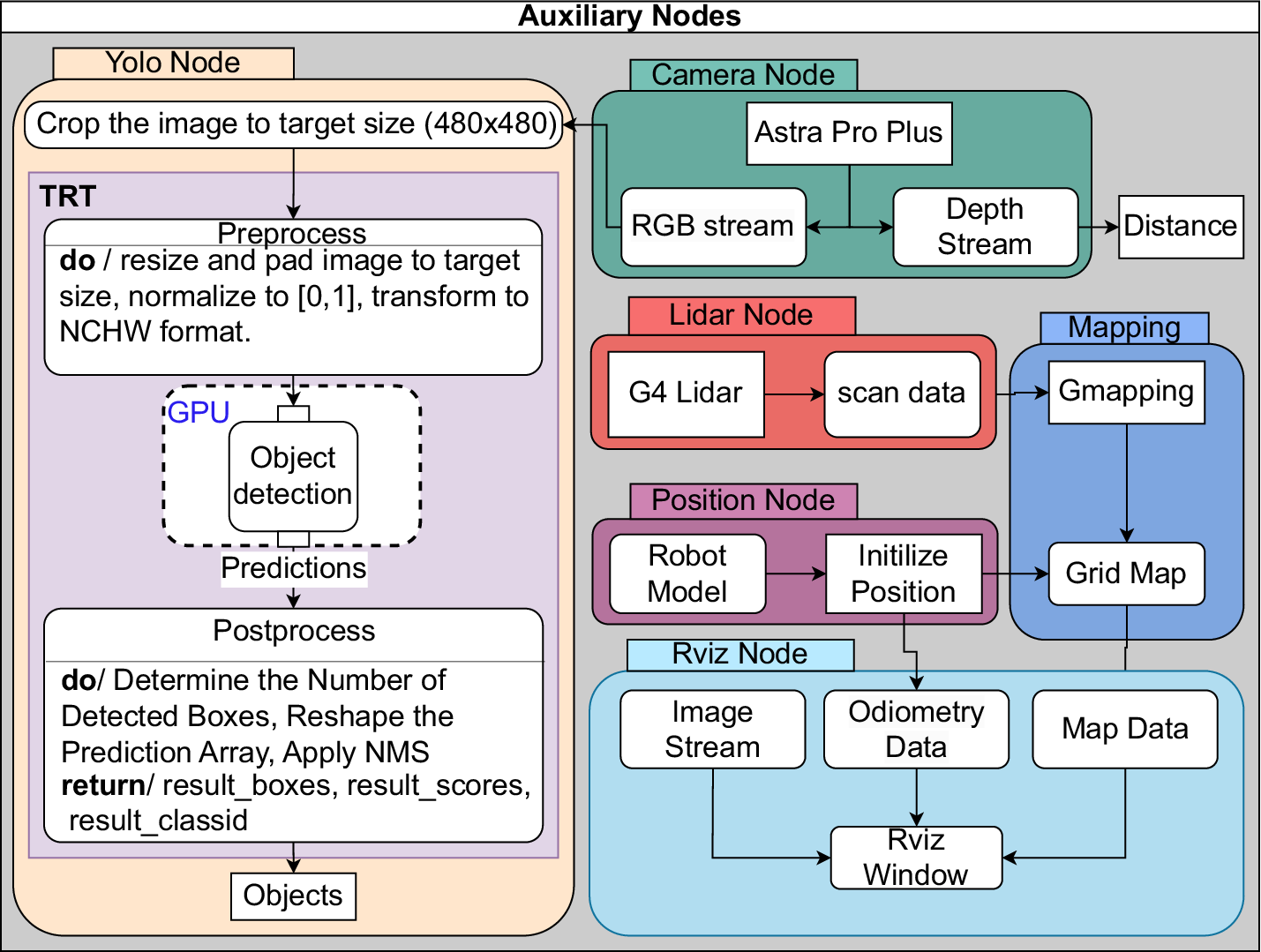
Figure 5 illustrates the workflow of the autonomous inspection system consists of a main node and auxiliary nodes. The main node serves as the robot’s core controller, while the auxiliary nodes integrate multiple functional nodes, including the depth camera node, the LiDAR node, the position node, the RViz node, and the YOLO node. In the following, the components and functionalities of both the main and auxiliary nodes are explained in detail.
Workflow of the autonomous inspection system using depth camera, LiDAR, and AI-based object detection for damage assessment, including position adjustment before recording damage.

2.3.1. Main node
As shown in Figure 5, the main node acts as the robot’s core controller, directing and coordinating the actions of all other nodes to ensure accurate and effective inspection. It controls the robot’s movement, damage detection, and position adjustment in addition to initialising all subsystems.
The auxiliary nodes, including the camera, LiDAR, YOLO, and mapping nodes (see Figure 5), are provided by existing robot technology. These nodes handle specific tasks such as sensor data acquisition, object detection, and environment mapping. The main node starts by activating all the auxiliary nodes. Each subsystem is checked to ensure readiness before proceeding with the inspection workflow.
As can be seen in Figure 6, the initial scanning process involves the robot systematically evaluating potential damage by adjusting the camera position to each side with a 90° angle and analysing the results, as outlined in the following steps:
-
1. To begin, the robot sets the camera position to the left and looks for damage in its range of vision.
-
2. If no damage is detected, the camera turns to the right and scans again.
-
3. If no cracks are found with a confidence score greater than the given threshold, the camera returns to the front position, and the robot starts navigating.
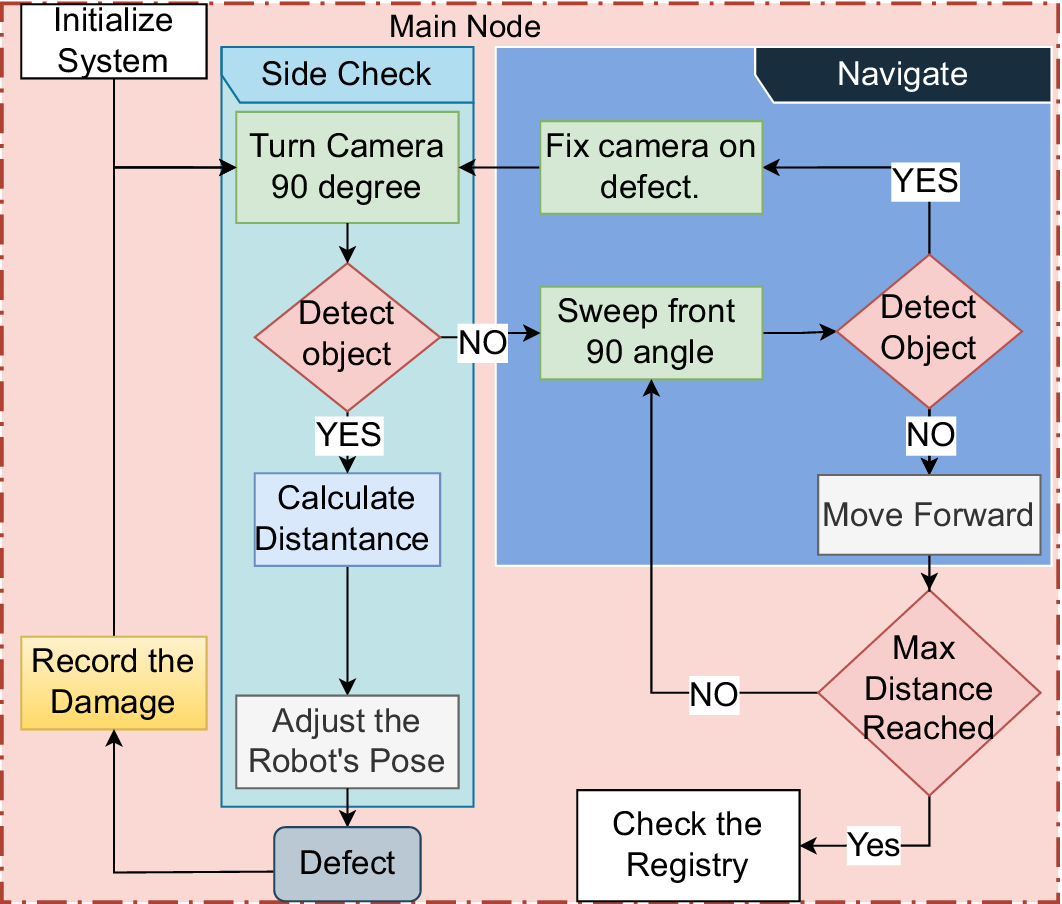
Detailed methodology of the main node in the autonomous inspection system, including object detection, position adjustment, damage recording, and navigation control.

As shown in Figure 6, during navigation, the robot continuously performs sweeping motions with the camera, analyzing its surroundings for damage. When damage is detected while navigating, the following sequence is activated:
-
1. The robot calculates the angle of the crack’s center relative to its position.
-
2. The camera turns to align with the center of the crack, adjusting its servo angle to point at the damage.
-
3. The robot continues its forward motion, keeping the camera angle fixed on the crack.
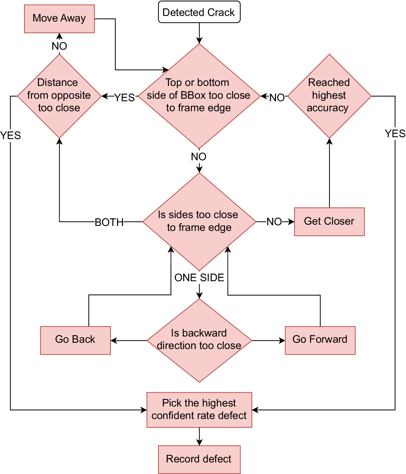
These three steps repeat until the angle of camera exceeds 75° and the robot aligns with the crack. Then, the robot rotates the camera to 90° toward the crack and begins adjusting its position to capture detailed images (see Figure 7). Pose adjustment is a critical phase to ensure that the damage is properly framed for documentation. The robot follows these steps:
-
1. The robot checks each edge of the bounding box of damage. If no edge is in the frame, take appropriate action:
-
(a) Handling left or right edge out of frame: If the left or right edge of the bounding box is not visible, the robot adjusts its position by moving forward or backward. This is because the camera is oriented at an angle relative to the robot’s forward-facing direction, allowing lateral adjustments to bring the missing edge into the frame.
-
(b) Handling both left and right edges out of frame: If both the left and right edges are out of frame, it indicates that the robot is too close to the wall. In this case, the robot moves away from the wall to ensure the entire bounding box is visible. However, if the robot cannot move further back and both edges remain out of frame, it retraces its path to locate the starting point of the crack. Once the starting point is identified, the robot begins recording and moves forward, capturing multiple images to document the entire extent of the damage.
-
(c) Handling top or bottom edge out of frame: If the top or bottom edge of the bounding box is out of frame, the robot moves away from the wall to adjust its position and bring the missing edge into view. If further adjustment is not possible (e.g., due to physical constraints), the robot records the crack in its current state.
-
-
2. If the robot is able to fit every edge in the frame, it generates a temporary object that records the damage’s image, bounding box, location, and area.
-
3. While the robot is in motion, it maintains a buffer containing the three damage objects with the highest detection confidence. For every new frame of the same damage instance, the buffer entry is updated if the new observation has (i) a higher confidence score or (ii) a larger visible area. This allows the robot to refine each damage record before committing it to permanent memory. At the end of the process, the version with the highest confidence score is stored permanently, even if a previous frame offered a larger visible area.
-
4. The robot uses a YOLO-based model to detect cracks, which assigns a confidence score to each detection. A minimum threshold of 0.5 is applied to filter out unreliable predictions. During operation, the robot continually evaluates successive frames of the same damaged object and retains the one with the highest confidence score. The process stops once no higher confidence score is detected after a given number of frames or distance traveled, indicating that the optimum observation has likely been reached.
Flowchart illustrating the adaptive pose adjustment process for crack detection. The robot iteratively refines its position based on bounding box proximity to frame edges and confidence scores, ensuring optimal crack visibility before capturing detailed images.

These procedures are repeated until the robot approaches the wall at a distance shorter than 15 cm, which is the minimum threshold required for the depth camera to accurately measure distance or until it is determined that the adjustments made do not improve the confidence rate. If any of these requirements are met, the system transfers the location, time, confidence score, bounding box, and damage snapshot from temporary to permanent memory. The robot then continues its navigation to identify and detect additional instances of damage.
As illustrated in the workflow in Figure 6 the inspection process terminates when the robot attains the predefined maximum inspection distance. Upon reaching this threshold, the system performs a final validation of temporary data registries to mitigate potential data loss caused by occlusions or dynamic prioritization of cracks during navigation. Cracks exceeding a confidence threshold, identified but not yet archived due to transient sensor limitations or algorithmic focus shifts, are systematically preserved to ensure comprehensive damage documentation. This protocol guarantees robust data integrity before concluding the inspection cycle.
2.3.2. Sensor nodes
The LiDAR node (Section 2.2.4) processes raw laser scan data and transforms it into a structured format that can be efficiently used by other nodes in the system. It filters, interprets, and organizes distance measurements to ensure the data is accurate and accessible for downstream tasks. As can be seen in Figure 1, the processed laser data are sent to the main node (Section 2.3.1) for obstacle avoidance. Meanwhile, the LiDAR node provides refined distance data to the mapping node (Figure 2.3.5), enabling Gmapping algorithm (Grisetti et al., Reference Grisetti, Stachniss and Burgard2007) to create detailed environmental maps.
The depth camera node (Section 2.2.3) is responsible for converting the sensors’ raw RGB and depth data into usable information before transmitting it to the main node (see 2.3.1). The RGB stream is directed to the YOLO node (Section 2.3.4), where it is used for damage detection (see Figure 8). The depth data are analyzed by the main node to provide accurate distance measurements to the detected damage.
Detailed architecture of the auxiliary nodes.

Other sensor nodes, such as the IMU node and odom node, work together to provide the robot with a comprehensive understanding of its position, orientation, and kinematic state. These nodes integrate data from inertial sensors, motor encoders, and localization systems to track the robot’s movement, publish its real-time state, and ensure accurate coordination of its components.
2.3.3. Position node
The position node uses odometry data to track the robot’s path and records its position and orientation. This information is published to the main node, enabling it to determine the spatial coordinates of detected cracks. By maintaining accurate positional data, the system ensures that cracks identified by the YOLO node are associated with their precise locations, facilitating efficient reporting and reconstruction of as-is digital models. Additionally, the system uses a temporary crack registry to track detected damage instances (see Section 2.4, preventing redundant inspections by recognizing previously recorded cracks.
2.3.4. Yolo node
The robot’s real-time object detection algorithm is based on the YOLOv5 model, which is used for rapid and accurate crack identification. This system operates with minimal latency, efficiently detecting potential cracks and generating bounding boxes around damage areas for further analysis (see Figure 9). To enhance the detection accuracy for different structural surfaces, the model was trained on two distinct datasets, each tailored for specific material types.
Overview of the YOLOv5-based crack detection pipeline with GPU-accelerated inference. The pipeline consists of three main stages: preprocessing, where images are resized, padded, and normalized; inference, performed on a GPU using a TRT-optimized YOLOv5 model; and post-processing, where the final detection results are extracted using non-maximum suppression (NMS).

The first dataset, Concrete Defects (Multiverse, 2023), consists of 1239 annotated images depicting various types of cracks on concrete surfaces. This dataset plays a crucial role in enabling the model to recognize crack patterns typically found in retaining walls and other concrete-based structures. The annotated images include defects such as surface fractures, deep fissures, and irregular cracking patterns, ensuring that the trained model can generalize well across different real-world conditions.
The second dataset, MCrack1300 (Ye et al., Reference Ye, Lovell, Faramarzi and Ninić2024), is specifically designed for masonry structures. It provides annotated images of cracks on brick and stone walls, addressing the unique texture and failure patterns present in these materials. Unlike concrete cracks, which often exhibit linear or web-like formations, masonry cracks can follow mortar joints, form stair-step patterns, or result from material separation. Incorporating this dataset into the training process significantly improves the model’s ability to distinguish actual structural damage from natural separations between bricks.
To enhance the model’s generalization across different structural materials, both datasets were merged and trained together as a single dataset. The MCrack1300 dataset contributed 1000 images for training, while the Concrete Defects dataset provided 1239 training images, resulting in a total of 2239 training images. The ratio of masonry to concrete images in the combined dataset is approximately 1:1.24, ensuring a balanced representation of both material types. Merging these datasets provides several advantages: (1) it allows the model to learn diverse crack formations, making it more robust when detecting cracks on different surfaces; (2) it improves the model’s adaptability to varying lighting conditions and textures; and (3) it reduces dataset bias by ensuring a more comprehensive range of crack appearances.
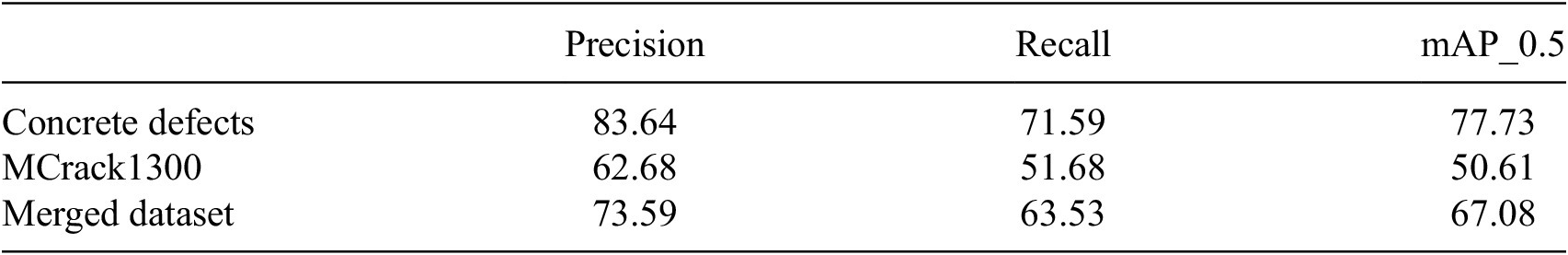
Finally, the model’s performance was evaluated on three separate datasets: Concrete Defects, MCrack1300, and the Merged Dataset, with results summarized in Table 1. The results indicate that the model achieved the highest performance when trained and tested on the Concrete Defects dataset, with a precision of 83.64% and a mean average precision at a 0.5 threshold (mAP_0.5) of 77.73%, suggesting that it effectively detects cracks in concrete surfaces. However, the performance on the MCrack1300 dataset was significantly lower, with a precision of 62.68% and an mAP_0.5 of 50.61%, highlighting the challenges of detecting cracks in masonry structures. This can be attributed to the model’s limited exposure to masonry-specific cracks during training and the inherent complexity of distinguishing cracks from mortar joints and natural separations in brick walls.
Performance evaluation of the trained model on different datasets

Note: The table presents precision, recall, and mean average precision (mAP_0.5) for the model trained separately on the Concrete Defects dataset, the MCrack1300 dataset, and the merged dataset.
Training on the merged dataset provided a balanced improvement, with a precision of 73.59% and an mAP_0.5 of 67.08%, demonstrating enhanced generalization across both concrete and masonry surfaces. While the performance was slightly lower than the concrete-only model, it represents a more adaptable solution for real-world applications where both material types are present. These results emphasize the benefits of dataset diversification in improving crack detection across different structural conditions.
Upon activation of the main node, the YOLO node is initialized immediately and processes RGB images supplied by the camera node. To ensure efficient GPU utilization, these images are processed through an optimized workflow leveraging TRT (TensorRT) (NVIDIA Corporation, 2023) and pre-compiled engine files. TRT is a deep learning inference library developed by NVIDIA and optimized to run neural networks on GPUs. A serialized version of the TRT-generated optimized model is called an engine file. It contains every layer, weight, and configuration required to run the YOLO model effectively on the GPU. The engine file is customized to the particular hardware it is producing on in order to guarantee optimal performance during inference. This workflow enhances inference speed and accuracy, ensuring real-time performance suitable for demanding operational environments.
For robotic systems to identify damage in real-time, asynchronous processes are essential to the inference process. They make it possible for several tasks to be completed simultaneously without affecting the main thread, which is crucial for preserving system efficiency and responsiveness. In our case, these tasks include processing sensor input, running detection algorithms, and making decisions in real-time.
In YOLOv5, the confidence score for each detected object is computed automatically by the model as the product of two values: the objectness score and the class probability $ P\left(\mathrm{class}|\mathrm{object}\right) $
. The objectness score reflects the model’s confidence that a bounding box contains any object, while the class probability represents the likelihood that the object belongs to a specific class (e.g., a crack). During inference, YOLOv5 outputs this combined confidence score for each predicted bounding box. In the second inspection scenario, the increase in confidence scores suggests that pose adjustment led to better bounding box alignment and stronger classification certainty, resulting in more reliable crack detection.
$ P\left(\mathrm{class}|\mathrm{object}\right) $
. The objectness score reflects the model’s confidence that a bounding box contains any object, while the class probability represents the likelihood that the object belongs to a specific class (e.g., a crack). During inference, YOLOv5 outputs this combined confidence score for each predicted bounding box. In the second inspection scenario, the increase in confidence scores suggests that pose adjustment led to better bounding box alignment and stronger classification certainty, resulting in more reliable crack detection.
The YOLO node follows a systematic workflow (see Figure 9) that includes pre-processing, inference, and post-processing to extract the optimal bounding boxes from the input RGB images:
-
1. Preprocessing: In the preprocessing step for TRT, the raw image is prepared for loading onto the GPU to perform damage detection. As part of this process, the image is transformed into the NCHW format, which represents the following dimensions: batch size (N), number of channels (C), depth (D), height (H), and width (W). This format is widely used for storing multidimensional arrays, data frames, or matrices in memory, where the data can be efficiently represented as a one-dimensional array. The NCHW format is particularly advantageous for GPU-based computation because it aligns the data layout with the memory access patterns optimized for deep learning operations. The GPU can process the data more effectively by organizing it in this way, which guarantees quicker computation and lower latency during inference.
-
2. Inference: As shown in Figure 8, the preprocessed image data is transferred from the host (CPU) to the GPU memory using an asynchronous operation that utilizes a stream for non-blocking data transfer. The used approach optimizes throughput by reducing idle time and enabling simultaneous operation of the CPU and GPU. The inference process is initiated by executing the TRT model on the GPU. Using the input bindings and stream, the GPU processes the data through the model’s computational layers to generate predictions.
-
3. Post-processing: The raw predictions generated by the TRT model undergo a series of post-processing steps to refine the results and extract actionable data. The system first determines how many bounding boxes were found in the image overall. In order to make it easier to manipulate and analyze bounding box coordinates and confidence scores, the raw predictions are then transformed into a structured and easily interpretable format. Specifically, the TRT model outputs a tensor of shape $ \left(B,N,7\right) $
, where
$ B $
represents the batch size,
$ N $
is the number of predictions, and the seven values include the bounding box coordinates, confidence scores, and class probabilities. The confidence score, which indicates the likelihood that a bounding box contains a crack, is computed as the product of the objectivity score and the predicted class probability. The objectivity score is obtained by applying the sigmoid function to the raw objectivity outputs, ensuring the value falls between 0 and 1:
$ \left(B,N,7\right) $
, where
$ B $
represents the batch size,
$ N $
is the number of predictions, and the seven values include the bounding box coordinates, confidence scores, and class probabilities. The confidence score, which indicates the likelihood that a bounding box contains a crack, is computed as the product of the objectivity score and the predicted class probability. The objectivity score is obtained by applying the sigmoid function to the raw objectivity outputs, ensuring the value falls between 0 and 1:


 $$ P\left(\mathrm{object}\right)=\sigma (s)=\frac{1}{1+{e}^{-s}} $$
Since the model is trained for a single-class detection task, the class probability is also derived using the sigmoid function:
 $$ p=\sigma (c)=\frac{1}{1+{e}^{-c}} $$
where $ c $
is the raw class score output by the model. The sigmoid function serves two critical roles: it normalizes unbounded raw scores into probabilistic values within [0,1], enabling meaningful confidence interpretation; and its non-linear compression amplifies score distinctions near decision boundaries, enhancing sensitivity to marginal detections. The final confidence score is then computed as:
$ c $
is the raw class score output by the model. The sigmoid function serves two critical roles: it normalizes unbounded raw scores into probabilistic values within [0,1], enabling meaningful confidence interpretation; and its non-linear compression amplifies score distinctions near decision boundaries, enhancing sensitivity to marginal detections. The final confidence score is then computed as:
 $$ C=P\left(\mathrm{object}\right)\times p $$
To facilitate further processing, the bounding box coordinates, originally in center-based format are converted to corner-based format, which is more commonly used for object detection tasks.
Then, only bounding boxes with the highest confidence ratings for each detected object are kept after redundant ones are removed using NMS. By successfully eliminating overlapping detections, this phase lowers the possibility of false positives and increases the detection process’s overall reliability. The improved bounding boxes are then extracted for additional usage, together with the class labels and confidence scores that go with them.
2.3.5. Mapping node
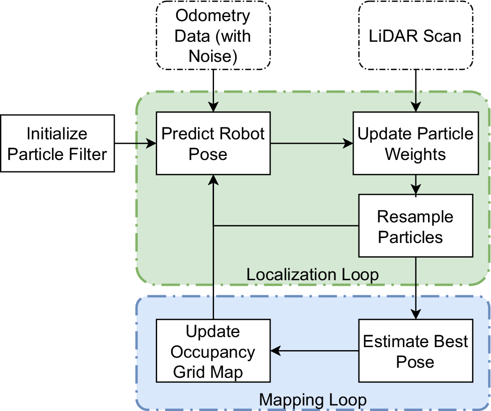
The Gmapping algorithm (Grisetti et al., Reference Grisetti, Stachniss and Burgard2007), based on the SLAM (Whyte, Reference Whyte2006) approach is used to create a map of the environment. Figure 10 illustrates the process flow of the algorithm, which uses LiDAR scans to gather data on the surroundings and integrates odometry data obtained from wheel encoders, inertial measurement units (IMUs), or other sensors, to enhance localization. These data are then processed to identify landmarks and features, which are then used to update both the map and the robot’s position. The algorithm typically includes two main processes: localization, which estimates the robot’s position and orientation, and mapping, which updates the map with new information.
Process flow of the Gmapping algorithm. The algorithm integrates LiDAR scans and odometry data to estimate the robot’s pose and update the map.

As shown in Figure 10, the localization loop in the Gmapping algorithm relies on a particle filter (Djuric et al., Reference Djuric, Kotecha, Zhang, Huang, Ghirmai, Bugallo and Miguez2003), which iteratively performs prediction, update, and resampling steps to estimate the robot’s pose. This process refines localization by integrating odometry and LiDAR data, ensuring that the most probable robot positions contribute to map updates, making Gmapping effective in environments with high uncertainty and noise, such as geotechnical sites surrounded by vegetation. This continuous process allows for real-time navigation and mapping.
The particle filter has the following steps:
-
1. Initialization: A collection of particles, or samples, is created, each of which represents a possible system state, such as the orientation and location of the robot.
-
2. Prediction: Each particle moves according to a motion model, which forecasts the next state based on the current state and control inputs, such as the movements of the robot.
-
3. Update: The weights of the particles are updated using sensor measurements. Higher weights are given to particles that more closely match the sensor data.
-
4. Resampling: Depending on their weights, particles undergo a resampling process. Higher-weighted particles have a greater chance of being chosen, but lower-weighted particles are likely to be eliminated. This stage guarantees that the most likely states receive the majority of the computing resources.
-
5. Iteration: The process is iterated, with particles continuously predicted, updated, and resampled as new sensor data becomes available.
2.3.6. Rviz node
For tracking the robot’s activities, the RViz node offers a real-time visualization interface, as illustrated in Figure 11. It shows sensor data, including LiDAR scans, grid maps, and it visualizes the robot’s location and path through the surroundings. On the basis of real-time feedback, it also enables operators to step in or make modifications.
Visualization of the robotic inspection system in RViz, showcasing the robot model, sensor data, and navigation path.

2.4. Damage recording
If specific conditions are met, the system permanently stores relevant information, including the image, confidence score, location, and bounding box, ensuring efficient crack tracking while conserving time and resources.
Upon detection of damage, an initial object is instantiated to represent the identified crack. To efficiently track detected cracks, the system maintains a temporary crack registry a dynamically updated list storing objects corresponding to detected damage instances. The robot’s trajectory up to the point of detection is recorded (Section 2.3.3), enabling precise localization of the damage. Using data from the depth camera, the distance between the robot and the structure (e.g., retaining walls or tunnel walls) where the damage is located in the real world is measured. This measurement facilitates the localization of the damage on a two-dimensional coordinate system, with the coordinates being stored in a temporary registry.
Using camera indices, the size of the detected crack in the real world is measured and recorded in the registry. The system checks if the centroid of a newly detected crack falls within the area of a previously recorded crack. If it does, the crack is considered redundant and is not recorded again, ensuring efficient tracking of unique damage instances.
Building on this foundation, the robot employs an iterative position adjustment mechanism to enhance the confidence score of the damage detection process (see Figure 4). This mechanism dynamically refines the robot’s position relative to the target surface, optimizing the quality of the captured images and the accuracy of the detection. Throughout this process, the confidence score is continuously monitored, evaluated, and updated in the robot’s temporary crack registry. The system intelligently determines the optimal stopping point for the iterative adjustments, which occurs either when the confidence score plateaus, indicating no further improvement, or when the robot approaches the surface too closely, the minimum threshold required for the depth camera to accurately measure, or loss of perspective.
Once the optimal stopping condition is met, the system stores the image capturing the damage with the highest achieved confidence score to disk. This archival process includes comprehensive metadata, such as the precise timestamp of the capture, the final confidence score, the cracks’ positional data, and the bounding box coordinates of the detected damage at the moment of capture. Importantly, this approach not only ensures the collection of high-quality, reliable data but also inherently generates accurate labels for the detected damage, as the metadata and bounding box information are automatically recorded alongside the image. This eliminates the need for manual or post-processing labelling, streamlining the data collection pipeline and reducing potential human error.
3. Case study
3.1. Verification
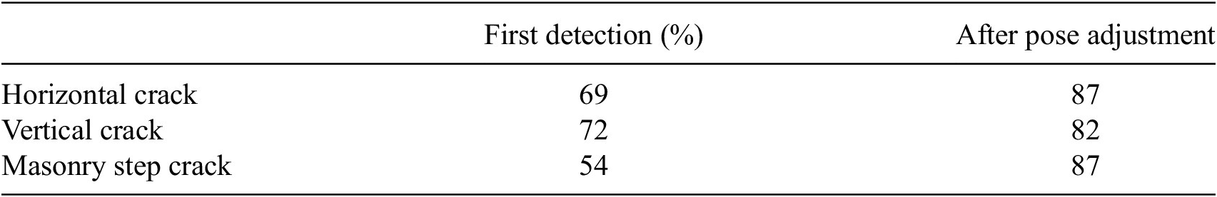
Verification was conducted in a controlled indoor environment, including a narrow corridor, prior to real-world testing. Auxiliary damages were introduced on vertical surfaces to facilitate evaluation. Specifically, cracks extracted from printed sheets were carefully cut out and adhered to foam boards, which were then strategically positioned in various configurations across the office space. These synthetic cracks were incorporated into the test portion of the dataset. The experiment included crack detection on both masonry and concrete surfaces to evaluate the robot’s performance across different materials, as can be seen Figure 12. The robot’s ability to manoeuvre automatically in this setting, identify cracks, change its location, and identify these cracks at more accurate angles was tested. During the validation process, the robot successfully detected artificial cracks. It automatically manoeuvred to capture the image from the optimal viewpoint. When comparing the initial damage identification to the state after pose modification, there is an improvement in confidence of 18%, as shown in Figure 13. Although exposure correction generally slows down the process, the average increase in confidence for more then 20% (see Table 2) compensates for the additional time required.
Verification experiment in a controlled indoor environment. The robot navigates a narrow corridor while detecting artificially introduced cracks on foam board walls. The experiment includes crack detection on both masonry and concrete surfaces to evaluate the robot’s performance.

Test on verification environment.

Confidence rate improvement after pose adjustment for different types of cracks

Note: The table compares the confidence levels of the first detection with those obtained after pose adjustment.
To further evaluate the necessity of pose adjustment, a comparative experiment was conducted. Fifteen artificial crack samples were mounted on a single wall, and the robot was positioned 1 meter away, as can be seen in Figure 14, traversing the wall without utilizing pose adjustment. While this approach successfully detected cracks in most cases, its efficacy proved highly dependent on crack size. Cracks smaller than 6 cm consistently fell below the detection threshold and were missed entirely. Furthermore, cracks exceeding the camera’s field of view were partially detected; however, the inability to capture the entire crack within a single frame prevented accurate size quantification.
Verification experiment for one side wall in a controlled indoor environment.

Figure 15 compares the crack detection results from two inspection scenarios. The top row illustrates the first case without pose adjustment, while the bottom row presents the second case with pose adjustment. In both scenarios, the object detection model consistently identifies most cracks; however, notable differences in detection coverage and confidence are observed. In the first case, the model failed to detect cracks numbered 2, 3, and 13. In contrast, the second case successfully detected 14 cracks, with only crack number 3 missing. Furthermore, the confidence scores for most detected cracks increased in the second case, indicating improved detection reliability.
Experimental verification: comparing detected crack results without and with pose adjustment.

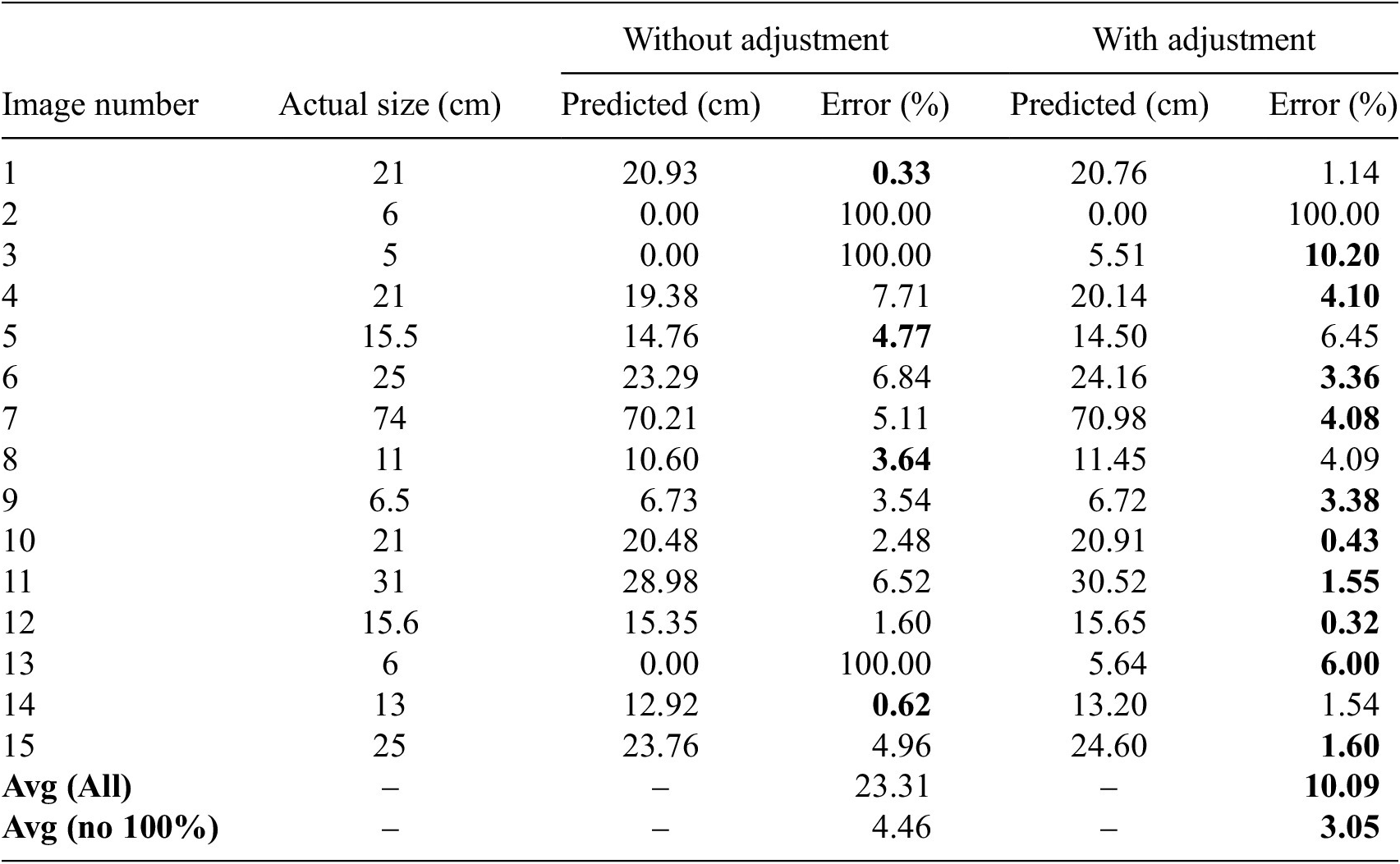
Table 3 presents a quantitative comparison between actual crack sizes and the sizes detected by the system, both with and without pose adjustment. The results highlight the limitations of fixed-viewpoint inspection. In the baseline scenario without pose adjustment, three cracks (samples 2, 3, and 13) were not detected at all, resulting in a 20% failure rate. All of these missed cracks were smaller than 6 cm, which indicates that the system struggled to detect small cracks due to low resolution and insufficient confidence.
Comparison of detected crack sizes with actual sizes

Note. Comparison of detected crack sizes with actual sizes, with the best accuracy highlighted in bold.
When the experiment was repeated with pose adjustment enabled, starting from the same initial distance, most of these limitations were effectively mitigated. The system was able to identify potential regions of interest, even for sub-5 cm cracks, which triggered autonomous approach maneuvers. By reducing the distance to the target, the robot increased both feature resolution and signal-to-noise ratio, allowing these smaller cracks to exceed the confidence threshold for detection. For instance, sample 3, which has an actual size of 5 cm, was successfully detected at 6 cm with pose adjustment, although it was completely missed without it.
For cracks that were too large to fit within a single frame, the robot autonomously moved backward to capture the entire crack in view. This allowed for more accurate measurements that were closer to the actual sizes, as seen in samples 6 and 7. In addition, the pose adjustment process served as a secondary validation mechanism. If the confidence did not improve during the robot’s movement, the region was discarded to avoid false positives.
Overall, the adaptive approach significantly improved detection performance. With pose adjustment, only one crack remained completely undetected, reducing the failure rate from 20% (3 out of 15) to 6.66% (1 out of 15). Additionally, the average error rate dropped from 23.31% to 10.09%, and further down to 3.05% when excluding total misses. While not achieving perfect accuracy, pose adjustment clearly enhanced the system’s ability to detect and measure cracks more reliably, especially smaller ones.
3.2. Real-world testing
For the testing phase, several retaining walls and Masonry tunnels located in Birmingham/UK were selected based on accessibility, suitability for evaluation, and diversity in construction materials, including masonry, concrete and stone. The selection process aimed to ensure variability in crack types and structural conditions, enabling a comprehensive assessment of the system’s performance across different scenarios.
The robot autonomously navigated next to the tunnel wall and retaining walls while capturing real-time visual data and identifying crack patterns without human intervention. As shown in Figure 16, the robot is positioned inside the tunnel, demonstrating its capability to navigate and perform inspections in such environments.
The robot conducting tunnel inspection, capturing real-time visual data, and detecting crack formations along the tunnel walls.

A field test for demonstrating the effectiveness on real-world examples was conducted on retaining walls and tunnels, confirming the operational necessity of pose adjustment for reliable crack detection. Under field conditions characterized by irregular surfaces, variable lighting, and complex geometries, static inspection methods frequently failed to detect fine cracks or accurately quantify large cracks. As evidenced in Figure 17, these limitations manifested as both missed detections and inaccurate size measurements. Conversely, when pose adjustment was enabled, the robot dynamically optimized its viewpoint: approaching to resolve small cracks and retreating to capture expansive cracks in their entirety.
Comparison of crack detection performance without and with pose adjustment. Each pair of images shows the same scene: the left image presents the crack detection results without pose adjustment, while the right image shows improved detection after applying pose adjustment.

In real-world testing, obtaining precise ground truth annotations for cracks is challenging due to environmental variability and the complexity of crack shapes. Therefore, in our paper, quantitative evaluation is based on comparing the estimated crack sizes rather than pixel-level accuracy. In several instances, the model successfully detects portions of the cracks. Therefore, assessing the detected crack length provides a fair metric for performance evaluation. For instance, in Figure 17(b), the actual crack length is approximately 60 cm. Without pose adjustment, the model detects a crack length of only 14 cm, while with pose adjustment, the detected length improves significantly to 47 cm.
Finally, as observed in Figure 18, the robotic system successfully identified various types of cracks on both retaining walls and tunnel walls, in masonry and concrete structures, demonstrating the system’s applicability in challenging real-life conditions. Figure 18 displays a comparative visual analysis of crack detection performance across three setups: original images (left), detection without pose adjustment (middle), and detection with pose adjustment (right). The annotated measurements below each image indicate either the actual crack size or the size detected by the model. Notably, without pose adjustment, several cracks were missed entirely, such as those in rows 1, 2, and 5. In contrast, the system with pose adjustment successfully detected these cracks, although sometimes only partially. For example, in row 1, the crack detection improved from 0 cm to a combined 27 cm with pose adjustment, and in row 3, detection increased from 28 cm to a near-complete 123 cm. Furthermore, the number of detected cracks also improved. For instance, in row 6, three separate crack segments were recognized after pose alignment. Confidence scores generally increased alongside detection quality, suggesting the model’s improved certainty in identifying damage.
Original images (left), detection results without pose adjustment (middle), and detection results with pose adjustment (right).

Despite these improvements, the pose adjustment strategy introduced context-specific false positives. Masonry walls proved particularly vulnerable: the algorithm’s low preliminary confidence threshold, which was designed to capture potential cracks, frequently misinterpreted mortar joints and brick interfaces as defects, triggering unnecessary inspections. Similarly, vegetation on walls occasionally registered as cracks due to textural similarities. While most false candidates were filtered during repositioning as confidence gains fell below the validation threshold, notably in high-contrast lighting cases, they exceeded the confidence threshold even after adjustment. Although plant-induced errors impacted both methods to a similar extent, an increase in false positives related to mortar joints was observed in the pose adjustment approach. This increase can be explained by the exploratory behavior of the pose adjustment mechanism, which initially employs a lower detection threshold (0.3) to broaden the search space and capture more potential detections. In the early stages, this may lead to a higher number of false positives. However, as the viewpoint is refined and the detection confidence is reassessed, only predictions exceeding a higher saving threshold (0.5) are retained. Therefore, despite a temporary rise in false positives during the initial exploration, many of these are ultimately discarded if they do not meet the final confidence requirement.
In structural health monitoring, the consequences of undetected damage significantly outweigh the burdens of false positives. Industry standards prioritize comprehensive defect identification because missed cracks accelerate hidden deterioration that compromises structural integrity, while false positives merely necessitate verification efforts. Our methodology reflects this safety-first principle, where tolerance for limited false positives ensures sub-critical defects aren’t overlooked. This operational tradeoff is justified when considering that false positives can be resolved through secondary inspection, whereas undetected cracks eliminate intervention opportunities entirely.
4. Conclusion
This paper presents the successful implementation of an autonomous robotic system for detecting structural cracks in retaining walls and masonry tunnels. By employing an AI-based approach, combining a robotic platform with embodied intelligence and a deep learning-based damage detection model, the system accurately identified various types of cracks. Experimental results demonstrate the system’s ability to reduce reliance on manual inspection, while improving consistency, confidence, and measurement accuracy in both controlled and real-world environments.
The primary contributions of this study are:
-
• The proposed framework is fully autonomous and capable of real-time structural crack detection without human intervention. By integrating adaptive pose adjustment, the system dynamically repositions itself based on crack size and confidence levels. This process led to an average increase in detection confidence of 18%, with gains exceeding 20% for certain crack types, significantly enhancing reliability in challenging conditions.
-
• The automated recording and labelling of detected cracks supports continuous improvement of deep learning models for structural health monitoring. This functionality lays the foundation for predictive maintenance strategies and scalable infrastructure inspection solutions.
-
• The system records detected cracks along with their precise location and timestamp, allowing for temporal tracking of structural changes. In real-world tunnel inspections, the adaptive approach enabled the detection of cracks previously missed due to size or field-of-view limitations. For instance, detection of a 60 cm crack improved from 14 cm to 47 cm after pose adjustment, illustrating the system’s accuracy and adaptability in complex environments.
-
• The experimental results confirm that pose adjustment significantly improves detection accuracy. Without pose adjustment, the average size estimation error was 23.31%, and three out of 15 cracks were completely missed. With pose adjustment, the error rate dropped to 10.09% and just 3.05% when excluding missed detections, while reducing the number of undetected cracks from 3 to 1. This not only demonstrates increased measurement accuracy but also confirms that adaptive positioning enhances the robot’s ability to detect fine cracks and large defects with higher confidence.
While the proposed system demonstrates significant potential in autonomous damage detection, it has certain limitations. One is the model capability: the system uses YOLOv5, which is integrated into the robot’s onboard processing unit due to its real-time performance advantages. However, YOLOv5 is not the most advanced deep learning model available for crack detection, and its performance can be inconsistent. In some cases, it fails to detect fine cracks or misclassifies non-crack features, for instance, natural separations between bricks in masonry walls may be erroneously identified as cracks. These misdetections highlight the need for more specialized models or additional post-processing techniques to improve reliability.
Another limitation is the camera positioning constraints. Although the robot’s camera can rotate 240 degrees horizontally, it lacks vertical movement since it is not mounted on a servo motor that allows upward or downward adjustments. As a result, cracks located on the upper or lower sections of retaining walls or tunnel surfaces may be difficult to capture effectively. The inability to reposition the camera in the vertical axis restricts the system’s coverage, potentially leading to incomplete crack assessments in certain scenarios.
In future work, the framework’s damage detection capabilities could be enhanced by integrating cloud-based computational models. Streaming real-time sensor data to these systems would enable advanced segmentation, classification, and structural integrity assessments, improving diagnostic accuracy. Additionally, deep reinforcement learning (DRL) could refine the robot’s autonomy by enabling adaptive navigation and data collection strategies. Such algorithms would allow the system to optimize inspection workflows in dynamic environments, reducing reliance on predefined rules. Finally, embedding 3D spatial mapping would correlate detected damages with structural geometry. This integration would facilitate holistic damage contextualization, aiding engineers in prioritizing maintenance interventions and resilience planning.
Acknowledgements
The computations described in this research were performed using the Baskerville Tier 2 HPC service (https://www.baskerville.ac.uk/). Baskerville was funded by the EPSRC and UKRI through the World Class Labs scheme (EP/T022221/1) and the Digital Research Infrastructure programme (EP/W032244/1) and is operated by Advanced Research Computing at the University of Birmingham. The computations described in this paper were also performed using the University of Birmingham’s BlueBEAR (http://www.birmingham.ac.uk/bear) HPC service, which provides a High Performance Computing service to the University’s research community.
Special thanks to the Directorate General of Higher Foreign Education, Ministry of National Education of Türkiye, for providing Kamil Altinay with a full Ph.D. (education-related) scholarship.
The third author would like to acknowledge funding by the UK Research and Innovation (UKRI) [grant agreement No: 101086413, EP/ Y003586/1], as a guarantee for the European Union HORIZON-MSCA-2021-SE-01 [grant agreement No: 101086413] ReCharged—Climate-aware Resilience for Sustainable Critical and interdependent Infrastructure Systems enhanced by emerging Digital Technologies.
We would like to thank Jianyu Zhang for his assistance in illustrating the robot’s autonomous structural inspection process. His expertise in 3D modeling and visualization using Blender significantly contributed to the graphical representation of our methodology.
Author contribution
Conceptualization: K.A., J.N.; Methodology: K.A., Z.Y., J.N.; Software: K.A., Z.Y.; Data curation: K.A., Z.Y.; Formal analysis: K.A.; Visualization: K.A.; Writing—original draft: K.A., Z.Y.; Writing—review and editing: J.N., S.-A.M.; Supervision: J.N., S.-A.M.; Resources: J.N. All authors approved the final submitted draft.
Competing interests
The authors declare none.
Data availability statement
The YOLOv5 model used for real-time crack detection was trained on two publicly available datasets to enhance its accuracy across different structural surfaces:
-
1. Concrete defects dataset: This dataset consists of 1239 annotated images for training various types of cracks on concrete surfaces (Multiverse, 2023). It helps the model recognize common crack patterns in retaining walls and other concrete-based structures. The dataset is available at https://universe.roboflow.com/multiverse-pvlsv/concrete-defects-44gvq.
-
2. Masonry dataset: Designed for masonry structures, this dataset includes 1000 annotated images of cracks on brick walls for training (Birmingham, 2024). It improves the model’s ability to differentiate structural damage from natural separations between bricks. The dataset is available at https://universe.roboflow.com/uni-of-birmingham/masonry.
Both datasets were used to fine-tune the detection model for different material types, ensuring robust crack identification in various real-world conditions. The code for the robot’s pose adjustment (Altinay, Reference Altinay2025) can be found in the project’s GitHub repository: https://github.com/abrekkamil/PoseAdjustment
Ethical standard
The research meets all ethical guidelines, including adherence to the legal requirements of the study country.


 Open access
Comments
No Comments have been published for this article.