Introduction
The cohesive properties of snow play an important role in the formation and movement of avalanches (Reference Bozhinskiy and LosevBozhinskiy and Losev, 1998). When the snow cover collapses and starts moving, it is the cohesive bonding of ice grains that facilitates the formation of hard, compact snow clods and granules that eventually compose the avalanche core (Fig. 1). The strength of the cohesive bonding is determined by the snow temperature and humidity, which therefore control the granule properties (Reference Voytkovskiy and BarteltVoytokskiy, 1977; Reference Bartelt and McArdellBartelt and McArdell, 2009) and subsequently the avalanche flow regime (Reference Gauer, Issler, Lied, Kristensen and SandersenGauer and others, 2008; Reference Issler and GauerIssler and Gauer, 2008; Reference Bartelt, Bühler, Buser, Christen and MeierBartelt and others, 2012a; Reference Naaim, Durand, Eckert and ChambonNaaim and others, 2013). Wet snow avalanches exhibit pronounced cohesive, visco-plastic-type flow behaviour (Fig. 1), in contrast to the non-cohesive and dispersive granular motion of dry snow avalanches, which are often accompanied by a powder cloud of suspended ice-dust. Although fundamental to a consistent understanding of avalanche motion, cohesion is rarely included in avalanche dynamics calculations (Reference Naaim, Naaim-Bouvet and FaugNaaim and others, 2003; Reference Wang, Hutter and PudasainiWang and others, 2004; Reference Pudasaini and HutterPudasaini and Hutter, 2007; Reference Christen, Kowalski and BarteltChristen and others, 2010).
The granular deposition field of a wet snow avalanche that occurred near Verbier, Switzerland, 13 March 2014. Many features of the deposits indicate the cohesive character of avalanche flows. These include the levee side walls at the edge of the forest (a), deposition steps in the flow interior (b), basal shear planes exposed by plug-like glide movements (b) and sintered particle agglomerates (a). Photographs: Francois Dufour and Cesar Vera Valero, SLF.

In this paper we introduce one additional model parameter to account for cohesion in avalanche flow. The model is based on actual shear and normal stress measurements with both wet and dry snow performed on the Swiss Weissfluhjoch experimental chute (Reference Platzer, Bartelt and KernPlatzer and others, 2007a,Reference Platzer, Bartelt and Jaedickeb). The model combines two classical definitions of cohesion (Reference RowlinsonRowlinson, 2002). Firstly, it acts as an additional shear stress in excess of the normal stress-dependent Coulomb shear resistance. This definition is common in soil mechanics applications, where cohesion is considered to arise in particle ensembles from either capillary stresses or discomfited granular geometries and packings (Reference MitchellMitchell, 1993). Cohesion then acts on the shearing processes in the avalanche core, especially in dense flows at low shear rates. Secondly, cohesion acts as an additional bonding potential to hinder volume expansion of the core. Cohesion therefore controls the avalanche flow density and thus, indirectly, the shear resistance and the flow height. These definitions of cohesion are based not only on the chute experiments, but also on the wide range of runout features found in avalanche deposits, especially in wet snow avalanche deposits, which often exhibit steep, cohesive side-walls and pile-ups (see Fig. 1) (Reference Jomelli and BertranJomelli and Bertran, 2001; Reference Miller, Adams, Schmidt and BrownMiller and others, 2003; Reference Bartelt, Glover, Feistl, Bühler and BuserBartelt and others, 2012b).
In the next section we introduce the concept of a representative volume V Φ in the avalanche core Φ (Fig. 2). Model equations, presented in the following section, describe how the volume V Φ changes under the actions of the basal shear and normal forces. Only then is it possible to describe how cohesion modifies the shear resistance of the volume to changing boundary conditions, such as roughness. We then highlight some of the important characteristics of actual shear and normal stress measurements of both dry and wet snow flows. Of special importance is the slope, dS/dN, of the measured shear S versus pressure N diagrams, which often exhibit a sharp transition at low pressures, similar to yielding-type phenomena. This property has been observed in other experimental investigations with snow (Reference Dent and LangDent and Lang, 1983; Reference Nishimura and MaenoNishimura and Maeno, 1987; Reference NishimuraNishimura, 1990; Reference SalmSalm, 1993; Reference Bartelt, Buser and KernBartelt and others, 2005). Therefore the relationship between S and N cannot be described by a simple Coulomb relation, as is typically assumed in avalanche models. To demonstrate how the model works, we simulate snow-chute experiments and investigate the role of cohesion in both theoretical and real case studies. The model describes cohesion in both dry and wet avalanche flows.
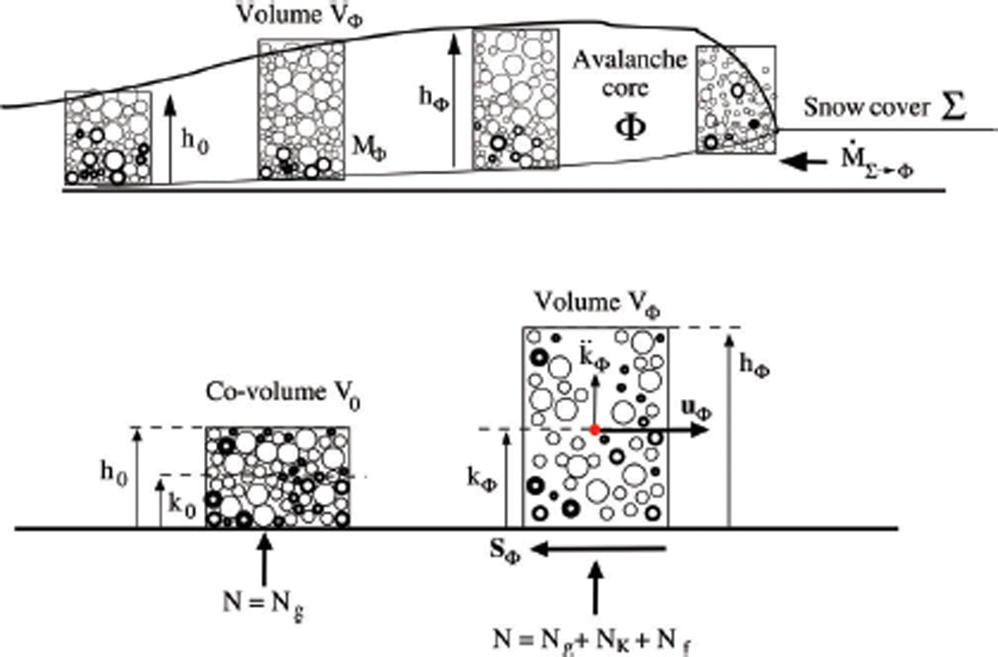
Definition of model parameters. The avalanche core is divided into volumes V Φ (representative volume). A volume is located at a fixed position with a constant basal area. The avalanche flows through the volume. The volume has height h Φ and contains mass M Φ. At rest the massfills the co-volume V 0 with height h 0. The at-rest density of the ensemble is ρ 0; the flowing density is ρ Φ. The centre-of-mass is located at h Φ/2 (homogeneous distribution of mass in the avalanche core). The slope-parallel velocities are denoted u Φ. The kinetic energy of the velocity fluctuations is R K. Granular interactions at the basal boundary induce a dispersive pressure N K and changes in the ensemble configuration and therefore potential energy R V of the granular ensemble.
Avalanche Mass, Volume and Energy
We consider the avalanche core Φ to consist of representative volumes V Φ (Fig. 2). The height of the volume is the avalanche flow height h Φ. The volumes contain particulate snow mass in the form of granules or snow fragments. The amount of mass in the volume is M Φ. As we model the granular ensemble as a continuum, the self-weight of the granules is N g. The interactions between particles can be frictional, typical of dense flows, or collisional, typical of mixed powder snow avalanches. Because the volume contains mass in granular form it can shear and expand under the action of forces. The volume expansion is upwards, because of the free upper surface of the flow and because the granules are hindered by the hard basal boundary. The centre-of-mass of the volume is located at k Φ = h Φ/2, which implies, we assume for now, a homogeneous mass distribution. If the volume was not moving the granules would quickly settle to the co-volume V 0 with height h 0. We specifically employ the terminology ‘co-volume’, as it is commonly used to describe how cohesion and molecules of finite size influence the behaviour of ideal gases (Reference RowlinsonRowlinson, 2002). The density of the co-volume depends on the size and internal arrangement of the granules. We postulate that this density of the co-volume is known, or can be approximated accurately. The flow density ρ Φ is defined by the ratio of the avalanche volume V Φ to the avalanche co-volume V 0:
The snow is moving through the volume parallel to the slope with a mean speed of u
Φ. The location of the centre-of-mass k
Φ can change, either by adding more material to the volume element (mass flux from neighbouring volumes), or because of pressures arising from the interaction of the granules with the basal boundary, which cause the centre-of-mass to move upwards or downwards. We term this additional pressure the dispersive pressure N
K (Reference BagnoldBagnold, 1954), and denote the acceleration of the centre-of-mass associated with the dispersive pressure ![]() . The dispersive pressure can only exist with a corresponding acceleration of the centre-of-mass. The total normal pressure N at the basal surface is therefore given by the sum of the weight N
g and the dispersive pressure N
K:
. The dispersive pressure can only exist with a corresponding acceleration of the centre-of-mass. The total normal pressure N at the basal surface is therefore given by the sum of the weight N
g and the dispersive pressure N
K:
Centripetal pressures N f arising from terrain undulations will also increase or decrease the total pressure N at the avalanche base (Reference Fischer, Kowalski and PudasainiFischer and others, 2012). Because N f is the reaction at the avalanche base from the centrifugal acceleration, it is the centripetal pressure.
Acting against the slope-parallel movement of the representative avalanche volume is the shear, S Φ (Fig. 2), a vector quantity as it acts in the direction opposite to the flow directions, u Φ. The shear stress S Φ depends on the total pressure N as well as on the flow density. To describe the density of the representative volume V Φ we use two mechanical energies: (1) the kinetic energy associated with random particle movements R K (Reference Bartelt, Buser and PlatzerBartelt and others, 2006) and (2) the potential energy associated with the z-location of the centre-of-mass R V (Reference Luca, Fang and HutterLuca and others, 2004; Reference Buser and BarteltBuser and Bartelt, 2011). The kinetic energy R K is calculated from the difference between the individual particle velocities and the mean slope-parallel speed of the avalanche. The potential energy R V is calculated from the position of the individual particles with respect to the co-volume height as the reference. R V describes the flow configuration in the volume. Both R K and R V are connected with the random position of the particles. The sum of R K and R V is denoted the free mechanical energy, R,
The primary role of cohesion is to limit the free mechanical energy in the avalanche. Shearing in the slope-parallel direction S
Φ will produce random particle movements and therefore R
K. However, the random particle movements in the slope-perpendicular direction are inhibited by the basal boundary, and subsequently cause the location k of the centre-of-mass to change. Moreover, shearing of the volume V
Φ produces both kinetic energy at a rate ![]() and volume (density) changes at a rate
and volume (density) changes at a rate ![]() . The sum of
. The sum of ![]() and
and ![]() defines the production of total free energy
defines the production of total free energy ![]() of the volume V
Φ:
of the volume V
Φ:
The partitioning of ![]() is governed by the interaction with the basal boundary, as the kinetic energy of the random particle movements is transformed into potential energy at the boundary. The change in potential energy
is governed by the interaction with the basal boundary, as the kinetic energy of the random particle movements is transformed into potential energy at the boundary. The change in potential energy ![]() with respect to the total
with respect to the total ![]() is the dimensionless quantity γ:
is the dimensionless quantity γ:
Avalanche Model Equations
To model snow avalanche flow we apply the equations developed by Reference Buser and BarteltBuser and Bartelt (2015). This model formulation predicts not only the slope-parallel velocities u Φ of the avalanche in three-dimensional terrain (Fig. 3) but also streamwise density variations ρ Φ in the avalanche core, that are induced by terrain roughness and granular interactions with the basal boundary. As we employ a depth-averaged approach, the model provides no information on the variation of density in the slope-perpendicular direction.
Definition of the model coordinate system. The elevation of the model domain Z is defined in an (X,Y) coordinate system. Gravity is given by the vector g = (gx , gy , gz ). The avalanche flows in the three-dimensional terrain with slope-parallel velocity u Φ. Acting against the flow is the shear stress vector S Φ, which depends on the cohesion N 0.
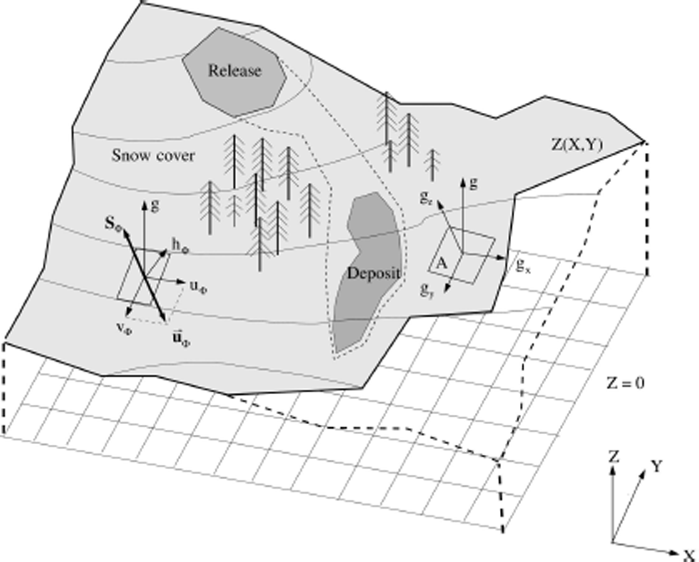
The general system of seven differential equations describes the mass, momentum and energy balances in a representative avalanche volume V Φ (Fig. 2). We consider two masses: the mass of solid particles M Φ and the mass of air in the volume V Φ. Because the density of air is constant we need only consider the height h Φ in the balance equations. We do not consider the self-weight of the air, as it is much smaller than the weight of the avalanche. The mathematical description of mountain terrain is defined using a horizontal (X, Y) coordinate system. The elevation Z(X, Y) is specified for each (X, Y) coordinate pair. We introduce a local surface (x, y, z) coordinate system with the directions x and y parallel to the metric geographic coordinates X and Y. The grid of geographic coordinates defines inclined planes with known orientation; the z-direction is defined perpendicular to the local x-y plane. The equations can be written in vector form as
with the seven unknown state variables
The components of U Φ include the mass M Φ per unit area and the avalanche momentum in the directions parallel to the slope, M Φ u Φ and M Φ v Φ. The velocities u Φ and v Φ are defined in the x- and y-directions, parallel to the avalanche slope (Fig. 3). The remaining state variables are the non-directional kinetic energy associated with granule velocity fluctuations R (Reference Bartelt, Buser and PlatzerBartelt and others, 2006), the flow height of the core, h Φ, the slope-perpendicular momentum M Φ w Φ and the dispersive pressure N K. The derivation of this system of equations is given by Reference Buser and BarteltBuser and Bartelt (2011, Reference Buser and Bartelt2015). The flux components (Φ x , Φ y ) are:

The driving forces G Φ are

The term ![]() represents the snow influx by entrainment (Reference Christen, Kowalski and BarteltChristen and others, 2010). We do not consider the influence of cohesion on entrainment in this paper. The parameters α and β
K control the production of free mechanical energy R (Reference Buser and BarteltBuser and Bartelt, 2009).
represents the snow influx by entrainment (Reference Christen, Kowalski and BarteltChristen and others, 2010). We do not consider the influence of cohesion on entrainment in this paper. The parameters α and β
K control the production of free mechanical energy R (Reference Buser and BarteltBuser and Bartelt, 2009).
The flowing avalanche is driven by gravitational acceleration in the tangential directions G = (Gx
, Gy
) = (M
Φ
gx
, M
Φ
gy
). The acceleration in the slope-perpendicular direction is denoted g′ and is composed of three accelerations, gravity gz
, dispersive acceleration ![]() and centripetal acceleration fz
:
and centripetal acceleration fz
:
These accelerations are associated with normal pressures
The bed normal pressure N = N g + N K + N f assumes that the material is continuous and therefore that the particles are in continual contact. As in all depth-averaged models, the pressure N g is calculated from the total mass of particles in the volume. Snow particles that become detached will lead to smaller pressures N g. However, as we model the flow of particles inside a defined volume, it is possible to define a centre-of-mass and therefore it is not necessary to track individual particle trajectories.
The model assumes that the lateral stresses are equal to the bed normal stress. However, the bed normal stress is no longer hydrostatic and equal to the avalanche weight, N g. The bed normal stress can increase or decrease depending on the dispersive pressure N K. An increase in the bed normal stress is associated with compressive (passive) granular flow states, in which the centre-of-mass of the granular ensemble is increasing; a decrease in the bed normal stress corresponds to extensive (active) flow states, in which the centre-of-mass of the granular ensemble is falling. The model therefore accounts for lateral active/passive flow states by adjusting the height of the flow by the dispersive pressure. Note that this approach differs from any approach that includes lateral stress coefficients (e.g. Reference SalmSalm, 1993; Reference Bartelt, Salm and GruberBartelt and others, 1999; Reference Pudasaini and HutterPudasaini and Hutter, 2007).
Frictional resistance is given by the Voellmy-type shear stress S Φ = (S Φx , S Φy ), with
with
and the speed-dependent part of the friction
We define the functional dependency of the friction parameters (μ, ξ) on the configurational energy R V as
and
With this frictional model μ
0 and ξ
0 are the static friction coefficients associated with non-fluidized flowing snow, R = 0. The model parameter R
0 defines the activation energy required to fluidize the core (Reference Bartelt, Bühler, Buser, Christen and MeierBartelt and others, 2012a). As we shall see, the activation energy increases with the cohesive bonding of the granules. Free mechanical energy is produced from the shear work rate in the slope-parallel (xy) flow direction ![]() (see Reference Bartelt, Buser and PlatzerBartelt and others, 2006; Reference Buser and BarteltBuser and Bartelt, 2015):
(see Reference Bartelt, Buser and PlatzerBartelt and others, 2006; Reference Buser and BarteltBuser and Bartelt, 2015):
where the total frictional work rate is
The dissipation of energy in the z-direction is defined by the work rate ![]() . The model parameter α describes the production rate of random energy from the shear work
. The model parameter α describes the production rate of random energy from the shear work ![]() in the slope-parallel direction
in the slope-parallel direction
Because the snow granules are inelastic, granular interactions will cause the fluctuation energy to decay to heat at a rate β
K (Reference Buser and BarteltBuser and Bartelt, 2009). All free energy must decay eventually to internal energy E; all work that does not produce random energy is dissipated immediately to heat at a rate ![]() . Therefore,
. Therefore,
The system of governing differential equations is energy-conserving (Reference Bartelt, Buser and PlatzerBartelt and others, 2006; Reference Buser and BarteltBuser and Bartelt, 2015) since balance equations are written for the free mechanical energy,
and therefore
This fulfils the requirement that the sum of the changes in kinetic energy ![]() , the change in random kinetic energy
, the change in random kinetic energy ![]() and change in heat energy
and change in heat energy ![]() (dissipation) is equal to the work done by gravity
(dissipation) is equal to the work done by gravity ![]() :
:
We apply second-order HLLE schemes (Reference Harten, Lax and Van LeerHarten and others, 1983) to solve Eqn (6) on general quadrilateral grids (Reference Christen, Kowalski and BarteltChristen and others, 2010). Cohesion modifies the shear S Φ, the expansion of the flow volume and the activation energy R 0. Each will be discussed in the following sections.
Cohesion N 0 and shear stress S
Cohesion operates on both the directional kinetic energy and on the non-directional free energy of the avalanche. The effect of cohesion on the directional kinetic energy, i.e. the mean slope-parallel velocity, is introduced by modifying the shear stress S. In depth-averaged models, the shear stress S represents the total resistance to the driving force of gravity. Because we model avalanche flow from initiation to deposition, the shear stress function must be able to model conditions of static equilibrium and zero avalanche velocity. In this case, the total shear force is in balance with the total driving force acting on the avalanche. The shear is the reaction to the driving force. The direction of the shear stress is therefore always defined in the direction opposite to the direction of the slope-parallel flow, given by the avalanche velocity components (see Eqn (12)). Although cohesion is a non-directional force, in the sense that all bonds are randomly distributed, the direction of the shear gives the cohesion a directional character.
Shear S and normal N stresses of flowing snow have been measured at the Weissfluhjoch (Davos experimental chute; Fig. 4a). The measurement plate is embedded in the basal surface of the chute and measures the shear and normal reactions. Therefore N is positive upwards and S is positive when it acts against the flow. The normal pressure N is the total pressure and consists of the self-weight N g, the dispersive pressure N K and the centripetal pressures N f (Eqn (2)). The total pressure can be negative, zero or positive. In case of negative N the avalanche has no contact with the basal surface and the shear stress is zero, S = 0. Reference Platzer, Bartelt and KernPlatzer and others (2007a,Reference Platzer, Bartelt and Jaedickeb) provide further details of the experiments.
Snow-chute experiments. (a) The snow chute located at the Weissfluhjoch, Switzerland. (b) Measured shear S and normal N stress for experiment 4 with Eqn (29) fit. (c) Measured shear S and normal N stress for experiment 9 with Eqn (29) fit. Note the hysteresis of experiment 4. Reference Platzer, Bartelt and KernPlatzer and others (2007a,Reference Platzer, Bartelt and Jaedickeb) provide further details of the experiments.

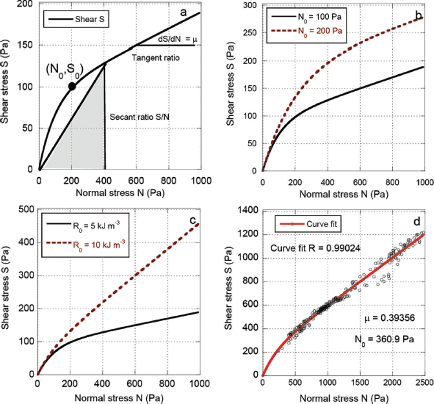
The experiments with both dry and wet snow exhibit a nearly linear relationship between S and N (Fig. 4b and c). This suggests that a function of the form
would be appropriate to model the experimental results. The coefficient c is defined by the y-intercept in the N-S plane and is typically denoted as the cohesion or yield stress (Reference MitchellMitchell, 1993), i.e. the shear stress independent of the normal stress N.
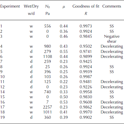
Although it would be possible to fit the experimental results with Eqn (25), we adopted an alternative approach, based on both theoretical considerations and the experimental results. Firstly, Eqn (25) does not have the property that S = 0 for N = 0. This point is a theoretical constraint for the shear resistance. It is trivially satisfied when using the standard Voellmy model. Because the shear stress is the total resistance (reaction) at the measurement plate, the shear stress must go to zero (S → 0) as the mass decreases (N g → 0). In the limit, there can be no shear stress when there is no mass. Equation (25) does not reproduce this behaviour and confuses internal molecular bonding with the shearing induced by external forces. For the sake of simplicity, these theoretical considerations could be readily ignored. However, a decrease in shear S at small N was observed in several of the experiments (e.g. experiment 9, Fig. 4c; experiment 19, Fig. 5d). Interestingly, this effect was most noticeable in the experiments in which the S–N plot did not exhibit a strong hysteresis. The avalanche front and tail have different values of μ (Reference Platzer, Bartelt and KernPlatzer and others, 2007a,Reference Platzer, Bartelt and Jaedickeb), indicating different flow configurations (R V) for the same normal pressure. Hysteresis therefore suggests the presence of large dispersive pressures that are needed to change the avalanche flow configuration. To model the effect of the observed hysteresis, we impose the condition that dS/dN = μ(R V) at the limit N → ∞ (Fig. 5). This constraint on the shear function allows us to model the hysteresis and the highly variable slope of the shear response (Fig. 5; Table 1).

Summary of snow-chute experiments. Values of N 0, μ and goodness of fit with Eqn (29). Note the strong variation in both N 0 and μ. The dry flows had a mean N 0 ≈ 2000 Pa; the cohesion of the wet flows varied considerably, often exhibiting very high values, N 0 ≈ 1000 Pa. In many of the wet snow experiments the location of the transition, N 0, could not be determined because of the high friction coefficients, μ. SS denotes that the avalanche reached steady-state flow
In summary, to reproduce the observed behaviour we fit the experimental results with a function that satisfies the following conditions:
and
The last condition, Eqn (28), requires that when the flow height is small (near zero), the shear and normal stress increase in equal proportion (dS/dN = 1). This condition facilitates a smooth but sharp transition between the two theoretical limits. Although the slope could take other values, we set dS/dN = 1 to avoid the definition of an additional free parameter. It ensures the steepest possible increase in shear for small normal pressures.
A function that satisfies these conditions is
where depends on the flow state μ(R V). N 0 is a fit parameter defining the location of the inflection point of the shear curve (Fig. 5b). Fitted values of N 0 for 18 chute experiments with dry and wet snow are presented in Table 1. When N 0 = 0 (no cohesion), Eqn (29) reduces to the Coulomb friction model, S = μ(R V)N. When N 0 > 0, the shear stress is increased, accounting for the increase in shear stress observed in the experiments (that cannot be modelled with the standard Coulomb friction model). For large values of N the slope of the function is dS/dN = μ(R V). Thus, the function Eqn (29) runs parallel to the standard Coulomb model (c = 0), as observed in the measurements. For small values of N the slope of the function is dS/dN > μ(R V), modelling the transition from a static coefficient of friction to a dynamic coefficient of friction. The use of dS/dN = 1 at N = 0 fits the results well. Another feature of Eqn (29) is that the total normal pressure, N, is used (Reference Rainer and FellinRainer and Fellin, 2006). Because N consists of the dispersive pressure N K and centripetal pressures N f the effect of random fluctuations and track curvature are taken into account. The assumption of an exponential decay of the basal friction angle is in agreement with the interface behaviour of cohesionless soils (Reference PotyondyPotyondy, 1961; Reference Tejchman and WuTejchman and Wu, 1995).
The function has two characteristics that are important for practical applications: (1) N 0 assumes values that are comparable to measured values of cohesion (Reference Voytkovskiy and BarteltVoytkovskiy, 1977) and (2) when N 0 = 0, the standard Coulomb model (c = 0) is recovered. One assumption of Eqn (29) is that the effect of cohesion is predominant in the Coulomb friction term. The experiments were performed at low velocity, when turbulent effects are negligible. Thus, when fitting the chute experiments, we did not consider the velocity-squared-dependent friction (ξ) because the velocities in the experiments are small. Shear stresses from the velocity-dependent friction are <50 Pa for the highest velocities in the experiments.
Activation Energy
The chute experiments reveal a large variation in friction μ (Table 1). The largest measured value of μ is 0.55 while the smallest measured value is 0.22. The variations cannot be due to the surface properties of the chute, because the surface of the chute remained the same during the experiments. The variations are large even within the two general sub-categories wet and dry. To model the change in
Coulomb friction μ we employ the relation
We therefore make the friction a function of the potential (configurational) energy R V (Reference Bartelt, Bühler, Buser, Christen and MeierBartelt and others, 2012a). The activation energy R 0 scales the potential energy R V and controls the change in friction with respect to the change in flow configuration. It is related to the potential energy needed to expand the volume of the core in order to ‘activate’ or allow movement. More energy is needed to activate flows with large overburden pressures (large flow heights). The parameter μ 0 defines the friction μ when R V = 0, and can be considered to be the maximum friction of the co-volume V 0 (or height, h 0) as the avalanche is flowing in its most dense possible state where the friction is the highest. Moreover, μ 0 can be considered the static coefficient of friction, because R V = 0 when the flow is at rest. From the experiments, we take the maximum μ 0 = 0.55. The activation energy can be expressed as an energy density (J m−3) or stress (N m−2).
Cohesive interactions between snow granules introduce a binding potential that must be overcome to decrease the value of friction μ. We account for this cohesive binding by increasing the activation energy R 0 (which is associated with gravitational potential) by the value N 0 (which is associated with cohesive potential). Equation (30) then becomes
Thus, more energy (R V) is required to decrease the friction for higher N 0 values. Alternatively, for cohesionless flows, μ can decrease significantly, with little change in the configurational energy. In general, cohesive flows will have higher μ values than non-cohesive flows, as more energy (R V) is required to alter the flow configuration. However, it is quite possible that cohesive flows have small Coulomb friction values, depending on the energy R V. This result is in accordance with the experiments, which reveal that flows with high cohesion values N 0 can exhibit small μ values.
Volume Expansion
Cohesive bonding between snow granules hinders the expansion of the avalanche core Φ. Cohesion reduces the free mechanical energy in the avalanche and, therefore, avalanche flows with cohesion are less disperse and exhibit higher bulk flow densities. Random particle motions (R K) can co-exist with cohesive granular interactions; but the lifetime of the random energy is smaller. Because the avalanche core cannot easily expand, active (extensive, low density) flow states are hindered. Lateral stresses remain high. Dense avalanche flows result as more energy is required to break the cohesive bonds between snow granules. Thus, cohesion operates on the non-directional, random free energy in the avalanche core. It is this effect that is seldom included in avalanche dynamics models. Modelling the effect of cohesion on the free mechanical energy of the avalanche therefore facilitates a better description of different avalanche flow regimes, including active and passive flow states.
We model the volume expansion by treating the cohesion N 0 as an additional pressure that must be overcome in order to expand and deform the granular ensemble in the slope-perpendicular direction. The approach concentrates all stress into the slope-perpendicular movement of the centre-of-mass. This idea is congruent with Van der Waals modification of the ideal gas law to include cohesive molecular interactions in a representative volume (Reference RowlinsonRowlinson, 2002).
Let the work done to expand the core volume V Φ be defined by the total pressure N working at the base of the avalanche
where M
Φ is the mass of granules in volume V
Φ and N
g is the perpendicular component of the self-weight. The slope-perpendicular acceleration of the centre-of-mass ![]() (Fig. 2) is induced by the dispersive pressure N
K, which arises from the granular interactions with the running surface
(Fig. 2) is induced by the dispersive pressure N
K, which arises from the granular interactions with the running surface
For the moment we consider no mass transport from neighbouring volumes. Changes in position of snow granules within the avalanche core are therefore associated with changes in the mean potential energy of the granular ensemble, which is described by the location of the centre-of-mass k
Φ. The total work done per unit time by the normal pressure at the bottom of the avalanche, N, which includes the weight N
g and the dispersive pressure N
K, must be in balance with the total working of the granular interactions per unit volume at the boundary. We have termed this energy the free potential energy production ![]() . Therefore,
. Therefore,
and, with ![]() ,
,
The ratio ![]() physically represents the upward expansion of the avalanche in the z-direction, expressed as a strain rate
physically represents the upward expansion of the avalanche in the z-direction, expressed as a strain rate ![]() :
:
Therefore,
With cohesion, N 0, these relations are modified slightly. The total pressure, N, needed to deform the volume is now
as we treat the cohesion as an additional pressure that must be overcome to change the location of the centre-of-mass of the granular ensemble:
The model assumes that the strain rate is constant over the entire flow height of the volume. Therefore, the effect of cohesion is not restricted to the basal boundary. Equation (39) can be written as a third-order differential equation in k Φ,
or, more conveniently as a series of three first-order equations in terms of the centre-of-mass height k Φ, velocity
w Φ and dispersive pressure N K:
Equation (43) includes N 0 and replaces the last line in Eqn (9). In numerical solutions we consider control volumes that are fixed in space and therefore must account for the convective transport of k Φ, w Φ and N K. Hence, the use of the substantial derivative operator in Eqns (41–43). The equations account for the change in potential energy and slope-perpendicular acceleration due to mass flow from neighbouring volumes (Reference Buser and BarteltBuser and Bartelt, 2015).
Example calculations
Snow-chute experiments
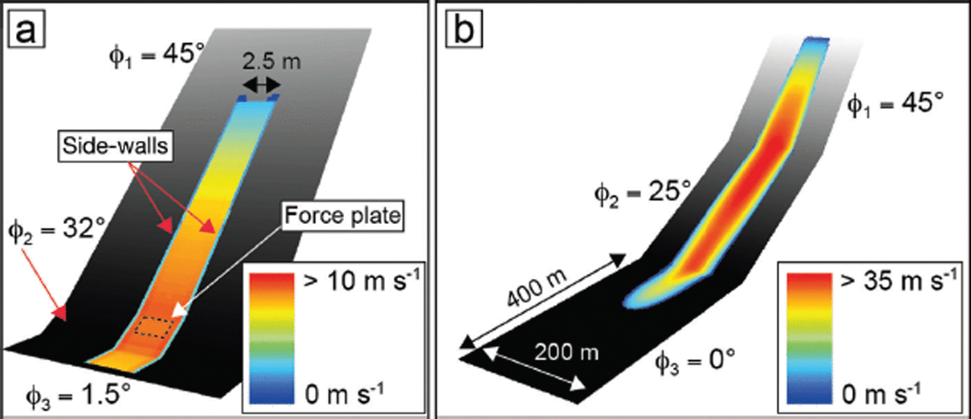
As a first example we simulate the snow-chute experiments of Reference Platzer, Bartelt and KernPlatzer and others (2007a,Reference Platzer, Bartelt and Jaedickeb). The model of the snow chute is depicted in Figure 6. The chute contains a 10 m long acceleration zone with inclination 45°, a short 32° transition zone and a flat 2.15 m long measurement section. Snow is released by opening the gate to a 10 m long hopper located above the acceleration zone. Starting volumes are V 0 < 25 m3. The flow mass typically runs past the measurement section and does not accumulate. Flow is constrained by side-walls that are spaced 2.5 m apart. Shear and normal force plates are installed in the transition zone.
Model domains for (a) snow chute and (b) idealized avalanche slope. The snow chute consists of three planar segments: l 1 = 20 m, φ 1 = 45°, l 2 = 1.6m, φ 2 = 32°, l 3 = 2.15m, φ 3 = 1.5°. No flux boundary conditions are used to constrain the flow within the chute side-walls. The width of the chute is 2.5 m. The idealized avalanche slope also consists of three track segments: l 1 = 200 m, φ 1 = 45°, l 2 = 300m, φ 2 = 25°, l3 = 400m, φ 3 = 0°. The idealized slope is not channelled and the avalanche can spread laterally.
The cohesion model we propose is designed for fully granularized avalanche flows. It does not take into account the process of snow-cover fragmentation. The model is only valid after the slab has displaced several metres. In most applications this is the case, as the running distance is considerably larger than the granularization distance, even when considering the motion of small avalanches with volumes V 0 ≈ 100 m3. In the snow-chute experiments the snow placed in the release hopper at first displaces as a rigid block of snow, before roughness elements installed on the basal surface cause fluidization. To handle this problem we place the starting mass 5 m downstream of the hopper for the calculations. At this point the mass is given an initial velocity (2.5 m s−1) corresponding to the drop height and the slope angle.
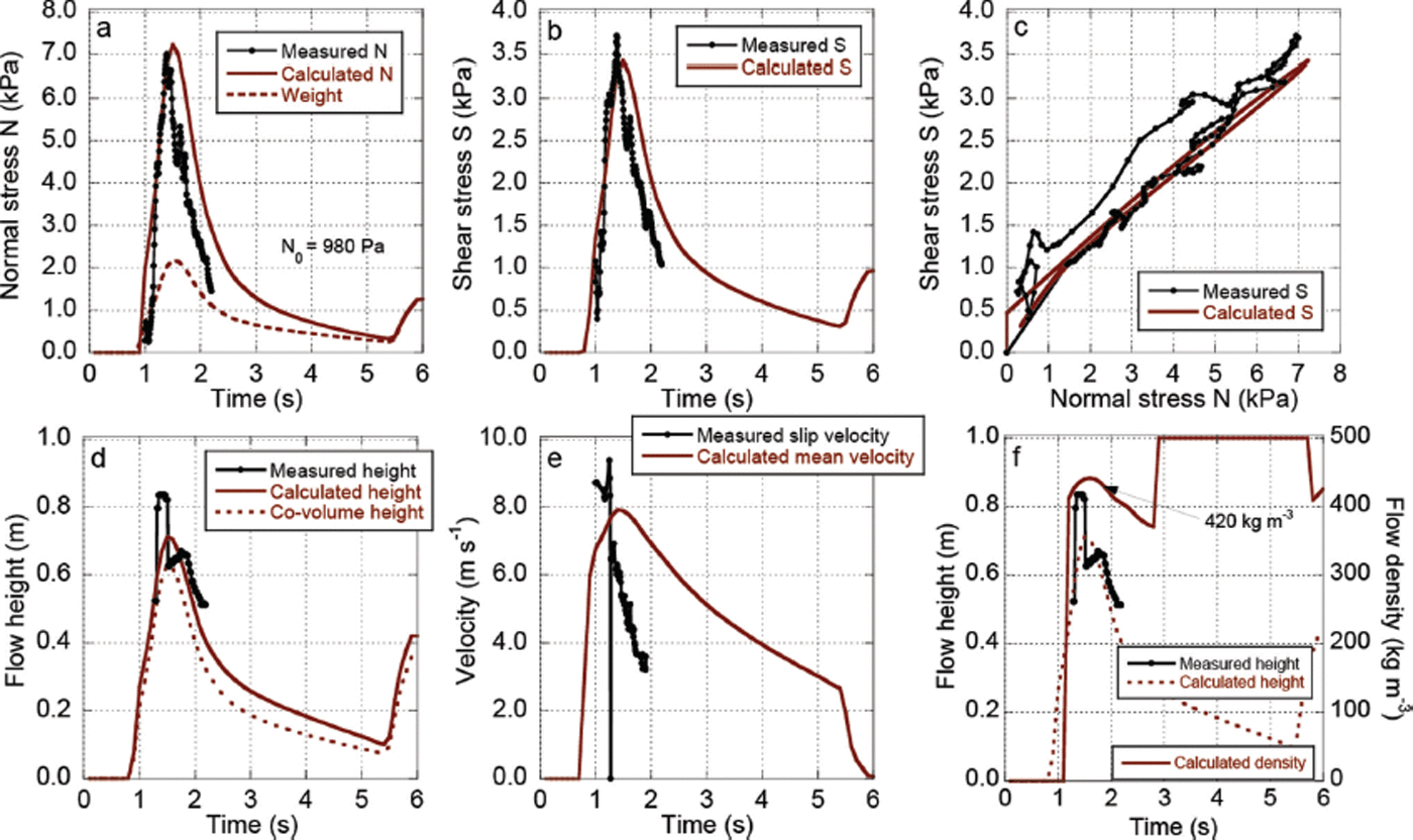
A wet (No. 4) and a dry (No. 9) snow experiment (Table 1) were simulated with the cohesion model. The values of cohesion N 0 found from the experiments were used in the simulations, N 0 = 980 and 396 Pa for experiments 4 and 9, respectively. In both cases it was possible to reproduce the measured normal pressure (Figs 7a and 8a). This requires modelling the centripetal accelerations of the flow at the slope deviation. The centripetal pressures are approximately twice as large as the self-weight. The time duration of the normal load over the force plate appears to be modelled correctly, indicating that the calculated mean velocity of the flow is correct. The shear response is correctly represented in both cases (Figs 7b and 8b), providing an accurate representation of the measured S–N relationship (Figs 7c and 8c). In the dry experiment it was possible to model the shear hysteresis existing between the front and tail of the flow (Fig. 8c). Avalanches exhibit different shear values for the same normal pressure because of differences in velocity and free-energy content. The shear stress at the tail of the wet flow is slightly underestimated (Fig. 7c). The slope of the modelled S–N relationships is correct, giving good agreement with the measured values (Table 1). The maximum flow heights are well represented, although the simulations show longer, less finite-type tails (Fig. 8d). The calculated height values at the tail are near the dimension of a single granule. A direct comparison between measured and calculated velocities is not possible, because only the basal slip velocities were measured, using upward-looking optical sensors (Fig. 8e). The model provides only the mean velocities, which should be larger than the measured basal slip velocities. Note that the velocities are required to predict the centripetal accelerations and the agreement between the measured and calculated normal stresses implies a good agreement with the mean velocity. The difference between the slip and mean velocities implies large velocity gradients in the flow body. The calculated densities are reasonable (Figs 7f and 8f), but without experimental verification. The model predicts that both the extreme front and tail of the flow have lower densities than the flow bulk. The co-volume density of wet snow was taken to be ρ 0 = 500kgm−3 and that for dry snow to be ρ 0 = 400 kg m−3. We assume lower-density granules for the dry snow flows, in agreement with the density measurements made before the experiments (Reference Platzer, Bartelt and KernPlatzer and others, 2007a,Reference Platzer, Bartelt and Jaedickeb).
Measured and calculated shear and normal stresses for wet snow-chute experiment 4 (Table 1). Measured and calculated N 0 = 980Pa. (a) Normal stress N. The normal stress consists of the weight, centripetal and dispersive pressures. (b) Shear stress S. (c) Relationship between S and N. (d) Flow heights, including calculated co-volume height h 0. (e) Measured slip velocity and calculated mean velocity of flow. (f) Calculated density. The bulk density ρ Φ ≈ 420 kg m−3. Flow parameters: μ 0 = 0.55; ξ 0 = 2000ms−2; α = 0.07; β = 0.80 s−1; γ = 0.20; R 0 = 0.50 kJ m−3.
Measured and calculated shear and normal stresses for dry snow-chute experiment 9 (Table 1). Measured and calculated N 0 = 396Pa. (a) Normal stress N. The normal stress consists of the weight, centripetal and dispersive pressures. (b) Shear stress S. (c) Relationship between S and N. (d) Flow heights, including calculated co-volume height h 0. (e) Measured slip velocity and calculated mean velocity of flow. (f) Calculated density. The bulk density ρ Φ ≈ 340 kg m−3. Flow parameters: μ 0 = 0.55; ξ 0 = 2000ms−2; α = 0.10; β = 0.80 s1; γ = 0.20; R 0 = 0.50 kJ m−3.

Idealized avalanche slope
The snow chute does not contain a runout zone and is limited to small flow volumes of <10 m3. To demonstrate the effect of cohesion on avalanche runout, flow density and velocity, we replaced the experimental chute with an idealized avalanche domain consisting of three planar slope segments (Fig. 6b). The lengths l and inclination angles of the planar segments are l 1 = 200 m, φ 1 = 45°, l 2 = 300m, φ 2 = 25°, l3 = 400m, φ 3 = 0°. Thus the slope contains a steep starting zone, followed by a long transition zone (similar in dimension to the Vallée de la Sionne transition zone) and a flat runout zone. A snow volume of V 0 = 2350 m3 with density ρ 0 = 200kgm−3 was released from the steep track segment. We assume that the avalanche is granularized immediately at release. The avalanche entrained h Σ = 0.25 m of snow with density ρ Σ= 150 kg m−3. All model parameters remained the same, except for the value of the cohesion: N 0 = 0, 100, 200, 500, 1000, 2000 Pa. Thus, six simulations were performed with cohesion values within the range of the measured cohesion values of the snow-chute experiments (Table 1). Calculated runout distances (Fig. 9), maximum calculated velocities (Fig. 10), shear and normal stress response (Fig. 11) and flow density (Fig. 12) are reported. In all simulations the parameters μ 0 = 0.55, ξ 0 = 2000ms−2, α = 0.1, β K = 0.80 s−1, R 0 = 2 kJ m−3 are used. These values provide the best agreement with measured runout and velocity of mixed dry snow avalanches captured at the Vallée de la Sionne test site (Reference Bartelt, Bühler, Buser, Christen and MeierBartelt and others, 2012a; Reference Buser and BarteltBuser and Bartelt, 2015).
Calculated runout and maximum velocity for six model calculations with (a) N 0 = 0 Pa, (b) N 0 = 100 Pa, (c) N 0 = 200 Pa, (d) N 0 = 500 Pa, (e) N 0 = 1000 Pa, (f) N 0 = 2000 Pa. The larger the cohesion the shorter the runout.

Comparison of maximum calculated velocity for five cohesion values on idealized avalanche slope (N 0 = 0, 100, 500, 1000, 2000 Pa). The higher the cohesion the lower the avalanche velocity.

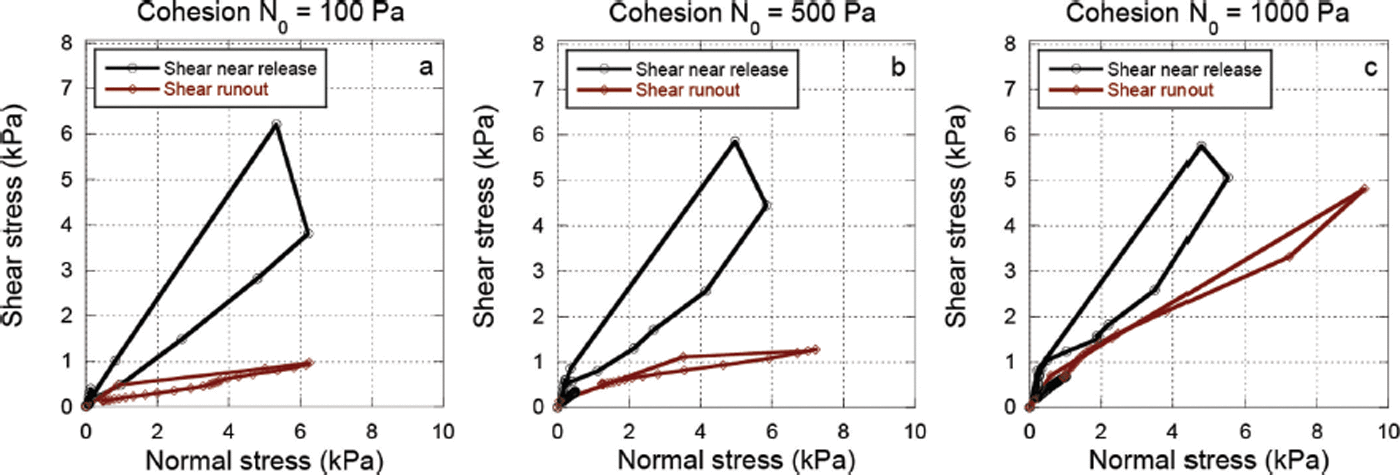
Calculated shear stress for three cohesion values (a) N 0 = 100 Pa, (b) N 0 = 500 Pa, (c) N 0 = 1000 Pa. The black curves depict the shear stress in the upper track segment immediately after avalanche release. The shear stress exhibits a strong hysteresis. The red curves depict the shear stress in the lower track segments. Note the strong similarity to the chute measurements.
Calculated flow density ρ Φ and core height h Φ in the transition zone for two cohesion values, N 0 = 0 and 1000 Pa. The avalanche with N 0 = 0 reaches the transition zone first, at t ≈ 15 s. The core height at the avalanche front is high, >3m. The avalanche with N 0 =1000 Pa reaches the transition zone after t ≈ 20 s in two surges, a low-density first surge and a high-density second surge. The avalanche is longer. Surge-like behaviour was often observed with high cohesion values.

Cohesion N 0 has a strong influence on avalanche runout, as shown in Figure 9. The higher the cohesion value, the shorter the runout distance and smaller the avalanche velocity (Fig. 10). For N 0 = 0 Pa, the calculated avalanche runs the full distance of the runout zone (Fig. 9a), while for a value of N 0 = 1000Pa, the calculated avalanche stops shortly after the transition zone, a reduction of ∼400 m in runout distance (Fig. 9e). For large cohesion values, N 0 = 2000Pa, the avalanche stops in the transition zone, almost immediately after release (Fig. 9f). Calculations with high cohesion values also exhibit less lateral spreading. The simulations also reveal that for modest values of cohesion, 0 ≤ N 0 ≤ 500 Pa, it is possible to attain constant velocities in the transition zone (Fig. 10). However, the magnitude of the constant velocity decreases with increasing cohesion, indicating that avalanche velocity is now controlled by both ξ 0 and N 0. Of significance is the fact that all other parameters remained constant and runout was controlled by a single model parameter, N 0. A feature of the model is that extreme runout is defined by the cohesionless case N 0 = 0 Pa.
Shear and normal stresses were calculated in the release and runout zones for different N 0 values (Fig. 11). These S–N relationships exhibit many features common to the experimental snow-chute results, including a shear hysteresis that is especially dominant in the release zone. This indicates that the front and tail of the avalanche experience large differences in shearing as the avalanche accelerates, the front experiencing lower shear resistance. In the runout zone, the hysteresis disappears and the S–N relationships exhibit near-constant slopes. Again, this result is similar to the experimental chute results, where the measured S–N relationship is linear. For N 0 = 100 Pa, the slope dS/dN ≈ 1/6, while for N 0 = 1000 Pa, dS/dN ≈ 1 = 2, indicating a much higher deceleration in the runout zone for higher cohesion values. Again, we emphasize that these results were not obtained by changing μ, but by changing the cohesion.
We also calculated the flow height h and the flow density at a point located in the middle of the transition zone for two different cohesion values, N 0 = 0 and 1000 Pa (Fig. 12). A large difference exists in the calculated flow heights. For the cohesionless case, N 0 = 0 Pa, the highest flow heights and lowest densities are located at the avalanche head. The model predicts that avalanches with cohesionless (dry) snow will have a different front dynamic, exhibiting strong slope-perpendicular accelerations, resulting in higher flow heights and lower flow densities. To model the formation of powder clouds it is necessary to have low granular cohesion (say N 0 ≤ 200 Pa). Behind the head, flow heights decrease and the densities increase to ρ Φ = 230 kg m−3. For higher cohesion values N 0 = 1000 Pa, the flow reaches the observation point in two distinct surges. The second surge has the highest flow height and larger flow density, ρ Φ ≈ 300 kg m−3. The avalanche with the higher cohesion deposits a thin layer of granules at the avalanche tail. These results indicate that cohesion has an influence on the streamwise configuration (density, flow height and velocity) of the avalanche.
Snow avalanche near Verbier, Switzerland
An avalanche that occurred on Mont Rogneux (2600 m), near Verbier, Switzerland, provides an opportunity to demonstrate the role of cohesion in a real case study (Fig. 13). A moist/wet snow avalanche released spontaneously at 17:00 on 13 March 2014, after a day of warm (>0°C) air temperatures. Because of clear weather the location and size of the starting zone could be documented with aerial photographs (Fig. 13a). The avalanche did no damage, but 2m high deposits blocked an access road leading to several buildings (Fig. 13b). Handheld differential global navigation satellite system (dGNSS) measurements were made in the deposition zone (accuracy 10 cm). The avalanche released, accelerated and stopped, essentially on a constant slope (mean slope angle φ = 30°). In places it entrained the entire snow cover, exposing the grassy slope. At slightly flatter track sections, snow was deposited. Such avalanche events cannot be simulated with standard Voellmy-type models (N 0 = 0, α = 0) because they require ad hoc manipulations of the friction parameters (μ 0, ξ 0) to reproduce the observed runout distance, especially on tracks with constant slope.
Runout and starting zone of a wet snow avalanche that released above Verbier, Switzerland, from Mont Rogneux at 17:00 on 13 March 2014. Air temperatures were >0°C. The mean fracture height was h ≈ 1.2 m and the starting volume V 0 ≈ 15000 m3. dGNSS measurements were made on 18 March 2014 in the runout zone.

In the snow-chute experiments (Table 1) moist/wet snow has cohesion values N 0 ≈ 1000 Pa with μ > 0.40 (experiments 4, 6, 18). Higher (N 0 ≈ 2000 Pa, experiment 17) and lower values (N 0 ≈ 500 Pa, experiments 1, 14) are possible. Many of the wet snow experiments have N 0 ≈ 0, but these are accompanied by high values. The cohesion function requires a break in the S–N response to identify the transition point from which N 0 can be determined. The high values of μ found in the experiments indicate that μ 0 > 0.40, as μ 0 represents the highest friction associated with the movement of the co-volume. Therefore, in a first series of numerical experiments with the cohesion model, we took N 0 = 1000 Pa and μ 0 = 0.50 to model moist/wet snow. The remaining parameters were taken from wet snow Vallée de la Sionne experiments (ξ 0 = 1500 m s−2, R 0 = 2.0 kJ m−3, α = 0.05 and β = 1.00 s−1). These values provide acceptable results with respect to avalanche runout and velocity. However, deposition began too early and considerable amounts of snow were deposited in the acceleration zone, leading to deposition heights that were too small at the road. We subsequently lowered the cohesion value to N 0 = 700 Pa (similar to experiment 14). This parameter combination provided the best fit to the observed runout and measured deposition heights (Figs 14 and 15). Deposition heights were calculated at the transects depicted in Figure 14a, where dGNSS measurements were made. Simulations with the standard Voellmy model using guideline values for wet snow avalanches (μ 0 = 0.35) result in avalanches that run too far (Fig. 16). Interestingly, calculated maximum velocities are similar in the transition zone; however, the cohesion model predicts the avalanche stops, while the Voellmy model predicts the avalanche propagates another 400 m with a velocity of 10 m s−1. Calculated depositions in the Voellmy model are concentrated at the avalanche front. The cohesion model predicts not only the lobe structure of the avalanche deposits, but also the location where the two flow arms merged, producing the region of the largest depositions at the north transect. The distance between the cowshed (Fig. 13c) and the location of the smaller flow arm is reproduced. In general the cohesion model leads to less lateral spreading.
Calculated maximum velocities of the Verbier avalanche. (a) Cohesion model with N 0 = 700 Pa. Runout distances and lobe-like deposition features of the actual avalanche are reproduced. The calculated avalanche reached peak velocities of 25 m s1, with the lowest flow densities of ρ Φ = 350 kg m3 at the avalanche front. (b) Voellmy model using guideline value of μ = 0.35 for wet avalanches. Runout distances are too far.

Comparison between measured and calculated deposition heights in the runout zone, Verbier avalanche. The locations of the measurement profiles are depicted in Figure 14a. (a) Lateral cross section. (b) Profile north. (c) Profile south. A co-volume density ρ 0 = 450kgm−3 was used in the calculations.

Comparison between calculated maximum velocities with (N 0 = 700 Pa) and without (Voellmy, N 0 = 0 Pa) cohesion. The calculated velocities are similar, but the cohesion model decelerates the flow in the runout zone, stopping at the road.

A comparison between the Voellmy simulations (N 0 = 0 Pa, α = 0) and cohesion model simulations (N 0 = 700 Pa, α = 0.05) reveals a strong difference in the streamwise character of the avalanche core. Both models result in similar flow velocities at the avalanche front (Fig. 17a), but the cohesion model predicts dense, compact, flow bodies (Fig. 17b), similar to the results found in the snow-chute experiments. The Voellmy model predicts a slow decrease in velocity at the avalanche tail. The calculated S–N relationships are similar (Fig. 17c). However, the cohesion model predicts lower shear stresses for equal normal stresses, because of the decrease of μ < μ 0 in the transition zone.
Comparison between Voellmy model and cohesion model at the point of maximum flow velocity in the acceleration zone. (a) Velocity. (b) Flow height. (c) Calculated S–N relation.

Conclusions
Friction parameters for flowing snow are notoriously difficult to measure in experiments. In the chute experiments of Reference Platzer, Bartelt and KernPlatzer and others (2007a,Reference Platzer, Bartelt and Jaedickeb), Coulomb friction values showed consistent, but wide-ranging values, suggesting that avalanche friction is not governed by constants, but best described as a frictional process. The avalanche community has traditionally relied on avalanche back-calculations to determine parameter ranges and ‘best-fits’ to field observations. This method has the disadvantage that frictional parameters are too strongly linked to a model ansatz or even the numerical implementation of a particular constitutive law. It strongly limits the application of avalanche dynamics models in many practical situations, because the parameters have little or no physical foundation.
To overcome this problem, we began with a set of force plate measurements and sought a frictional process that is missing in the Coulomb part of the Voellmy model. Our goal was to treat avalanche friction as a physical process governed by material constants. The experiments showed that the shear stress versus normal stress response of flowing snow exhibits cohesion, represented by an increase in shear stress S for a given normal pressure N. For small flow heights (low overburden pressures), the slope of the shear response is higher than predicted by the standard Coulomb friction law, S = μN. We attribute this effect to the cohesive bonding between flowing snow granules. To fit the experimental results in this region, an equation was found that fulfils the conditions: S = 0 for N = 0; dS/dN = 1 for N = 0. For large flow heights the relationship between shear and normal force is linear, but the slope varies, 0.22 < dS/dN < 0.55. This strong variation in slope (friction, μ) we attribute to frictional processes involving the free mechanical energy in the core of the avalanche. We postulate that (1) cohesive bonding between the snow granules decreases the free-energy content of the avalanche core and (2) cohesive bonding between snow granules increases the activation energy required to fluidize the core. Cohesive avalanche flows therefore have higher flow densities and larger friction (μ) values. In the model all three effects are controlled by a single parameter, N 0.
A common criticism of process-based avalanche dynamics models is the increase in the number of parameters needed to describe the process physics. In this particular model, parameters are required to define the production and decay of free mechanical energy that is associated with random particle movements and positions. Breaking and creating cohesive bonds in the avalanche core is also a random process, similar to the production and decay of the free energy. Cohesion is therefore a part of the randomness in the flowing avalanche core. Bonds are created and broken in all directions. We simulate this process with only one parameter: N 0. It is our goal to replace the myriad of (μ, ξ) pairs needed to simulate avalanches with a constant set of six parameters (μ 0, ξ 0, N 0, α, β, γ). Our task is to replace the multitude (and many ambiguities) of and of the well-established Voellmy model with material constants and process physics. This cannot be done without parameterizing the random state of the flowing avalanche core. This includes cohesion.
We do not exclude the possibility that the avalanche cohesion N 0 will change from initiation to runout, especially in long-running avalanches that significantly change their temperature, due to frictional heating or entrainment of warm, moist snow. In real avalanches values of N 0 may vary significantly. The evolution of the avalanche flow, often determined by boundary conditions, such as terrain features and entrainment processes, then becomes important to predict avalanche runout. It is also not clear that a single N 0 value represents cohesion in the avalanche body and at the basal interface. In the present work cohesion is a model fit parameter that needs more detailed experimental study. How cohesion N 0 varies as a function of snow temperature and moisture content will soon be determined in sets of independent measurements using existing experimental facilities and equipment.