

Introduction
The response of glaciers in the Southern Alps of New Zealand to global climate change is of interest as records of glacier behaviour in the Southern Hemisphere remain quite rare. The Southern Alps are surrounded by ocean, and their mid- latitude location means they are strongly influenced by both subtropical and polar air masses. The interaction of these contrasting air masses within the prevailing westerly airflow leads to synoptic-scale atmospheric circulation having a large control on glacier behaviour (Reference Fitzharris, Hay and JonesFitzharris and others, 1992, Reference Fitzharris, Chinn and Lamont1997; Reference Clare, Fitzharris, Chinn and SalingerClare and others, 2002; Reference Gillett and CullenGillett and Cullen, 2011). The relative strength of the prevailing westerlies is critical to glacier advance or positive mass balance, as the 600 km long, 2–3 km high barrier that the Southern Alps pose to the westerly airflow leads to significant orographic precipitation, with rates likely to be >12 m w.e. a−1 in the highest-elevation areas immediately west of the main divide (Reference Griffiths and McSaveneyGriffiths and McSaveney, 1983; Reference Henderson and ThompsonHenderson and Thompson, 1999; Reference Kerr, Owens and HendersonKerr and others, 2011). The advance of some glaciers in the Southern Alps in the late 1900s has been linked to a strengthening of westerly and southwesterly airflow (Reference Fitzharris, Clare and RenwickFitzharris and others, 2007), illustrating clearly how regional variations in the climate system can influence glacier mass balance. It is therefore pertinent that we still attempt to attribute changes in glacier behaviour to specific changes in atmospheric forcing at local to regional scales, despite the success of recent glacier mass-balance modelling at a global scale (e.g. Reference Marzeion, Cogley, Richter and ParkesMarzeion and others, 2014). One way to achieve this is by fully resolving the surface energy balance, which provides important insight into surface–atmosphere interactions over glacier surfaces.
Despite being remote and exposed to unfavourable weather conditions for fieldwork, there is an impressive and successful history of extracting high-quality, short-term meteorological datasets from glaciers in the Southern Alps (e.g. Reference Marcus, Moore and OwensMarcus and others, 1985; Reference Hay and FitzharrisHay and Fitzharris, 1988a,Reference Hay and Fitzharrisb; Reference Ishikawa, Owens and SturmanIshikawa and others, 1992; Reference Kelliher, Owens, Sturman, Byers, Hunt and SeveneyKelliher and others, 1996; Reference Cutler and FitzharrisCutler and Fitzharris, 2005; Reference Gillett and CullenGillett and Cullen, 2011). These studies have demonstrated that atmospheric processes operating at the synoptic scale exert a strong control on the surface energy and mass balance of glaciers in the Southern Alps. In conjunction with a number of studies over high-altitude seasonal snowfields (Reference Prowse and OwensProwse and Owens, 1982; Reference MooreMoore, 1983; Reference Moore and OwensMoore and Owens, 1984; Reference Neale and FitzharrisNeale and Fitzharris, 1997), it has been shown that the turbulent heat fluxes are an important source of energy during melt, though spatial variation in the surface energy-balance components contributing to ablation processes has also been identified. This variation appears to be linked to elevation and/or distance from the main divide of the Southern Alps, though the short length of the records and differences in weather conditions during each study preclude a thorough comparison. Despite the strong interest in Southern Hemisphere glacier records (e.g. Reference Tyson, Sturman, Fitzharris, Mason and OwensTyson and others, 1997; Reference SchaeferSchaefer and others, 2009) and the key role glaciers play in regional and global palaeoclimate reconstruction (e.g. Reference Lorrey, Fowler and SalingerLorrey and others, 2007; Reference Mölg, Cullen, Hardy, Winkler and KaserMölg and others, 2009), there has not been an attempt to obtain a multi-annual meteorological record from an automatic weather station (AWS) installed on a glacier surface in the Southern Alps.
Recent advances in the instrumentation used on AWSs have enhanced our ability to assess surface–atmosphere interactions over glacier surfaces. In particular, our ability to directly measure each individual component of the radiation budget (incoming and outgoing shortwave and longwave radiation) has significantly improved the assessment of glacier mass-balance models (e.g. Reference Oerlemans and KlokOerlemans and Klok, 2002; Reference Mölg, Cullen, Hardy, Winkler and KaserMölg and others, 2009). Importantly, the atmospheric controls on incoming radiative fluxes can be separated from the effects of albedo (α) and surface temperature (T s) when determining net radiation (R NET). Early efforts to characterize atmospheric controls on surface energy balance with in situ measurements relied on R NET and incoming shortwave radiation (SW↓) measurements to estimate the magnitude of incoming longwave radiation (LW↓) fluxes, and often assumed the glacier surface to be at melting point. Recent observations have shown that, even in midsummer, surfaces in the ablation areas of glaciers in the Southern Alps are not always at melting point (Reference Gillett and CullenGillett and Cullen, 2011). There is a need, therefore, to assess how often the surface is melting, and to resolve the seasonal variability in atmospheric stability and the turbulent heat fluxes.
To address this, a high-quality 22 month meteorological record has been obtained from the ablation zone of Brewster Glacier, a small alpine glacier situated slightly west of the main divide of the Southern Alps. Brewster Glacier has become an important site for glaciological and meteorological research, providing a platform from which to assess glacier sensitivity to atmospheric forcing in the Southern Alps (e.g. Reference AndersonAnderson and others, 2010; Reference Gillett and CullenGillett and Cullen, 2011; Reference Conway and CullenConway and Cullen, 2013, Reference Conway and Cullen2015; Reference Conway, Cullen, Spronken-Smith and FitzharrisConway and others, 2015). The effort was initiated by assessing the mass-balance sensitivity of Brewster Glacier using an energy-balance model forced with a 4 year meteorological dataset obtained from an AWS located near the terminus (Reference AndersonAnderson and others, 2010). Since then, there has been a focus on obtaining meteorological data from the ablation zone of the glacier, initially to characterize the atmospheric controls on ablation processes in summer (e.g. Reference Gillett and CullenGillett and Cullen, 2011), followed by a more intensive effort to reduce uncertainties associated with modelling turbulent heat fluxes using eddy correlation instruments (Reference Conway and CullenConway and Cullen, 2013). The meteorological record used in this study, in conjunction with measurements from our upgraded AWS located near the terminus of Brewster Glacier, has been used to optimize parameterizations to separate cloud and air mass influences on all-sky radiation (Reference Conway, Cullen, Spronken-Smith and FitzharrisConway and others, 2015) and to assess the effects of clouds on the surface energy and mass balance of Brewster Glacier (Reference Conway and CullenConway and Cullen, 2015). This research differs from the latter two efforts by focusing specifically on the seasonal variability of the surface energy balance, while also carefully describing the meteorological conditions in the ablation zone of Brewster Glacier. Importantly, this unique record allows us to compare a full seasonal cycle of surface meteorology and energy balance to other mid- to high-latitude glaciers in the Northern Hemisphere, which due to prior data limitations was not possible.
Site Description
Brewster Glacier is a small, mountain glacier situated in the Southern Alps immediately west of the main divide (44.08° S, 169.43° E; Fig. 1). It has a southerly aspect, a surface area of 2.03 km2 and an elevation ranging from 1706 to 2389 m a.s.l. The lower part of the glacier (below 2000 m; 77% of its total area) is gently sloping (10° mean slope), while the upper and smaller part of the glacier, situated below the summit of Mount Brewster, is steeper (31° mean slope) and contains a number of large ice cliffs. Of interest, the mean and minimum elevation of Brewster Glacier are similar to the majority of glaciers in the Southern Alps (Reference Hoelzle, Chinn, Stumm, Paul, Zemp and HaeberliHoelzle and others, 2007). By virtue of its position close to the main divide near the midpoint of the north–south distribution of glaciers in the Southern Alps (Reference Chinn, Fitzharris, Willsman and SalingerChinn and others, 2012), moderate elevation and relatively high exposure to synoptic weather systems, observations from Brewster Glacier are likely to be representative of the regional atmospheric controls on glacier surface climate.
Brewster Glacier and surrounding topography. The location of the AWSs (triangles) and ablation stake network (filled circles; MB) are shown, with contours at 100 m intervals. The glacier margin represents that observed on 30 March 2011 as interpreted from a satellite image and digital photography. Inset: location of Brewster Glacier in the Southern Alps of the South Island, New Zealand.

A mass-balance programme on Brewster Glacier has been conducted by the University of Otago and Victoria University, with the financial support of the National Institute of Water and Atmopheric Research, New Zealand (NIWA), for just over a decade, making it the longest in situ record of a glacier’s mass ever obtained in the Southern Alps. Though the approach used to derive mass balance from the glaciological measurements is currently being reassessed, the observations have revealed that Brewster Glacier has lost mass over the last decade. Overall, the mass balance over the period 2005–15 has been negative (mean balance of −0.1 m w.e. a−1), ranging between −1.7 m w.e. a−1 (mass loss) and 1.4 m w.e. a−1 (mass gain). Brewster Glacier is also one of 50 index glaciers in the Southern Alps that have been surveyed using oblique aerial photography since 1977 to determine end-of-summer snowlines (Reference Willsman, Chinn and LorreyWillsman and others, 2013). As determined from 32 years of photography, the mean snowline on Brewster Glacier is 1921 m a.s.l., ranging between 1750 and 2285 m a.s.l. Prior to 1999, snowlines were generally lower than the long-term average (positive mass balance), while higher snowlines (negative mass balance) have been observed more frequently since 2008, a trend consistent with other index glaciers in the Southern Alps.
Data Collection
The primary dataset used in this study was sourced from an AWS maintained in the ablation zone of Brewster Glacier (AWSglacier) over a 22 month period between 25 October 2010 and 1 September 2012 (Fig. 2a). AWSglacier was located on the central flowline of the glacier at 1760 m a.s.l. In addition, data from an AWS adjacent to the proglacial lake at 1650 m a.s.l. (AWSlake), installed in 2004, were used to augment observations obtained from the glacier, as well as to develop a relationship between rainfall at the site and a lowland station.
(a) The temporary AWS located on the centre line of Brewster Glacier (AWSglacier), situated at 1760 m a.s.l. in the ablation zone (44.079° S, 169.434° E) and (b) the permanent AWS (AWSlake) situated at 1650 m a.s.l., which stands on bedrock next to the small proglacial lake ∼500 m from the glacier terminus (44.084° S, 169.429° E).

The glacier surface in the vicinity of AWSglacier had a mean gradient of ∼6° and a south-southwesterly aspect. AWSglacier was attached to a single aluminium pole that was drilled into the ice and periodically raised/lowered during the accumulation/ablation season to account for the large changes in surface height (Fig. 2a). The instruments deployed at each AWS were identical with the exception of the model of the four-component net radiometer, and the addition of a tipping-bucket rain gauge to measure summer precipitation (P lake) at AWSlake (Table 1). Initial sensor height at AWSglacier was 2.1 m for T a, relative humidity (RH) and R NET, and 2.5m for wind speed (U), with the height of the lowest level of instruments ranging between 0.4 and 4.4 m during the measurement period. Unless otherwise reported, T a and U were scaled to a height of 2 m, assuming logarithmic profiles and roughness lengths calculated using eddy covariance measurements made adjacent to AWSglacier (Reference Conway and CullenConway and Cullen, 2013). Atmospheric vapour pressure (e a) was calculated with RH and unscaled T a using the equations of Reference BuckBuck (1981). A second sonic ranger (SR50a) was attached to a lightweight tripod deployed adjacent to AWSglacier. Each leg of the tripod was drilled into the ice rather than being a system that sits on the glacier surface. Along with ablation-stake and snow-pit data obtained in conjunction with the mass-balance programme on Brewster Glacier, the tripod gave an additional measurement of surface height change. AWSlake is a tripod station mounted on bedrock beside the terminal lake of Brewster Glacier (Fig. 2b), with summer instrument heights of 3.0 m for T a/RH and R NET, and 3.5 m for U. During the winter, instrument height was calculated using the sonic ranger. A minimum sensor height of 0.5 m (lowest level of instruments) was recorded in September 2011, with T a and U scaled to a height of 2 m during post-processing.
Variables measured and sensor specifications of AWSglacier, AWSlake and eddy covariance instruments. Where instruments differed between sites, those at AWSlake are shown in italics with square brackets. Sensor heights varied with surface height change and are described in the text. All variables were measured at 30 s intervals and stored as 30 min averages by a CR1000 data logger, with the exception of surface height, pressure and precipitation that were measured every 30 min. Eddy covariance instruments were sampled at 20 Hz and were post-processed in 30 min blocks
Data Treatment
Minor corrections
A small number of SW↓ data points at AWSglacier produced out-of-range errors during partly cloudy conditions in spring. These data gaps were filled using outgoing shortwave radiation (SW↑) and the albedo from the previous hour. Riming of the wind sensor caused zero values of U during brief periods and was easily identifiable when T a was below freezing and RH high (1.4% of data). During these periods U was replaced with the mean U for the study period (3.3 m s−1). Some short (<2 hours) periods of U = 0 were also observed, likely associated with the high start-up threshold of the sensor (U = 1.0 m s−1) and minor icing during calm periods. Such data were set to a minimum of 0.3 m s−1 (Reference Martin and LejeuneMartin and Lejeune, 1998). In addition to these minor corrections, a number of further post-processing steps were made to remove biases related to solar heating of the temperature sensor, to correct radiation components for tilt and snowfall and to construct a continuous record of surface height change, as described below.
Correction of AWS air temperature for solar heating
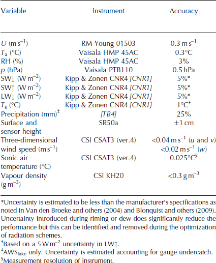
Due to restricted power supply, measurements of T a were made in an unventilated radiation screen (ten-plate Gill radiation shield). The lack of artificial ventilation produced heating of the sensor and an overestimation of T a during periods of high solar radiation and low wind speed (Reference SmeetsSmeets, 2006; Reference Huwald, Higgins, Boldi, Bou-Zeid, Lehning and ParlangeHuwald and others, 2009). To develop a correction to remove the positive bias, uncorrected air temperature from AWSglacier (T hmp) was compared to humidity-corrected sonic air temperature (T csat) using eddy covariance measurements over a midsummer ice surface from 8 to 16 February 2011 and over a spring snow surface from 27 October to 3 November 2011. These two short periods (total 16 days) were characterized by moderate U (means of 2.8 and 2.5 m s−1, respectively), with a range in T hmp from −2 to 10°C and −2 to 7°C, respectively. Outgoing shortwave radiation (SW↑) was lower in the ice period (mean of −149 W m−2 and maximum of −543 W m−2) than the snow period (mean of −187 W m−2 and maximum of −614 W m−2). Details of the eddy correlation measurements obtained over the ice surface are described by Reference Conway and CullenConway and Cullen (2013).
Before comparison to AWS measurements, T csat was corrected for the influence of humidity variations on the speed of sound using the method of Reference FokenFoken (2008), after Reference Kaimal and FinniganKaimal and Finnigan (1994). This required e a to be calculated with uncorrected T csat and RH from AWSglacier using the equations of Reference BuckBuck (1981). The calculation of e a and the humidity correction to T csat were performed in an iterative loop as the initial estimate of e a was an overestimation (due to uncorrected sonic air temperature being higher than absolute air temperature), and hence the initial reduction in T csat was too large. T csat converged in four to five iterations, with the result being a reduction in mean T csat of 0.8°C.
The humidity-corrected sonic temperature data (T csat) agreed well with T hmp during the night-time when solar heating was absent (Fig. 3). A bias in T hmp of up to 2.6°C was observed during the daytime, with an average deviation of 0.9°C during the ice period of eddy covariance measurements. Comparison with the spring snow period in October 2011 showed much larger offsets (daytime mean deviation 1.4°C), due in part to the lower wind speeds experienced, but also likely due to the much higher albedo during this period.
Comparison between 30 min means of humidity-corrected sonic air temperature (T csat) and uncorrected AWSglacier air temperature (T hmp) during eddy covariance measurement periods from 8 to 16 February 2011 (ice) and 27 October to 3 November 2011 (snow).
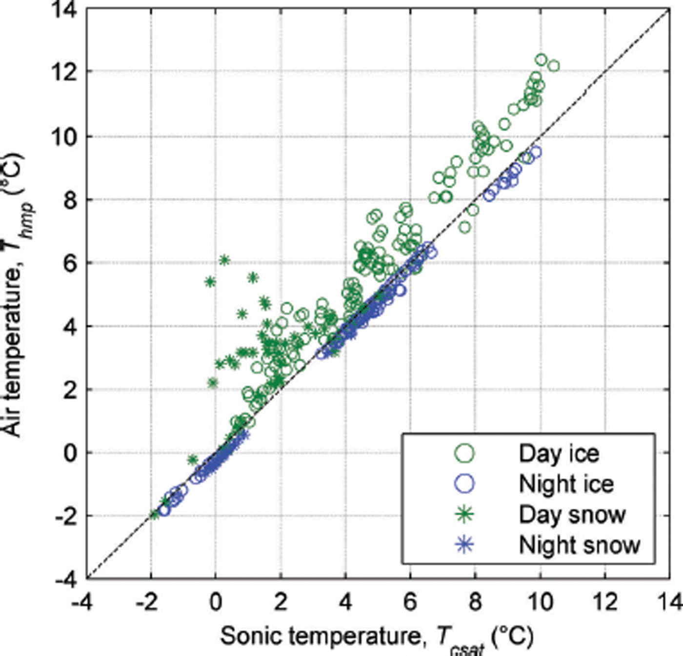
To compute the sensor heating correction the daytime residual (T csat − T hmp) was fitted to reflected SW↑ and U data from AWSglacier, after first removing the mean bias during the night-time. The expression
produced the best fit, where T a is air temperature at AWSglacier corrected for solar heating and the value of the coefficient was determined by least-squares regression. The form of the equation is similar to that in Reference Huwald, Higgins, Boldi, Bou-Zeid, Lehning and ParlangeHuwald and others (2009), except that it strengthens the dependence on SW↑, by applying the square root to U only, as opposed to the product of SW↑/U, as in Reference Huwald, Higgins, Boldi, Bou-Zeid, Lehning and ParlangeHuwald and others (2009). Applying the correction (r = 0.996) successfully removed the positive bias between T csat and T a and reduced root-mean-squared differences (RMSD) during the two short eddy covariance periods to less than the manufacturer’s specification (0.3°C). The smallest RMSD was found using SW↑ (0.25°C), rather than SW↓ (0.34°C) or SW↑ + SW↓ (0.30°C) in Eqn (1). The poorer performance when using SW↓ or SW↑ + SW↓ is likely due to the change in albedo between ice and snow surfaces and the dominant role that reflected radiation plays in controlling the magnitude of sensor heating (Reference Huwald, Higgins, Boldi, Bou-Zeid, Lehning and ParlangeHuwald and others, 2009). Figure 4 depicts the magnitude of corrections made at AWSglacier.
Correction made to air temperature (T a) for solar heating over the specified range of wind speed (U) and reflected shortwave radiation (SW↑) conditions.
Applying the correction to the full AWSglacier dataset (n = 32 544) resulted in a 0.4°C decrease in mean T a, with 73% and 94% of the decrease to individual 30 min values less than 0.5 and 2.0°C, respectively. On a monthly basis, the decrease in T a was largest in November (0.7°C) and December (0.8°C) due to snow cover and high values of SW↓. For comparison, the correction of Reference Huwald, Higgins, Boldi, Bou-Zeid, Lehning and ParlangeHuwald and others (2009) resulted in a 0.6°C decrease in mean air temperature, with 60% and 92% of the decrease to individual 30 min values less than 0.5°C and 2.0°C, respectively.
Scaling precipitation dataset to include winter precipitation
Measurement of precipitation at AWSlake was only possible during the summer months as deep snow covered the rain gauge during winter and spring. Analysis of snow depth and albedo at AWSlake allowed the periods of reliable precipitation data to be identified as 27 December 2010 to 27 April 2011 and 12 December 2011 to 12 May 2012. To account for gauge undercatch a factor of 1.25 was applied to the precipitation data recorded at AWSlake, which is between the rainfall and mixed rain/snow estimates of undercatch following the method of Reference Yang, Goodison, Ishida and BensonYang and others (1998). Application of the method described by Reference Yang, Goodison, Ishida and BensonYang and others (1998) resulted in gauge undercatch ranging between 18% and 37% depending on the thresholds used to determine different forms of precipitation. Without knowledge about the specific thresholds for rainfall and mixed rain/snow, applying a simple amplification factor was preferred. The factor is consistent with the anticipated undercatch from rain gauges used by Reference Henderson and ThompsonHenderson and Thompson (1999), who reported on intense rainfall events in the Southern Alps, while larger than the highest values (20%) used by Reference Kerr, Owens and HendersonKerr and others (2011) in the Lake Pukaki catchment of the Southern Alps.
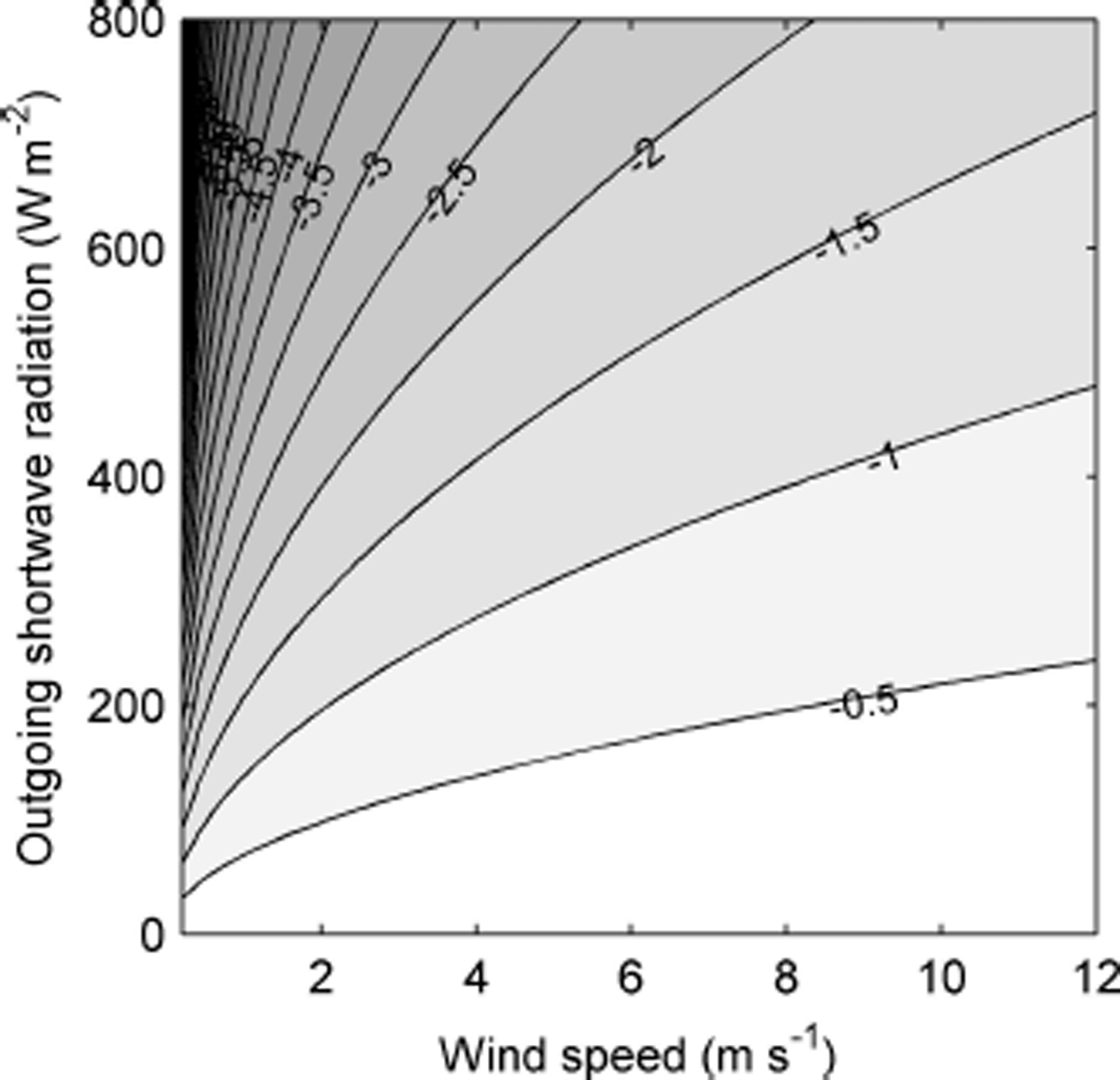
To construct a precipitation dataset at AWSglacier for the entire measurement period, precipitation at AWSlake (P lake) was compared to precipitation measured using a tipping-bucket rain gauge at Makarora (P makarora; Otago Regional Council), 30 km southwest of Brewster Glacier at 320 m a.s.l. The site was chosen as it represents a similar physiographic setting, being close to the main divide, and was at a low enough elevation not to be affected by significant snowfall during the winter months. Daily rainfall totals recorded at a site ∼200 m from the tipping-bucket measurements since 1961 (Makarora Station, NIWA) were also used to develop a precipitation normal for the site. The first period of reliable measurements (27 December 2010 to 27 April 2011) was chosen as the calibration period. Precipitation totals were compared at a range of block sizes (3, 6, 12 and 24 hours), with a block size of 6 hours deemed the most suitable as it helped overcome the problem of missing short events without compromising the assessment of temporal variability. Fitting a linear least-squares relationship to 6 hour totals (mm) at P lake and P makarora gave the equation
where P scaled is precipitation scaled to AWSlake (mm w.e.). Equation (2) was used to construct a precipitation dataset for the full study period. To validate the scaled precipitation dataset, the second period of reliable measurements between 12 December 2011 and 12 May 2012 was used. Figure 5 shows daily and 6 hour totals of observed and scaled precipitation, illustrating the adequate fit for both calibration and validation periods. During the validation period a tendency to slightly overestimate higher-magnitude events was shown by the divergence of the least-squares line of best fit, but in absolute terms the deviation was small. A number of periods with small values of P lake were not predicted by P scaled; however, the error associated with these periods was small as the average precipitation rate at AWSlake during these periods was 0.3 mm h−1 (maximum 2.5 mm h−1). The difference between modelled and observed precipitation totals for each period was <10%.
(a) Daily and (b) 6 hour precipitation totals observed (P lake) and modelled (P scaled) for calibration (closed circles) and validation (open circles) periods. Least-squares best-fit lines and R 2 values are shown for calibration (black), validation (blue) and combined periods (red).
Constructing a continuous surface height record
A four-step procedure was developed to construct a reliable and continuous record of surface height change, which was also used to monitor variability in sensor height: (1) remove poor-quality or erroneous data (SR50a signal quality >190 or <160, raw distance measurement <0.3 m), (2) correct raw distance measurement for air temperature difference from 0°C, (3) linearly interpolate between the remaining quality-controlled and corrected distance measurements to original 30 min timestamp and (4) smooth using a convolution filter with a 2 hour time-step length. Visual inspection of the final dataset showed a good representation of the temporal evolution of surface height, while being consistent with the remaining data points (79% of original data). The continuous dataset enabled surface height change to be calculated over 24 hour periods (midnight to midnight), while also providing a high-quality product for mass-balance model validation (Reference Conway and CullenConway and Cullen, 2015).
Radiation components
Maintaining level instruments on the single mast used to support AWSglacier proved difficult during the first summer of measurements. During a period of high ablation rates over the predominately ice surface from January to March 2011, some tilt of the mast was experienced, despite the long (6 m) pole. The SW↓ data during these times were corrected back to a horizontal reference plane using the method of Reference Van AsVan As (2011) using measurements of mast zenith and azimuth made at periodic (3–20 days) site visits. The method uses the geometric relationships between the solar beam and plane of measurement on the instrument, scaling the direct radiation fraction only and accounting for the increase of the diffuse fraction during cloud cover using measured LW↓. A longer sectioned pole (12 m) installed in October 2011 removed problems associated with tilt of the mast during the second ablation season. Incoming shortwave radiation data were also rotated relative to the glacier surface for use in surface energy-balance calculations, again using the method of Reference Van AsVan As (2011). Due to their more isotropic distribution, measurements of SW↑, LW↓ and outgoing longwave radiation (LW↑) are not as sensitive to tilt, so these data were not corrected. LW↓ data were corrected for solar heating of the sensor window (Reference Sicart, Wagnon and RibsteinSicart and others, 2005), but the correction proposed by Reference Giesen, Andreassen, Oerlemans and Van den BroekeGiesen and others (2014) was not adopted.
During heavy snowfalls the upper radiation sensors were sometimes covered in snow, compromising SW↓ measurements. These periods were identified by detecting large values in accumulated albedo (α acc), which was calculated as the ratio of the sum of SW↑ and the sum of SW↓ over a day (Reference Van den Broeke, Van As, Reijmer and Van de WalVan den Broeke and others, 2004). On days when α acc exceeded 0.95 (albedo of fresh snow), SW↓ was calculated as SW↓ = SW↑/0.95 (Reference Oerlemans and KlokOerlemans and Klok, 2002). The value selected for the albedo of fresh snow (0.95) is at the upper end of reported values but consistent with the threshold used by Reference Andreassen, Van den Broeke, Giesen and OerlemansAndreassen and others (2008).
Model description
A mass-balance model, described in detail by Reference Mölg, Cullen, Hardy, Kaser and KlokMölg and others (2008, Reference Mölg, Cullen, Hardy, Winkler and Kaser2009, Reference Mölg, Maussion, Yang and Scherer2012), was used to resolve the surface energy-balance terms described in this study, while the atmospheric controls on the mass-balance terms, specifically the mass gains (solid precipitation, surface deposition, refreezing of liquid water in the snow) and mass losses (surface and subsurface melt, surface sublimation), are the focus of the study by Reference Conway and CullenConway and Cullen (2015). To solve the surface energy balance, the maximum number of measurements available were used to force the model at 30 min time steps: SW↓, LW↓, α acc, T a, RH, U and air pressure. This input was used to determine LW↑ (from the calculated surface temperature, T s), the turbulent sensible (QS) and latent (QL) heat fluxes, the conductive heat flux (QC) and the energy flux from precipitation falling as rain (QR). The latter is an important contributor to the surface energy balance during summer and was calculated using P scaled, assuming rain temperature is equal to air temperature (T a). P scaled data were used to calculate the amount of fresh snow using a rain/snow threshold of 1°C and a density of 300 kg m−3 (Reference Gillett and CullenGillett and Cullen, 2011). The sign convention used is that all fluxes directed towards the surface are positive, with the exception of the energy available for melt (QM), which is defined as the sum of all other fluxes and is therefore a positive term.
An iterative surface energy-balance closure scheme implemented by Reference Mölg, Cullen, Hardy, Kaser and KlokMölg and others (2008) was used to calculate T s, enabling QC to be calculated as the flux between the surface and the top layer of the 12-layer subsurface module (0.1, 0.2, 0.3, 0.4, 0.5, 0.8, 1.4, 2, 3, 5 and 7 m). The depth, density and temperature of the initial snowpack (isothermal at 0°C) were taken from snow-pit measurements, while the bottom temperature in the subsurface module was held fixed at 0°C. Surface liquid water (melt + rainfall + condensation − evaporation) was refrozen in the snowpack when the bulk temperature (vertically integrated through the entire snowpack) was <0°C. Settling and compaction of the snowpack due to viscous deformation were included (Reference Sturm and HolmgrenSturm and Holmgren, 1998), allowing for increases in snow density and realistic snow depths. A failure to obtain reliable subsurface temperature profile data prevented the penetrating shortwave radiation scheme from being optimized, so it was not implemented in this study. The turbulent heat fluxes, QS and QL, were calculated using a C log parameterization (Reference Conway and CullenConway and Cullen, 2013), using roughness lengths for momentum (z 0v ), temperature (z 0t ) and moisture (z 0q ) calculated from eddy correlation measurements over an ice surface (z 0v = 3.6 × 10⁻³ m, z 0t = z 0q = 5.5 × 10⁻⁵ m). The sensitivity of the mass-balance model to changes in roughness lengths and other input parameters is assessed by Reference Conway and CullenConway and Cullen (2015) using a Monte Carlo approach over the same measurement interval. Importantly, good agreement between modelled and observed surface temperature (as determined from radiation measurements) at 30 min time steps was observed (Reference Conway and CullenConway and Cullen, 2015), with the mean bias error (MBE) and RMSD equal to 0.2°C and 1.1°C, respectively. This agreement is important, as modelled surface temperature determines all surface fluxes except net shortwave radiation (SWNET) and LW↓, and affects the proportion of energy available for melt, giving us confidence in the surface energy-balance terms we present in the following section.
Results
Comparison of study period to long-term climatological records
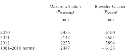
An examination of long-term precipitation records at Makarora shows that annual precipitation during the study period was around or slightly below normal (Table 2). The approach used to estimate a long-term precipitation normal on Brewster Glacier reveals it likely exceeds 6000 mm w.e. a−1, which is higher than previously reported (Reference AndersonAnderson and others, 2010) but consistent with mass-balance observations and modelling (Reference Conway and CullenConway and Cullen, 2015). Precipitation was slightly below normal in most seasonal periods (Fig. 6), with the exception of December–February (DJF) 2010/11, which received large totals in all three months and was 1.8 times greater than normal. Periods in 2010 and 2012, before and after the main study period, respectively, also received above-average precipitation (not shown).
Summary of annual precipitation at Makarora Station and Brewster Glacier. The 1981–2010 annual precipitation normal at Brewster Glacier is estimated using a least-squares fit of annual precipitation at the two sites over the period 2010–12
Comparison of mean monthly air temperature at AWSglacier (lines) and 3 monthly precipitation totals at Makarora (bars) during the study period (blue) to 1981–2010 normals (green). Air temperature normals for AWSglacier were constructed using the normals for Haast AWS adjusted for the mean difference between AWSglacier and Haast AWS (10.4°C).
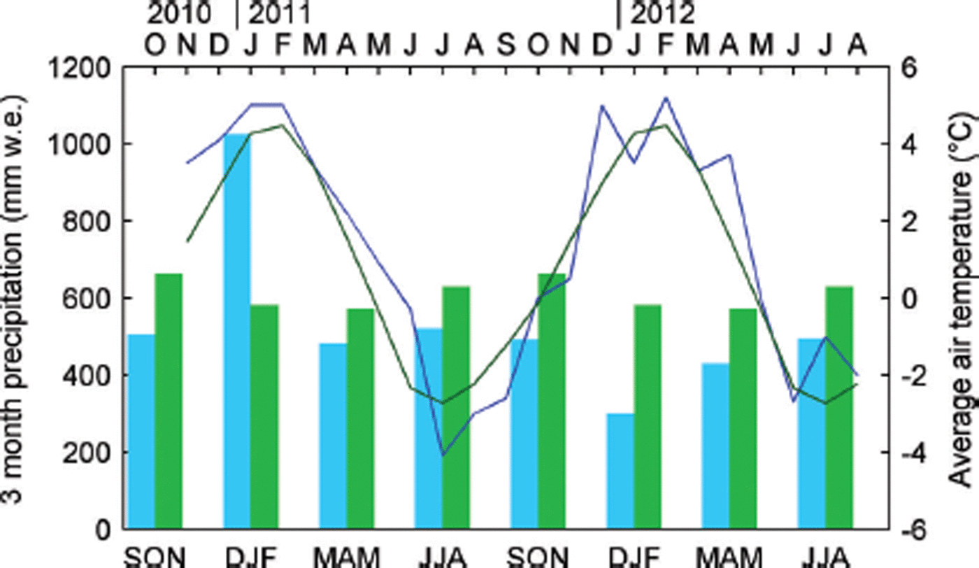
The closest long-term air temperature record to Brewster Glacier is the Haast AWS at 5 m a.s.l., which is ∼40 km northwest of Brewster Glacier and 1 km from the Tasman Sea on the west coast of the South Island. The variability in monthly mean T a at Haast AWS shows a good correspondence to that at AWSglacier (Fig. 6). The mean difference in T a between the sites during the study period (10.4°C) suggests the lapse rate was 0.0059 K m−1, similar to that found by Reference Mark, Dickinson and HofstedeMark and others (2000). Monthly T a anomalies show the first ablation season (2010/11) was characterized by above-normal T a and the second (2011/12) by more variable T a. The higher T a during 2010/11 persisted well into autumn (March–May (MAM)) and early winter (June), with positive departures of up to 2°C from normal. On average, T a at Haast AWS was 0.5°C higher than the 1981–2010 normal over the study period. The warm, wet conditions during DJF 2010/11 were due to persistent northwesterly winds that brought frequent episodes of warm subtropical air over the South Island.
In summary, the study period was characterized by higher T a values than average, while the two summer periods contained in the record had above- and below-normal precipitation. The glaciological data obtained on Brewster Glacier indicate the 2010/11 and 2011/12 mass-balance years (1 April to 31 March) were characterized by negative mass balance (−1.7 and −0.6 m w.e. a−1, respectively), with 2010/11 the most negative in the 11 year series (2005–15). Thus, the study period is likely to be more representative of negative mass-balance trends compared to observations of positive mass balance in the Southern Alps between the early 1980s and 2000 (e.g. Reference Chinn, Winkler, Salinger and HaakensenChinn and others, 2005).
Temperature, relative humidity, wind speed and atmospheric pressure
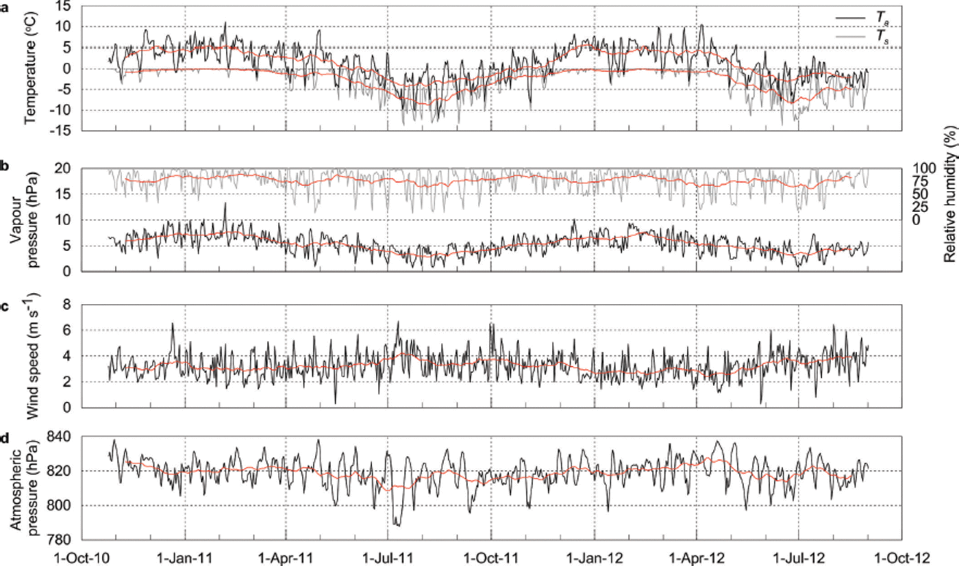
The meteorological conditions at AWSglacier during the study period are shown in Figure 7. Air temperature showed a clear seasonal cycle around a mean value of 1.2°C (Table 3). Mean monthly T a was only below freezing for 4 months (June–September) of the year, while February was the warmest month. The seasonal variability in T a was small, with the monthly range equal to 7.7°C. Large daily variability was observed (standard deviation when calculating monthly means was 2.7°C), with daily means above and below 0°C in all seasons (Fig. 7a). Frequent changes in the synoptic conditions at this temperate, maritime location were responsible for the large daily variability in T a. Surface temperature (T s) showed moderate seasonal variability, with daily means around 0°C during summer. Surface temperature was consistently lower than T a during winter (stable atmospheric conditions).
Mean daily atmospheric conditions at AWSglacier over the study period. (a) Air (black) and surface (grey) temperature; (b) atmospheric vapour pressure (black) and relative humidity (grey); (c) wind speed; and (d) atmospheric pressure. The red lines are the 31 day running means.
Mean monthly values of meteorological, radiation and surface energy-balance variables
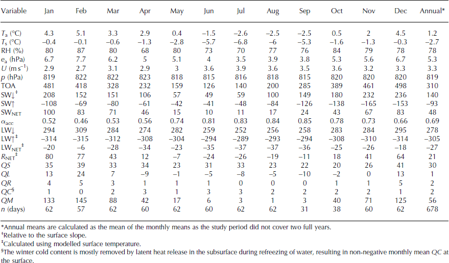
Variations in monthly RH were observed (Table 3), with the standard deviation of daily mean RH equal to 20%. A small trend towards lower RH in winter can be observed, with minimum daily RH < 25% during April to August (Fig. 7b). A large proportion (44%) of periods had RH > 90%, largely controlled by Brewster Glacier’s close proximity to moisture sources (e.g. Tasman Sea and Pacific Ocean). Atmospheric vapour pressure closely followed T a, with monthly mean values above that of a melting surface (6.11 hPa) through summer and below this threshold during winter (Table 3). Mean wind speed (U) during the study period was 3.3 m s−1 and exhibited day-to-day variability (standard deviation = 0.9 m s−1), with a small rise during winter (Fig. 7c). Atmospheric pressure (p) at the site ranged from 790 to 840 hPa, with a small seasonal cycle peaking in February (Fig. 7d). The temporal variability in atmospheric pressure also clearly demonstrates how rapidly synoptic conditions can change over the Southern Alps.
Precipitation and surface height change
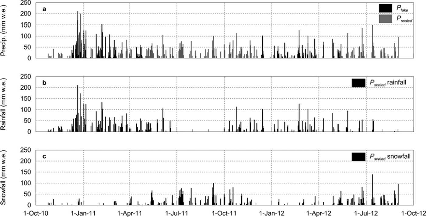
Precipitation was frequent throughout the 22 month study period, with an estimated total of 9894 mm w.e. falling on the lower part of the glacier (Fig. 8a). Using a rain/snow threshold of 1°C, it was estimated that a larger amount fell as rain (58%) than snow (42%). Rain was largely absent at the site from July to October (Fig. 8b), while periods of snowfall were evident during both summer periods (Fig. 8c). The increased precipitation during DJF 2010/11 is evident, with maximum daily totals in excess of 200 mm w.e. during this period.
Daily total precipitation during the study period for AWSglacier. (a) Comparison between P lake and P scaled; (b) estimated rainfall; and (c) estimated snowfall. The approach used to calculate P scaled is described in the text.
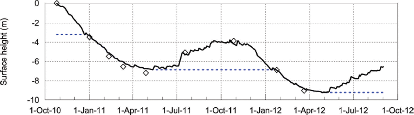
The glacier surface at AWSglacier experienced large height changes during the study period (Fig. 9). During the 2010/11 (2011/12) ablation season, 3.2 (3.0) m of snow and 3.7 (1.6) m of ice were removed at the location of AWSglacier. The snow–ice transition occurred in the first few weeks of January in both seasons, and melting of ice at the surface continued until 11 May 2011 and 29 April 2012, respectively. Winter accumulation was 3.2 m in 2010 and 3.0 m in 2011, while 4.6 m of accumulation was recorded on 30 October 2012 using probe measurements. The agreement between the surface height record, mass-balance measurements (ablation-stake and snow-pit measurements) and estimated accumulation from P scaled (snowfall) gives us confidence that the total amount of precipitation and threshold for rain/snow were appropriate. A detailed comparison between the surface height change and modelled mass balance is provided by Reference Conway and CullenConway and Cullen (2015).
Surface-height changes at AWSglacier during the study period. The black line is a compilation of surface height from sonic rangers on both AWSglacier and the adjacent tripod, while the dashed blue lines show the approximate level of the ice surface. The diamonds show surface height changes calculated from periodic ablation stake measurements during the summer and snow-pit measurements in the winter and spring.
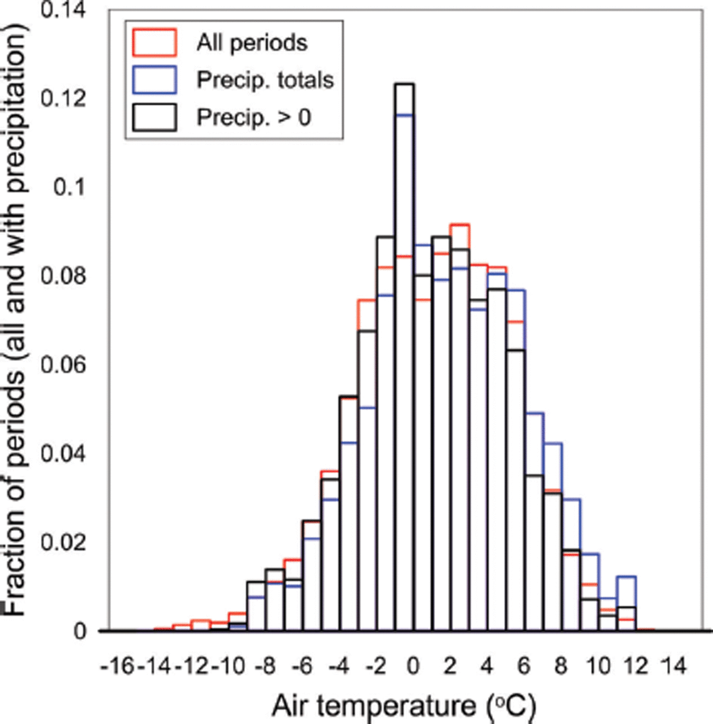
The distribution of T a during periods of precipitation showed only small deviations from the distribution of T a during all periods, with a broad peak around 1°C (Fig. 10). When precipitation in each temperature bin was divided by total precipitation over the period, a small positive bias was observed, which indicates large precipitation totals were associated with high T a. Precipitation was absent for the very lowest T a bins, which were associated with nocturnal cooling. A curious feature of the distribution is the mode at −1 to 0°C, which is difficult to find a physical explanation for. If it is not a measurement artefact it would suggest that when snow fell it most frequently did so when T a was just below freezing. Regardless, it is striking how much of the annual precipitation fell within ±3°C of the rain/snow threshold. The implication of this is twofold. First, the amount of precipitation estimated to fall as rain or snow is very sensitive to the method chosen to define the threshold. For example, if the rain/snow threshold used in this study (1°C) had been equal to 0°C, 34% more snow would have been predicted to fall or, alternatively, had the rain/snow threshold been 2°C the snowfall would have been reduced by 50%. Second, any small changes in T a due to climate change will have a large effect on Brewster Glacier, and glaciers in the Southern Alps in general, through changes in precipitation type and the associated albedo feedback (Reference Conway and CullenConway and Cullen, 2015).
Distribution of air temperature at AWSglacier during all periods (red) and periods with precipitation (Precip. > 0) (black). Precipitation totals shown in blue are total precipitation in each temperature bin divided by total precipitation over the period.
Surface-atmosphere temperature and humidity gradients
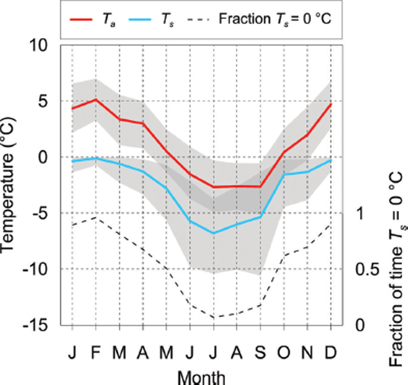
Surface temperature showed a distinct seasonal cycle during the study period, reaching melting point >90% of the time during summer and <10% of the time during winter (Fig. 11). The moderate frequency of non-melting conditions during summer is consistent with that found by Reference Gillett and CullenGillett and Cullen (2011), confirming that the assumption the surface is always melting may lead to inaccuracies in modelled ablation (Reference Pellicciotti, Carenzo, Helbing, Rimkus and BurlandoPellicciotti and others, 2009), even at this temperate, maritime site during summer. As shown in Figure 11, mean daily maximum T s and minimum T a converged in spring (grey shading), as the peak in T a lagged the peak in SW↓ by more than a month. Thus, in winter and spring, there was a higher frequency of periods when T s exceeded T a, which led to unstable conditions (Fig. 12). However, instability only accounted for 11% of all atmospheric conditions on an annual basis, emphasizing that stable conditions, and hence positive sensible heat fluxes, dominated over the glacier surface.
Monthly mean air temperature (T a) and surface temperature (T s) during the study period. The shaded boxes give the average daily maximum and minimum for each. The dashed line indicates the fraction of time the surface is likely to be melting. To account for ±1°C uncertainty in the measured surface temperature, periods were selected using a conservative threshold of -1°C. Thus, the values shown represent an upper limit on the fraction of melting periods.
A seasonal trend in the direction of the vapour pressure gradient was also observed, with evaporation/sublimation more common in winter and condensation/deposition more common in summer (Fig. 12). This trend was controlled in part by the tendency of e a to be lower during winter, but also by T s being limited to 0°C in summer. On average, about half of all periods (49%) showed negative vapour pressure gradients (implying deposition of mass to the surface). The magnitude of the sensible and latent heat fluxes is described in the following subsection.
Fraction of 30 min blocks where surface temperature (T s) exceeded air temperature (T a) (red) and surface vapour pressure (e s) exceeded atmospheric vapour pressure (e a) (blue). These represent the fraction of unstable conditions and the fraction of evaporation/ sublimation versus condensation/deposition, respectively.

Surface radiation and energy fluxes
Incoming shortwave radiation varied strongly with season, with maximum daily values >400 W m−2 during midsummer and 80 W m−2 during midwinter (Fig. 13a). Interestingly, minimum daily values of SW↓ during summer were similar to those during winter, despite incoming solar radiation at the top of atmosphere (SWTOA) being four times larger in summer. This indicates the large effect that clouds have on the variability of SW↓. Over the study period, average SW↓ was 46% of SWTOA, indicating a large amount of absorption and scattering of solar radiation by atmospheric constituents, including clouds. The high average albedo resulted in only 15% of SWTOA being absorbed at the surface (SWNET). Variability in albedo enables a clear distinction between snow (0.6–0.95) and ice (0.35–0.5) to be observed, while numerous summer snowfalls can be seen in the albedo record (Fig. 13b). The snow albedo was much higher in midwinter (0.8–0.95) than late winter and spring (0.6–0.8). Figure 13b also shows a difference in the ice surface albedo between the two seasons. The controls on this variability are unclear, but an increase in localized sediment content in summer 2012 may have contributed to the lower albedo observed.
Daily means of (a) incoming radiation fluxes and (b) albedo at AWSglacier during the study period.

Incoming longwave radiation fluctuated around a mean value of 278 W m−2, significantly larger than SW↓ during the winter months (Fig. 13a). An inverse relationship between day-to-day variability in SW↓ and LW↓ can be observed, with periods of decreased SW↓ associated with increased LW↓, indicating cloud cover (e.g. July 2012). Net shortwave radiation peaked in January in response to the shift to a predominately ice surface at the site (Fig. 14a). Net longwave radiation (LWNET) was generally negative (Fig. 14b), though positive values during the summer months were not uncommon in association with small SWNET (cloudy conditions) and a melting glacier surface that limited LW↑ to -316 W m−2. Thus, despite the small fraction of SWTOA absorbed by the glacier surface, the small magnitude of LWNET losses enabled net radiation (R NET) to be positive on an annual basis (Table 3), with a distinct seasonal cycle evident (Fig. 14c). The positive R NET is equivalent to the energy required to melt 2.2 m of ice (assuming a density of 900 kg m−3).
Daily means of (a) SWNET, (b) LWNET, (c) R NET, (d) QS, (e) QL, (f) QR and (g) QM at AWSglacier during the study period. The blue line in each panel is a weekly running mean.

Figure 14d shows that QS was directed primarily towards the surface, as controlled by temperature gradients (Fig. 12). In winter, QS was of equal magnitude to LWNET, compensating for the surface radiative cooling. In contrast, a more distinct seasonal cycle of QL can be observed (Fig. 14e), with sublimation and/or evaporation more likely to occur between April and October (Table 3). The latent heat flux was much smaller in magnitude than QS in all months, but important as an energy source for ablation during summer (i.e. condensation on the surface). The energy associated with rainfall was negligible during winter, but in summer was important during heavy rainfall events (Fig. 14f). The conductive heat flux (QC) was negligible during summer (isothermal), while nocturnal cooling of the surface and subsurface resulted in small heat transfers towards the surface during winter (Table 3).
The energy available for melt (QM) followed the seasonal cycle of SWNET, with variability controlled by fluctuations in QS, QL and QR. Figure 14g shows that QM was largest during summer, but that melting occurred in all months (Table 3). The main melt season was between November and March, with 83% of the ablation occurring during this period. Though less significant energetically, October and April were responsible for 12% of the annual energy budget for melt, with the remainder (5%) occurring between May and September. The highest modelled value of daily QM during summer was 443 W m−2 (Fig. 14g), associated with a precipitation event, which resulted in the mass loss of 115 mm w.e. d−1. During the summer months (December–February), energy available for melt was equivalent to 35 mm w.e. d−1, which is slightly less than observed by Reference Gillett and CullenGillett and Cullen (2011) over a shorter period in summer (40 mm w.e. d−1).
Discussion
Comparison to other multi-annual glacier climate records
Although a 22 month record does not constitute a climatology, the meteorological observations obtained in this study have allowed the key physical processes controlling the seasonal variation in surface energy balance in the ablation zone of Brewster Glacier to be identified. Compared to previous surface energy-balance studies in the Southern Alps that have described the atmospheric controls on glacier ablation during short periods in summer (e.g. Reference Marcus, Moore and OwensMarcus and others, 1985; Reference Hay and FitzharrisHay and Fitzharris, 1988a,Reference Hay and Fitzharrisb; Reference Ishikawa, Owens and SturmanIshikawa and others, 1992; Reference Kelliher, Owens, Sturman, Byers, Hunt and SeveneyKelliher and others, 1996; Reference Cutler and FitzharrisCutler and Fitzharris, 2005; Reference Gillett and CullenGillett and Cullen, 2011), we have been able to present the full seasonal cycle of the surface energy balance. Importantly, it has been shown that melt (QM) can occur in all months on the lower part of Brewster Glacier (Table 3). During periods confined to melting, R NET is the largest source of energy for ablation (88 W m−2), accounting for 64% of QM (Table 4), which is larger than previously reported (e.g. Reference Hay and FitzharrisHay and Fitzharris, 1988b; Reference Gillett and CullenGillett and Cullen, 2011). The main contributor to R NET during melt (QM > 0) is SWNET, which is sensitive to changes in surface albedo and variability in cloud conditions (Reference Conway and CullenConway and Cullen, 2015). The turbulent sensible heat flux is the next largest energy source (23%) during melt, followed by QL (11%) and QR (4%), while QG is a small heat sink (-2%). While the turbulent heat fluxes can make significant contributions to ablation during specific synoptic conditions on Brewster Glacier (Reference Gillett and CullenGillett and Cullen, 2011), they are not the primary energy source for melt during summer.
Comparison of the geographic characteristics, meteorological conditions and surface energy balance for a selection of glaciers (and an ice-sheet margin) that have obtained multi-annual meteorological records in an ablation zone. Square brackets give values during periods of surface melt (June–August for S5, West Greenland ice sheet), calculated from hourly values for Brewster Glacier. The T a range is the temperature difference between the warmest and coldest months. Vapour pressure is converted to specific humidity (q) using q=0.622 × e a/p. Values are taken from Reference Oerlemans, Giesen and Van den BroekeOerlemans and others (2009), Reference Giesen, Andreassen, Van den Broeke and OerlemansGiesen and others (2009, Reference Giesen, Andreassen, Oerlemans and Van den Broeke2014) and Reference Van den Broeke, Smeets and Van de WalVan den Broeke and others (2011), with the temporal periods for each given in the footnotes. The sites chosen for comparison were selected due to the similarity of the instrumentation used and consistency in the point-based surface energy-balance modelling
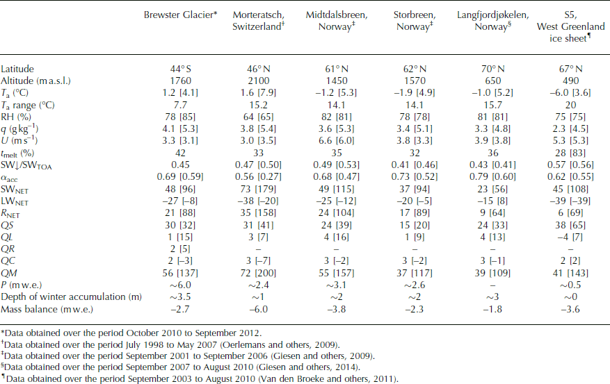
Because of the logistical challenges involved, very few long-term meteorological records over glacier surfaces exist. However, a very good comparison between records obtained on glaciers in Norway and other surface energy-balance studies is provided by Reference Giesen, Andreassen, Van den Broeke and OerlemansGiesen and others (2009, table 3). To provide further comparison, we compare our meteorological and surface energy-balance information to point data obtained from the ablation zone of three glaciers in Norway and two other mid- and high-latitude glaciers in the Northern Hemisphere (Table 4). The meteorology over Brewster Glacier, which has the lowest latitude of the six glaciers compared, shows some important differences (and similarities) to the others. Firstly, the amplitude of the seasonal cycle in T a is much smaller than in areas in the European Alps, Norway and on the western margin of the Greenland ice sheet, indicative of the temperate, maritime conditions of the Southern Alps. Although mean annual T a is comparable to that observed over Morteratsch glacier, Switzerland, both summer and winter values of T a are not as extreme on Brewster Glacier. During melt periods, T a on Brewster Glacier is similar to that on glaciers in Norway and on the western margin of the Greenland ice sheet, despite their much higher latitude. The effect of the small amplitude in seasonal T a and high RH is to increase the length of the melt season on Brewster Glacier compared to the other locations. Atmospheric transmission of solar radiation is less than observed on the Greenland ice sheet and Morteratsch glacier but similar to that on the monitored glacier in Storbreen, Norway, reflecting the large influence of clouds at these locations (Reference Giesen, Andreassen, Van den Broeke and OerlemansGiesen and others, 2009, Reference Giesen, Andreassen, Oerlemans and Van den Broeke2014; Reference Conway and CullenConway and Cullen 2015; Reference Conway, Cullen, Spronken-Smith and FitzharrisConway and others, 2015).
Further similarities between the glaciers in Norway and Brewster Glacier were identified by comparing the surface energy-balance terms (Table 4). It is clear that cloudy conditions strongly influence LWNET during melt conditions, with enhanced LW↓ reducing energy loss at the surface, even resulting in a positive LWNET on average at Langfjordjøkelen (Reference Giesen, Andreassen, Oerlemans and Van den BroekeGiesen and others, 2014). While LWNET remains positive on cloudy melt days on Brewster Glacier, energy losses at the surface during clear-sky conditions result in LWNET being slightly negative, on average, during melt. Annually, the turbulent heat fluxes are directed towards the surface at all locations, with the exception of West Greenland where sublimation dominates over deposition. The contribution of R NET to melt is greater than the turbulent heat fluxes at all sites except West Greenland, with the importance of R NET on Brewster Glacier (64%) similar to glaciers in Norway. Of the glaciers compared, Morteratsch glacier is the most energy-rich environment during summer, with high QM largely controlled by SWNET. While smaller, the energy available for melt on Brewster Glacier and glaciers in Norway are alike, with the mass loss on the four glaciers in hydrological units ranging between 28 and 40 mm w.e. d−1.
The large and relatively even distribution of precipitation throughout the year is perhaps the most contrasting feature of the climate on Brewster Glacier compared to other locations. Precipitation during the 2010–12 period was slightly less than 6000 mm w.e. a−1, which far exceeds the other glacier sites despite being lower than the long-term normal (Table 2). Very large precipitation totals were recorded during the summer months at Brewster Glacier, with the majority of this falling as rain (Fig. 8). The hydrological response of rain-on-snow (and -ice) events in the Southern Alps is not well understood, but it is clear that rain is an important energy source to ablation in summer on Brewster Glacier (Fig. 14g). Most surface energy-balance studies neglect the contribution of rain to ablation (e.g. Reference Anslow, Hostetler, Bidlake and ClarkAnslow and others, 2008; Reference Giesen, Andreassen, Van den Broeke and OerlemansGiesen and others 2009, Reference Giesen, Andreassen, Oerlemans and Van den Broeke2014), but in the Southern Alps its role in large melt events cannot be overlooked (Reference Owens, Marcus and MooreOwens and others, 1984; Reference Hay and FitzharrisHay and Fitzharris, 1988b; Reference Gillett and CullenGillett and Cullen, 2011). It is also striking how much of the annual precipitation on Brewster Glacier falls very close to the rain/snow threshold. As already noted, small changes in the temperature structure of moisture-bearing air masses will therefore have a strong influence on the amount of snow accumulation in the future.
Conclusions
A 22 month meteorological record has been presented from the ablation zone of Brewster Glacier. A distinct but low-amplitude seasonal cycle of air temperature was observed around a mean annual value of 1.2°C. Large variations in daily T a were observed, with daily average values above and below 0°C in all months, demonstrating that air mass changes have a pronounced effect on the variability of T a. In comparison to a selection of glaciated areas in the Northern Hemisphere, the small amplitude of the annual cycle in T a and consistent precipitation throughout the year are the most defining features of the climate on Brewster Glacier.
The long-term annual mean precipitation at Brewster Glacier likely exceeds 6000 mm w.e. a−1. Significant precipitation was observed in every month of the study period, with the two summer periods showing contrasting high and low precipitation totals, respectively. The association of enhanced precipitation with increased T a during summer 2010/11 emphasizes the maritime location of the Southern Alps, where changes in the source area of air masses impinging on the Southern Alps can force large anomalies in T a that are not associated with the positive relationship between summertime T a and local radiation balance seen in other areas (Reference Peixoto and OortPeixoto and Oort, 1992). The amount of precipitation that fell as rain (58%) was estimated to be slightly larger than that of snow (42%). However, as the majority of the precipitation fell very close to the freezing level, the proportion of snow versus rain is sensitive to the choice of rain/snow threshold. Combined with the strong synoptic control on T a, snow or rain can occur at any time of the year, enhancing the sensitivity of Brewster Glacier to any future change in T a.
Only weak seasonal variability in other meteorological variables (wind speed, relative humidity and atmospheric pressure) was observed. Surface temperature exhibited a moderate seasonal cycle and was at melting point 5–90% of the time on a monthly basis. Over the duration of the study period the surface was melting 42% of the time. Thus, even for this temperate, maritime site, the inclusion of non-melting conditions in surface energy-balance modelling is essential to correctly reproduce the direction and magnitude of the turbulent heat fluxes. A ∼6 week lag between cycles in SWTOA and T a was observed and appeared to be responsible for strong surface heating and unstable conditions during late winter and spring, though stable conditions otherwise prevailed over the glacier.
Seasonal variation in SW↓ and albedo, combined with periods of positive LWNET during cloudy periods, created a peak in R NET during January and February. While LW↓ was twice the magnitude of SW↓ on an annual basis, SWNET was a source and LWNET a sink to the surface energy balance. On average, QS was directed towards the surface and of equal magnitude to LWNET in winter. The latent heat flux was an important energy source during summer (condensation/deposition), but a shift to sublimation between April and October resulted in it being a small term annually. The energy associated with rainfall was negligible during winter, but was important during heavy summer rainfall events. The majority of the ablation occurred between November and March (83%), while October and April accounted for ∼12%. During periods confined to melting, R NET was the largest source of energy for ablation, accounting for 64% of QM. The main contributor to R NET during melt was SWNET, despite only 15% of SWTOA being absorbed by the glacier surface, indicating the large effect clouds have on radiation attenuation at Brewster Glacier. The turbulent heat fluxes accounted for just over a third of the energy for melt (34%), which is a similar proportion to glaciers in Norway (Reference Giesen, Andreassen, Oerlemans and Van den BroekeGiesen and others, 2014).
The next logical step in our efforts to improve understanding of the atmospheric controls on Brewster Glacier is to assess in more detail how changes in synoptic circulation influence impinging air masses over the Southern Alps. It is well known that synoptic circulation controls variability in glacier behaviour in the Southern Alps (e.g. Reference Fitzharris, Hay and JonesFitzharris and others, 1992, Reference Fitzharris, Chinn and Lamont1997; Reference Clare, Fitzharris, Chinn and SalingerClare and others, 2002; Reference Chinn, Winkler, Salinger and HaakensenChinn and others, 2005), but there is still a need to assess how air mass variability controls the surface energy balance both spatially and temporally over glacier surfaces. For example, any future prediction of glacier behaviour in the Southern Alps should consider the effects of atmospheric moisture on both ablation and accumulation (Reference Conway and CullenConway and Cullen, 2015). Establishing how synoptic circulation has varied through time and how these changes translate to variability in the surface energy balance will enable the physical processes controlling glacier behaviour in the Southern Alps to be better understood.
Acknowledgements
This research has been supported by the Department of Geography, University of Otago, and funded through a University of Otago Research Grant (ORG10-10793101RAT). The research also benefited from the financial support of the National Institute of Water and Atmospheric Research (Climate Present and Past CLC01202). The Department of Conservation supported this research under concession OT-32299-OTH. Chris Garden and Pascal Sirguey from the University of Otago helped to consolidate the mass-balance data and to determine the glacier boundary used in Figure 1.


