

I. INTRODUCTION
With the rapid development of global economy and industry, the number of vehicles increases dramatically, which inevitably results in excessive depletion of natural resources and thus increases the environmental pollution. As one green and clean transportation, the electric vehicle (EV) utilizes the electric energy instead of conventional fuel energy, which significantly reduces the demand for traditional natural resources and effectively relieves the pressure on our living environment [Reference Rezvani, Jansson and Bodin1]. However, the further development of EVs is significantly limited by the current battery technique, which cannot provide expected performance of energy storage in terms of the output power, energy density, endurance and cycle life [Reference Bräuer, Monof, Klör, Plenter, Beverungen and Siemen2]. Hence, an effective energy supplement is one of the most important technical issues for EVs. One solution is to build dedicated charging stations as many as possible, but it will inevitably take up plenty of additional urban land. Accordingly, the EV charging needs an innovative technique to replace the simple and extensive investment as aforementioned.
To address the problems above, the wireless power transfer (WPT) has attracted increasing attentions [Reference Braden, Bradley, Crabb, Zane, McGinty and Quinn3, Reference Germano and Perriard4], which enables the power to be transmitted from the supply to the load in a cordless way. As a novel energy access way, the WPT has capacities of making EVs harness the energy in the air. It means that the batter charging can be conducted without any physical contact, thus significantly enhancing the flexibility of acquiring the energy for EVs by comparing conventional plug-in charging systems. Then, WPT shows great potentials to bypass the technical limitation of current battery technologies and boost the further development and popularization of EVs. However, the current WPT technology still exists technical drawbacks, especially for the energy efficiency, effective transmission distance, misalignment tolerance, and electromagnetic disturbance.
In recent years, a great number of attempts have been carried out by academic researchers and industrial engineers around the world [Reference Musavi and Eberle5], which aims to improve the transmission performance of WPT systems. In particular, the emergence of metamaterials opens a brand new technical route for the development of WPT technologies [Reference Prat-Camps, Navau and Sanche6–Reference Oh and Lee12]. The metamaterial is an artificial material with special left-handed electromagnetic properties, such as the negative permeability, negative permittivity, negative refractive index, and evanescent wave amplification [Reference Wang, Teo, Nishino, Yerazunis, Barnwell and Zhang13]. Accordingly, there are increasing researchers who attempt to utilize the left-handed characteristics to shape the induced electromagnetic field and then improve the transmission performance of WPT systems. The existed studies have illustrated the effectiveness and advantages of metamaterial-based WPT systems, such as the enhanced transmission efficiency, the increased transmission distance, and the improved tolerance of positional misalignment. Undoubtedly, this emerging technique shows significant meanings for EV wireless charging systems.
The rest of this paper is organized as follows. Section II will review previous studies on the metamaterial, especially for its contributions to WPT technologies. In this section, this paper will first introduce the working principle and corresponding topologies of metamaterials. In addition, the existed studies on metamaterial-based WPT technologies will be summarized and discussed with emphasis on the energy efficiency, misalignment tolerance, transmission distance, and compact size of WPT systems. Section III will discuss about the development opportunities of WPT technologies by means of the left-handed characteristic of metamaterials. Meanwhile, the technical challenges ahead will be also listed, aiming to portray the future studies on metamaterial-based WPT for EVs. Lastly, the conclusion will be drawn in Section V.
II. OVERVIEW
A) Metamaterials
As an artificial material, the metamaterial possesses unusual characteristics that natural materials cannot offer, such as the negative permeability and the negative permittivity [Reference Alphones and Sampath14]. It commonly involves the left-handed material, the double-negative material or the negative index materials [Reference Bilotti and Sevgi15–Reference Boopalan and Subramaniam17]. Specifically, the term of left-handed material highlights the anomalous characteristic of metamaterials in the electric field, magnetic field, and wave-vector of a propagating plane-wave, which all follow the left-hand rule instead of the right-hand rule as happening in conventional materials. Additionally, the double-negative material literally demonstrates that the permittivity and the permeability are both negative at specific frequencies. Besides, the term of negative index material refers to the fact that such a material has simultaneously negative real parts of the permittivity and the permeability as well as a negative real part of the refraction index. Typically, by means of the negative permeability and the negative permittivity, the metamaterial can be used to amplify the evanescent wave and focus the electromagnetic energy.
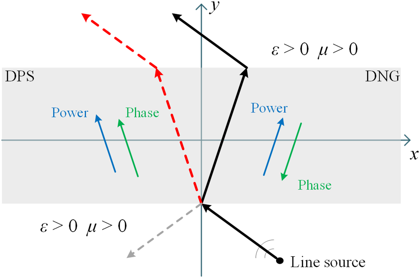
Figure 1 shows the classification of materials according to the electromagnetic parameters. In the first quadrant, the positive permeability μ and the positive permittivity ε represent a classic type of regular dielectrics. The materials in the second, third, and fourth quadrants have either negative ε or negative μ, or the both. Especially for the third quadrant, Fig. 2 graphically demonstrates the different propagation route with respect to the double-positive (DPS) and the double-negative (DNG) slabs, respectively, namely the DNG medium can make the refraction route exist in the same side of the normal as the source route.
Classification of materials with respect to ε and μ.
Schematics of DPS (x ≤ 0) and DNG (x ≥ 0) slabs.
Although the left-handed characteristics of metamaterials have shown significant research and application meanings, there is still a long road ahead. In recent years, a great number of attempts have been conducted by academic researchers and industrial engineers, particularly aiming to optimize the topology of metamaterials based on specific application purposes and working conditions. In [Reference Huang, Wen, Li and Xie18], a type of left-handed materials was proposed and analyzed by adopting the single-unit cell as depicted in Fig. 3, which consists of the ferrites to provide a negative permeability and a wire array to provide a negative permittivity. The effective regions are within the circle with the radius r 1. The region between circles with the radius r 1 and the radius r 2 is filled with a non-magnetic dielectric insulator. Then, the left-hand material has a negative pass-band for microwave frequencies with extremely small reflections and losses. It can be used widely in microwave engineering applications. In addition, an open-ended coaxial line probes with negative permittivity materials was presented in [Reference Boybay and Ramahi19]. Figure 4 graphically demonstrates the structure. The presented work showed that the sensitivity of open-ended coaxial line probes with strong implication can be effectively enhanced by utilizing a negative material layer, which is conductive for sensors to detect the delamination in ICs or cracks on surfaces covered by paint. In [Reference Gu and Zhang20], a novel topology of left-hand material was proposed and implemented as depicted in Fig. 5, where the electric field spreads along the Y-axis, the vertical magnetic field spreads along the Z-axis, and the electromagnetic wave propagates along the X-axis. The verification results show that the proposed topology can offer salient advantages of low resonant frequency, wide frequency band and simple structure. Besides, it can also achieve that the electric resonant frequency equals the magnetic resonant frequency by properly adjusting the parameters and the distance between unit cells.
Single unit cell.
Proposed open-ended coaxial line probe.
Proposed metamaterial slab. (a) Unit cell; (b) multiple-cell topology.
B) Metamaterial-based WPT
As aforementioned, the WPT technique shows a significant role to promoting the development and popularization of EVs. However, there are still inevitable technical bottlenecks for current WPT technologies, such as the low-energy efficiency, short transmission range and electromagnetic exposure, etc. The metamaterials exhibits great potentials to concentrate and enhance the magnetic flux density of the electromagnetic field by means of its left-handed characteristics. The combination between metamaterials and WPT technologies is opening a brand new research field.
1) Energy efficiency
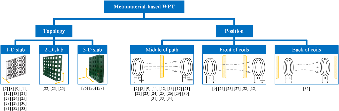
Undoubtedly, the energy efficiency is the most concerned technical performance for WPT systems, since it determines not only the output power, but also the transmission distance. To achieve the enhancement, as shown in Fig. 6, the commonly-used method is to add one or two metamaterial slabs between the transmitter and the receiver. The negative permeability can collect the leaking energy of the induced electromagnetic field, thereby increasing the mutual inductive coupling effect as well as the energy efficiency. For the optimization of the metamaterial slabs, as shown in Fig. 7, previous studies mainly focused on one-dimentional (1D) (planar), 2D, and 3D multiple-resonators topologies, as well as the relative position of metamaterial slabs against the transmitting and the receiving coils.
Exemplified WPT prototype (a) with one metamaterial slab; (b) with two metamaterial slabs.
Classification of previous studies on metamaterial-based WPT technologies.
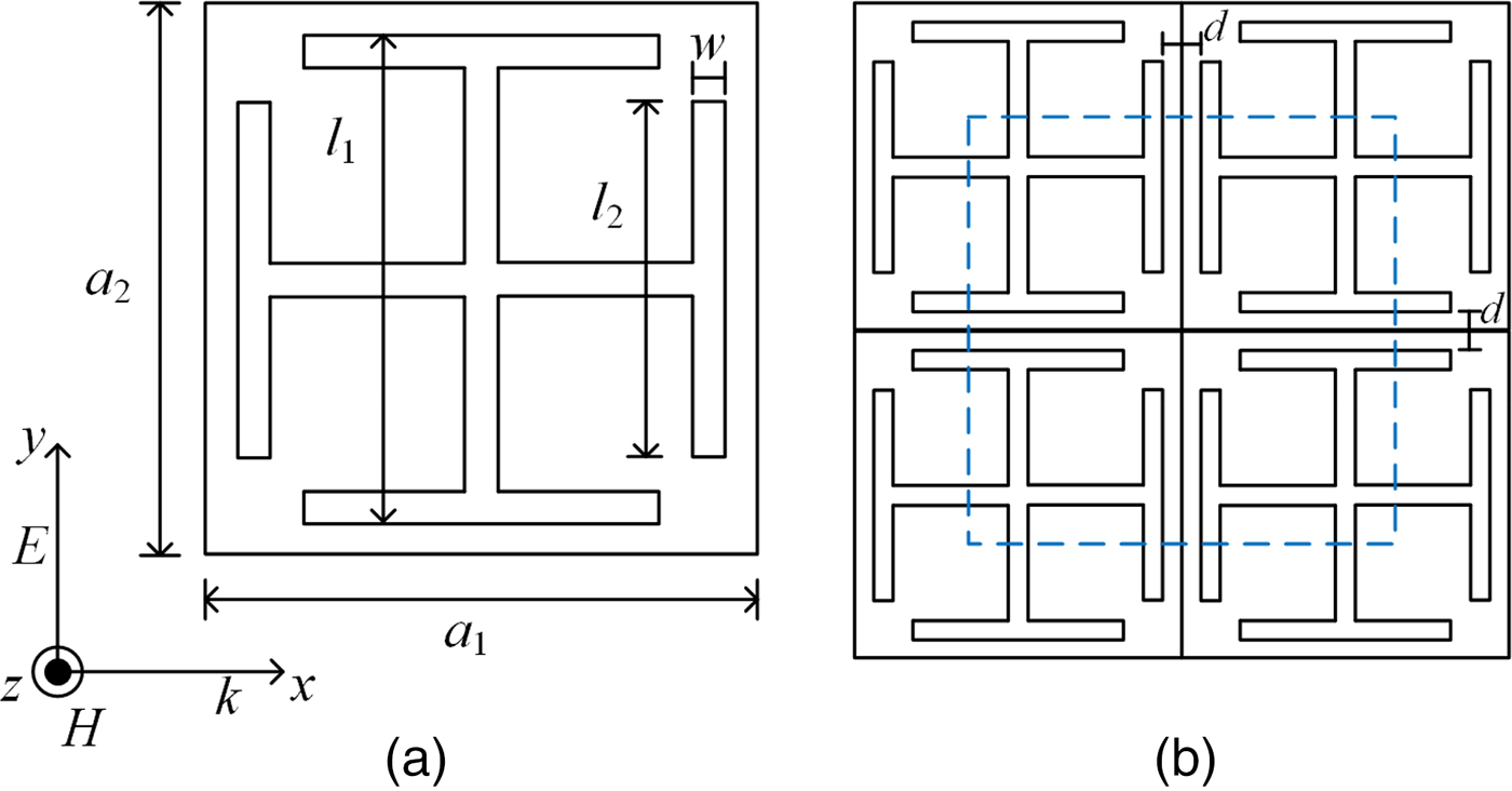
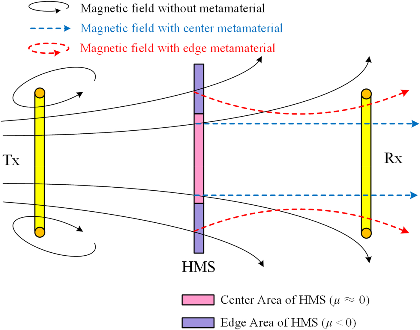
Regarding to the optimization for a single metamaterial slab, most studies focuses on the topology of multiple cells. For example, a hybrid metamaterial slab (HMS) was proposed by combining two kinds of structures of metamaterial cells with the negative and the zero permeability, aiming to improve the energy efficiency of WPT systems in [Reference Cho, Lee and Jeong21]. As depicted in Fig. 8, the HMS adopts two spiral-type patterns on a double-layered printed circuit board, which consists of the negative permeability at the edge of the slab and the zero permeability at the center of the slab. Figure 9 shows the distribution of the magnetic field induced by the proposed HMS-based WPT system. Along the transmission path between the transmitting and receiving coils, the inside magnetic field propagates straightly through the center of the proposed HMS (zero permeability), while the outside magnetic field can be concentrated into the receiving coil through the edge of the proposed HMS (negative permeability) [Reference Cho, Lee and Jeong21]. In such ways, the proposed HMS can effectively increase the energy efficiency from 8.7 to 47% for a WPT system with the transmission distance of 20 cm and the operating frequency of 6.78 MHz.
Schematics of proposed HMS. (a) Structure; (b) magnetic boundary conditions of negative-permeability metamaterials; (c) magnetic boundary condition of zero-permeability metamaterials.

Impact of proposed HMS on magnetic distribution for WPT systems.
In addition, Wang et al. developed a metamaterial slab as depicted in Fig. 10, where a double-side square spiral was taken as the unit cell of the magnetic material [Reference Wang, Teo, Nishino, Yerazunis, Barnwell and Zhang22]. Additionally, a comparative analysis was carried out among no metamaterial, planar metamaterial slab, and 2D metamaterial slab [Reference Wang and Teo23]. The corresponding experimental prototype was built to wirelessly light a 40-W bulb, which adopts the operating frequency of 27.12 MHz and the distance of 50 cm between the transmission and receiving coils. At this frequency, the effective permeability of the metamaterial is around –1. As shown in Fig. 11, the brightness of the bulb, which intuitively reflects the amount of power received, verifies the effectiveness of the metamaterial to improve the energy efficiency of WPT systems. In particular, the planar metamaterial slab can offer the optimal result by comparing with other topologies.
Two-dimensional metamaterial slab [Reference Wang, Teo, Nishino, Yerazunis, Barnwell and Zhang13].

Experimental WPT prototype. (a) Using no metamaterial slab; (b) using 3D metamaterial slab; (c) using planar double-side metamaterial slab [Reference Wang and Teo23].

Apart from the optimization of a single metamaterial slab, there are increasing studies on the spatial structure of multiple metamaterial slabs. For example, a 3D metamaterial slab was set up to explore the improvement on the transmission efficiency of WPT systems against 1D and 2D topologies [Reference Dong, Li, Cai, Yao, Ma and Tang24, Reference Li, Wang, Yao, Zhang and Tang25]. Specifically, a 6 × 6-array metamaterial slab was proposed and implemented for the magnetic resonant WPT system to light up a 15-W bulb. The corresponding geometry is given in Fig. 12, where the unit cells are periodically assembled on a 5-mm thick acrylic slab to form a 6 × 6 array. The experimental prototype was also built as depicted in Fig. 13, which consists of a source coil, a load coil connected with a bulb, the metamaterial slab placed between the transmitter and receiver, a transmitting coil and a receiving coil resonating at 6.78 MHz. Then, it compared the performance of the WPT system with 1D, 2D, and 3D metamaterial slabs by adopting the transmission distance of 0.6 m. The results show the differences of the transmission efficiency by adopting different metamaterial slabs. By observing the brightness of the bulb, the output power can be ranked as: 3D > 2-slab > 1-slab > 2D > no metamaterial slab. The corresponding efficiency values of the exemplified WPT system are also given in [Reference Li, Wang, Yao, Zhang and Tang25], which illustrates that the energy efficiency is improved by 24% when utilizing the 3D metamaterial slab.
Geometry of metamaterial slab [Reference Dong, Li, Cai, Yao, Ma and Tang24].
Exemplified 15-W WPT prototype. (a) No metamaterial slab, (b) using single metamaterial slab; (c) with two metamaterial slabs, (d) using 2D metamaterial slab; (e) using 3D metamaterial slab [Reference Li, Wang, Yao, Zhang and Tang25].

In addition, the 3D metamaterial slab can also increase the energy transmission distance. In [Reference Ranaweera, Duong, Lee and Lee26], a 3D metamaterial structure was discussed for mid-range WPT systems. The proposed structure consists of a 4 × 5 × 1-array of three-turn spiral resonators with the negative permeability at the frequency of 6.5 MHz. Both the simulated and experimental results show that the output power can be increased by 33 and 7.3% at distances of 1.0 and 1.5 m, respectively, and verify the feasibility of 3D metamaterial slabs for increasing the transmission distance of WPT systems.
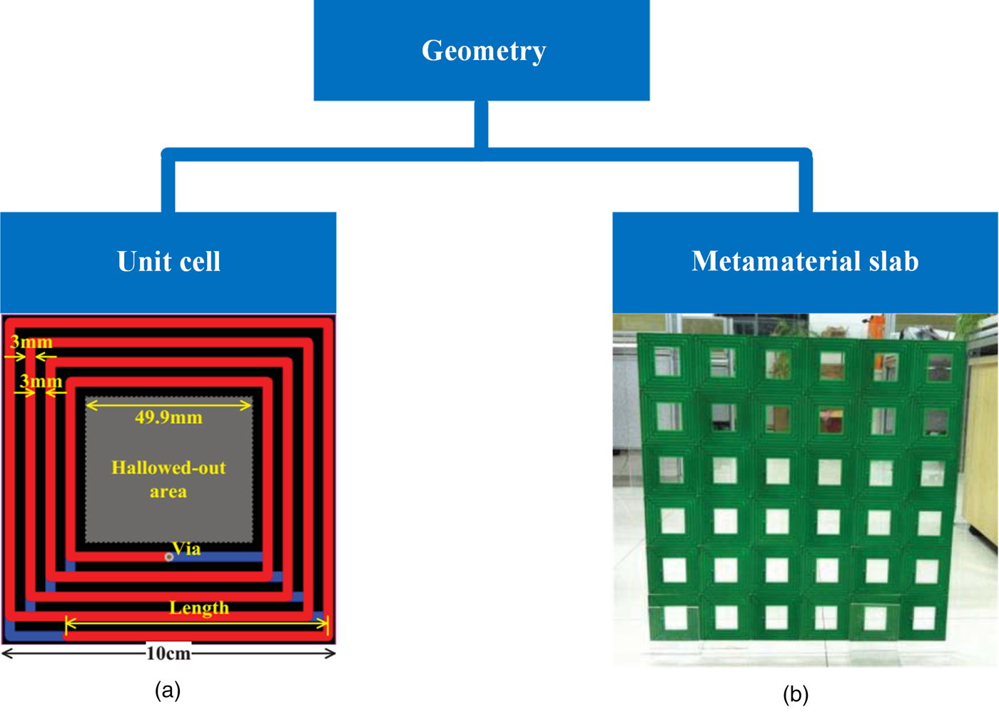
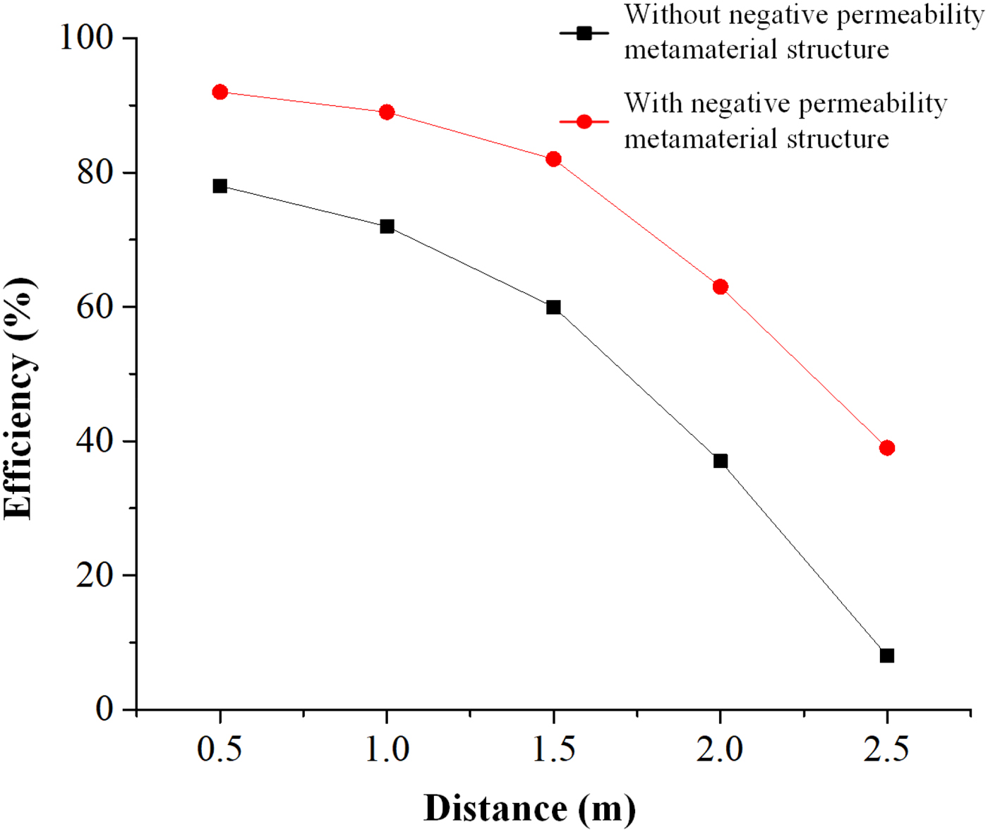
Although aforementioned studies show the advantages of 3D metamaterial slabs, it should be noted that the locating place, namely in the middle of the transmission path, significantly limit its wide applications. Accordingly, a 3D metamaterial structure was developed by periodically arranging the proposed capacitively loaded split ring resonators (CLSRRs) in the cubic dielectric surfaces [Reference Choi and Seo27], which consists of the metamaterial unit cell with 3D structure (the permeability equals –1) as shown in Fig. 14. As the most difference, Fig. 15 shows that the exemplified prototype adopts two 3D metamaterial slabs instead of one single slab locating in the middle of the transmission path like in previous studies, which locates adjacent to the source and receiving coils, respectively. This paper gives the measured efficiency of energy transmission versus the transmission distance as depicted in Fig. 16, which is used to comparatively analyze the effectiveness of metamaterials for WPT systems. The results show that the energy efficiency increases to approximately 80% at a distance of 1.5 m. More importantly, the practicability of metamaterial-based WPT technique is improved significantly.
Three-dimensional metamaterial slab. (a) Experimental prototype; (b) schematic representation of proposed CLSRR.

Exemplified WPT setup. (a) no metamaterials; (b) using metamaterials.

Measured energy efficiency with respect to transmission distance.
2) Misalignment tolerance
For WPT systems, the misalignment between the transmitter and receiver coils is one of the key factors affecting the transmission performance, and thus significantly limiting the practical applications in the static and dynamic wireless charging for electric-driving devices. In order to break through the technical bottleneck, a great number of attempts have been conducted to improve the misalignment tolerance for WPT systems.
From the perspective of the static wireless charging, the metamaterial slab is increasingly taken as an effective means to compensate the deteriorated transmission performance caused by the misalignment. The impact of the lateral and the angular misalignments on WPT systems was studied in [Reference Ranaweer, Moscoso and Lee28]. Figure 17 shows the exemplified prototype with the resonant frequency of 6.6 MHz, which consists of a source loop, a load loop, metamaterial slabs in the middle of the transmission path, a transmitting coil and a receiving coil. From the distribution of H-field magnitude as depicted in Figs 18(a) and 18(b), it illustrates that the metamaterial can enhance the coupling effect for both laterally and angularly misaligned receiving coil. The corresponding experimental results verify the effectiveness of enhancing the mutual coupling coefficient between the transmitting and the receiving coils. The comparative results also show that the metamaterial slab can effectively compensate the decrease of the energy efficiency caused by the lateral misalignment. Regarding to the angular misalignment, the energy efficiency of WPT systems is determined by the value of the angle θ. Specifically speaking, a small misalignment angle (θ < 30°) has almost no effect on the coupling coefficient. However, the efficiency decreases dramatically even if a tiny increases of θ. In such a case, the experimental results shows that the metamaterial slab can significantly improve the energy efficiency of WPT systems. Besides, the measured results at d = 100 cm illustrate the effectiveness of metamaterials even if a wide range of lateral and angular misalignments. Thus, the metamaterial exhibits great potentials to enhancing the energy efficiency of WPT systems, especially for the lateral and angular misalignments between the transmitter and the receiver coils.
Schematic of metamaterial-based WPT system with misaligned receiving coil.
Distribution of H-field. (a) Lateral misalignment of Δ = 30 cm; (b) angular misalignment of θ = 45° [Reference Ranaweer, Moscoso and Lee28].

Regarding to the dynamic wireless charging, Wang et al. designed an array of resonators for dynamic contactless charging systems [Reference Wang, Yerazunis and Teo29, Reference Yerazunis, Wang and Teo30]. By embedding the transmitting array of resonators beneath the road or the power track, the energy can be wirelessly and continuously transmitted to vehicles driving on the road. As depicted in Fig. 19, the array is formed by a series of resonators with the same resonant frequencies, where all resonators can be excited sequentially by an external power source due to the resonant coupling effect between adjacent units. Figure 20 shows that the efficiency can achieve to around 75%. In addition, the experimental prototype was also built by using the proposed planar array of resonators. The results show that the exemplified train can run continuously along the oval track by wirelessly acquiring the energy.
Schematic representation of WPT systems; (a) coil-to-coil; (b) array-to-coil.

Diagram of efficiency [Reference Wang, Yerazunis and Teo29].

3) Compacting size
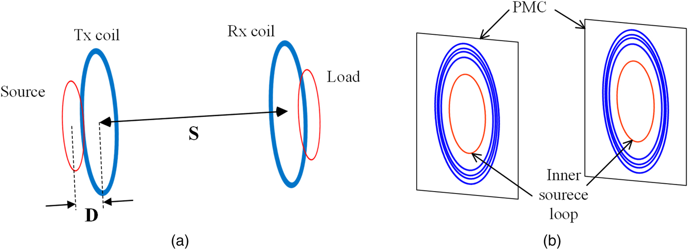
Although the metamaterial has exhibited salient advantages as aforementioned, its bulky size is still a non-ignorable technical limitation for the practical application of WPT systems [Reference Cheng, Jin, Li, Chen, Wang and Gong31–Reference Rodríguez, RamRakhyani, Schurig and Lazzi34]. Accordingly, a perfect magnetic conductor (PMC) on both side of transmitter and receiver coil was proposed for WPT systems [Reference Wu, Wang, Yerazunis and Teo35]. For the perfect electric conductor (PEC), the image current is reversed to the direction of the originating current flow, thus producing an opposing magnetic field. On the other hand, for PMC reflector, the image current possesses the same direction as the original current flow, thus strengthening the induced magnetic field. Then, these image currents can enhance the evanescent field distribution. As shown in Fig. 21(a), the proposed WPT system is built based on coupled resonant coils, where the distance equals 0.4 m. The non-resonant loop is placed inside corresponding coil by sharing the same plane. In addition, the PMC plane is placed directly behind the coil and the loop with a spacing of 0.6 cm as depicted in Fig. 21(b). In such ways, the thickness of the transmitter and receiver units decreases from 8 to 1 cm. From the verification results, it shows that the proposed PMC reflector can effectively enhance the coupling coefficient and increase the transmission efficiency from 47.86 to 71.96%. With compact size and improved efficiency, the proposed metamaterial-based WPT system is promising for many applications.
(a) WPT via magnetic resonant coupling; (b) WPT system with PMC reflectors.
III. OPPORTUNITIES
As aforementioned, the WPT technologies incorporating the metamaterial can offer an enhanced transmission performance. With increasingly application of wireless charging technologies for EVs, the study on the metamaterial-based WPT will undoubtedly attract increasing attentions from academic researchers and industrial institutions. Its salient advantages will further promote the development and application of the contactless static and dynamic charging technologies for EVs, which has been summarized as below.
-
(1) As the most important indicator, the energy efficiency can be effectively increased by utilizing the metamaterial, which is exactly the major research topic for metamaterial-based WPT technologies. Then, it exhibits great potentials to reduce the power loss of secondary energy conversion process in EV contactless charging systems. Then, the metamaterial-based WPT technique can improve the energy utilization and reduce the charging fees for end users. Meanwhile, the enhancement of the energy efficiency also means the increasing transmission power with respect to an identical transmission distance. By estimating variations of the load and adjusting the circuit, the maximum output power can be obtained to realize wireless fast charging for EVs. In such ways, a short charging time can significantly stimulate the purchase desire, thus facilitating the wide application of EVs.
-
(2) In addition, the metamaterial-based WPT can effectively increase the transmission distance, which means that the receptor can be wirelessly energized in a wide range. The extension of the charging range significantly enhances the flexibility of accessing energy. For EV contactless charging, the metamaterial-based WPT can enrich the charging style. For example, the lateral charging can be realized by means of the extended energy transmission distance, where the exciting coil can be mounted in street lights or fences instead of burying beneath the ground. In such ways, the investment of EV contactless charging systems can be reduced significantly. Accordingly, the lateral charging is undoubtedly conductive for the development of EV roadway-powering systems.
-
(3) As another salient technical advantage, the metamaterials can enhance the misalignment tolerance for WPT systems, which is extremely critical for EV contactless charging systems. Regarding park-and-charge, it reduces the requirement of parking position of EVs, that is, the battery can be still energized even if the vehicle locates arbitrarily in the allowable parking area. Regarding to move-and-charge, additionally, the effective contactless charging range can be extended significantly, which means the EV can acquire increased energy within a specified charging distance. Undoubtedly, the metamaterial-based WPT technique shows important meanings to reduce the dependence on batteries and extend the travel distance for EVs.
-
(4) Besides, the utilization of metamaterials facilitates the miniaturization of WPT systems. Accordingly, it can effectively reduce the mounting space inside vehicles so as to increase the capacity of batteries and thus extend the travel distance of EVs.
IV. CHALLENGES
The utilization of metamaterial-based WPT technologies is expected to address the technical bottleneck of current EV development and provide infinite possibilities for future applications. However, there are still non-ignorable technical challenges for the technical combination between the metamaterial-based WPT and EVs.
For EV contactless charging systems, in addition to the energy efficiency, another technical issue is to realize the high-power transmission for metamaterial-based WPT systems. However, the resonant frequency producing the left-handed characteristic is at least in the megahertz range. The current power-electronic-based switch cannot deal with a high power at such a high operating frequency, which is the biggest technical challenge of the metamaterial-based WPT technique for EV contactless charging. Besides, such a high resonant frequency used in EV charging will result in an inevitable power loss of power-electronic-based switches. Thus, the key technique for EV contactless charging systems is to achieve the negative permeability of metamaterials in the kilohertz range.
Additionally, while the metamaterial-based WPT system possesses the salient technical advantages, the metamaterial inevitably produces additional power loss. It is necessary to evaluate the dissipation and minimize the loss of metamaterials by optimizing resonant unit cells and structures. Thus, the future studies should take into account the impact of metamaterials on WPT system as aforementioned.
From previous studies, a number of attempts have been conducted to analyze and optimize the relative position of metamaterial slabs against the transmitting and the receiving coils, such as the transmission path, the front of coils and the back of coils. Apparently, it is not practical if the metamaterial slab locates in the middle of the transmission path, which inevitably deteriorates the flexibility of wireless charging for EVs, even worse than the conventional cable charging way. Thus, the future study should focus on the optimization of the mounting position of metamaterials, aiming to prevent any additional medium from existing in the transmission path between exciting coils and EVs.
Besides, it should be noted that most of existed metamaterial slabs have a bulky size. Even though it can offer remarkable improvements for wireless charging systems, the current metamaterial-based WPT technique cannot be directly utilized for EV contactless charging systems due to its unacceptable volume and weight. Especially for the receiving unit, there is no such a big space inside vehicles for bulky metamaterial slabs. Undoubtedly, a compact and miniaturized size of metamaterials is an inevitable technical requirement ahead for EV contactless charging systems. Additionally, the study on flexible metamaterials is another important topic to further improve the practicability and applicability of metamaterial-based WPT technique for EVs.
V. CONCLUSION
This paper reviewed recent researches on the metamaterial and its application to WPT technologies with emphasizes on the left-handed characteristics, the optimization of multiple-cell topology, and the impact of relative position against transmitting/receiving coils. The existed research results have shown the significant meaning of metamaterials to enhance performances of WPT systems, including the energy efficiency, transmission distance, misalignment tolerance, compacting size, and lowering frequency. For the static and dynamic contactless charging of EVs, this paper discussed about the development opportunities brought by the salient advantages of metamaterial-based WPT technologies and the technical challenges ahead. This paper aims to exhibit a big image of current research status for metamaterial-based WPT technologies, specify corresponding salient technical advantages and clarify the future studies for EV contactless charging systems.
ACKNOWLEDGEMENTS
This work was supported in part by the National Natural Science Foundation of China (Project No. 51607120), in part by the Natural Science Foundation of Tianjin China (Project No. 16JCQNJC01500), and in part by the Tianjin University PEIYANG Scholar – Reserved Academic Program (Project No. 2017XRX-0017).
 Zhen Zhang (S'11-M'13-SM'15) received the B. Eng. and M. Eng. degrees from Tianjin University, Tianjin, China, in 2004 and 2007, respectively, and the Ph.D. degree from The University of Hong Kong, Hong Kong, in 2014. He worked at IBM Research Lab supported by IBM Great Minds Program and served as a Postdoctoral Fellow at The University of Hong Kong in 2014. Currently, he is an Associate Professor in the School of Electrical and Information Engineering at Tianjin University and an Honorary Associate Professor in the Department of Electrical and Electronic Engineering at The University of Hong Kong. He has authored or co-authored more than 30 internationally refereed papers and two book chapters. His research interests include wireless power transfer, electric drives, power electronics, and distributed energies. Dr. Zhang currently serves as an associate editor of the IET Renewable Power Generation, an executive editor of the Cambridge Journal – Wireless Power Transfer, and an Editorial Board Member of the IEEE Transactions on Magnetics.
 Bowen Zhang was born in China in 1995. He received the B. Eng. degree from China University of Mining and Technology, Xuzhou, Jiangsu, China, in 2017. He is pursuing the M. Eng. degree at Tianjin University, Tianjin, China. His current research interests include wireless power transfer, metamaterials and power electronics.
 Bin Deng was born in China, in 1979. He received the M.S. and Ph.D. degrees in Electrical Engineering from Tianjin University, Tianjin, China, in 2004 and 2007, respectively. He is currently a Professor in the School of Electrical and Information Engineering, Tianjin University, Tianjin, China. His current research interests include analysis and control of nonlinear system, the dynamic of neural system, the noninvasive neural stimulation, and the analysis of neural signals.
 Xile Wei was born in China, in 1975. He received the M.S. and Ph.D. degrees in Electrical Engineering from Tianjin University, Tianjin, China, in 2004 and 2007, respectively. He is currently an Associate Professor in the School of Electrical and Information Engineering, Tianjin University, Tianjin, China. His current research interests include analysis and control of nonlinear system, the dynamic of neural system, the noninvasive neural stimulation, and the analysis of neural signals.
 Jiang Wang was born in China, in 1964. He received the B.S., M.S., and Ph.D. degrees from Tianjin University, Tianjin, China, in 1986, 1989, and 1996, respectively. He is currently a Professor with the School of Electrical and Information Engineering, Tianjin University, Tianjin, China. His current research interests include neural control engineering, bioelectromagnetics effects, and nonlinear control.


