


1. Introduction
What are the mechanical conditions that allow rock fractures to initiate and, subsequently, propagate? Further, what factors control eventual rock-fracture arrest? More specifically, what physical conditions determine how fractures select their paths? To answer these and related questions about rock fractures, we first need to be clear about the main mechanical types of rock fractures. There are only two, namely shear fractures and extension fractures. Shear fractures form by shear stresses and include all faults and some rock fractures classified as joints. Extension fractures include all tension fractures and fluid-driven fractures. The latter comprise almost all dykes, inclined sheets, sills and human-made hydraulic fractures, as well as many mineral veins and joints: in summary, all fractures where the fluid pressure is high enough to rupture the rock and form, and to drive or propagate the resulting fracture. Here the focus is on fluid-driven rock fractures, which are also referred to as hydrofractures. These are extension fractures that can be modelled as mode I (opening-mode) cracks.
The above are mostly standard definitions from structural geology/tectonics and rock physics, and have been widely used for decades (Griggs & Handin, Reference Griggs and Handin1960; Dennis, Reference Dennis1972; Jaeger & Cook, Reference Jaeger and Cook1979; Segall, Reference Segall1984; Pollard & Aydin, Reference Pollard and Aydin1988; Twiss & Moores, Reference Twiss and Moores1992). These and other definitions of rock fractures and crustal fluids used in this paper are mostly the same as used in modern textbooks (Pollard & Fletcher, Reference Pollard and Fletcher2005; Schultz, Reference Schultz2019). The main divergence in the definition of terms used in this paper concerns the concept of overpressure or driving pressure of hydrofractures. In the hydrocarbon industry, overpressure commonly indicates fluid pressure in the crust in excess of hydrostatic pressure, and that definition of the term is sometimes used in structural geology (Bons et al. Reference Bons, Elburg and Gomez-Rivas2012). This definition is well established in the hydrocarbon industry for pore-fluid pressure in rock layers and hydrocarbon reservoirs. However, it is not a very helpful definition when dealing with hydrofactures because then overpressure cannot be related to the conditions for rock rupture and hydrofracture propagation, or to their eventual dimensions, using results from fracture mechanics. To analyse rock rupture and hydrofracture propagation, overpressure must refer to the normal stress on the fracture which, for hydrofractures as defined here, is normally the minimum principal compressive stress, σ 3; that is the definition of overpressure used here. In this paper, all definitions from rock-fracture mechanics and fluid mechanics follow those given by Gudmundsson (Reference Gudmundsson2011, Reference Gudmundsson2020), all of which are widely used in earth sciences. Additionally, fault slips in a zone of high fluid pressure, as are very common, are not regarded as being related to hydrofracture/extension fracture propagation but rather as being the result of shear failure and therefore modelled as mode II or mode III (or possibly mixed-mode) cracks.
In this paper, I explore and explain the physics of fluid-driven fracture (hydrofracture) paths. The focus is on magma-driven fractures, particularly on dykes, for the simple reason that numerous well-exposed dykes have been studied in the field where they are seen as having propagated through heterogeneous and layered (anisotropic) crustal segments (Geshi et al. Reference Geshi, Kusumoto and Gudmundsson2010, Reference Geshi, Kusumoto and Gudmundsson2012; Galindo & Gudmundsson, Reference Galindo and Gudmundsson2012; Geshi & Neri, Reference Geshi and Neri2014; Drymoni et al. Reference Drymoni, Browning and Gudmundsson2020, Reference Drymoni, Browning and Gudmundsson2021; Gudmundsson, Reference Gudmundsson2020). Many dyke paths have been studied in detail vertically over hundreds of metres and laterally for kilometres, and traced for tens and, occasionally, hundreds of kilometres. In addition, the propagation of many dykes has been inferred from the migration of dyke-induced earthquake swarms and surface deformation in volcanoes during unrest periods (Peltier et al. Reference Peltier, Ferrazzini, Staudacher and Bachelery2005; Grandin et al. Reference Grandin, Jacques, Nercessian, Ayele, Doubre, Socquet, Keir, Kassim, Lemarchand and King2011; Gudmundsson et al. Reference Gudmundsson, Lecoeur, Mohajeri and Thordarson2014; Agustsdottir et al. Reference Agustsdottir, Woods, Greenfield, Green, White, Winder, Brandsdottir, Steinthorsson and Soosalu2016).
Much research has also been conducted on human-made hydraulic fractures for over 70 years in the hydrocarbon industry. These are also fluid-driven fractures and the study of these – including seismic monitoring (Shapiro, Reference Shapiro2018), cores taken through the seismic volumes to focus on the fracture types generated (Gale et al. Reference Gale, Elliott, Li and Laubach2019, Reference Gale, Elliott, Rysak, Ginn, Zhang, Myers and Laubach2021), and their propagation paths and geometries (Howard & Fast, Reference Howard and Fast1970; Warpinski & Teufel, Reference Warpinski and Teufel1987; Warpinski et al. Reference Warpinski, Lorenz, Branagan, Myal and Gall1993; Fast et al. Reference Fast, Murer and Timmer1994; Mahrer, Reference Mahrer1999; Fisher & Warpinski, Reference Fisher and Warpinski2011; Davis et al. Reference Davis, Mathias, Moss, Hustoft and Newport2012; Flewelling et al. Reference Flewelling, Tymchak and Warpinski2013; Fall et al. Reference Fall, Eichhubl, Bodnar, Laubach and Davis2015) – provides additional information on such fractures. Mineral-filled extension (opening-mode) fractures, known as mineral veins (Philipp, Reference Philipp2008, Reference Philipp2012; Bons et al. Reference Bons, Elburg and Gomez-Rivas2012), also provide information on the propagation of fluid-driven fractures, although on a much smaller scale than for dykes (Hillis, Reference Hillis, Van Rensbergen, Hillis, Maltman and Morley2003; Cobbold & Rodrigues, Reference Cobbold and Rodrigues2007). The role of chemistry (including crystal growth and dissolution rates) in the development of mineral veins has received much attention in recent years (Laubach et al. Reference Laubach, Lander, Criscenti, Anovitz, Urai, Pollyea, Hooker, Narr, Evans, Kerisit, Olson, Dewers, Fisher, Bodnar, Evans, Dove, Bonnell, Marder and Pryak-Nolte2019). However, the focus here is on the mechanical aspects of mineral-filled fracture initiation and propagation. While some mineral-filled fractures are shear fractures, field studies suggest that close to 80% of mineral veins, even inside fault zones, are extension fractures (Gudmundsson et al. Reference Gudmundsson, Berg, Lyslo and Skurtveit2001, Reference Gudmundsson, Fjeldskaar and Brenner2002; Philipp, Reference Philipp2008, Reference Philipp2012). Most mineral veins may therefore be regarded as extension (opening-mode) fractures whose attitude (strike and dip) was perpendicular to the local orientation of σ 3 at the time of vein formation. However, many veins are confined to single layers (stratabound/layerbound), that is, arrested in vertical sections, and the mechanics of arrest and its implication for the vein-propagation-path selection are not fully understood (Gudmundsson, Reference Gudmundsson2011).
In conventional hydraulic fracturing in the oil industry, the likely generalized propagation path of a fracture injected laterally into a single mechanical unit/layer has often been forecast based on current stress data and other information (Valko & Economides, Reference Valko and Economides1995; Yew & Weng, Reference Yew and Weng2014; Shapiro, Reference Shapiro2018). In fact, small-scale hydraulic fracturing is used to determine the orientation of σ 3 in hydraulic fracturing stress measurements (Amadei & Stephansson, Reference Amadei and Stephansson1997; Zoback, Reference Zoback2007; Zang & Stephansson, Reference Zang and Stephansson2014). In unconventional, primarily vertical, propagation of hydraulic fractures, such as used in the extraction of gas from shales, the forecast paths are much less reliable, with the fractures commonly becoming deflected laterally along contacts to form water sills or deflected into faults, or otherwise following non-predicted paths (Warpinski & Teufel, Reference Warpinski and Teufel1987: Fisher & Warpinski, Reference Fisher and Warpinski2011; Davis et al. Reference Davis, Mathias, Moss, Hustoft and Newport2012; Fisher, Reference Fisher2014). As for natural hydrofractures, the generalized attitude (strike and dip) of dykes has for a long time been known to be crudely perpendicular to the regional direction of σ 3 at the time of dyke emplacement (Anderson, Reference Anderson1942). However, despite the high-density instrumentation (seismic and geodetic networks) in many volcanoes and volcanic zones today, no detailed dyke path in an active volcano has ever been successfully forecast (Gudmundsson, Reference Gudmundsson2020). Because a feeder dyke must reach the surface to erupt, and since volcanoes and volcanic zones are layered and faulted, the propagation path up through the layers on the way to the surface is of the greatest interest. Vertical and inclined propagation paths of hydrofractures through layered and faulted rocks are therefore the main focus of this paper.
More specifically, the principal aim of this paper is to answer the question: how does a fluid-driven rock fracture (a hydrofracture) select its path when propagating up through a layered and faulted crustal segment? As is explained, each hydrofracture theoretically has an infinite number of potential propagation paths to select from. The question is therefore: which path does it select and why? Here, for the first time, Hamilton’s principle of least action is applied to hydrofractures with a view of forecasting their likely paths through layered rocks. Additionally, using energy considerations, I provide a quantitative analysis of the potential of existing faults to act as parts of hydrofracture paths. For these purposes, the paper begins with a review of relevant field observations of hydrofracture paths. This is followed by a brief discussion of the conditions for hydrofracture initiation. The physics of hydrofracture-path selection in layered rocks, the main theme of this paper, is then discussed in considerable detail, including the potential effects of faults to provide parts of the paths. A discussion of the implications of the theory presented here, for the understanding of the physics of hydrofracture propagation with application to dykes reaching the surface to supply magma to volcanic eruptions, is also included.
2. Field observations
Observations of natural fluid-driven fractures (hydrofractures) in the field are primarily of sheet intrusions and mineral veins. In addition, there are detailed data on human-made hydraulic fractures used in the hydrocarbon and geothermal industries. This section provides a short overview of these aspects of fluid-driven fractures, with a focus on the natural fractures. Much more detailed field descriptions of natural hydrofractures are provided by Segall (Reference Segall1984), Pollard & Aydin (Reference Pollard and Aydin1988), Hillis (Reference Hillis, Van Rensbergen, Hillis, Maltman and Morley2003), Cobbold & Rodrigues (Reference Cobbold and Rodrigues2007), Philipp (Reference Philipp2008, Reference Philipp2012), Gudmundsson (Reference Gudmundsson2011, Reference Gudmundsson2020), Geshi et al. (Reference Geshi, Kusumoto and Gudmundsson2010, Reference Geshi, Kusumoto and Gudmundsson2012), Bons et al. (Reference Bons, Elburg and Gomez-Rivas2012), Galindo & Gudmundsson (Reference Galindo and Gudmundsson2012), Kusumoto et al. (Reference Kusumoto, Geshi and Gudmundsson2013), Kusumoto & Gudmundsson (Reference Kusumoto and Gudmundsson2014), Fall et al. (Reference Fall, Eichhubl, Bodnar, Laubach and Davis2015), Tibaldi (Reference Tibaldi2015), Gale et al. (Reference Gale, Elliott, Li and Laubach2019) and Laubach et al. (Reference Laubach, Lander, Criscenti, Anovitz, Urai, Pollyea, Hooker, Narr, Evans, Kerisit, Olson, Dewers, Fisher, Bodnar, Evans, Dove, Bonnell, Marder and Pryak-Nolte2019).
The largest exposures of natural hydrofractures are those of dykes. Some dykes have continuous vertical exposures of hundreds of metres (Geshi et al. Reference Geshi, Kusumoto and Gudmundsson2010, Reference Geshi, Kusumoto and Gudmundsson2012) and can be traced laterally for many kilometres (Anderson, Reference Anderson1942; Gudmundsson, Reference Gudmundsson1983, Reference Gudmundsson2020; Pollard & Fletcher, Reference Pollard and Fletcher2005; Geshi & Neri, Reference Geshi and Neri2014) although the lateral exposures may not be continuous; the same applies to sills (Fig. 1). By contrast, the exposures of inclined (cone) sheets, both in vertical and in horizontal sections, are normally much more limited (Fig. 2) for the simple reason that these are much smaller structures than regional dykes (Galindo & Gudmundsson, Reference Galindo and Gudmundsson2012; Kusumoto et al. Reference Kusumoto, Geshi and Gudmundsson2013; Tibaldi, Reference Tibaldi2015; Gudmundsson, Reference Gudmundsson2020).
Composite dyke in East Iceland. Looking north, the thickness of the rhyolite is 13 m, the western basalt 7.5 m and the eastern basalt 5 m, bringing the total thickness to 25.5 m. The dyke can be traced laterally for about 14 km, its strike changing from N20° E here to N14° E towards its northern end. The dyke extends to the top of the 700-m-high mountain on the other side of the fjord (seen here), but the basaltic parts drop out in the middle part of the mountain so that at the top the dyke is purely acid and 35 m thick. A 120-m-thick multiple sill dissects the dyke, and is therefore younger than the dyke.

Inclined sheets and (above) lava flows in a fossil central volcano in West Iceland. Also seen is alteration due to circulation of geothermal water while the central volcano was active, some 2.8 Ma ago. The thicknesses of most of the inclined sheets are 0.5–1 m.

The dimensions of mineral veins are mostly of the order of tens of centimetres to a few metres (Philipp Reference Philipp2008, Reference Philipp2012; Gudmundsson, Reference Gudmundsson2011; Bons et al. Reference Bons, Elburg and Gomez-Rivas2012), but some reach many metres or more in length or strike dimension (Fig. 3). Their height or dip dimension can also reach several metres but, more commonly in layered rocks such as sedimentary piles, the dip dimensions are tens of centimetres to a few metres, with the veins commonly being stratabound (Fig. 4). In contrasts to dykes (and sills and inclined sheets), mineral veins commonly form dense networks where many of the hydrofractures were active, that is, transporting fluids, at the same time (Fig. 5).
Large mineral veins (of calcite) in limestone in SW England. The measuring tape is 8 m long.

Stratabound (layerbound) calcite veins in limestone in SW England. Mineral veins in sedimentary basins such as here in the Bristol Channel are commonly arrested at contacts between mechanically dissimilar layers. Here the veins are arrested at contacts between comparatively stiff limestone layers and comparatively compliant (at the time of vein formation) shale layers (Philipp, Reference Philipp2012).

Dense network of mineral veins (of various minerals) in the Husavik–Flatey Fault, a transform fault zone in North Iceland. About 80% of the veins are extension fractures. The veins are exposed here at a depth of about 1500 m below the original surface of the lava pile that the fault dissects (Gudmundsson et al. Reference Gudmundsson, Berg, Lyslo and Skurtveit2001, Reference Gudmundsson, Fjeldskaar and Brenner2002).

For understanding hydrofracture propagation paths, and for modelling purposes, it is of fundamental importance to determine to which mechanical type of fracture most hydrofractures belong. Cross-cutting relationships (Fig. 5) as well as orientation of fibres in the veins (Philipp, Reference Philipp2008, Reference Philipp2012) indicate that most mineral veins are extension fractures, even inside fault zones (Fig. 5). For dykes and inclined sheets, the type of fracture is also easiest to determine in the field from cross-cutting relationships, either between dykes and sheets, or between these intrusions and the layers that they dissect (mostly lava flows or pyroclastic layers).
On a regional scale, the cross-cutting relationships between dykes and the lava flows (and pyroclastic layers) that they dissect provide ample evidence that most dykes are extension (opening-mode) fractures. Such cross-cutting relationships in vertical cross-sections demonstrate that the dykes do not occupy dip-slip faults (Fig. 6). When the dykes are followed along their length (the strike dimension), similar cross-cutting relationships show that the dykes do not occupy strike-slip faults. On a local scale, cross-cutting relationships and the absence of slickensides further demonstrate that most dykes and inclined sheets are extension fractures. In some cases the cross-cutting relationship includes several dykes and inclined sheets, in which case the evidence for their being extension fractures is very clear (Fig. 7).
Regional basaltic dykes dissecting a pile of mostly basaltic lava flows in SE Iceland. The dykes dissect the lava flows at right angles. The absence of vertical displacements parallel with the dykes suggests that the dykes are extension fractures. Ten dykes are indicated, and the sub-horizontal arrows indicate how the dip of the lava pile increases with depth in the crust. The floor of the valley where the photo is taken is at about 2000 m depth below the initial top of the lava pile.

Cross-cutting basaltic dykes and inclined sheets in South Iceland. The relationships indicate that there is no displacement parallel with any of the sheet intrusions, which should therefore be interpreted as extension fractures (and modelled as mode I cracks). The host rock is lake sediment. The length of the hammer is about 30 cm.

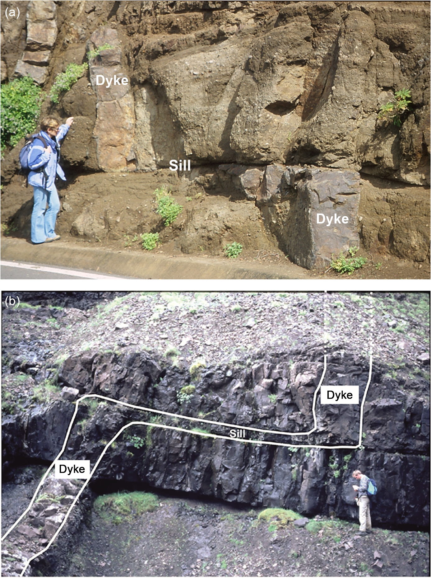
Many regional dyke paths in vertical sections are comparatively straight (Fig. 6). This applies particularly to dykes propagating up through a basaltic lava pile where all the mechanical properties of the flows are similar and there are no thick layers of compliant (soft) scoria, soil or pyroclastics in-between the lava flows. When such layers exist, or when the lava flows are of widely different mechanical properties and the pile contains very stiff sills as well as lava flows, then the dyke paths tend to become much more irregular. In particular, in a pile of layers with contrasting mechanical properties – layers with widely different Young’s moduli – the propagation paths of dykes and inclined sheets (as seen in vertical sections) commonly show abrupt changes in attitude, resulting in a zig-zag geometry (Fig. 8). Where the attitude of the path changes abruptly (e.g. where a vertical dyke temporarily deflects into a sill and then back into a dyke), the thickness normally also changes. In particular, the sill part of the path may be much thinner than the nearby dyke parts (Fig. 8).
Zig-zag geometry of dykes. (a) Basaltic dyke becomes deflected into a thin sill along a contact between pyroclastic layers in Tenerife (Canary Islands). The lower dyke segment is 0.43 m thick, strikes N12° E and dips 87° W, whereas the upper segment is 0.46 m thick, strikes N1° E and dips 89° W. The dyke strike therefore changes by c. 11° on crossing the contact, whereas the dyke thickness remains similar. However, at the contact itself the dyke changes into a sill with a thickness of as little as 2 cm for a lateral distance of about 3.4 m. (b) Dyke changing into a sill along part of its path in West Iceland. The change occurs at the contact between mechanically dissimilar rocks, the contact itself being composed of comparatively soft scoria (along which the sill is deflected), whereas the layer above (the one on top of the present sill) is stiff basaltic lava flow. The horizontal length of the sill is c. 8 m. The vertical dyke segments are c. 0.8 m thick.
Abrupt changes in the propagation-path attitude are also common in mineral veins. This happens particularly when the veins meet existing discontinuities with little or no tensile strength, such as active or recently active faults (Fig. 9). As is the case for dykes, the veins are commonly much thinner in the part of the propagation path that uses the fault.
Gypsum veins deflect into a curving (listric) normal fault for parts of their paths in the Bristol Channel in SW England. The veins used the fault as paths presumably because the tensile strength of the fault at the time of vein formation was zero (assuming that the fault had recently slipped or formed). The veins are notably thinner in the parts of the paths that are along the fault because they are there no longer perpendicular to the minimum principal compressive stress σ 3, but rather to a normal stress σ n on the fault plane (and also because their paths within the faults are very short). The host rock is red mudstone (Philipp, Reference Philipp2008).

Dykes are generally segmented (Fig. 10a). The segmentation is partly because the dykes propagate as individual so-called fingers and at different rates. For feeder dykes, the first finger that reaches the surface initiates the eruption (Fig. 10b). Segmentation is in fact a universal feature of rock fractures; mineral veins are therefore commonly seen as segmented, even when their exposed lengths are of the order of metres or less (Fig. 11).
Segmented dykes. (a) Six segments of a 5-m-thick basaltic regional dyke in NW Iceland. This dyke is more resistant to erosion than the host rock, and therefore stands as segmented ridge above the surroundings. (b) Schematic illustration of a propagating segmented dyke. The first dyke finger to reach the surface initiates the resulting fissure eruption. The first segments at the surface are commonly short (tens of metres), but they commonly propagate laterally at the surface and may eventually link up into larger fissure segments (Gudmundsson, Reference Gudmundsson2020).

Segmented mineral veins in vertical and lateral sections in the Bristol Channel in SW England. (a) Segmented calcite veins in a vertical section through (mostly) shale layers and (at the top) limestone layers. The length of the measuring tape is 1 m. (b) Segmented calcite vein, with an en échelon arrangement, in a lateral section in limestone.

Most hydrofracture segments become vertically arrested and commonly stratabound (Fig. 12). The fracture tip is most commonly arrested at a contact between mechanically dissimilar layers, or just below the contact between such layers. Mechanically dissimilar layers include, for example, limestone (stiff) and shale (often compliant during vein formation) layers in sedimentary basins. Many mineral veins are seen arrested at contacts between limestone and shale layers (Fig. 12a, b). Most dyke segments that are seen to end vertically do not reach the surface, but instead become arrested. While the arrested tips are commonly exactly at the contact between mechanically dissimilar layers, there are also cases where the dykes become arrested just below the contact of layers with contrasting mechanical properties, that is, when the layer above the contact is much stiffer (has a much higher Young’s modulus) than the layer below the contact and hosting the top part of the dyke (Fig. 12c, d; Forbes Inskip et al. Reference Forbes Inskip, Browning, Meredith and Gudmundsson2020).
Arrested hydrofractures, mineral veins and dykes. (a) Calcite vein arrested at contacts between shale and limestone layers. (b) Hydrofracture arrested, and forming a T-shaped fracture, at the contact between a very thin shale layer (indicated) and limestone layers. The fractures in (a) and (b) are in the Bristol Channel, SW England. (c) Arrested dyke at some distance below the contact between a basaltic lava flow and a pyroclastic layer. The thickness of the basaltic dyke gradually decreases from 25 cm at the bottom of the figure to 2 cm at the dyke tip. Next to the dyke the host rock is baked. (d) A vertically propagating basaltic dyke becomes arrested on meeting a gently dipping stiff intrusive sheet, marked as a stiff layer. View NNE, the maximum thickness of the dyke is about 0.8 m. The basaltic dykes in (c) and (d) are in Tenerife, Canary Islands.

Studies of human-made hydraulic fractures yield similar results regarding propagation and arrest as those for natural hydrofractures. Propagating hydraulic fractures, used in the hydrocarbon and geothermal industries to increase the permeability of reservoirs, generate earthquake swarms (Shapiro, Reference Shapiro2018). The swarms are mostly of microseismicity and their propagation paths can be monitored (Fisher & Warpinski, Reference Fisher and Warpinski2011; Davis et al. Reference Davis, Mathias, Moss, Hustoft and Newport2012; Flewelling et al. Reference Flewelling, Tymchak and Warpinski2013; Fisher, Reference Fisher2014). It should be noted that the microseismicity associated with hydrofracture propagation in general (including dykes) is partly attributable to fault slip in the process zone ahead of the propagating fracture tip, and partly to fault slip in the walls of the fracture (Gudmundsson, Reference Gudmundsson2011, Reference Gudmundsson2020; Geshi & Neri, Reference Geshi and Neri2014; Agustsdottir et al. Reference Agustsdottir, Woods, Greenfield, Green, White, Winder, Brandsdottir, Steinthorsson and Soosalu2016; Shapiro, Reference Shapiro2018). Close to the surface, fractures may be induced by a propagating dyke even if the dyke itself does not reach the surface (Al Shehri & Gudmundsson, Reference Al Shehri and Gudmundsson2018; Bazargan & Gudmundsson, Reference Bazargan and Gudmundsson2019; Gudmundsson, Reference Gudmundsson2020).
In conventional hydraulic fracturing the fracture that is injected laterally into a layer from a vertical well is assumed to be arrested at the top and bottom of that layer. The aim is therefore to confine the hydraulic fracture to the target layer, that is, the layer or unit containing oil or gas. The fracture should not propagate much into the layers above and below the target layer (Howard & Fast, Reference Howard and Fast1970: Valko & Economides, Reference Valko and Economides1995; Yew & Weng, Reference Yew and Weng2014; Shapiro, Reference Shapiro2018). The generalized propagation path of such lateral hydraulic fractures can often be forecast based on information such as the mechanical properties of the target layer in relation to those of the adjacent layers and that of the current stress fields. In unconventional hydraulic fracturing, developed in the past decades, the fractures are injected vertically into the rock layers from a horizontal well (Wu, Reference Wu2017; Shapiro, Reference Shapiro2018). This technique has been extensively used for getting gas out of shales (gas shales) and is now well developed. The (mostly) vertical hydraulic fractures are mechanically very similar to vertical dykes. In particular, the dip dimension or height of some hydraulic fractures exceeds 1 km (Davis et al. Reference Davis, Mathias, Moss, Hustoft and Newport2012), although most are much shorter (Fisher & Warpinski, Reference Fisher and Warpinski2011; Fisher, Reference Fisher2014), and may therefore reach dip dimensions similar to those of many radial dykes and inclined sheets injected from shallow magma chambers (Gudmundsson, Reference Gudmundsson2020).
Studies of thousands of hydraulic fractures show that their propagation paths are commonly complex and similar to those of dykes. Microseismic studies suggest that vertical hydraulic fractures commonly deflect into discontinuities such as faults and contacts, particularly at shallow depths (Fisher & Warpinski, Reference Fisher and Warpinski2011; Flewelling et al. Reference Flewelling, Tymchak and Warpinski2013). While deflection of vertical hydraulic fractures into horizontal water-sills can occur at any depth in the sedimentary basins, such a deflection is particularly common at crustal depths of less than 700–800 m (Fisher, Reference Fisher2014). Hydraulic fractures have also been observed to deflect into faults, using the faults as part of their propagation paths (Davis et al. Reference Davis, Mathias, Moss, Hustoft and Newport2012; Lacazette & Geiser, Reference Lacazette and Geiser2013), as discussed further in Section 6.c.
Following hydraulic fracture experiments, many such fractures have been studied in the subsurface in excavated sections. These studies show that the geometric features of hydraulic fractures are similar to those observed of dykes and, on a much smaller scale, mineral veins. Some hydraulic fractures, or fracture segments, are seen to be arrested at contacts between mechanically dissimilar layers, while others become deflected into water-sills (e.g. Fisher & Warpinski, Reference Fisher and Warpinski2011; Fisher, Reference Fisher2014). Clearly, the three principal mechanisms of the arrest and deflection of extension (opening-mode) fractures (mode I cracks), namely Cook–Gordon delamination, stress barriers and elastic mismatch (Gudmundsson, Reference Gudmundsson2011, Reference Gudmundsson2020), all operate on hydraulic fractures in the same way as they operate on mineral veins and dykes.
3. Fracture initiation
When the following condition is satisfied, a fluid-filled source or reservoir will rupture and inject a hydrofracture:
 $${p_{{l}}} + {p_{{e}}} = {\sigma _3} + {T_0}$$
where pl
is the magmatic pressure in the source or reservoir when the reservoir is in mechanical equilibrium with the host rock (neither expanding nor contracting), that is, before any excess pressure pe
is generated in the reservoir; pe
is the excess fluid pressure in the reservoir at the time of rupture and hydrofracture initiation; σ
3 is the minimum compressive (maximum tensile) principal stress; and ${T_0}$
is the local in situ tensile strength at the rupture site. For equilibrium, p
l must be equal in magnitude to the lithostatic stress or overburden pressure at the source/reservoir boundary. Compressive stress is considered positive and tensile stress negative. The excess fluid pressure is the pressure in excess of the lithostatic stress. Lithostatic refers to an isotropic (hydrostatic or spherical) state of stress (meaning that all the principal stresses are equal) where the stress magnitude increases proportionally with depth in the crust (or lithosphere). The rate of increase of the lithostatic stress magnitude with depth is determined by the density of the crustal/lithospheric rocks (Gudmundsson, Reference Gudmundsson2011). When the fluid-filled source is in lithostatic or mechanical equilibrium with its host rock, then pe
= 0 (there is no excess pressure) and the state of stress in the roof (and elsewhere at the boundary) of the source is such that σ
1 = σ
2 = σ
3 = p
l. This means that all the principal stresses are equal (isotropic state of stress) and equal to the lithostatic stress or overburden pressure, which (because of lithostatic equilibrium) must also be equal to the fluid pressure inside the source. The pressure in the source then entirely balances the stresses on it, implying that the source is neither expanding nor contracting (shrinking). For example, most active magma chambers are presumably in the state of lithostatic or mechanical equilibrium when there is neither inflation or deflation occurring in the associated volcano (Gudmundsson, Reference Gudmundsson2020). Equation (1) is sometimes given as pt
= σ
3 + T
0, where pt
is the total fluid pressure in the source at the time of rupture (equal to p
l + pe
in Equation (1)), an equation that is easily derived from Griffith’s theory of fracture (Jaeger & Cook, Reference Jaeger and Cook1979).
${T_0}$
is the local in situ tensile strength at the rupture site. For equilibrium, p
l must be equal in magnitude to the lithostatic stress or overburden pressure at the source/reservoir boundary. Compressive stress is considered positive and tensile stress negative. The excess fluid pressure is the pressure in excess of the lithostatic stress. Lithostatic refers to an isotropic (hydrostatic or spherical) state of stress (meaning that all the principal stresses are equal) where the stress magnitude increases proportionally with depth in the crust (or lithosphere). The rate of increase of the lithostatic stress magnitude with depth is determined by the density of the crustal/lithospheric rocks (Gudmundsson, Reference Gudmundsson2011). When the fluid-filled source is in lithostatic or mechanical equilibrium with its host rock, then pe
= 0 (there is no excess pressure) and the state of stress in the roof (and elsewhere at the boundary) of the source is such that σ
1 = σ
2 = σ
3 = p
l. This means that all the principal stresses are equal (isotropic state of stress) and equal to the lithostatic stress or overburden pressure, which (because of lithostatic equilibrium) must also be equal to the fluid pressure inside the source. The pressure in the source then entirely balances the stresses on it, implying that the source is neither expanding nor contracting (shrinking). For example, most active magma chambers are presumably in the state of lithostatic or mechanical equilibrium when there is neither inflation or deflation occurring in the associated volcano (Gudmundsson, Reference Gudmundsson2020). Equation (1) is sometimes given as pt
= σ
3 + T
0, where pt
is the total fluid pressure in the source at the time of rupture (equal to p
l + pe
in Equation (1)), an equation that is easily derived from Griffith’s theory of fracture (Jaeger & Cook, Reference Jaeger and Cook1979).
The conditions of Equation (1) can be reached by increasing pe by adding fluid to the source and/or by decreasing σ 3 through regional extension (such as at divergent plate boundaries). These conditions are well known and already implied in Anderson’s (Reference Anderson1942) models on dyke formation (Section 6.2). When the source receives an additional fluid, then the source will no longer be in lithostatic/mechanical equilibrium with the host rock. This is well established in the case of shallow magma chambers that, on receiving new magma, enter a period of unrest. Additional fluid makes the excess pressure positive (pe > 0), and increasingly so as more new fluid is received by the source. Tensile stress concentration around the source as a result of positive pe also reduces σ 3 (so that the state of stress is no longer lithostatic). For a shallow magma chamber, the increase in pe would result in inflation. Eventually, if the condition of Equation (1) is reached, either as fluid is added to the source or the source is subject to regional extension, the source boundary (the roof for a sill-like source as assumed here) ruptures and a hydrofracture (a dyke or an inclined sheet in the case of a magma chamber) is injected (Gudmundsson, Reference Gudmundsson2020).
As indicated, we assume here that the source/reservoir is sill-like, that is, penny-shaped or an oblate ellipsoid. We also assume that the lateral dimensions of the source are large in relation to the opening of the hydrofracture. The local stress conditions around a well (a drill hole of a circular horizontal cross-section), and the fact that its lateral dimension in relation to the opening of the hydraulic fracture is not as large as typical for the sources of natural hydrofactures, mean that the conditions of Equation (1) do not apply to the initiation of human-made hydraulic fractures (Gudmundsson, Reference Gudmundsson2011). Equation (1) implies that when the excess pressure pe in the source decreases, so that pe → 0, the opening of the fracture at the contact with the source/reservoir closes. This applies generally to water-driven fractures (e.g. hydrothermal/geothermal and human-made), and to fractures driven by gas and low-viscosity magmas, but less so to fractures driven open by high-viscosity magmas. It is in fact well known that many acid dykes, particularly those that become arrested (i.e. non-feeders), stay open at their contacts with the source chamber when their propagation paths come to an end (Fig. 13).
(a) Exceptionally well exposed fossil magma chambers, like this one here, commonly show part of the roof where many (here felsic) dykes can be seen cutting the roof. (b) In addition to the roof, parts of the wall of the fossil chamber (now a felsic pluton) are seen and indicated. The pluton is made of granophyre and is hosted by a pile of basaltic lava flows in SE Iceland. The floor of the valley in (a) is at 2000 m below the initial top of the lava pile (Gudmundsson, Reference Gudmundsson2020).

When using fracture-mechanics theory, the condition for hydrofracture initiation at its source is normally formulated in terms of toughness, which is a measure of the material (here, rock) resistance to fracture. The two closely related toughness measures used are material toughness and fracture toughness, which may be briefly defined as follows (Gudmundsson, Reference Gudmundsson2011).
Material toughness is a measure of the energy absorbed in a material per unit area of fracture or crack in that material, and is also referred to as the critical strain energy release rate. Material toughness is measured in units of J m−2, energy (work) per unit area, or as N m−1, that is, as force per unit length of crack. When the latter unit is used, material toughness is sometimes referred to as crack extension force. The energy release rate of a material is normally denoted G and its critical value, the material toughness, by G c. Material toughness G c is therefore the critical energy release rate needed for a crack to propagate.
Fracture toughness, the critical stress intensity factor for a fracture to propagate, is measured in units of N m−3/2 or Pa m1/2 (normally given in MPa m1/2), and is denoted K c. Fracture toughness increases with increasing volume of material at the fracture tip that deforms plastically and/or through microcracking. The energy release rate and stress intensity, and therefore material toughness and fracture toughness, are related but provide different measures of the resistance to fracture of the material and have different units. The energy release rate G measures the energy per unit area of crack extension, whereas the stress intensity factor K measures the magnitude (intensity) of the stress field close to the crack tip.
In terms of toughness, the conditions for hydrofracture initiation from its source (Equation (1)) can be presented in various forms, for example (Gudmundsson, Reference Gudmundsson2011; Kusumoto et al. Reference Kusumoto, Geshi and Gudmundsson2013):
 $${p_{{e}}} = {{{K_{{{Ic}}}}} \over {{{({{\pi}}{ a})}^{1/2}}}}$$
where KIc is the fracture toughness for an extension (mode I) fracture and a is the dip dimension (height) of the hydrofracture. When the material toughness GIc for a mode I crack is used instead of the fracture toughness, then the condition for hydrofracture initiation becomes:
 $${p_{{e}}} = {\left( {{{E{G_{{{Ic}}}}} \over {\pi \left( {1 - {\nu ^2}} \right)a}}} \right)^{1/2}}$$
where E is Young’s modulus and ν is Poisson’s ratio of the rock. Equation (3) is for plane-strain conditions, which are most suitable when dealing with hydrofractures that are hosted by crustal segments or layers/units where all the dimensions are similar, or the thickness (dip dimension) is somewhat greater than the other dimensions. When the crustal segments/layers/units have large lateral dimensions in relation to their thickness, then plane-stress conditions apply; in this case, the factor (1 − ν 2) is omitted.
Equations (2) and (3) indicate that the excess fluid pressure in the source needed for hydrofracture initiation is inversely proportional to the dip dimension of the flaw from which the fracture initiates (as a result of stress concentrations). On the scale of dykes injected from shallow magma chambers (Fig. 13), the flaws are mostly joints, and in igneous rocks primarily columnar (cooling) joints (Fig. 14). The dimensions of such joints are from tens of centimetres to 10 m or more, which is therefore the minimum size of a in these equations.
Dyke, c. 2 m thick, using existing cooling (columnar) joints as part of its path through a gabbro body. The exposure is a part of the outermost part of a fossil magma chamber (now a gabbro pluton) and located some 2000 m below the original top of the associated central volcano. Dykes and inclined sheets commonly use favourably oriented joints as parts of their paths. The joints are extension fractures.

When the hydrofracture begins to propagate up into the roof and away from the contact with its source (Figs 13, 14), buoyancy contributes to the driving pressure, which then becomes the overpressure p o defined as:
 $${p_{{o}}} = {p_{{e}}} + \left( {{\rho _{{r}}} - {\rho _{{f}}}} \right)gh + {\sigma _{{d}}}$$
where ρr is the average host-rock density, ρf is the average fluid density, g is the acceleration due to gravity, h is the dip dimension of the hydrofracture and σd is the differential stress (the difference between the maximum and the minimum principal stress) in the host rock where the hydrofracture (such as a dyke or a mineral vein) is studied in the field. The buoyancy term is because of the difference in density between the host rock and the hydrofracture fluid. The buoyancy term can be positive (average fluid density less than average rock density up to the point of interest along the hydrofracture), zero or neutral (average rock and fluid density the same) or negative (average rock density less than average fluid density).
For groundwater and geothermal water, the buoyancy term is always positive and reaches the order of mega-pascals once the hydrofracture dip dimension or height attains 100 m or more. Note that few individual mineral veins reach this height (Figs 3, 4), but the fluid path does so as part of a network of interconnected hydrofractures or veins (Fig. 5). For acid and intermediate magmas, the buoyancy is mostly positive but may be zero or somewhat negative in the very shallow crust (the uppermost 1–2 km) for intermediate magmas (typical densities of andesite are 2450–2500 kg m−3 and of shallow crustal layers 2300–2500 kg m−3; Gudmundsson, Reference Gudmundsson2020). However, mafic magmas have common densities of 2650–2800 kg m−3 so the buoyancy is almost always negative in the uppermost part of the crust for such magmas, but zero and then positive in deeper crustal levels. Since the density difference is generally much smaller (positive or negative) between magmas and crustal rocks than between water and crustal rocks, the buoyancy pressure effects reach the order of mega-pascals only when the height or dip dimension of the propagating dyke reaches 1000 m or more.
Because it is not only fluid excess pressure pe in the source, but also fluid overpressure p o where buoyancy comes into play (Equation (4)), that drives hydrofractures, the conditions for hydrofracture propagation (once the fracture has initiated) can be formulated in terms of fracture mechanics criteria as:
 $${p_{{o}}} = {{{K_{{{Ic}}}}} \over {{{(\pi a)}^{1/2}}}}$$
 $${p_{{o}}} = {\left( {{{E{G_{{{Ic}}}}} \over {\pi \left( {1 - {\nu ^2}} \right)a}}} \right)^{1/2}}$$
where Equation (6) is for plane-strain conditions. When plane-stress conditions apply, then the term (1 − ν 2) in Equation (6) is omitted.
Equations (1) to (6) define the conditions for the initiation and propagation of hydrofractures in terms of overpressure, tensile strength and toughness. However, these equations were initially derived for homogeneous and isotropic materials. While they can be applied to heterogeneous and anisotropic materiasls, they do not allow us to understand and forecast the commonly complex paths of hydrofractures (e.g. Figs 5–12).
4. Theory of fracture-path selection
4.a. Hamilton’s principle
If a hydrofracture has sufficient energy (Section 5) to begin its vertical or inclined propagation into the commonly layered and heterogeneous host rock from its place of initiation at the source, the fracture can choose among many potential propagation paths. In a crustal segment composed of such rock there is, theoretically, an infinite number of paths that the hydrofracture could select from its initiation to its vertical end (Fig. 15). The vertical end can be either within the crust (an arrested fracture) or, in the case of dykes and inclined sheets that feed eruptions (but more rarely mineral veins), the Earth’s surface. Current theoretical understanding does not make it possible to forecast with any reliability the likely detailed path of a hydrofracture – or, for that matter, any outcrop-scale (or larger) rock fracture – through heterogeneous and layered (or, on a finer scale, laminated) rocks, particularly when the contacts and layers have (as is common) widely different mechanical properties (Gudmundsson, Reference Gudmundsson2011, Reference Gudmundsson2020). This is a very unfortunate situation because rock-fracture propagation controls earthquakes, much crustal fluid transport, landslides (lateral collapses), calderas (vertical collapse), the formation and development of all types of plate boundaries, and most volcanic eruptions.
Hydrofractures initiated at a source can, theoretically, choose among an infinite number of paths to reach the surface (or its point of arrest within the crust). Here the point of initiation is denoted 1 and the surface point (applicable to a feeder dyke, for example) 2. Possible hydrofracture paths – only 8 are shown here – are denoted a–h. Hamilton’s principle of least action implies that the hydrofracture selects the path along which the time integral of the difference between the kinetic and potential energies is stationary (is an extremum), and most commonly a minimum, relative to all other possible paths with the same initiation and arrest/surface points.

Here I propose that the eventual path selected by a hydrofracture is that of least action as determined by Hamilton’s principle. Briefly, the principle as used here states that the hydrofracture selects the path along which the time integral of the difference between the kinetic and potential energies is stationary (is an extremum) relative to all other possible paths with the same initiation and end points. For most processes to which the Hamilton’s principle applies, the extremum turns out to be a minimum. Most hydrofractures propagate slowly (commonly at 0.01–1 m s−1) so that the kinetic energy is primarily associated with seismic waves of the induced earthquakes. By contrast, the potential energy is the strain energy stored in the crustal segment or volcano/volcanic zone/sedimentary basin plus the elastic energy supplied by the forces acting on the segment/volcano/basin during fracture propagation. As is explained in Section 4.c, when the kinetic energy is omitted (and when the forces associated with the hydrofracture propagation are conservative and there are no constraints), Hamilton’s principle of least action reduces to the principle of minimum potential energy. This is a well known principle in solid mechanics and was postulated as a basis for understanding dyke propagation by Gudmundsson (Reference Gudmundsson1986). We come to this point in Section 4.c, but first provide an overview of Hamilton’s principle.
In its simplest form, Hamilton’s principle is given by:
 $$\delta S = \delta \mathop \int \limits_{{t_1}}^{{t_2}} Ldt = \delta \mathop \int \limits_{{t_1}}^{{t_2}} \left( {T - V} \right)dt = 0$$
where S is the action, L the Lagrangian, t 1 and t 2 two specified and arbitrary chosen times during the evolution of the system, δ the variational symbol (which simply denotes a small change), T the kinetic energy and V the potential energy, such that the Lagrangian is equal to the difference between the kinetic energy and the potential energy, that is:
 $$L = T - V.$$
Hamilton’s principle states that the actual path chosen by the system in moving from time t 1 to t 2 is such that the variation of the action δS is zero. This means that the actual path taken is the one for which the action integral (Equation (7)) is an extremum and normally minimized along the chosen path. The dimensions of action are energy × time (or linear momentum × distance), measured in units of J s (joule-second). Based on Hamilton’s principle as used here, the selected path of a hydrofracture (Fig. 15) is therefore normally that along which the energy transformed multiplied by the time taken for the fracture propagation is the least (i.e. is a minimum). Alternatively, this conclusion may be stated so that the chosen path is that along which the difference between the time-averages of the kinetic and potential energies is as small as possible (Theobald, Reference Theobald1966).
Equation (7) applies to a conservative system, that is, a system where the work done by a force is independent of path (reversible) and equal to the difference between the final and initial values of the potential energy (potential energy function). The associated force field can then be expressed as a gradient of the potential. When all the forces acting on a system are conservative, it follows that the system itself is also conservative. In many systems in solid mechanics, such as when applied to the brittle crust, the external force system or loads are such that the body force and the surface stresses are independent of the solid-body deformation (Fung & Tong, Reference Fung and Tong2001). Such systems cannot involve friction. Friction is obviously important when dealing with faulting or, in general, fractures modelled as mode II or mode III, but much less so for fractures modelled as mode I, such as hydrofractures.
4.b. Hamilton’s principle for crustal segments
As presented by Equation (7), Hamilton’s principle of least action applies to discrete systems composed of (normally very many) particles. The system for a hydrofracture propagation is its host rock (the crustal segment hosting the fracture), which is clearly continuous and, normally to a first approximation, elastic.
One difference between continuous and discreet systems relates to the degrees of freedom. Degrees of freedom is the minimum number of independent coordinates required to specify completely the position of each and every part of the system (i.e. the configuration of the system), which must also be compatible with any constraints on the system. Configuration is here the position, at a given moment, of all the particles (for a discrete system) or all the material points (for a continuous system; Reddy, Reference Reddy2002). The degrees of freedom is therefore the number of independent parameters needed to define the system’s configuration. For a discrete system of N particles without constraints there are 3N degrees of freedom. N may be very large but is always finite in a discrete system; in contrast, N is infinite for a continuous system, that is, the degrees of freedom of a continuous system is infinite.
Another difference between continuous and discreet systems relates to the potential energy V. In a discrete mechanical system the potential energy V is only a function of the external forces (force field), such as gravity. For a continuous elastic system, in addition to the potential energy of the external forces (loading), there is an internal strain energy (the result of internal forces) that, for hydrofractures, concentrates in the elastic rock before the hydrofracture propagation initiates. For example, during unrest and inflation in a volcano, strain energy concentrates in the rocks around and above the magma chamber, including the volcano itself, before a dyke/sheet is injected. The generalized external forces Q i, when conservative and therefore derivable from potential energy V, are defined as:
 $${Q_{{i}}} = - {{\partial V} \over {\partial {q_{{i}}}}}$$
where qi denotes generalized coordinates.
With these terms clarified, Hamilton’s principle of least action for an elastic solid body (a crustal segment) may be given as (Tauchert, Reference Tauchert1981; Bedford, Reference Bedford1985; Reddy, Reference Reddy2002):
 $$\delta S = \delta \mathop \int \limits_{{t_1}}^{{t_2}} \left( {T - V - U} \right)dt = 0$$
where S is the action, T the kinetic energy, V the potential energy (here due to generalized external forces acting on the elastic rock body; Equation (9)) and U the strain energy in the body. In this formulation the external forces or loads that act on the rock body are assumed independent of the elastic displacements that they generate (being conservative; Equation (9)), as is common in elastic deformation (Tauchert, Reference Tauchert1981; Fung & Tong, Reference Fung and Tong2001), and there are no constraints.
Together, the strain energy stored in the rock body and the potential energy attributable to the external generalized forces acting on the body are known as the total potential energy, denoted $\Pi $
. We therefore have:
$\Pi $
. We therefore have:
 $${{\Pi }} = V + U.$$
The Lagrangian (Equation (8)) then becomes:
 $$L = T - {{\Pi }}$$
in which case Hamilton’s principle (Equation (10)) becomes:
 $$\delta S = \delta \mathop \int \limits_{{t_1}}^{{t_2}} \left( {T - {{\Pi }}} \right)dt = 0$$
4.c. Minimum potential energy principle
While earthquake activity is commonly associated with hydrofracture propagation, particularly for large-scale hydraulic fracturing and the injection of dykes, the rate of hydrofracture propagation is slow in comparison with that of seismic ruptures. We therefore normally use static elastic moduli (such as Young’s modulus) to model hydrofractures, and dynamic moduli to model earthquake rupture (Gudmundsson, Reference Gudmundsson2011). If we assume that the kinetic energy can be regarded as effectively zero when a hydrofracture is propagating, so that T = 0, and the system is conservative and elastic, then it can be shown (Richards, Reference Richards1977; Tauchert, Reference Tauchert1981; Reddy, Reference Reddy2002) that for such a body in equilibrium, the total potential energy is a minimum, that is:
 $$\delta \left( {V + U} \right) = \delta {{\Pi }} = 0$$
where V is the potential energy resulting from the generalized external forces, U the strain energy resulting from the internal forces and Π the total potential energy.
Equation (14) represents the principle of minimum potential energy. One way of expressing the principle in words is as follows. Of all the possible displacement fields or configurations of an elastic body (linear elastic or nonlinear) that satisfy the external and internal loads and the constraints, the actual displacements are those that make the total potential energy of the body a minimum. Alternatively, the principle can be stated: for an elastic body to be in stable equilibrium, it is necessary and sufficient that the total potential energy of the body be a minimum.
The principle of minimum potential energy was already suggested as a basic mechanical framework for forecasting dyke paths by Gudmundsson (Reference Gudmundsson1986). The present analysis is an extension of that general framework into a much more detailed framework that includes all hydrofractures and the results of numerical modelling of their likely paths. Before we turn to the models of hydrofracture paths, we first give a brief overview of the energy aspects of hydrofracture propagation.
5. Energy in hydrofracture propagation
The host rock needs energy input for a hydrofracture to initiate and propagate. The energy used to create new surfaces is referred to as surface energy (Anderson, Reference Anderson2005; Gudmundsson, Reference Gudmundsson2011). At an atomic level, surface energy is needed to rupture the solid so that two atomic planes in the solid become separated from each other to a distance where there are no longer any interacting forces between the planes. At the scale of hydrofractures observed in the field, the rupture is rarely at an atomic level, but rather at the level of existing pores, joints and other flaws in the host rock. For a hydrofracture, the surface energy Ws is energy that must be added to the host rock for the fracture to initiate and propagate. Since the energy must be added to the system (the hosting rock body), thermodynamically Ws is regarded as positive.
For a hydrofracture to initiate and propagate, the total energy Ut of the hosting rock body or crustal segment must be large enough to overcome the surface energy Ws . The total energy is here composed of two parts (Sanford, Reference Sanford2003; Anderson, Reference Anderson2005), that is:
 $${U_{{t}}} = {{\Pi }} + {W_{{s}}}$$
where, as before, Π is the total potential energy of the hosting body. From Equation (11) it is known that Π derives from two sources, namely the strain energy U and the potential energy V. Here the potential energy V is due to the generalized forces Qi (Equation (9)), which include body forces such as gravity as well as surface forces/stresses. The external forces contribute to the overpressure of the hydrofracture (Equation (4)). Here the strain energy U is attributable to the internal forces between the material points in the deformed hosting rock body. The strain energy is stored in the body because of changes in the relative location of its material points, that is, changes in its internal configuration as the body deforms and the material points become displaced. This happens before the hydrofracture initiates, so that the strain energy is available to drive the fracture propagation, providing certain conditions are satisfied. Perhaps the best relevant example of large-scale strain-energy storage is during unrest and inflation of a volcano or volcanic field just before magma-chamber rupture and dyke injection (Gudmundsson, Reference Gudmundsson2020).
The total strain energy U in a rock body or crustal segment is obtained by multiplying stress × strain × volume, and has units of joules (J). Strain energy per unit volume U 0 is given by:
 $${U_0} = \mathop \int \nolimits_V {{{\sigma _{ij}}{\varepsilon _{ij}}} \over 2}d{V_{{v}}}$$
where σ is stress and ε is strain (the subscripts ij indicate the 9 components of the stress and strain tensors), and dV v is the unit volume of the strained body or crustal segment (the subscript v is used to distinguish this from potential energy V). Dropping the subscripts ij to simplify the notation, and using Hooke’s law, that is, σ = Eε, where E is Young’s modulus, Equation (16) can be rewritten in terms of total strain energy U and strains or stresses for the total volume Vv as:
 $$U = {{\sigma \varepsilon {V_{{v}}}} \over 2} = {{E{\varepsilon ^2}{V_{{v}}}} \over 2} = {{{\sigma ^2}} \over {2E}}{V_{{v}}}$$
The expansion or inflation of the source of a hydrofacture (such as that of a magma chamber) prior to hydrofacture initiation and propagation therefore results in strain energy being stored in the hosting rock body. From Equation (17) this strain energy can be calculated either using strain or stress, together with Young’s modulus, for the entire volume of the strained rock body. Once a hydrofracture is initiated and begins to propagate, the strain energy (Equation (17)) is partly used to form the two new fracture surfaces (i.e. used as surface energy), and partly for microcracking and plastic deformation in the process zone at the tip of the propagating hydrofracture.
When the hydrofacture has initiated it can begin to propagate away from its source, but does so only if the total energy Ut in Equation (15) remains constant or decreases during each hydrofracture-front advancement. More specifically, for equilibrium conditions the hydrofracture propagates if Ut = k, where k is a constant. During hydrofracture propagation, new surface area dA must be generated. It then follows from Equation (15) and the condition Ut = k that:
 $${{d{U_{{t}}}} \over {dA}} = {{d{{\Pi }}} \over {dA}} + {{d{W_{{s}}}} \over {dA}} = 0$$
From Equation (18) we therefore have:
 $$ - {{d{{\Pi }}} \over {dA}} = {{d{W_{{s}}}} \over {dA}}$$
Equation (19) shows that the decrease in total potential energy Π during hydrofracture propagation is equal to the increase in surface energy Ws , that is, when the hydrofracture propagates, stored potential energy in the host rock is released and transformed into surface energy. The rate at which this release or transformation occurs, known as energy release rate and denoted G, is (from Equation (19)) given by:
 $$G = - {{d{{\Pi }}} \over {dA}}$$
Here, G may be regarded as the energy available to drive the hydrofracture propagation. This means that the hydrofracture propagates only if the energy release rate G reaches the critical value on the right-hand side of Equation (19):
 $${G_{{c}}} = {{d{W_{s}}} \over {dA}}$$
where the critical value G c is, as discussed earlier, known as material toughness of the hosting rock body (Anderson, Reference Anderson2005; Gudmundsson, Reference Gudmundsson2011).
6. Hydrofracture paths
6.a. General
Hamilton’s principle (Equation (7)) normally means that the path along which a system ‘moves’ reflects changes in its configuration rather than an actual movement of the system as a whole. Each point on the path or curve along which the system moves through time corresponds to one configuration of the system, that is, one arrangement of the particles (for a concrete system) or the material points (for a continuous system). However, we extend the principle to refer to actual propagation paths of hydrofractures in space and time, in its reduced version as the principle of minimum potential energy.
This extension is particularly appropriate when dealing with hydrofracture propagation, because hydrofractures advance in steps (Fig. 16). The steps are partly a consequence of the time lag between the fracture front and the fluid front at any particular instant, especially when the fluid is magma. When the overpressure at the tip of the hydrofracture reaches the condition for propagation (Equations (5) and (6)), the upper end (the tip) of the hydrofracture advances very quickly (at about the velocity of S-waves, of the order of kilometres per second) for a certain distance and then stops (becomes temporarily arrested). The fluid viscosity, particularly if the fluid is magma, does not allow it to flow as quickly as the hydrofracture tip propagates; following each fracture-tip advance (step), the fracture front will, for a while, essentially be empty of the fracture-driving fluid (Fig. 17). The fluid front therefore has to move into the fracture front, fill it and build up a pressure so high that the hydrofracture tip can advance again (Equations (5) and (6)). This process – filling the fracture front and building up the overpressure for further rupture – takes time, hence the time lag between the fracture front and the fluid front.
Dykes and other hydrofractures propagate in steps. When the fracture propagates through layers with widely different mechanical properties and sharp contacts, each step is likely to be similar in length (here height) to the thickness of the mechanical layer through which the dyke is propagating. This is indicated schematically here where the potential steps for the further vertical propagation of a dyke through a lava pile (NW Iceland) is indicated by the numbers 1 to 10. In the basaltic lava flows, the propagation steps would tend to follow existing columnar joints (Fig. 14). While the steps are discrete, the resulting dyke fracture is normally physically continuous in that the segments/steps are in physical contact. If, with time and burial, the mechanical layers become ‘welded together’ to form thicker units (Fig. 18), each composed of many lava flows, the steps/segments become vertically more extended (longer in the dip-dimension direction).

During hydrofracture propagation (and particularly during the propagation of magma-driven fractures) the fluid front normally lags behind the fracture front or tip. At intervals during the propagation there will therefore be an open fracture front ahead of the fluid front. This conclusion is supported by field experiments and theories on human-made hydraulic fractures (Davis et al. Reference Davis, Mathias, Moss, Hustoft and Newport2012; Flewelling et al. Reference Flewelling, Tymchak and Warpinski2013; Yew & Weng, Reference Yew and Weng2014). The fracture-driving fluid front ‘catches up’ with the fracture front later.

Hydrofractures therefore propagate in steps, each of which may be regarded as following Hamilton’s principle of least action (Equation (13)) or, if the kinetic energy associated with earthquakes is omitted, the principle of minimum potential energy (Equation (14)). Following each fracture-segment advancement, an approximate mechanical equilibrium with the surrounding host-rock body/layer is reached. However, when the fluid continues to flow to the fracture front and builds up the overpressure again, the equilibrium gradually becomes unstable at and close to the fracture front until the rupture and a new fracture-front advancement occurs.
The size of a typical vertical fracture-front advancement during hydrofracture propagation depends on the mechanical layering of the host rock. When the host rock is a pile of lava flows and pyroclastic or sedimentary/soil layers, the vertical advancement (the steps) may correspond to the thicknesses of the layers ahead of the fracture front (Figs 4, 6, 14, 16, 18). This applies particularly to a young pile, such as is most common in active volcanic areas and sedimentary basins, with sharp mechanical discontinuities at the contacts between layers. When the pile becomes older, there is commonly a gradual reduction in mechanical contrast between layers (partly the result of secondary mineralization and general compaction). The contacts between layers in volcanic fields may also be partly welded together. In both these cases, many layers may then function as single mechanical layers/units during hydrofracture propagation (Figs 6, 18). However, the fracture front, even for dykes, cannot normally propagate through very thick layers (tens or hundreds of metres) in a single step.
For each dyke-fracture step (Fig. 16) there is, theoretically, an infinite number of possible paths (Fig. 15). Some of the potential paths that the propagating tip of the dyke seen here could have followed from segment A to segment C (in order to form segment B) are indicated by the numbers 1 to 7. The actual path taken to form segment B is numbered 4 (the dyke is c. 1.5 m thick). Here many lava flows and scoria layers are ‘welded together’ to function as single mechanical layers of thickness similar to the heights or dip dimensions of the individual dyke segments, such as segment B.

For each hydrofracture advance there is, theoretically, an infinite number of possible paths (Fig. 18), as for the overall path of the hydrofracture (Fig. 15). The actual or true path taken from the point of hydrofracture initiation at time t 1 to the endpoint or tip of the fracture, which it reaches at time t 2, is that along which the action S – or if kinetic energy is omitted, the potential energy Π – is minimized.
6.b. Application to dyke propagation
Dykes constitute the largest hydrofractures and have been studied intensively, both as solidified sheet-like structures in the field and as propagating magma-driven fractures during unrest periods and volcanic eruptions (Rivalta et al. Reference Rivalta, Taisne, Bunger and Katz2015; Gudmundsson, Reference Gudmundsson2020). Here the focus is on the application of the theoretical framework to dykes, but all the principal conclusions as regards mechanics also apply to other types of hydrofractures (inclined sheets, sills, mineral veins, many joints and hydraulic fractures).
Hamilton’s principle indicates that dykes seek the path that minimizes the action, that is, the used energy × time. We have seen that a dyke fracture will propagate if the energy release rate reaches the critical value of the material toughness given by Equation (21). In addition to rupturing the rock, a dyke fracture has a certain opening or, for solidified dykes, thickness. The final thickness of a dyke may be about 10% less than the opening of the dyke fracture; however, the thickness of solidified dykes may be taken as a good measure of their opening displacements. Additionally, even if not as accurate as the direct field measurements (Geshi et al. Reference Geshi, Kusumoto and Gudmundsson2010, Reference Geshi, Kusumoto and Gudmundsson2012; Kavanagh & Sparks, Reference Kavanagh and Sparks2011; Galindo & Gudmundsson, Reference Galindo and Gudmundsson2012; Geshi & Neri, Reference Geshi and Neri2014), geodetic data give indications of the opening displacements of present-day dykes, particularly feeder dykes (Rubin & Pollard, Reference Rubin and Pollard1988).
To open up the dyke fracture, work has to be done against a force, namely the normal force that acts on the dyke fracture walls. The amount of work needed varies positively with the magnitude of the normal force. Stress and pressure are defined as force per unit area. It follows that, when the magmatic overpressure first breaks the rock and then pushes the walls aside to form the dyke fracture, more work is needed for a given opening displacement when the push is against a compressive stress/force per unit area that is high rather than low. Much more energy (work) is therefore required of the dyke fracture to open up (the fracture walls to be displaced) against the maximum σ 1 or the intermediate σ 2 principal compressive stresses than against the minimum compressive (maximum tensile) principal stress σ 3. Based on Hamilton’s principle of least action (Equation (10)) or, if the kinetic energy is zero, the principle of minimum potential energy (Equation (14)), dyke-fracture propagation should therefore be along a path that is perpendicular to the direction of σ 3 and coincides with the trajectories (directions) of σ 1. The time constraints in Hamilton’s principle would furthermore suggest that the dyke would tend to follow the shortest path that is compatible with the other constraints.
6.b.1. Homogeneous, isotropic host rock
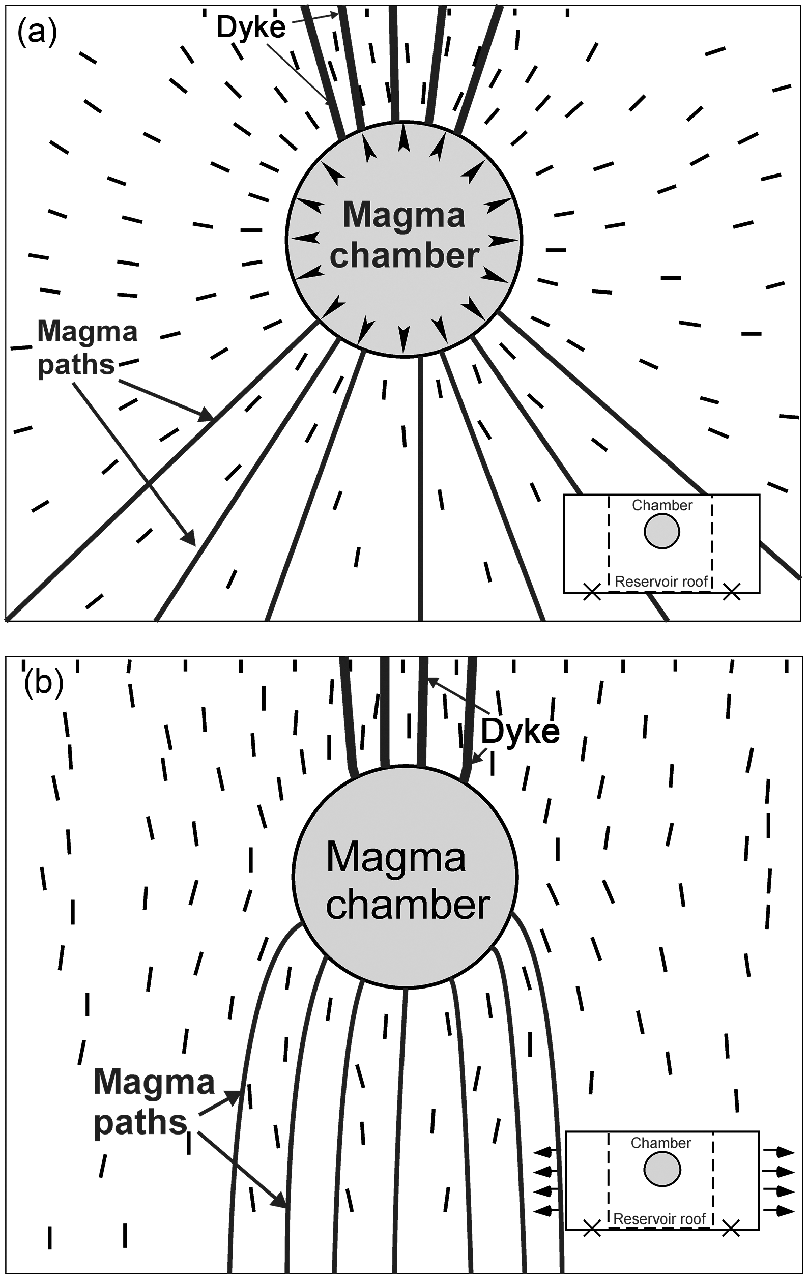
Let us first look at the simplest case, that is, dyke propagation from a shallow chamber located in a homogeneous and isotropic crustal segment. The least action/minimum principles indicate that the dyke path should everywhere be perpendicular to σ 3 and therefore follow the trajectories of σ 1 for the shortest distance between t 1 and t 2 (Equation (10)). That the path is straight follows from the arrangement of the σ 1 trajectories (Fig. 19) and is also a well known result from the calculus of variations (Washizu, Reference Washizu1975; Cassel, Reference Cassel2013), demonstrating the fact that a straight line is the shortest distance between given points. Provided that the step-like average rate of dyke propagation (Fig. 16) is approximately constant, the straight path also minimizes the time needed for the propagation among a family of nearby curved or somewhat irregular paths (Figs 15, 18) with the same endpoints, t 1 and t 2.
Theoretical dyke-propagation paths in a homogeneous, isotropic crustal segment. The crustal segment has a uniform Young’s modulus of 40 GPa and a Poisson’s ratio of 0.25, both values being appropriate generalized average static values for the crust in Iceland (Gudmundsson, Reference Gudmundsson1988). The model is fastened at the corners (indicated by crosses) and was made using the boundary-element program BEASY (www.beasy.com). The boundary-element method, with application to BEASY, is described by Brebbia and Dominguez (Reference Brebbia and Dominguez1992) and on the BEASY homepage. Several potential paths from the roof of the shallow chamber (of a circular, vertical cross-section) to the surface are indicated. Also indicated are some potential magma paths from the source reservoir to the floor (lower margin) of the chamber. The dashes show the trajectories of σ 1, the likely dyke paths (and magma paths) being parallel with these. When the loading of the chamber includes (a) internal magmatic excess pressure of 5 MPa (see the inset), the potential dyke paths are more spread out (more fan-shaped) than in (b), where the only loading is external tensile stress of 5 MPa (see the inset). More specifically, the loading conditions in (a) could be reached when the chamber receives new magma from the deeper source. By contrast, the loading conditions in (b) could be reached when a chamber initially in lithostatic/mechanical equilibrium with the host rock becomes subject to tensile stress, such as would be common at divergent plate boundaries.
Of the many straight and potential paths from the source chamber to the surface, the path selected is that from t 1 and parallel with σ1 to t 2 (Fig. 19). The point t 1, which basically determines where the dyke initiates, is the point or location of highest tensile stress concentration at the margin of the chamber, namely where the conditions of Equation (1) are first satisfied. As for point t 2, it is a point on the tip line for an arrested dyke and on the volcanic fissure for a feeder dyke. Using Equations (6) and (21), the dyke-fracture propagation becomes arrested at t 2 somewhere inside the crust when:
 $${G_{{I}}} = {{p_{{o}}^2\left( {1 - {\nu ^2}} \right)\pi a} \over E} \lt {G_{{c}}} = {{d{W_{{s}}}} \over {dA}}$$
where G I is the plane-strain energy release rate, p o is the magmatic overpressure in the dyke, a is half the height (dip dimension) of the dyke, E is Young’s modulus of the host rock, G c is the material toughness of the host rock and Ws is the surface energy needed to form the dyke fracture as it extends in order to form the new surface area A. If the energy release rate during step-like dyke-tip propagation (Fig. 16) is less than the material toughness, the dyke-fracture propagation stops or becomes arrested. Presumably, however, most dykes injected into an approximately homogeneous, isotropic crustal segment would reach the surface, that is, become feeders (Galindo & Gudmundsson, Reference Galindo and Gudmundsson2012).
Currently, it is difficult to forecast exactly where at the boundary of the magma chamber that the rupture leading to dyke injection will occur. Analytical and numerical models can be used to infer regions of highest stress concentration at the chamber boundary during unrest periods, based on the mechanical properties of the host rock and the geometry and properties of the chamber (Gudmundsson, Reference Gudmundsson2020). Additionally, when the chamber ruptures and a dyke initiates, the associated earthquakes provide a rough guide to the approximate location and timing of the rupture, and therefore to the location of t 1 (Gudmundsson et al. Reference Gudmundsson, Bazargan, Hobé, Selek and Tryggvason2021). When the location of t 1 is determined, then the principles above make it theoretically possible to forecast the likely propagation path to the point t 2.
6.b.2. Heterogeneous, anisotropic rock
The above assumptions, namely that the host rock is homogeneous and isotropic, are very common in geodetic studies in volcanology but generally not warranted. Stratovolcanoes are composed of strata, that is, layers, with widely different mechanical properties (which also applies to sedimentary basins and therefore to the host rock of hydrofractures in general). Basaltic edifices (shield volcanoes) are composed of layers where the mechanical properties are more uniform than in stratovolcanoes, but Young’s modulus can still vary by orders of magnitude between compliant scoria or soil layers and stiff lava flows (or sills) in basaltic edifices. The rocks of real volcanoes and volcanic zones are also heterogeneous (meaning that material properties change with position in the body), but here the focus is on the effects anisotropy (meaning that material properties have different values in different directions at a given point within the body), particularly in connection with layering, on the dyke-propagation paths.
Mechanical layering can have strong effects on the dyke-path geometry and the conditions for dyke-path arrest. We have already discussed the effects of layering on dyke arrest, so here the focus is on the path geometry. Layering gives rise to local stresses that involve changes in the orientation of the trajectories of σ 1 (and, consequently, the orientations of σ 2 and σ 3). Hamilton’s principle implies that the dyke fracture seeks to be everywhere parallel with σ 1 and perpendicular to σ 3 in order to minimize the energy used during the propagation. The dyke fracture also seeks to minimize the time needed to propagate from t 1 to t 2. The propagation velocity of dykes varies somewhat, primarily between c. 0.01 and 1 m s−1 (Gudmundsson et al. Reference Gudmundsson, Bazargan, Hobé, Selek and Tryggvason2021). For typical rates of dyke propagation, say 0.1 m s−1, it follows that minimizing the duration implies minimizing the dyke-path length, for the given constraints.
Of all the possible dyke paths following the trajectories of σ 1 the shortest path between t 1 and t 2 would normally be selected. To discover what this implies, we can consider a simple two-dimensional model where the stiffnesses (Young’s moduli) of the layers gradually increases with depth (as is common) in the volcanic zone/volcano (Fig. 20). Five possible paths of feeder dykes (out of numerous potential paths) are indicated. The shortest path, and the one likely to be selected in this case (but also depending on the tensile stress concentration around the chamber), is one in the centre. The trajectories of σ 1 indicate that many of the paths would reach the surface, particularly above the central part of the magma chamber. That is largely because there is little contrast in the mechanical properties (stiffness) of the layers, as would be common if the chamber was located in a basaltic edifice.
Theoretical dyke-propagation paths in a layered crustal segment. The numerical model was made using the finite-element software ANSYS (www.ansys.com). The finite-element method is described by Logan (Reference Logan2002). There are 10 layers above the unit hosting the chamber. The top layer (layer 1) has a Young’s modulus of 10 GPa, which then gradually increases with depth by 2 GPa for each layer so that layer 10 has a Young’s modulus of 28 GPa and the layer hosting the chamber a Young’s modulus of 30 GPa. All the layers have a Poisson’s ratio of 0.25. The range in values for Young’s modulus and Poisson’s ratios of rocks in general is provided by Gudmundsson (Reference Gudmundsson2011). The only loading in the model is magmatic excess pressure of 10 MPa in the chamber. The model is fastened at the corners (indicated by crosses). This crustal segment is approaching homogenization as regards mechanical layering, as some segments do when they become older. The three potential dyke paths above the central part of the chamber roof are comparatively smooth, whereas the two outermost two paths show greater variation in geometry and overall length from the source to the surface. Hamilton’s principle implies that the paths of least action would be somewhere above the central part of the chamber.
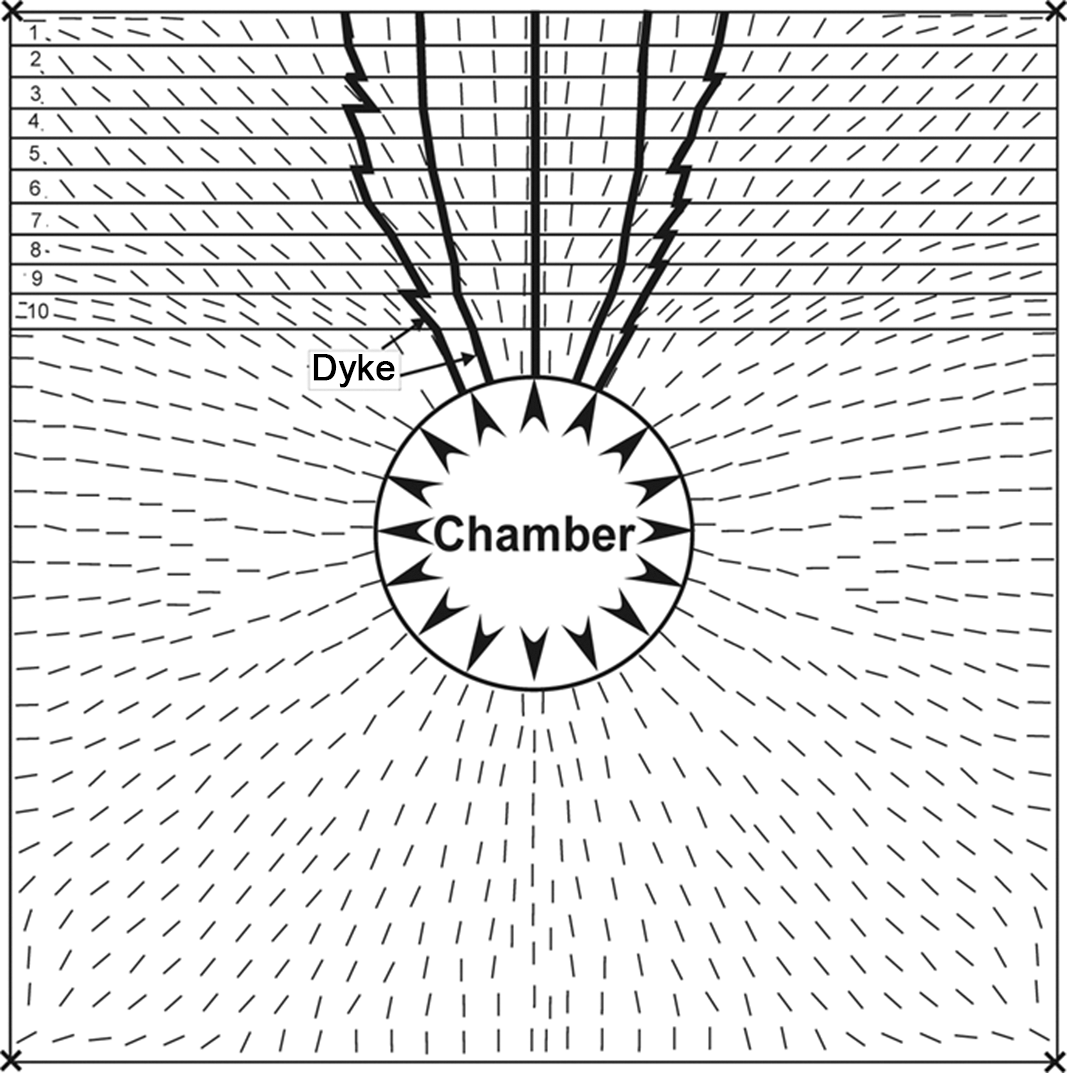
The 30-layer model (Fig. 21) provides more details of possible dyke paths. The shallow magma chamber is located in a single thick layer or unit (with a Young’s modulus of 40 GPa) and subject to 10 MPa excess pressure, which is the only loading in the model. The roof above the chamber is mostly composed of 30 layers of alternating Young’s moduli of 1 GPa and 100 GPa. The contrast in stiffness between the layers is of two orders of magnitude, as is common in many volcanic fields (and in stratovolcanoes in particular). However, the absolute stiffness values in many stratovolcanoes could be somewhat different. The stiff layers might therefore have a Young’s modulus of 50 GPa and the thin layers 0.5 GPa, but the factor to be explored here is the effect of stiffness contrast on potential dyke paths, rather than the absolute stiffnesses (which are all within the general range of Young’s moduli of volcanic rocks; Gudmundsson, Reference Gudmundsson2020).
Some potential paths of dykes and inclined sheets injected from a magma chamber of circular cross-section into a roof composed of 30 layers of alternating Young’s moduli of 1 GPa and 100 GPa. Internal magmatic excess pressure of 10 MPa is the only loading. The numerical model is fastened at the corners (indicated by crosses in the top illustration). The model was made using the finite-element software ANSYS (www.ansys.com; Logan, Reference Logan2002). The top illustration provides an overview of the entire model. The lower-left illustration is a close-up of part of the model, showing the σ 1 trajectories (dashes) in the individual layers above a part of the magma chamber. In the lower-right figure some potential dyke paths, following the σ 1 trajectories, are shown. Only five potential paths are indicated, two of which may possibly reach the surface.

The thicknesses of the layers in the model (Fig. 21) depends on the depth of the magma chamber. For example, if the magma chamber had the top part of its roof at 1.5–2 km, as is common at divergent plate boundaries such as in Iceland (Gudmundsson, Reference Gudmundsson2020), the thickness of each of the 30 layers would be between 50 m and 67 m. Many layers of pillow lava, hyaloclastite and sediments, for example, reach these thicknesses, whereas most ordinary lava flows would be thinner (commonly 5–20 m for basalt). The layering in the model may therefore be regarded as an approximation to the layering exposed in Iceland and many volcanic rift zones, but also appropriate for many crustal segments at convergent plate boundaries.
For this local stress field, the geometry and eventual fate of the dyke path depends much on the location of the point of magma-chamber rupture, that is, the point (line, curve at the surface of the chamber) of origin t 1 of the dyke. Within the thick unit hosting the chamber, some of the injected intrusions in the marginal parts of the roof would be inclined sheets (Fig. 2). However, once a propagation path enters the 30 layers the path geometry becomes more complex, particularly in the upper half of the pile of layers. This is in harmony with many dyke paths observed in the field (Fig. 8). Many of the dykes would also be likely to become arrested (Fig. 12c, d). Of the five theoretical dyke paths indicated here, three would be expected to become arrested, while two have a chance of reaching the surface to supply magma to an eruption. In particular, many dykes would be expected to become arrested in the upper central part of the pile. The arrest is there attributable to the abrupt 90° flip in the orientation of σ 1 in many of the layers in that part. However, in the uppermost five to six layers (i.e. close to the surface), the orientation of σ 1 flips again by 90°, back to vertical as in the lower layers, and would therefore be favourable to dyke propagation.
Despite being comparatively simple, these numerical models illustrate that the least action or minimum potential energy principles can be used as a means of forecasting the likely dyke-propagation paths during unrest periods with dyke injection. Such forecasts, even if they are rather elementary at this stage, are of great theoretical and practical importance because they allow us to predict the likely paths. Predictions of this kind would include, say, the direction in which a dyke is likely to propagate within a stratovolcano, perhaps many days before the actual propagation is completed. Furthermore, the predicted dyke paths can sometimes be compared with the actual paths, as determined by induced earthquake swarms, almost in real time. However, the latter requires a dense seismic network that is operational at the time of magma-chamber rupture and dyke injection. Some volcanoes and volcanic zones have comparatively dense permanent seismic networks, such as those existing for the volcanic zones of Iceland (e.g. Jakobsdottir, Reference Jakobsdottir2008; Gudmundsson et al. Reference Gudmundsson, Bazargan, Hobé, Selek and Tryggvason2021). These can be used to determine the dyke propagation (Gudmundsson et al. Reference Gudmundsson, Lecoeur, Mohajeri and Thordarson2014), while more details can be obtained through very dense, transportable networks (Agustsdottir et al. Reference Agustsdottir, Woods, Greenfield, Green, White, Winder, Brandsdottir, Steinthorsson and Soosalu2016). During dyke propagation, the earthquakes are generated mainly in the process zone ahead of the propagating dyke tip, but also in the walls of the dyke as a result of the magmatic pressure (Gudmundsson, Reference Gudmundsson2020).
However, these forecasts (Figs 19–21) only consider the effects of layering on the dyke paths. In addition to layering, all volcanoes and volcanic zones contain numerous fractures of varying sizes. The cooling or columnar joints are used to form the paths (Gudmundsson, Reference Gudmundsson1986), but these are generally evenly distributed in the pile and therefore do not encourage the dyke to deviate from the path parallel with σ 1. Field observations show that some dykes use faults as parts of their paths, and those parts would normally not be parallel with σ 1; however, as will be shown in the following section, the parts of dyke paths that may follow faults would still be in agreement with Hamilton’s principle.
6.c. Effects of faults on hydrofracture paths
For a constant tensile strength T 0 (Equation (1)), hydrofracture paths would be expected to follow the trajectories of σ 1. However, all rocks contain fractures, most commonly joints, which are weaknesses used by many hydrofractures (Fig. 14). Many joints are roughly uniformly distributed in the hosting layers, such as columnar joints in lava flows, and would normally not result in significant deviation of a hydrofracture path from the direction of σ 1. However, some hydrofractures use faults for short (Fig. 9) or long (Fig. 22) parts of their paths. In fact, faults commonly contain networks of mineral veins, most of which are extension fractures (Fig. 5). To understand the conditions that favour hydrofractures using faults as parts of their paths, we again focus on dykes (Fig. 23).
Mineral veins along the plane (indicated) of a normal fault in the Bristol Channel, SW England. The fault dissects layers of limestone and shale. The veins are of calcite (Philipp, Reference Philipp2008). The measuring-tape length is 1 m.

When a propagating hydrofracture (here a dyke) meets a fault, such as the normal fault seen here, the hydrofracture may enter the fault and use it as a part of its path (Figs 9, 24). Here we explore the situation where a vertical dyke meets a steeply dipping normal fault, but the analytical results are easily generalized to other types of faults and hydrofractures. As before, σ 1 and σ 3 are the maximum and minimum principal stresses, respectively; σ n is the normal stress on the fault plane; and α is the acute angle between σ 1 and the fault plane. The dyke propagates in steps (Figs 16, 17) and the fracture front propagates much faster than the fluid front, generating a temporary (air- or gas-filled) cavity devoid of magma at the dyke tip, a cavity which the magma subsequently flows into.

By definition, faults are shear fractures and the fault plane is oblique to σ 1 (and oblique to σ 3 as well) at the time of fault formation or slip. The tensile strength across many active or recently active faults is likely to be close to zero. Less energy may therefore be needed for a dyke or a dyke segment to use the fault, even though the segment is not perpendicular to σ 3 but rather to the normal stress on the fault plane σ n, which is always higher than σ 3 for an active fault. Apart from ring dykes, all of which occupy faults, dykes rarely follow faults. However, some will do so for a part of their paths, and here we analyse the conditions under which they would be likely to do so.
When a dyke segment follows a path that is perpendicular to σ n the effective overpressure available to drive the dyke fracture open becomes less than that given by Equation (4), which assumes the dyke segment is perpendicular to σ 3. The normal stress σ n on a fault plane (Fig. 23) is given by:
 $${\sigma _{{n}}} = {{{\sigma _1} + {\sigma _3}} \over 2} - {{{\sigma _1} - {\sigma _3}} \over 2}\cos 2\alpha $$
where σ 1 and σ 3 are the maximum and minimum principal compressive stresses, respectively, and α is the angle between the fault plane and the direction of σ 1. The difference between the normal stress σ n and the minimum principal compressive stress σ 3 is given by:
 $${\sigma _{{n}}} - {\sigma _3} = {{{\sigma _{{d}}}} \over 2}\left( {1 - \cos 2\alpha } \right)$$
where σ d = σ 1 − σ 3, as defined in Equation (4).
Using Equations (1) and (4) in combination with Equation (24), the condition that a dyke is likely to inject an existing fault and use it as a part of its path becomes:
 $${\sigma _{{n}}} - {\sigma _3} = {{{\sigma _{{d}}}} \over 2}\left( {1 - \cos 2\alpha } \right)\le\Delta{T_0}$$
where
 $${{\Delta }}{T_0} = T_0^{{\sigma _3}} - T_0^{{\sigma _{{n}}}}$$
is the difference between the tensile strength along a potential dyke path that is perpendicular to σ 3 (and parallel with σ 1) and a dyke path that is perpendicular to σ n. If tensile strength along the path perpendicular to σ n is zero, which is probably often the case for an active or recently active fault, then we have:
 $$\Delta {T_0} = {T_0}$$
Equation (4) gives the dyke/hydrofracture overpressure assuming that the dyke segment opens up against σ
3. The overpressure is less when the dyke-fracture opening is against σ
n. Denoting the overpressure against σ
n by $p_{{o}}^{{\sigma _{{n}}}}$
and using Equations (4) and (25), we get:
$p_{{o}}^{{\sigma _{{n}}}}$
and using Equations (4) and (25), we get:
 $$p_{{o}}^{{\sigma _{{n}}}} = {p_{{e}}} + \left( {{\rho _{{r}}} - {\rho _{{m}}}} \right)gh + {{{\sigma _{{d}}}} \over 2}\left( {1 + \cos 2\alpha } \right).$$
As long as α is positive, in which case ${\sigma _{{n}}} \ne {\sigma _3}$
, then
${\sigma _{{n}}} \ne {\sigma _3}$
, then $p_{{o}}^{{\sigma _{{n}}}} \lt \;p_{{o}}^{}$
, that is, the overpressure in Equation (28) is less than that in Equation (4).
$p_{{o}}^{{\sigma _{{n}}}} \lt \;p_{{o}}^{}$
, that is, the overpressure in Equation (28) is less than that in Equation (4).
The energies needed to form a dyke segment in a direction perpendicular to σ n and σ 3 can now be compared. Work, which is force × displacement, is positive if the work is in the direction of the force, but negative if the work is in a direction opposite to the force. The work W needed to form a dyke segment of final volume ΔV v against the normal stress σ n is:
 $$W = {{\Delta }}{V_{{v}}}{\sigma _{{n}}}$$
For the segment of the same volume opened against σ 3, the work is:
 $$W = {{\Delta }}{V_{{v}}}{\sigma _3}$$
The force or overpressure that opens the dyke segment varies linearly with the opening displacement, so that the corresponding elastic energy must be multiplied by one-half. The total energy $U_{{t}}^{{\sigma _{{n}}}}$
needed to form the dyke fracture, that is, rupture the rock and then open the rupture/fracture up against σ
n is therefore:
$U_{{t}}^{{\sigma _{{n}}}}$
needed to form the dyke fracture, that is, rupture the rock and then open the rupture/fracture up against σ
n is therefore:
 $$U_{{t}}^{{\sigma _{{n}}}} = {W_{{s}}} + {{{\sigma _{{n}}}{{\Delta }}{V_{{v}}}} \over 2}$$
where Ws is the surface energy (Equation (15)). Similarly, the total energy needed to form and open the dyke segment against σ 3 is:
 $$U_{{t}}^{{\sigma _3}} = {W_{{s}}} + {{{\sigma _3}{{\Delta }}{V_{{v}}}} \over 2}$$
When the surface energy of rupture Ws is constant for the host rock of a given dyke segment then, because σ 3 < σ n, by comparing Equations (31) and (32) it follows that less energy is needed to form a segment perpendicular to σ 3 than to σ n. As expected, a dyke (and any hydrofracture) therefore tends to follow the path perpendicular to σ 3, namely the path parallel with σ 1.
If the tensile strength across a recently active fault is zero while being several mega-pascals along the potential dyke path following σ
1 at a given locality, then Equations (25)–(27) suggest that less energy, or less action, for a dyke segment of a given length is needed if the dyke follows the recently active fault than if the dyke forms its own path (rupturing the rock) along σ
1. More specifically, a dyke may follow an existing fault along part of its path (Fig. 24) if the difference ${\sigma _{{n}}} - {\sigma _3}$
(Equation (25)) is less than the difference in tensile strength (Equation (26)) between the rock along σ
1 and along the fault. The stress difference
${\sigma _{{n}}} - {\sigma _3}$
(Equation (25)) is less than the difference in tensile strength (Equation (26)) between the rock along σ
1 and along the fault. The stress difference ${\sigma _{{n}}} - {\sigma _3}\;$
depends much on the angle α between the fault plane and σ
1 (Equation (24)); the smaller the angle α, the more likely the dyke is to enter the fault plane on meeting the plane (Figs 23, 24). In particular, for normal faults, as are most common in volcanic zones with dyke injection, small α means steeply dipping faults, which are the most likely to be used as parts of dyke paths. However, in some volcanic areas vertical strike-slip faults are common, some of which may be used as parts of dyke paths, particularly close to the surface (Gudmundsson et al. Reference Gudmundsson, Bazargan, Hobé, Selek and Tryggvason2021).
${\sigma _{{n}}} - {\sigma _3}\;$
depends much on the angle α between the fault plane and σ
1 (Equation (24)); the smaller the angle α, the more likely the dyke is to enter the fault plane on meeting the plane (Figs 23, 24). In particular, for normal faults, as are most common in volcanic zones with dyke injection, small α means steeply dipping faults, which are the most likely to be used as parts of dyke paths. However, in some volcanic areas vertical strike-slip faults are common, some of which may be used as parts of dyke paths, particularly close to the surface (Gudmundsson et al. Reference Gudmundsson, Bazargan, Hobé, Selek and Tryggvason2021).
Some ordinary dykes, such as the basaltic dyke here (indicated), follow faults for a while along their paths, particularly steeply dipping normal faults. The fault dissects a swarm of gently dipping inclined sheets (one sheet is indicated). The structures seen here are a part of a fossil central volcano in West Iceland.

7. Discussion
One of the important unsolved problems in solid-earth geosciences is to provide a theoretical framework that allows us to make reliable forecasts for rock-fracture propagation paths through layered and faulted rocks. The reason that the solution of this problem is so important is that brittle deformation, which dominates in the upper part of the crust, is mostly through fracture initiation and propagation, and most crustal segments are composed of layered and faulted rocks. Fracture propagation therefore controls earthquakes, landslides (lateral collapses), calderas (vertical collapse), and the formation and development of all types of plate boundaries. Furthermore, fractures to a large degree determine fluid transport in the Earth’s crust, including flow of groundwater, geothermal water and hydrocarbons. Additionally, most volcanic eruptions are supplied with magma through magma-driven fractures, primarily inclined sheets and dykes.
There has been much research on hydrofracture propagation over many decades, particularly in the hydrocarbon industry (Valko & Economides, Reference Valko and Economides1995; Yew & Weng, Reference Yew and Weng2014; Shapiro, Reference Shapiro2018). For more than 70 years, conventional hydraulic fractures have been propagated from vertical wells laterally for distances of up to 1 km or more, with the aim of increasing the permeability (for oil and gas) of the target layer. In recent decades, a technique has been developed whereby hydraulic fractures are injected vertically from horizontal wells in order to obtain gas from tight shale layers (Wu, Reference Wu2017; Shapiro, Reference Shapiro2018). Some of the vertical hydraulic fractures exceed 1 km in dip dimension (height) and therefore have dip dimensions similar to those of many radial dykes and inclined sheets.
In conventional human-made hydraulic fracturing, the likely propagation path of a fracture injected laterally in order to stay in the same mechanical unit/layer can often be forecast with reasonable reliability. The forecasts are based on current stress data and other mechanical information, and made easier since the fracture is (assumed to be) confined to a single mechanical unit (Valko & Economides, Reference Valko and Economides1995; Yew & Weng, Reference Yew and Weng2014; Shapiro, Reference Shapiro2018). In unconventional vertical propagation of hydraulic fractures, such as used in the extraction of gas from shale, the fractures propagate through layered and faulted rocks. The forecast paths are then much less reliable, with the fractures commonly becoming deflected laterally along contacts to form water sills (Fisher & Warpinski, Reference Fisher and Warpinski2011; Fisher, Reference Fisher2014) or deflected into faults (Davis et al. Reference Davis, Mathias, Moss, Hustoft and Newport2012).
More specifically, the propagation paths of thousands of vertically injected hydraulic fractures have been studied through microseismicity. Many hydraulic fractures have been observed to deflect into sub-horizontal contacts, while some have deflected into faults and used them as parts of their paths (Fisher & Warpinski, Reference Fisher and Warpinski2011; Davis et al. Reference Davis, Mathias, Moss, Hustoft and Newport2012; Flewelling et al. Reference Flewelling, Tymchak and Warpinski2013; Lacazette & Geiser, Reference Lacazette and Geiser2013). Deflection of vertical hydraulic fractures into contacts to form water sills is particularly common at crustal depths of less than 700–800 m (Fisher, Reference Fisher2014). The general conditions for hydrofracture arrest have also been studied; Forbes Inskip et al. (Reference Forbes Inskip, Browning, Meredith and Gudmundsson2020) provide new numerical models on these conditions and a review of much of the literature.
As for natural hydrofractures such as igneous sheet-like intrusions, the details of no new paths of dykes (excluding multiple injections) or inclined sheets have ever been successfully forecast (Gudmundsson, Reference Gudmundsson2020). By this I mean that it has not been possible to forecast whether or not a new dyke path (a dyke injected during an unrest period) will become arrested or reach the surface. In the latter case, it has not been possible to forecast where and when it would reach the surface, or how large the resulting volcanic fissure is likely to be, despite the fact that many dyke (and some inclined sheet and sill) propagation paths during unrest periods in active volcanoes/volcanic zones have been well monitored using seismic methods. The results have indicated the overall propagation paths as well as providing crude estimates of the rate of dyke propagation. Dyke propagation for horizontal distances (strike-dimensions) of many tens of kilometres have therefore been recorded in Iceland (Gudmundsson, Reference Gudmundsson, Baer and Heimann1995; Gudmundsson et al. Reference Gudmundsson, Lecoeur, Mohajeri and Thordarson2014; Agustsdottir et al. Reference Agustsdottir, Woods, Greenfield, Green, White, Winder, Brandsdottir, Steinthorsson and Soosalu2016). Similarly, many dyke-propagation events in the Manda Hararo-Dabbahu spreading centre in Africa from 2005 to 2010 were recorded seismically (Grandin et al. Reference Grandin, Jacques, Nercessian, Ayele, Doubre, Socquet, Keir, Kassim, Lemarchand and King2011). Dyke-propagation events in the volcano Etna in Italy have also been recorded, some primarily from surface deformation of very shallow dykes (Falsaperla & Neri, Reference Falsaperla and Neri2015), and in Kilauea in Hawaii (Rutherford & Gardner, Reference Rutherford, Gardner, Sigurdsson, Houghton, McNutt, Rymer and Stix2000).
Most of the above events have been interpreted as primarily related to lateral dyke propagation; however, some of the recorded dyke injections have been primarily through vertical propagation. These include some dyke-propagation events in Piton de la Fournaise in Reunion, France and, most recently, the dyke-propagation events that eventually reached the surface to supply magma to the 2021 Fagradalsfjall eruption in Iceland (Gudmundsson et al. Reference Gudmundsson, Bazargan, Hobé, Selek and Tryggvason2021). Both the lateral and vertical dyke-propagation events vary widely as regards rates, but are most commonly in the range of 0.01–1 m s−1.
Arrested dykes and inclined sheets, and the surface deformation they induce, have been widely studied. Recent publications on these topics, summarizing much of the previous research, are by Dzurisin (Reference Dzurisin2006), Segall (Reference Segall2010), Kavanagh & Sparks (Reference Kavanagh and Sparks2011), Tibaldi (Reference Tibaldi2015), Al Shehri & Gudmundsson (Reference Al Shehri and Gudmundsson2018), Bazargan & Gudmundsson (Reference Bazargan and Gudmundsson2019, Reference Bazargan and Gudmundsson2020) and Drymoni et al. (Reference Drymoni, Browning and Gudmundsson2020). These and related publications demonstrate that most observed segments of dykes and inclined sheets – and of hydrofactures in general (Gudmundsson & Brenner, Reference Gudmundsson, Fjeldskaar and Brenner2002; Forbes Inskip et al. Reference Forbes Inskip, Browning, Meredith and Gudmundsson2020) – become arrested at or just below contacts between mechanically dissimilar rocks, particularly at contacts where the layer above the contact is considerably stiffer (with higher Young’s modulus) than the layer below the contact. Hydraulic fractures are also commonly observed to arrest at contacts between dissimilar layers (Fisher & Warpinski, Reference Fisher and Warpinski2011; Fisher, Reference Fisher2014), and fracture arrest can normally be attributed to Cook–Gordon delamination, stress barrier and/or elastic mismatch (Gudmundsson, Reference Gudmundsson2011). There have also been many studies on the percentage of dykes occupying faults (Gudmundsson, Reference Gudmundsson1983), as well as of dyke–fault interactions (Rubin & Pollard, Reference Rubin and Pollard1988; Rubin, Reference Rubin1995; Tibaldi, Reference Tibaldi2015; Drymoni et al. Reference Drymoni, Browning and Gudmundsson2021).
While the above works have focused on various aspects of hydrofracture emplacement, arrest, and induced earthquakes and surface deformation, the physics of formation of hydrofracture paths has received comparatively little attention. There have been discussions in the fracture mechanics literature on dynamic fracture propagation (Freund, Reference Freund1998; Ravi-Chandar, Reference Ravi-Chandar2004; Shulka, Reference Shulka2006), but the results apply primarily to propagation in homogeneous, isotropic materials; are not based on Hamilton’s principle; and are more appropriate for earthquake rupture as regards velocities (even if these works focus on mode I cracks) than the comparatively slow propagation of fluid-driven fractures in layered rock bodies.
In this paper a new theoretical framework is provided for forecasting the likely propagation paths of hydrofractures through layered and faulted rocks. At this stage, the framework does not apply to shear fractures such as faults. With further development and proper adjustment of the boundary conditions, it may be possible to include shear-fracture propagation paths in this theoretical framework in the future. The proposal is based on the suggestion that hydrofracture paths are controlled by Hamilton’s principle of least action.
Based on Hamilton’s principle, it is suggested that of the theoretically infinite number of possible paths that a given hydrofracture may follow, the entire fracture (and each fracture segment) selects the path of least (minimum) action. More specifically, the path chosen is that along which the variation of the action is zero. Action has the dimensions of energy × time and the units of J s (joule-second). For an elastic solid, such as a host-rock body, action (S) is the kinetic energy (T) minus the potential energy due to generalized external forces (V) and minus the strain energy due to internal forces (U), or S = T – V – U. The right-hand side of this equation is also referred to as the Lagrangian (the difference between the kinetic and the total potential energy). In the theoretical framework proposed here, which applies to conservative systems, the path taken by a hydrofracture is therefore normally the one along which the energy transformed (released) multiplied by the time taken for the propagation is the least (is a minimum).
For the normally slow-propagating hydrofracture – with typical rates for dykes of 0.01–1 m s−1 in comparison with seismic ruptures whose rates are of the order of km s−1 – the kinetic energy may with some justification be assumed zero. On that assumption, Hamilton’s principle of least action reduces to the principle of minimum potential energy (or least work). This latter principle states that of all the possible displacement fields (configurations) of an elastic body that satisfy the constraint conditions and the external and internal forces, the actual (true) displacements are those that make the total potential energy of the body a minimum. This principle applies only to (linear and non-linear) elastic bodies, and was postulated as a general principle for dyke propagation by Gudmundsson (Reference Gudmundsson1986).
A quantitative comparison between the paths forecast here and the actual observed paths must, at this stage, be of a general (statistical) nature. Neither the present method or other methods developed over the years have so far been used to make a reliable prediction of the details of dyke-propagation path during actual volcano unrest and dyke injection. Such a prediction is the next development of the theories and observations presented here and should, at first, be applied to volcanoes/volcanic zones where the layering and faulting is well known, such as from exposures in caldera walls, cliffs and drill holes. Unconventional (vertical) hydraulic fracturing, where drilling provides information on the mechanical layering, can also be used to test the present theories of hydrofracture propagation paths. While rigorous testing of the forecasts has not be possible so far, the general path predictions are supported by direct field observations, both as regards the paths of dykes (Figs 1, 6, 8, 13, 14, 18) and the paths of mineral veins (Figs 4, 5, 9, 11, 12).
8. Conclusions
The main conclusions of the paper may be summarized as follows.
-
The principal aim of this paper is to explain and provide a theoretical framework to forecast the paths of fluid-driven fractures, that is, hydrofractures when propagating through layered, heterogeneous and faulted crustal segments. The term hydrofracture includes all dykes, inclined sheets, sills, most mineral veins and many joints, as well as human-made hydraulic fractures. For the first time, Hamilton’s principle of least action is here applied to hydrofractures with a view of forecasting their likely paths through layered rocks. Additionally, using energy considerations, a quantitative estimate is made of the potential of existing faults acting as parts of hydrofracture paths.
-
It is proposed that of the theoretically infinite number of possible paths that a given hydrofracture may follow, it selects the path of least (minimum) action as determined by Hamilton’s principle. The path chosen is therefore that along which the variation of the action is zero, which means that the selected path is the one where the energy transformed (released) multiplied by the time taken for the propagation is the least (is a minimum).
-
For many hydrofractures the kinetic energy may be taken as zero, in which case Hamilton’s principle of least action reduces to the principle of minimum potential energy. This latter principle states that of all the possible displacement fields (configurations) of an elastic body, such as a rock body or a crustal segment, that satisfy the constraint conditions and the external and internal forces, the actual (true) displacements are those that make the total potential energy of the body a minimum.
-
Hydrofractures advance their tips/fronts in steps, with a time lag between the fracture front and the fluid front. Each vertical step may be similar in length to the thickness of the layers, such as lava flows (for dykes) or shale/limestone layers (for hydrofractures in sedimentary basins), through which the hydrofracture propagates.
-
In the present theoretical framework, each propagation step of a hydrofracture is controlled by Hamilton’s principle or, in the case where the kinetic energy is omitted, by the principle of minimum potential energy. The energy needed to advance the dyke fracture is the surface energy, whereas the energy transformed or released during the hydrofracture propagation is part of the total potential energy (potential energy due to external forces and strain energy due to internal forces).
-
When applied to dykes, some of the main conclusions of the new framework are as follows. When a crustal segment is regarded as homogeneous, isotropic and non-fractured, dyke-propagation paths are everywhere perpendicular to the trajectories of the minimum compressive (maximum tensile) principal stress σ 3 and therefore follow the trajectories of the maximum principal compressive stress σ 1.
-
For a faulted and/or a layered (anisotropic) crustal segment or rock body, the dyke-propagation paths can locally follow existing faults for a while and therefore be oblique to the trajectories of the maximum principal compressive stress σ 1 (and oblique to σ 3). Whether the dyke uses a fault as a part of its path depends primarily on: (1) the dip of the fault (steep faults are the most likely to be used); and (2) the tensile strength across the fault compared with the tensile strength of the host rock along a path following the direction of σ 1. The results suggest that dykes use faults as parts of their paths primarily if the fault is comparatively steeply dipping, preferably a normal fault or currently in an extensional regime, and with close to zero tensile strength.
Acknowledgements
The results presented here are based on work over many years that has been supported by several funding agencies, such as the Icelandic Science Foundation, the Research Council of Norway, the European Commission and the Natural Environment Research Council of the United Kingdom. I thank the journal reviewers for very helpful comments.


 Open access

