


Nomenclature
- F
-
feasibility measure of a constraint $g$
$g$
-
${g_M}$
-
damping per mode M
-
$\hat g({\textbf{x}})$
-
constraint surrogate prediction at point
${\textbf{x}}$
-
${N_c}$
-
number of basis functions
-
${\textbf{n}}$
-
number of training samples
-
${p_n}$
-
Kriging model exponent parameters
-
${\hat s^2}({\textbf{x}})$
-
Kriging prediction variance
-
$\hat s$
-
Kriging prediction standard deviation
-
${{\textbf{w}}_{\textbf{n}}}\;$
-
Kriging model weight for the n-th basis function
-
${\textbf{x}}$
-
design variable vector
-
${{\textbf{x}}^{({\textbf{i}})}}$
-
i-th sampled design point
-
${\textbf{x}}_c^{(n)}$
-
centre of the
$n$
-th basis function -
${\textbf{y}}$
-
vector of observed responses at training points
-
${{\textbf{y}}_{{\textbf{min}}}}$
-
best observed objective value
-
$\hat y(\textbf{x})$
-
Kriging prediction at point
${\textbf{x}}$
-
$\mathbf{1}$
-
vector of ones


Greek symbols
-
${\theta _n}$
-
Kriging model length parameters
-
${\lambda _b}$
-
global buckling eigenvalue
-
$\hat \mu $
-
maximum likelihood estimate of the mean
-
${\hat \sigma ^2}$
-
maximum likelihood estimate of the variance
-
${\sigma _{VM}}$
-
Von Mises stress
-
${\sigma _x}$
-
x-component of stress
-
${{\Phi }}(.,.)$
-
cumulative distribution function
-
$\phi(.)$
-
probability density function
-
${[}\Psi{]}$
-
correlation matrix of training points
-
$\psi (.,.)$
-
kernel (correlation) function
-
$\psi $
-
correlation vector between prediction point and training points


1.0 Introduction
1.1 Background
The design of lighter, stronger and more efficient aircraft structures remains a critical challenge in aerospace engineering. This challenge has intensified with the increasing use of composite materials and with the ever-increasing aspect ratio of modern airliner wings. Composites offer high specific strength and stiffness along with enhanced tailorability through fiber orientation and laminate stacking sequence. On the other hand, the advent of high-aspect ratio composite airframes has also contributed to the decrease of the induced drag and subsequent increase of the lift-to-drag ratio, which in turn improves fuel efficiency.
Aircraft wing structures are among the most critical and demanding components. They are subjected to diverse and multidisciplinary loading conditions, including aeroelastic forces and buckling, and must simultaneously satisfy stringent regulatory requirements on strength, stability and stiffness while maintaining weight efficiency. Consequently, the optimisation of aircraft wings – balancing all these requirements while minimising structural mass – is of paramount importance. This task becomes even more challenging in the case of composites, where additional design variables such as ply thickness and orientation further complicate the design space. Furthermore, the increased aspect-ratio wings exhibit elevated flexibility that tend to induce a closer coupling between the structure and the surrounding fluid, aggravating static and dynamic aeroelastic phenomena.
The development of contemporary wing structures demands a multidisciplinary approach, with careful attention to these factors incorporated throughout the early design stages. At the conceptual design stage, low-fidelity models are employed for the structural and aerodynamic analysis. Typically, equivalent beam or plate models are used for the structures, while for the aerodynamics planar panel methods such as the vortex lattice method (VLM) and the doublet lattice method (DLM) are employed [Reference Afonso, Vale, Oliveira, Lau and Suleman1]. Such models, despite being widely established [Reference Haftka2–Reference Triplett4], are still of interest to the scientific community, since they offer greater computational efficiency in comparison with higher-fidelity models. Recent developments focus on the analysis of high-aspect ratio wings, aiming at the inclusion of aeroelastic and nonlinear effects for both the structure and aerodynamic disciplines [Reference Calderon, Cooper, Lowenberg, Neild and Coetzee5–Reference Kilimtzidis and Kostopoulos8].
At the preliminary design stage, the fidelity of the corresponding models is increased, using finite element method (FEM) models for the structures, while for the aerodynamics mid-to-high fidelity, ranging from 3D transonic small disturbance to Reynolds-averaged Navier-Stokes models (RANS) [Reference DeBlois and Abdo9, Reference Piperni, DeBlois and Henderson10]. The inclusion of aeroelastic effects is also of paramount importance to the analysis, with a wide variety of coupling fluid-structure interaction (FSI) algorithms being present in the literature [Reference de Boer, van Zuijlen and Bijl11–Reference van Zuijlen, Bosscher and Bijl14].
The fidelity of these models directly influences the reliability of the predictions and, consequently, the effectiveness of the design. Within this computational setting, optimisation has emerged as a central tool for systematically improving aircraft structures. Structural optimisation enables designers to explore large design spaces and identify weight-efficient solutions that still satisfy strength, stability and aeroelastic requirements. A wide range of optimisation approaches has been proposed to address these challenges. The majority of existing studies emphasise global sizing optimisation, where simplified FEM are employed to distribute stiffness and material across the wing efficiently [Reference Anderson, Cardona and Mason15–Reference Stanford20]. In most cases, wing geometry is fixed, and only component thicknesses are treated as design variables. Furthermore, the optimisation framework heavily relied on repetitive FEM-based simulations, exacerbating the computational effort. In recent years, significant research efforts have focused on the multidisciplinary design and aeroelastic tailoring of composite wings, particularly in the context of high-aspect-ratio configurations. Notable examples include large-scale industrial and collaborative research initiatives, such as the aeroelastic tailoring project involving Embraer [Reference Maathuis, Castro and De Breuker21, Reference Silva, do Prado, Cabral, De Breuker and Dillinger22], as well as several research programmes addressing composite wingbox optimisation, load alleviation and aeroelastic performance through material tailoring and structural layout optimisation [Reference Othman, Silva, Cabral, Prado, Pirrera and Cooper23–Reference Streitenberger and Feldwisch25]. These studies typically combine aerodynamic, structural and aeroelastic analyses within multidisciplinary design optimisation (MDO) frameworks, often emphasising tow-steering, stiffness tailoring or aeroelastic load redistribution. While these contributions have demonstrated the potential of composite aeroelastic tailoring, they frequently rely on fixed structural layouts, specialised tailoring variables or problem-specific implementations. In contrast, the present work focuses on the development of a fully automated, parametric finite-element-based framework integrated with surrogate-based optimisation, enabling efficient exploration of a broader structural design space under static, buckling and flutter constraints.
1.2 Motivation
The motivation for this work arises from two key directions. First, most structural optimisation studies assume a fixed wingbox geometry and vary only thickness distributions, which restricts the scope for identifying innovative structural layouts. In contrast, the present framework introduces a fully parametric FEM in which both geometry and component thicknesses are treated as design variables, enabling a substantially broader design space. Second, the computational burden of evaluating high-fidelity aeroelastic and structural analyses motivates the use of efficient optimisation strategies. SBO is therefore adopted to accelerate the design process, allowing efficient exploration of the extended design space while minimising the number of costly FEM-based simulations. To address these limitations, the present study introduces an SBO framework tailored for full-aircraft configurations. SBO techniques have been increasingly applied in aerospace design, offering rapid and efficient exploration of large design spaces [Reference Kilimtzidis and Kostopoulos26–Reference Nikolaou, Kilimtzidis and Kostopoulos29]. By replacing repeated FEM-based simulations with accurate approximations of the underlying objective functions and constraints, SBO frameworks significantly reduce computational cost while maintaining predictive accuracy. Together, these two pillars – parametric geometry with thickness variation and SBO – form the foundation of a framework aimed at delivering weight-efficient, aeroelastically robust composite wing designs. To the best of the authors’ knowledge, no existing framework in the literature has simultaneously combined a fully parametric FEM with SBO for composite wing structures, underlining the novelty and significance of the present study.
The present research study is organised as follows. Section 2 presents the optimisation framework, including the structural model, aeroelastic analysis and surrogate modeling strategy. Section 3 describes the numerical implementation and case study. Section 4 discusses the results, and Section 5 summarises the conclusions.
2.0 Methodology
2.1 Reference wing geometry
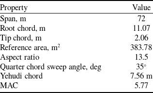
For the analysis, the undeflected common research model (uCRM-13.5) has been selected as the reference aircraft model. This configuration represents a high-aspect-ratio derivative of the original CRM wing [Reference Vassberg, Dehaan, Rivers and Wahls30] and serves as a benchmark for CFD and aero-structural optimisation studies. The uCRM-13.5 model [Reference Brooks, Kenway and Martins31] is widely used to assess realistic, contemporary and next-generation aircraft configurations. The key geometric parameters of each component are summarised in Table 1.
uCRM-13.5 geometric characteristics

The internal configuration of the wing comprises skins, ribs, as well as three spars, with the middle one extending to the Yehudi break. Furthermore, to increase the bending and buckling stiffness of the wing, spar caps and stringers are also employed. An exploded view of the internal configuration is presented in Fig. 1.
Internal configuration of the uCRM wing.

2.2 FEM model
A FEM model of the uCRM wing is generated based on the external surfaces of the aircraft. For the skins, spars, and ribs, four-noded quadrilateral shell elements (CQUAD4) are used, while the spar caps and stringers are modeled using beam elements (CBEAM), also accounting for the relevant offset values. As an initial design point, a reference balanced and symmetric lay-up and specifically the ${[{(45/0/ - 45/90)_{2s}}]_s}$
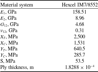
, has been considered for all the relevant wing parts. The Hexcel IM7/8552 composite material system is selected for the relevant parts of the wing, with the respective B-Basis material properties, strength values and cured ply thickness listed in Table 2. For the beam elements and to simplify the analysis, rectangular cross-sections are considered. The respective thickness, nevertheless, is calculated based on the aforementioned laminate, since they are also considered to be manufactured of the provided composite material. However, only isotropic materials are permitted for the definition of the CBEAM elements. As a result, and since the baseline lay-up is symmetric, equivalent laminate axial and shear moduli,
${[{(45/0/ - 45/90)_{2s}}]_s}$
, has been considered for all the relevant wing parts. The Hexcel IM7/8552 composite material system is selected for the relevant parts of the wing, with the respective B-Basis material properties, strength values and cured ply thickness listed in Table 2. For the beam elements and to simplify the analysis, rectangular cross-sections are considered. The respective thickness, nevertheless, is calculated based on the aforementioned laminate, since they are also considered to be manufactured of the provided composite material. However, only isotropic materials are permitted for the definition of the CBEAM elements. As a result, and since the baseline lay-up is symmetric, equivalent laminate axial and shear moduli, ${E_{eq}}$
and
${E_{eq}}$
and ${G_{eq}}$
respectively, are computed using Equations (1) and (2) [Reference Kassapoglou32]:
${G_{eq}}$
respectively, are computed using Equations (1) and (2) [Reference Kassapoglou32]:
 \begin{align}{E_{eq}} = \frac{1}{t}\left( {{A_{11}} - \frac{{A_{12}^2}}{{{A_{22}}}}} \right)\end{align}
 \begin{align}{G_{eq}} = \frac{{{A_{66}}}}{t}\end{align}
where $t$
is the thickness,
$t$
is the thickness, ${A_{11}}$
,
${A_{11}}$
, ${A_{12}}$
,
${A_{12}}$
, ${A_{22}}$
and
${A_{22}}$
and ${A_{66}}$
the corresponding terms of the extensional stiffness matrix of a laminate.
${A_{66}}$
the corresponding terms of the extensional stiffness matrix of a laminate.
Composite materials properties [Reference Marlett33]

Regarding the boundary conditions, the wing is assumed to be clamped at its root section, thus fixing all relative nodal degrees of freedom (DOF). External masses corresponding to the fuel and engines of the wing are also included in the FEM model. In particular, all of the masses are modeled via concentrated mass (CONM2) point elements and are connected to the main wing structure via multi point constraints (MPC), specifically RBE2 and RBE3. The resulting FEM mesh of the wing model is presented in Fig. 2.
FEM model of the uCRM wing.

2.3 DLM aerodynamics model
The aerodynamic model of the aircraft was generated using the DLM. In this framework, only the lifting surfaces, namely the wing and tail, were represented, while the fuselage was neglected. The DLM represents lifting surfaces as planar panels [Reference Albano and Rodden34], which means that thickness, camber and twist effects are not inherently captured. To account for these effects and obtain accurate aerodynamic loads, the W2GJ vector must be defined in NASTRAN. Specifically, the camber line is determined at each aerofoil section of the lifting surfaces, and the corresponding W2GJ vector contains the derivative of the camber line evaluated at the collocation points. Figure 3 illustrates the W2GJ vector distribution.
DLM model W2GJ vector distribution.

Coupling between the aerodynamic and structural models was carried out using infinite plate splines. For the splining procedure, nodes were selected near the leading and trailing edges as well as at rib-spar intersections. This ensured proper load transfer and distribution, while avoiding unrealistic local load concentrations.
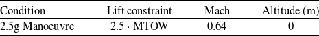
For the static aeroelastic analysis, a critical load case corresponding to a $2.5g$
pull-up manoeuvre was considered. The conditions for this case are summarised in Table 3, with the maximum take-off weight (MTOW) set to
$2.5g$
pull-up manoeuvre was considered. The conditions for this case are summarised in Table 3, with the maximum take-off weight (MTOW) set to $268 \times {10^3}$
kg [Reference Gray35]. The aerodynamic loads were generated by adjusting the angle-of-attack (AoA) accordingly.
$268 \times {10^3}$
kg [Reference Gray35]. The aerodynamic loads were generated by adjusting the angle-of-attack (AoA) accordingly.
Aerodynamic critical load case summary

The dynamic aeroelastic behaviour was also investigated through flutter analysis. Reduced-frequency-dependent aerodynamic loads were computed for ten reduced frequencies ranging from 0.001 to 2, at a Mach number equal to the cruise value of 0.85. The velocity range examined was 100–1,000 m/s. The flutter eigenvalue problem was solved using the $p$
-
$p$
- $k$
method implemented in NASTRAN SOL 145, enabling the identification of divergence and flutter instabilities.
$k$
method implemented in NASTRAN SOL 145, enabling the identification of divergence and flutter instabilities.
3.0 SBO framework
3.1 Kriging model
An SBO framework was developed for structural sizing of the aircraft. The framework consists of three stages: sampling, surrogate model construction and model updating [Reference Alexandrov, Dennis, Lewis and Torczon36]. For the sampling stage, Latin hypercube sampling (LHS) [Reference McKay, Beckman and Conover37] was adopted, as it maximises the distance between samples while ensuring that the projections along each axis follow a prescribed probability distribution.
The surrogate model is denoted as $\hat f\left( {{\textbf{x}},w} \right)$
, where
$\hat f\left( {{\textbf{x}},w} \right)$
, where ${\textbf{x}}$
is the design variable vector and
${\textbf{x}}$
is the design variable vector and $w$
the model parameters. In this work, Kriging was selected as the surrogate model. Kriging approximations are formed as linear combinations of basis functions expressed in terms of the Euclidean distance between design points. The model takes the form
$w$
the model parameters. In this work, Kriging was selected as the surrogate model. Kriging approximations are formed as linear combinations of basis functions expressed in terms of the Euclidean distance between design points. The model takes the form
 \begin{align}\hat f( {\textbf{x}} ) = \mathop \sum \limits_{n = 1}^{{N_c}} {{\textbf{w}}_n}\psi \!\left( {\left| {\left| {{\textbf{x}} - {\textbf{x}}_c^{\left( n \right)}} \right|} \right|} \right)\end{align}
where ${N_c}$
denotes the number of basis functions,
${N_c}$
denotes the number of basis functions, ${\textbf{x}}_c^{\left( n \right)}$
the
${\textbf{x}}_c^{\left( n \right)}$
the $n$
-th centre point and
$n$
-th centre point and $\psi \left( {\left| {\left| {{\textbf{x}} - {\textbf{x}}_c^{\left( n \right)}} \right|} \right|} \right)$
the kernel function evaluated at the prediction point
$\psi \left( {\left| {\left| {{\textbf{x}} - {\textbf{x}}_c^{\left( n \right)}} \right|} \right|} \right)$
the kernel function evaluated at the prediction point ${\textbf{x}}$
. Kriging assumes that the data are realisations of a stochastic process, and the resulting model is the one most likely to have generated the observed training data. The basis kernel is defined as
${\textbf{x}}$
. Kriging assumes that the data are realisations of a stochastic process, and the resulting model is the one most likely to have generated the observed training data. The basis kernel is defined as
 \begin{align}\psi = {\textrm{exp}}\left( { - \mathop \sum \limits_{n = 1}^{{N_c}} {\theta _n}{{(\!\left| {\left| {{\textbf{x}} - {{\textbf{x}}_c}} \right|} \right|\!)}^{{p_n}}}} \right)\!,\end{align}
with ${\theta _n}$
and
${\theta _n}$
and ${p_n}$
as model parameters.
${p_n}$
as model parameters.
The construction of the Kriging model proceeds through the following steps:
-
• Assemble the correlation matrix based on the training points:
(5)
\begin{align}\left[ {\boldsymbol{\Psi }} \right] = {\textrm{corr}}( {Y( {{x^{\left( i \right)}}} ),Y( {{x^{\left( l \right)}}} )} ) = {\textrm{exp}}\left( { - \mathop \sum \limits_{n = 1}^{{N_c}} {\theta _n}{{\big(\!\left| {\left| {{\textbf{x}}_n^{\left( i \right)} - {\textbf{x}}_n^{\left( l \right)}} \right|} \right|\!\big)}^{{p_n}}}} \right)\!.\end{align}
-
• Maximise the maximum likelihood estimator (MLE), expressed via the concentrated log-likelihood function, to obtain
$\theta $
. In this study,
${\textbf{p}}$
was fixed to 2:(6)where
\begin{align}{\textrm{ln}}\left( {MLE} \right) = - \frac{n}{2}\,{\textrm{ln}}( {{{\hat \sigma }^2}} ) - \frac{1}{2}\,{\textrm{ln}}\left( {[ {\boldsymbol{\Psi }} ]} \right)\!,\end{align}
$\hat \sigma $
is the MLE estimate of the standard deviation.
-
• Compute the Kriging predictor at a new design point:
(7)where
\begin{align}\hat y( {\textbf{x}} ) = \hat \mu + {\psi ^T}{[{\boldsymbol{\Psi }}]^{ - 1}}\left( {{\textbf{y}} - \mathbf{1}\hat \mu } \right),\end{align}
$\hat \mu $
is the MLE estimate of the mean and
$\psi $
the correlation vector between the observed data and the prediction point.


In an SBO loop, the surrogate model is updated either by searching for the current surrogate optimum and reconstructing the model iteratively, or, as in Kriging, by exploiting its error estimation metric. The mean squared error (MSE) estimate for a Gaussian process is
 \begin{align}\hat s{({\textbf{x}})^2} = {\hat \sigma ^2}\left( {1 - {\psi ^T}{{[{\boldsymbol{\Psi }}]}^{ - 1}}\psi + \frac{{1 - {\mathbf{1}^T}{{[{\boldsymbol{\Psi }}]}^{ - 1}}\psi }}{{{\mathbf{1}^T}{{[{\boldsymbol{\Psi }}]}^{ - 1}}\mathbf{1}}}} \right)\!.\end{align}
Since both uncertainty and promising regions of the surrogate are valuable for exploration, infill points are determined using the expected improvement (EI) criterion, defined as
 \begin{align}E[ {I( {\textbf{x}} )} ] = \left( {{y_{min}} - \hat y\left( {\textbf{x}} \right)} \right){{\Phi }}\left( {\frac{{{y_{min}} - \hat y\left( {\textbf{x}} \right)}}{{\hat s\left( {\textbf{x}} \right)}}} \right) + \hat s( {\textbf{x}} )\phi \left( {\frac{{{y_{min}} - \hat y( {\textbf{x}} )}}{{\hat s\left( {\textbf{x}} \right)}}} \right)\!,\end{align}
where ${{\Phi }}$
and
${{\Phi }}$
and $\phi $
are the cumulative distribution and probability density functions, respectively.
$\phi $
are the cumulative distribution and probability density functions, respectively.
To address constraints, two strategies can be followed. When constraint evaluations are inexpensive, they are handled directly in combination with the surrogate of the objective function. For expensive constraints, surrogate models are also constructed, and the EI criterion is modified to the constrained expected improvement (CEI). The CEI incorporates the probability of feasibility,
 \begin{align}P[ {F( {\textbf{x}} )} ] = {1 \over {\hat s( {\textbf{x}} )\sqrt {2\pi } }}\mathop \int \nolimits_0^\infty {\textrm{exp}}\left( { - {{{{(F - \hat g( {\textbf{x}} ))}^2}} \over {2\hat s{{({\textbf{x}})}^2}}}} \right) dG,\end{align}
where $F$
denotes the feasibility measure of a constraint
$F$
denotes the feasibility measure of a constraint $g$
and
$g$
and $\hat s$
the variance of its Kriging surrogate. The probability of an improving and feasible solution is then
$\hat s$
the variance of its Kriging surrogate. The probability of an improving and feasible solution is then
 \begin{align}E[ {I( {\textbf{x}} ) \cap F( {\textbf{x}} )} ] = E[ {I( {\textbf{x}} )} ] \cdot P[ {F( {\textbf{x}} )} ].\end{align}
Finally, the next infill point is identified by solving the sub-optimisation problem
 \begin{align}{{\textbf{x}}_{infill}} = {\textrm{arg max}}( {E[ {I( {\textbf{x}} )} ] \cdot P[ {F( {\textbf{x}} )} ]} ).\end{align}
3.2 Parametric FEM modeling
The proposed framework is illustrated in Fig. 4. The sampling stage begins with a predefined number of samples, which in our case is ten times the number of design variables, as suggested in Ref. (Reference Forrester, Sóbester and Keane38). Once the initial sampling is completed, the model updating phase proceeds using a fixed number of infill points, maintaining a sampling-to-infill ratio of $\frac{1}{2}$
, as suggested in Ref. (Reference Forrester, Sóbester and Keane38).
$\frac{1}{2}$
, as suggested in Ref. (Reference Forrester, Sóbester and Keane38).
Proposed SBO framework.

During the update stage, two sub-optimisation problems are solved, corresponding to the tuning of the Kriging model hyperparameters ${\theta _n}$
for both the objective and constraint functions. This tuning was performed using a global optimisation method, namely a genetic algorithm (GA) implemented in MATLAB, with 1,000 iterations executed. Following the recommendations of Ref. (Reference Forrester, Sóbester and Keane39), the search for
${\theta _n}$
for both the objective and constraint functions. This tuning was performed using a global optimisation method, namely a genetic algorithm (GA) implemented in MATLAB, with 1,000 iterations executed. Following the recommendations of Ref. (Reference Forrester, Sóbester and Keane39), the search for ${\theta _n}$
was carried out on a logarithmic scale within the bounds
${\theta _n}$
was carried out on a logarithmic scale within the bounds ${10^{ - 3}}$
to
${10^{ - 3}}$
to ${10^2}$
. In addition, the input design space was normalised to
${10^2}$
. In addition, the input design space was normalised to $\left[ {0,1} \right]$
to ensure consistent interpretability of parameter values across different problems.
$\left[ {0,1} \right]$
to ensure consistent interpretability of parameter values across different problems.
At each model update, a new FEM model is generated, and the required analyses are performed. The resulting quantities of interest – objective function and constraints – are then collected. The entire process is automated through MATLAB routines.
The detailed sequence of analyses conducted at each SBO iteration is presented in Fig. 5. Predefined NASTRAN analysis files are updated at every iteration according to the current design variable values via MATLAB scripts. The analyses are then executed sequentially: static aeroelastic (SOL 144), global linear buckling (SOL 105) and flutter (SOL 145).
Internal iteration of the SBO Framework.

The framework manages the analysis and evaluation of the aeroelastic and global linear buckling response of the FEM model for each candidate configuration. At every optimisation iteration, a new configuration is generated from scratch, since both the internal wing geometry and the thickness distribution of its structural components vary during the process.
To automate this workflow, the PCL was employed within Patran, enabling the parametrisation of key steps such as geometry and mesh generation, boundary condition definition and execution of analyses. These processes were fully controlled through MATLAB scripts. Specifically, the MATLAB environment generates the commands in PCL syntax, writes them into session files and manages their execution.
The procedure begins with the definition of the geometric parameters and thickness properties for the current iterate. The external wing surfaces are then imported into a newly created Patran database, followed by the specification of material properties, boundary conditions and meshing parameters. Using these inputs, the FEM model of the candidate configuration is built. Since the aerodynamic model based on the DLM remains unchanged throughout the optimisation, its generation is embedded directly within the session file.
The completed session file is executed via MATLAB, with Patran running in batch mode to produce the corresponding NASTRAN input files. The analyses considered in this study include static aeroelastic response (SOL 144), flutter (SOL 145) and global linear buckling (SOL 105). Upon completion, the relevant output quantities are extracted for further evaluation.
An overview of the framework is presented in Fig. 5.
3.3 Design variables
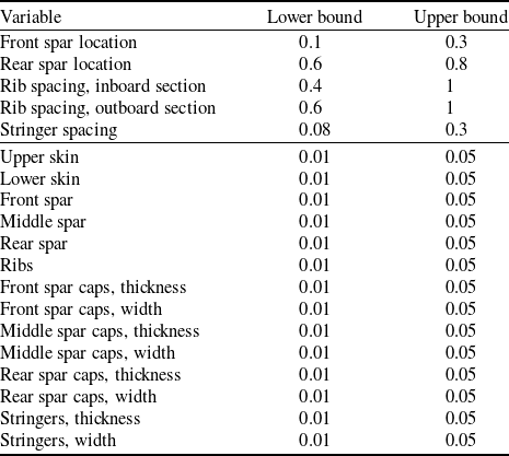
The design variables of the optimisation framework are grouped into geometric and thickness parameters. The geometric variables include the front and rear spar locations, expressed as a percentage of the local chord, the rib spacing in the inboard and outboard sections of the wing, defined relative to the span of each section, and the stringer spacing, expressed relative to the local chord.
The thickness variables correspond to the ply count of the ${0^ \circ }$
,
${0^ \circ }$
, ${90^ \circ }$
and
${90^ \circ }$
and $ \pm {45^ \circ }$
plies in each laminate and for each wing component. By setting the number of
$ \pm {45^ \circ }$
plies in each laminate and for each wing component. By setting the number of $ + {45^ \circ }$
and
$ + {45^ \circ }$
and $ - {45^ \circ }$
plies equal, symmetric and balanced lay-ups are obtained, thereby conforming to standard composite design guidelines [Reference Kassapoglou32]. For the beam elements, representing the front and rear spar caps as well as the stringers, the design variables are their respective widths and thicknesses.
$ - {45^ \circ }$
plies equal, symmetric and balanced lay-ups are obtained, thereby conforming to standard composite design guidelines [Reference Kassapoglou32]. For the beam elements, representing the front and rear spar caps as well as the stringers, the design variables are their respective widths and thicknesses.
A summary of all variables, including their lower and upper bounds and type, is given in Table 4. A horizontal line is used to separate geometric from thickness variables.
Optimisation variables bounds

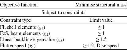
3.4 Objective function and constraints
The optimisation objective is the minimisation of the structural mass of the wing. Constraints were imposed on strength, stiffness, global linear buckling and flutter velocity, as outlined earlier. Strength requirements for the shell elements of the FEM model were evaluated using the Failure Index (FI) based on the Tsai–Wu criterion, while the strength of the beam elements was assessed using the maximum stress criterion.
Flutter instabilities were investigated for the first ten structural modes using both velocity-damping ( $V$
-
$V$
- $g$
) and velocity-frequency (
$g$
) and velocity-frequency ( $V$
-
$V$
- $f$
) plots. For each mode, the damping trends were monitored, with a change of sign indicating potential flutter onset. The flutter speed was then determined by linear interpolation between the two velocities bracketing the sign change in damping. If no flutter point was observed, the flutter velocity was set outside the analysed velocity range.
$f$
) plots. For each mode, the damping trends were monitored, with a change of sign indicating potential flutter onset. The flutter speed was then determined by linear interpolation between the two velocities bracketing the sign change in damping. If no flutter point was observed, the flutter velocity was set outside the analysed velocity range.
The overall optimisation problem setup is summarised in Table 5.
Optimisation problem summary

4.0 Results
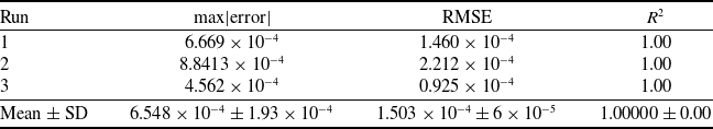
4.1 Surrogate model accuracy
In order to assess the accuracy of the surrogate model developed, the root mean square error (RMSE) and the coefficient of determination ( ${R^2}$
) were calculated using the training Design of Experiment (DoE) samples. These metrics quantify the average prediction error and the overall goodness of fit between the predicted (
${R^2}$
) were calculated using the training Design of Experiment (DoE) samples. These metrics quantify the average prediction error and the overall goodness of fit between the predicted ( ${\hat y_i}$
) and high-fidelity (
${\hat y_i}$
) and high-fidelity ( ${y_i}$
) responses. They are defined as
${y_i}$
) responses. They are defined as
 \begin{align}{\textrm{RMSE}} = \sqrt {{1 \over N}\mathop \sum \limits_{i = 1}^N {{( {{y_i} - {{\hat y}_i}} )}^2}} \end{align}
 \begin{align}{R^2} = 1 - {{\mathop \sum \nolimits_{i = 1}^N {{( {{y_i} - {{\hat y}_i}} )}^2}} \over {\mathop \sum \nolimits_{i = 1}^N {{( {{y_i} - \bar y} )}^2}}}\end{align}
where $N$
is the number of training samples and
$N$
is the number of training samples and $\bar y$
denotes the mean of the high-fidelity responses. An
$\bar y$
denotes the mean of the high-fidelity responses. An ${R^2}$
value approaching unity and a low RMSE indicate an accurate surrogate model representation of the underlying high-fidelity behaviour. The results are presented in Table 6.
${R^2}$
value approaching unity and a low RMSE indicate an accurate surrogate model representation of the underlying high-fidelity behaviour. The results are presented in Table 6.
Surrogate accuracy across three independent SBO runs

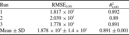
To further evaluate the generalisation capability of the surrogate model, a leave-one-out (LOO) cross-validation analysis was performed. In this approach, each sample in the DoE is temporarily excluded from the training set, and the model is reconstructed using the remaining $N - 1$
samples. The excluded point is then predicted, and the corresponding prediction error is recorded. The process is repeated for all
$N - 1$
samples. The excluded point is then predicted, and the corresponding prediction error is recorded. The process is repeated for all $N$
samples, providing a robust estimate of model accuracy independent of overfitting. The LOO RMSE (
$N$
samples, providing a robust estimate of model accuracy independent of overfitting. The LOO RMSE ( ${\textrm{RMS}}{{\textrm{E}}_{{\textrm{LOO}}}}$
) is computed as
${\textrm{RMS}}{{\textrm{E}}_{{\textrm{LOO}}}}$
) is computed as
 \begin{align}{\textrm{RMS}}{{\textrm{E}}_{{\textrm{LOO}}}} = \sqrt {{1 \over N}\mathop \sum \limits_{i = 1}^N {{( {{y_i} - {{\hat y}_{i,{\textrm{LOO}}}}} )}^2}} \end{align}
where ${\hat y_{i,{\textrm{LOO}}}}$
denotes the prediction obtained by excluding the
${\hat y_{i,{\textrm{LOO}}}}$
denotes the prediction obtained by excluding the $i$
-th sample from the training set. A low value of
$i$
-th sample from the training set. A low value of ${\textrm{RMS}}{{\textrm{E}}_{{\textrm{LOO}}}}$
, consistent with the RMSE computed on the full training data, indicates that the surrogate model exhibits high predictive accuracy and minimal overfitting. The computed values for the three independent SBO runs are summarised in Table 7.
${\textrm{RMS}}{{\textrm{E}}_{{\textrm{LOO}}}}$
, consistent with the RMSE computed on the full training data, indicates that the surrogate model exhibits high predictive accuracy and minimal overfitting. The computed values for the three independent SBO runs are summarised in Table 7.
Leave-one-out (LOO) cross-validation accuracy of the surrogate models

The LOO errors are consistent across runs, with a mean RMSE ${_{{\textrm{LOO}}}}$
of
${_{{\textrm{LOO}}}}$
of $1.878 \times {10^3}$
and
$1.878 \times {10^3}$
and $R_{{\textrm{LOO}}}^2 = 0.891 \pm 0.001$
. Given the scale of the response (wing mass
$R_{{\textrm{LOO}}}^2 = 0.891 \pm 0.001$
. Given the scale of the response (wing mass ${\mathcal{O}}({{{10}^4}})$
), these metrics indicate satisfactory predictive capability for preliminary structural sizing.
${\mathcal{O}}({{{10}^4}})$
), these metrics indicate satisfactory predictive capability for preliminary structural sizing.
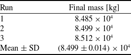
4.2 SBO robustness
The robustness of the developed SBO is also examined. In particular, three different SBO runs were performed, pertaining to different LHS seeds. The minimum feasible value of the objective function for each run is summarised in Table 8. In particular, all three runs converged to feasible designs with a mean optimal mass of $\left( {8.499 \pm 0.014} \right) \times {10^4}$
kg. The convergence behaviour of the cumulative best feasible value of the objective function for each individual run is illustrated in Fig. 6.
$\left( {8.499 \pm 0.014} \right) \times {10^4}$
kg. The convergence behaviour of the cumulative best feasible value of the objective function for each individual run is illustrated in Fig. 6.
Reproducibility of SBO results across three independent runs

Convergence history of the SBO framework for 3 independent runs.

4.3 Constraint feasibility and activity
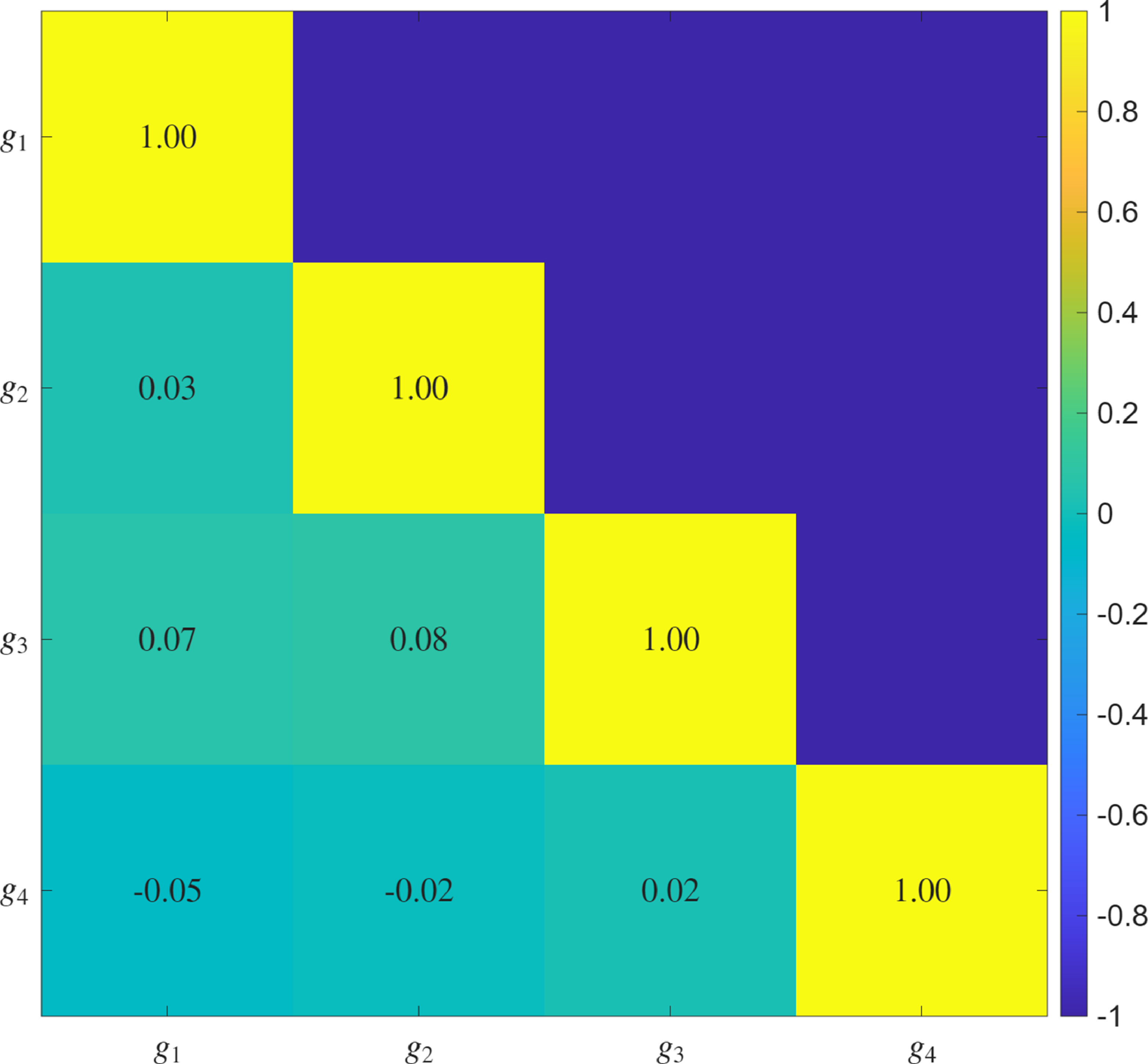
To better understand the interaction between constraints and their influence on the optimisation process, both the correlation structure and the activity level of all constraints were examined.
Figure 7 presents the Pearson correlation matrix between the constraint functions, evaluated over all sampled designs of SBO Run 1. The diagonal terms are equal to unity by definition, while the off-diagonal terms quantify the degree of linear dependency between constraint responses. A moderate correlation is observed between the shell failure index constraint ( ${g_1}$
) and the global buckling constraint (
${g_1}$
) and the global buckling constraint ( ${g_3}$
), indicating that configurations approaching stress limits also tend to approach buckling instability. This behaviour is physically consistent, since both constraints are governed by the stiffness distribution of the wing-box and the compressive load state induced by manoeuvre loading.
${g_3}$
), indicating that configurations approaching stress limits also tend to approach buckling instability. This behaviour is physically consistent, since both constraints are governed by the stiffness distribution of the wing-box and the compressive load state induced by manoeuvre loading.
Pearson correlation matrix of constraint functions.

In contrast, the flutter constraint ( ${g_4}$
) exhibits weak correlation with both strength and buckling constraints, suggesting that aeroelastic stability behaves largely independently within the explored design space. The beam factor-of-safety constraint (
${g_4}$
) exhibits weak correlation with both strength and buckling constraints, suggesting that aeroelastic stability behaves largely independently within the explored design space. The beam factor-of-safety constraint ( ${g_2}$
) also shows minimal correlation with the remaining constraints, reflecting its limited interaction with the dominant shell-driven structural mechanisms.
${g_2}$
) also shows minimal correlation with the remaining constraints, reflecting its limited interaction with the dominant shell-driven structural mechanisms.
Beyond correlation analysis, the frequency and intensity of constraint activity were investigated. Figure 8 illustrates both the satisfaction frequency and the normalised constraint margins across all sampled designs. The shell failure index ( ${g_1}$
) and global buckling constraint (
${g_1}$
) and global buckling constraint ( ${g_3}$
) exhibit the highest levels of activity, frequently approaching their admissible limits. This indicates that these two constraints actively shape the feasible design space and drive the structural sizing process.
${g_3}$
) exhibit the highest levels of activity, frequently approaching their admissible limits. This indicates that these two constraints actively shape the feasible design space and drive the structural sizing process.
Constraint satisfaction frequency (left) and normalised constraint margins (right) across all sampled designs.

In contrast, the flutter constraint ( ${g_4}$
) remains largely inactive, maintaining substantial positive margins across the majority of sampled configurations. Similarly, the beam factor-of-safety constraint (
${g_4}$
) remains largely inactive, maintaining substantial positive margins across the majority of sampled configurations. Similarly, the beam factor-of-safety constraint ( ${g_2}$
) displays consistently large safety margins, confirming that beam elements do not govern feasibility within the present design bounds.
${g_2}$
) displays consistently large safety margins, confirming that beam elements do not govern feasibility within the present design bounds.
The combined evidence from the correlation matrix and activity analysis demonstrates that the optimisation problem is primarily governed by shell-level strength and global stability considerations. The relatively low interaction of flutter and beam constraints further suggests that, within the examined design space and loading conditions, aeroelastic and beam strength requirements do not significantly restrict the attainable mass reduction. These observations are consistent with the constraint margins reported at the optimal design point and confirm that the SBO framework converges toward configurations controlled by physically meaningful structural drivers.
4.4 Design variable correlation with the objective function and constraints
To gain further insight into the structural drivers of the optimisation process, a correlation-based sensitivity analysis was performed between the design variables and both the objective function and the most active constraints. The Pearson correlation coefficients were computed using all sampled designs (DoE and infill points) generated during SBO Run 1.
Figure 9 presents the correlation coefficients between each design variable and the resulting wing mass. The observed trends are physically consistent. Specifically, variables that directly increase structural thickness exhibit a strong positive correlation with mass, while spacing-type variables (rib spacing and stringer spacing) show a negative correlation, since larger spacing reduces the number of structural elements and consequently the overall structural weight. The lower skin thickness exhibits the strongest positive correlation, followed by the rib and upper skin thicknesses, indicating that these components dominate the mass sensitivity within the explored design space. Beam-related variables display comparatively weaker correlations, reflecting their smaller contribution to total structural mass. Overall, this analysis clearly identifies the structural regions that govern mass variation and supports the physical consistency of the SBO exploration.
Pearson correlation coefficients of design variables with mass.

To better understand which structural responses govern feasibility, a similar analysis was conducted between all design variables and the two most active constraints: the failure index of shell elements ( ${g_1}$
), and the global linear buckling constraint (
${g_1}$
), and the global linear buckling constraint ( ${g_3}$
). As discussed in Section 4.3, these constraints exhibited the largest variation and most frequent activity throughout the feasible design space, indicating that they are the primary drivers of structural sizing.
${g_3}$
). As discussed in Section 4.3, these constraints exhibited the largest variation and most frequent activity throughout the feasible design space, indicating that they are the primary drivers of structural sizing.
For the shell failure index constraint ( ${g_1}$
), the correlation coefficients shown in Fig. 10 reveal strong negative correlations with skin thicknesses, rib thickness, spar thicknesses and spacing variables. This behaviour is fully consistent with classical bending and panel theory. Increasing skin or spar thickness enhances bending stiffness of the wing-box, thereby reducing stresses in primary load-carrying members and lowering the failure index. Similarly, reducing rib or stringer spacing decreases the effective unsupported panel length, increasing both bending and shear stiffness and improving strength margins. The consistency of these trends confirms that shell-level strength requirements significantly influence the structural sizing outcome.
${g_1}$
), the correlation coefficients shown in Fig. 10 reveal strong negative correlations with skin thicknesses, rib thickness, spar thicknesses and spacing variables. This behaviour is fully consistent with classical bending and panel theory. Increasing skin or spar thickness enhances bending stiffness of the wing-box, thereby reducing stresses in primary load-carrying members and lowering the failure index. Similarly, reducing rib or stringer spacing decreases the effective unsupported panel length, increasing both bending and shear stiffness and improving strength margins. The consistency of these trends confirms that shell-level strength requirements significantly influence the structural sizing outcome.
Pearson correlation coefficients of design variables with ${g_1}$
constraint.
${g_1}$
constraint.

For the global buckling constraint ( ${g_3}$
), the correlation results shown in Fig. 11 indicate that the strongest influences arise from the wing skins, ribs and rib spacing variables. These components are subjected to significant compressive stresses on the upper surface during manoeuvre loading. The negative correlations observed for thickness variables imply that increasing thickness enhances overall structural stiffness and suppresses global buckling tendencies. Likewise, reduced rib spacing improves panel stability by decreasing effective slenderness. These trends are consistent with classical plate and shell stability theory and confirm that stability considerations represent a dominant driver in the structural design of the high-aspect-ratio lifting surface examined.
${g_3}$
), the correlation results shown in Fig. 11 indicate that the strongest influences arise from the wing skins, ribs and rib spacing variables. These components are subjected to significant compressive stresses on the upper surface during manoeuvre loading. The negative correlations observed for thickness variables imply that increasing thickness enhances overall structural stiffness and suppresses global buckling tendencies. Likewise, reduced rib spacing improves panel stability by decreasing effective slenderness. These trends are consistent with classical plate and shell stability theory and confirm that stability considerations represent a dominant driver in the structural design of the high-aspect-ratio lifting surface examined.
Pearson correlation coefficients of design variables with ${g_3}$
constraint.
${g_3}$
constraint.

Although Pearson correlation captures only linear dependencies between variables and responses, the coherent physical patterns observed across all major structural components provide confidence that the dominant structural mechanisms are correctly identified within the explored design space. The results demonstrate that mass is primarily influenced by skin and rib thicknesses, while structural feasibility is governed mainly by shell strength and global buckling requirements, in agreement with the active constraints identified at the optimal design.
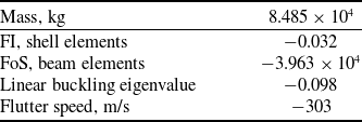
4.5 Structural response of the optimal configuration
The resulting mass of the wing at the optimal design point corresponds to $8.485 \times {10^4}$
kg. Convergence to a minimum mass, along with non-violated design constraints, was achieved at 250 iterations of the SBO algorithm. The corresponding mass and constraint values at the optimal design are provided in Table 9. The FI constraint of the shell elements (-0.032) and the linear buckling eigenvalue margin (−0.098) indicate that both strength and stability requirements were critical drivers in the final configuration. In contrast, the flutter constraint was satisfied with a substantial safety margin (−303), suggesting that aeroelastic stability did not significantly influence the optimum within the defined design space. The factor of safety for the beam elements exhibited a very large negative margin (
$8.485 \times {10^4}$
kg. Convergence to a minimum mass, along with non-violated design constraints, was achieved at 250 iterations of the SBO algorithm. The corresponding mass and constraint values at the optimal design are provided in Table 9. The FI constraint of the shell elements (-0.032) and the linear buckling eigenvalue margin (−0.098) indicate that both strength and stability requirements were critical drivers in the final configuration. In contrast, the flutter constraint was satisfied with a substantial safety margin (−303), suggesting that aeroelastic stability did not significantly influence the optimum within the defined design space. The factor of safety for the beam elements exhibited a very large negative margin ( $ - 3.963 \times {10^4}$
), primarily due to the use of the fiber-direction tensile strength of the Hexcel IM7/8552 composite material as the governing criterion. This led to highly conservative estimates for beam elements, which consequently did not participate in defining the active constraint set. Overall, the results demonstrate that the mass-optimal solution was governed by local panel failure and buckling considerations, while beam and aeroelastic constraints remained inactive.
$ - 3.963 \times {10^4}$
), primarily due to the use of the fiber-direction tensile strength of the Hexcel IM7/8552 composite material as the governing criterion. This led to highly conservative estimates for beam elements, which consequently did not participate in defining the active constraint set. Overall, the results demonstrate that the mass-optimal solution was governed by local panel failure and buckling considerations, while beam and aeroelastic constraints remained inactive.
Optimisation problem results summary

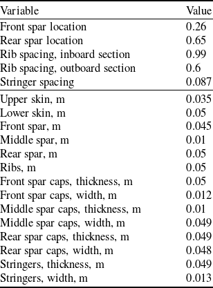
The design variables at the optimal point are presented in Table 10. The optimised design variables lie consistently near the upper bounds of the structural thicknesses and widths ( $ \approx $
0.045−0.05), suggesting that the load-carrying requirements favour stiffer and stronger components to satisfy stress and global buckling constraints. In contrast, the middle spar thickness converges close to the lower limit, implying its reduced structural role compared to the front and rear spars. The front spar location (0.26) and rear spar location (0.65) remain well within the feasible design space, providing an efficient internal load path. Rib spacing converges to its maximum inboard (
$ \approx $
0.045−0.05), suggesting that the load-carrying requirements favour stiffer and stronger components to satisfy stress and global buckling constraints. In contrast, the middle spar thickness converges close to the lower limit, implying its reduced structural role compared to the front and rear spars. The front spar location (0.26) and rear spar location (0.65) remain well within the feasible design space, providing an efficient internal load path. Rib spacing converges to its maximum inboard ( $ \approx $
1) but remains at the lower bound outboard (0.65), highlighting the trade-off between minimising weight and ensuring local stability. The stringer spacing is also at its minimum, reflecting the optimiser’s tendency to increase panel stiffening where required. Overall, the solution indicates that the optimiser exploited the full allowable ranges of key structural parameters, with thinner elements only where structurally permissible, leading to a weight-efficient yet constraint-compliant wing configuration.
$ \approx $
1) but remains at the lower bound outboard (0.65), highlighting the trade-off between minimising weight and ensuring local stability. The stringer spacing is also at its minimum, reflecting the optimiser’s tendency to increase panel stiffening where required. Overall, the solution indicates that the optimiser exploited the full allowable ranges of key structural parameters, with thinner elements only where structurally permissible, leading to a weight-efficient yet constraint-compliant wing configuration.
Optimisation variables summary

The structural response of the optimised wing was further assessed through global buckling, static deflection, beam stresses and composite shell FI distributions. The first global linear buckling eigenmode (Fig. 12) is localised in the inboard region, consistent with the high load transfer near the wing root. The associated eigenvalue is close to the imposed limit, which aligns with the near-active margin of −0.098 reported in Table 9, confirming buckling as one of the governing constraints of the optimisation. The static vertical deflection under design loading (Fig. 13) exhibits a smooth bending profile dominated by wing-box flexibility, with no evidence of local panel instabilities. The stress distribution in the beam elements (Fig. 14) highlights peak stresses in the spar caps at the wing root, where bending moments are highest, while the remainder of the structure remains lightly stressed, consistent with the large safety margin observed for beam elements. The maximum FI distribution (Fig. 15) shows localised high values in the skin and spar regions near the root and Yehudi break, typical of such structures. These results confirm that the optimised configuration satisfies all strength and stability requirements, with shell failure indices and global buckling emerging as the most critical design drivers, while beam stresses remain far from their allowable limits.
Optimal design – critical global buckling mode of the wing.

Optimal design – vertical deflection distribution of the wing [m].

Optimal design – maximum bending stresses distribution at the beam elements of the wing [MPa].

Optimal design – maximum FI distribution of the wing.

Having established that the structure is governed primarily by strength and global buckling considerations, the subsequent flutter analysis further demonstrates that aeroelastic stability does not impose additional restrictions within the operational flight envelope. In particular, the V-g and V-f plots at the optimal point are presented in Fig. 16. The damping characteristics show that all modes remain stable within the velocity range of interest, with no crossing of the zero-damping line. Modes IV and VII exhibit the lowest damping margins, gradually decreasing with increasing velocity, but do not reach instability within the investigated envelope. The corresponding frequency evolution indicates smooth trends with no abrupt coalescence phenomena, further confirming the absence of modal coupling that could trigger flutter onset. The consistently positive damping and monotonic frequency variation demonstrate that the optimised wing structure satisfies the aeroelastic constraint with a comfortable safety margin, as also reflected in the large negative flutter margin reported in Table 9.
Optimal design – (a) V-g and (b) V-f plots.

5.0 Conclusions
This work presented a fully parametric FEM and SBO framework for the structural design of high aspect-ratio composite wings. By integrating parametric geometry generation with SBO, the approach enables simultaneous variation of geometric and thickness design variables within a computationally efficient workflow. Application of the framework to a representative wing demonstrated convergence to a mass-optimal solution of $8.485 \times {10^4}$
kg, with global buckling and composite failure indices emerging as the critical active constraints. Beam element stresses and flutter requirements were satisfied with large safety margins, indicating that strength and stability governed the design, while aeroelastic constraints remained inactive within the analysed envelope.
$8.485 \times {10^4}$
kg, with global buckling and composite failure indices emerging as the critical active constraints. Beam element stresses and flutter requirements were satisfied with large safety margins, indicating that strength and stability governed the design, while aeroelastic constraints remained inactive within the analysed envelope.
The results confirm the capability of the proposed approach to identify structurally efficient designs while rigorously satisfying multidisciplinary constraints. Importantly, the framework provides clear insight into the relative influence of strength, global buckling and aeroelastic phenomena on the final configuration, which is valuable for guiding early-stage design decisions.
The limitations of the present study are primarily associated with the modeling assumptions adopted to enable efficient preliminary structural sizing and optimisation. In particular, global buckling constraints are enforced through linearised eigenvalue buckling analysis, which provides a global stiffness-based measure of structural stability and identifies critical bifurcation modes under proportional loading. While this approach is widely used at early design stages, it does not capture the inherently local and nonlinear nature of buckling phenomena in composite structures, nor the progressive or localised post-buckling behaviour that governs the true stability of individual panels, spars or skins. As such, buckling is treated in the present framework as a global constraint associated with overall structural stiffness, rather than as a detailed stability prediction tool. Similarly, composite strength constraints are evaluated using failure index-based criteria, such as the Tsai-Wu formulation, which are effective screening metrics but do not account for progressive ply damage, matrix cracking or delamination mechanisms. These modeling choices are appropriate for early-stage design and trade-off studies; however, more detailed nonlinear stability and failure analyses would be required in later design phases. Future work will focus on extending the proposed framework to incorporate increased fidelity in both structural and aerodynamic modeling while preserving the computational efficiency afforded by surrogate-based optimisation. On the structural side, this includes the integration of nonlinear buckling and post-buckling analyses, as well as geometric nonlinearity in static aeroelastic simulations. From an aerodynamic perspective, the coupling with higher-fidelity aerodynamic solvers, such as transonic potential-flow or RANS methods, would enable a more accurate representation of aerodynamic loads and aeroelastic phenomena in later design stages. Moreover, the inclusion of composite-specific design variables, such as laminate stacking sequence and tow-steering patterns, represents a promising avenue for enabling more advanced aeroelastic tailoring capabilities. Finally, the adoption of multi-fidelity surrogate modeling and uncertainty quantification techniques will be explored to efficiently combine analyses of varying fidelity levels, thereby enhancing the robustness of the optimisation process in the presence of modeling uncertainties and manufacturing variability.


 Open access