


Introduction
In recent years, a growing body of literature has focused on the debris structure and structural evolution of surge-type glaciers (e.g. Reference SharpSharp, 1985a, Reference Sharpb, Reference Sharp1988a, Reference Sharpb; Reference Lawson, Sharp and HambreyLawson and others, 1994; Reference LawsonLawson, 1996; Reference Glasser, Hambrey, Crawford, Bennett and HuddartGlasser and others, 1998; Reference Murray, Dowdeswell, Drewry and FrearsonMurray and others, 1998). This work has not only contributed to our understanding of the landform/sediment assemblage which results from glacier surges (e.g. Reference SharpSharp, 1988b; Reference BoultonBoulton and others, 1996; Reference Bennett, Hambrey, Huddart and GlasserBennett and others, 1999), but has also provided information about the strain history of glaciers during surge events, information vital for an understanding of the mechanisms responsible for surge-type behaviour (Reference Lawson, Sharp and HambreyLawson and others, 1994; Reference Murray, Dowdeswell, Drewry and FrearsonMurray and others, 1998). Reference SharpSharp (1985a, b) provided one of the first detailed models of the debris structure and structural evolution of a surge-type glacier, working at Eyjabakkajökull, Iceland. In particular, he recognized the importance of crevasse-filled ridges, formed by the deformation of basal sediment into subglacial crevasses (Reference SharpSharp, 1985a). “Crevasse-squeeze” ridges have been described at other surge-type glaciers (Reference ClappertonClapperton, 1975; Reference Solheim and PfirmanSolheim and Pfirman, 1985; Reference SolheimSolheim, 1991; Reference BoultonBoulton and others, 1996) and have become widely recognized as a potentially diagnostic landform of surge-type behaviour in the landform record (Reference SharpSharp, 1988b). This model of the structural evolution and debris structure of surge-type glaciers has been refined by subsequent work (e.g. Reference Hodgkins and DowdeswellHodgkins and Dowdeswell, 1994; Reference Lawson, Sharp and HambreyLawson and others, 1994; Reference Bennett, Hambrey, Huddart and GhienneBennett and others, 1996; Reference Hambrey, Dowdeswell, Murray and PorterHambrey and others 1996, Reference Hambrey, Bennett, Dowdeswell, Glasser and Huddart1999; Reference Glasser, Hambrey, Crawford, Bennett and HuddartGlasser and others, 1998).
Observations on the western margin of the surge-type glacier Skeiðarárjökull, Iceland (Fig. 1), in summer 1998 identified an additional form of debris-rich structure to those previously described on surge-type glaciers. Skeiðarárjökull last surged in 1991, and its surface is currently dominated by relict crevasses and supraglacial/englacial conduits which are infilled by partially deformed glaciofluvial sediment. This paper aims to: (1) document the morphology and sedimentology of these crevasse- and conduit-fill structures; (2) establish their relationship with other glaciological structures associated with the 1991 surge; and (3) examine their potential significance as indicators of subglacial hydrology.
Location map for Skeiðarárjökull. Structural traverses are labeled T1–T4.

Methods
The structural characteristics of the western margin of Skeiðarárjökull were documented along four 1 km transects orientated normal to the ice margin (Fig. 1). Data were recorded along each transect as follows: (1) the glacier profile was surveyed using an Abney level; (2) the dip and direction of dip of all structures within 5 m either side of each transect were recorded, along with their position on the transect; and (3) all debris-rich structures intersected by the transects were described and photographed, and all exposed sediments logged. In addition, typical examples of all the types of debris-rich structure on the western margin of Skeiðarárjökull were identified and documented in detail using a combination of tape surveys, photographs, scale-sketches and sediment logs.
Background: Skeiðarárjökull and the 1991 Surge
Skeiðarárjökull is located on the south side of Vatnajökull in southeast Iceland (Fig. 1). It surged in two distinct stages during spring and summer 1991 (Reference BjörnssonBjörnsson, 1998). In March, a surge front began to propagate down-glacier from a crevassed zone located approximately 10 km from the terminus, and by May a 50 m high surge front had reached the eastern glacier margin which subsequently advanced. In September, the second stage of the event commenced, when the western margin advanced by >1000 m (Reference BjörnssonBjörnsson, 1998).
Both stages of the surge were associated with reorganization of the subglacial hydrological system. The limited number of subglacial meltwater portals suggests that drainage is normally routed through large arterial tunnel systems within the glacier to the ice margin where it is discharged into the Súla and Skeiðará rivers (Fig. 1; Reference BjörnssonBjörnsson, 1998). During the surge, however, unusually turbid water emerged from numerous outlets along the glacier margin and through crevasses on the glacier surface (Reference BjörnssonBjörnsson, 1998). Using discharge data associated with the drainage of the subglacial lake Grímsvötn, both during and after the surge, Reference BjörnssonBjörnsson (1998) argued that the surge was associated with a switch from a subglacial tunnel system to one of linked basal cavities, following the ideas of Reference KambKamb (1987).
Much of the geomorphological expression of the 1991 surge was removed by the large jökulhlaup of November 1996. However, the section of ice margin around the Súla river has remained relatively undisturbed and the landform assemblage consists of two components, push moraines and out-wash fans. The push moraines are <10 m high, while each of the outwash fans has a surface gradient of 4–5° and consists of horizontally stratified granule-gravel and fine sand units, with occasional small scours and channels. The fans aggraded both during and after the formation of the push moraines, which contain tectonized fan sediments. Immediately behind the push-moraine and outwash-fan complex there is a 100–250 m wide zone of dead-ice topography.
Structural Glaciology
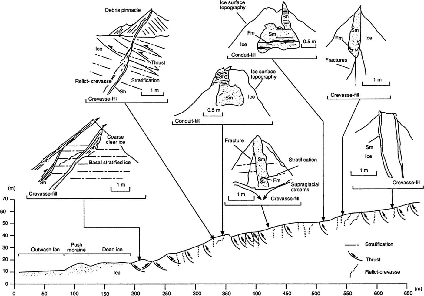
Part of one of the four structural traverses is shown in Figure 2, and the combined structural data from all four traverses are shown in Figure 3. The western margin of Skeiðarárjökull is covered by a thin surface veneer of sand and has an irregular surface topography of numerous debris pinnacles and ridges caused by differential ablation. Supraglacial drainage is minimal, as melt is quickly transferred via a network of moulins and englacial conduits towards the glacier bed. The following glaciological structures were recorded on the four traverses.
Structural traverse (T4) and field sketch of some of the debris-rich structures on the western margin of Skeiðarárjökull. Sh, horizontally stratified sand; Sm, massive sand; Fm, massive silt/clay.
Structural data collected along four structural traverses across the western margin of Skeiðarárjökull: (a) thrusts, (b) fractures, (c) crevasse traces, (d) crevasse fills. Glacier flow direction is based on the direction of maximum glacier slope.

1. Stratification
Two main types of ice stratification were observed. The first type was primary stratification formed by the accumulation of annual snow layers in the upper glacier basin. It was evident on the glacier surface as indistinct, sub-horizontal layers picked out by subtle variation in the bubble concentration within the ice and typically had an up-glacier dip of 14–35° with evidence of low-amplitude folding with the axes parallel to flow. The stratification was largely debris-free, although disseminated layers of tephra occur along the primary stratification in a few locations. The second type of stratification was associated with the surface outcrop of layers of debris-rich basal ice. Typically, these layers consisted of alternating bands of bubble-free, debris-poor ice and layers of debris-rich ice containing disseminated mud and granule-gravel clasts. This ice facies is similar in appearance to the “basal stratified suspended sub-facies ice” described by Reference LawsonLawson (1979) and Reference Lawson, Strasser, Evenson, Alley, Larson and ArconeLawson and others (1998).
2. Thrusts
Relatively low-angle fractures (25–65°) showing displacement of both primary and basal stratification are common on the glacier surface (Figs. 3a and 4). There are two main sets, one with up-glacier dips which are the more common, and a second set with down-glacier dips, restricted in outcrop to within 250 m of the glacier margin (Figs. 2, 3a and 4). Both sets are typically infilled with sediment that has the characteristics of glaciofluvial debris (sand and granule-gravel), which varies in thickness from as little as 0.5 cm to >350 cm. Other examples of low-angle fractures >1m thick, filled by diamicton, have been observed (Reference WallerWaller, 1997). The glaciofluvial sediment fills are either massive or, more commonly, horizontally stratified, with beds lying either parallel or sub-parallel to the fracture plane. In a few cases, there is an ice-facies change across the fracture, with “basal stratified suspended sub-facies ice” occurring on the up-glacier side and “englacial diffused-facies ice” on the down-glacier side (Reference Lawson, Strasser, Evenson, Alley, Larson and ArconeLawson and others’ (1998) terminology). The up-glacier-dipping fractures have both linear and arcuate outcrop traces 10–350 m long. These fractures are interpreted as debris-rich thrusts, by analogy with similar structures described elsewhere (cf. Reference Hambrey, Dowdeswell, Murray and PorterHambrey and others, 1996; Reference Murray, Gooch and StuartMurray and others, 1997). It is important, however, to note that displaced fractures may have a range of alternative origins; for example, displacement may occur across crevasses in icefalls or in thin ice moving over an irregular bed. However, the presence of basal stratified ice on the up-glacier side of some of the fractures described here suggests a scale of displacement which is more consistent with a tectonic (thrust) origin for the fractures.
Debris-rich thrusts within Skeiðarárjökull. (a) Close-up of a debris-rich thrust containing massive medium-to-coarse sand. Iceflow is from left to right. (b) Reverse thrusts containing horizontally stratified coarse sands with beds parallel to the thrust surface. Iceflow is from left to right.

3. Inclined fractures
A large number of planar and listric fractures with both up-glacier and down-glacier dips (25–65°) crop out on the glacier surface (Fig. 3b). They do not displace other structures. These fractures are normally closed and debris-free, although disseminated mud clots may occur along the fracture. Paired fractures, with sets dipping both down-glacier and up-glacier, are common.
4. Vertical/sub-vertical fractures
There are many partially closed or closed vertical and subvertical fractures (dips 80° and 90°) on the glacier surface, with outcrop traces 10–300 m long. These range from completely closed fractures, through open hairline fractures, to sediment-filled examples open to >1m. They show a range of strike orientations, although the mode is typically transverse to flow (Fig. 3c). In cross-section, individual fractures often bifurcate with depth and have an irregular form (Fig. 2). Many of the fractures contain infills of glaciofluvial sediments, and these structures are described in detail in the following section (Figs. 2 and 5). The fractures are interpreted as relict crevasses, which have been either closed, partially closed or infilled, but have not been completely sealed to form crevasse traces (cf. Reference Hambrey and MüllerHambrey and Müller, 1978).
The structures present on Skeiðarárjökull provide evidence of both longitudinal compression (thrusts) and extension (relict crevasses). The tectonic history is complex. In all observed cases, the thrusts and inclined fractures are crosscut by, and therefore pre-date, the vertical/sub-vertical fractures (relict crevasses). The development of thrusts with down-glacier dips is unusual (see Reference Hambrey, Dowdeswell, Murray and PorterHambrey and others, 1996, Reference Hambrey, Bennett, Dowdeswell, Glasser and Huddart1999). The occurrence of these structures close to the glacier margin, where longitudinal flow compression would have been greatest, is perhaps significant and they are tentatively interpreted as back-thrusts associated with intense shortening and thickening of relatively thin ice at the glacier margin (see Reference Boyer and ElliotBoyer and Elliot, 1982). This may have occurred immediately in front of the advancing surge front as it propagated towards the ice margin (see Reference Hambrey, Dowdeswell, Murray and PorterHambrey and others, 1996; Reference Murray, Dowdeswell, Drewry and FrearsonMurray and others, 1998). The stratified sediment infills within both the up- and down-glacier-dipping thrusts are not consistent with post-tectonic infill, although the massive fills could be. We interpret the stratified fills as the product of basal sediment entrainment prior to or during thrust formation by freezing-on of subglacial sediment (Reference BoultonBoulton, 1970, Reference Boulton, Price and Sugden1972).
Supraglacial Crevasse and Conduit Fills
The glacier surface contains a large number of linear and sinuous ice-cored ridges, which are draped by sand and granule-gravel. These ice-cored ridges are associated with dyke-like sediment bodies which penetrate into the glacier from its surface (Figs. 2 and 5). The meltout of these sediment dykes provides the sediment source for the formation of the ice-cored ridges. These ridges have a range of orientations, but are typically orientated either oblique or parallel to the glacier surface slope (Fig. 3d). There are two main types of structure: crevasse fills and conduit fills.
Supraglacial crevasse and conduit fills on the surface of Skeiðarárjökull. (a) Typical example of a crevasse fill, composed of granule-gravel, coarse sand, laminated silts. Note the vertical ice walls. (b) Crevasse fill of massive medium sand. Note the debris-free continuation of the infilled fracture in the distance, (c) Example of a crevasse-fill base. The structure is continued below the sediment fill by two prominent fractures/crevasse traces, (d) Two narrow and sub-parallel sediment fills, (e) The base of a crevasse fill containing deformed granule-gravel and coarse sand. Note the irregular fracture continuing the structure at the bottom lefthand corner (f) Typical conduit fill with a bifurcating multi-channelled or bifurcated base.

Crevasse fills
Crevasse fills typically form vertical or sub-vertical sediment dykes 0.05–1 m wide. These dykes penetrate from the glacier surface downwards along the vertical or sub-vertical fractures interpreted previously as relict crevasses (Figs. 2, 5 and 6). The vertical thickness of the individual fills is 1–3 m, although the original thicknesses prior to ice-surface ablation are unknown. Sediment infills are exclusively glacio-fluvial and range from massive units of coarse-to-medium sand in narrow fractures, to horizontally stratified, fine-to-coarse sand and granule-gravel, with silt interbeds, in wider fissures (Figs. 2 and 5). Laminated silts were also observed in several infills. The horizontally stratified units onlap the ice walls, and small channel or scour structures are occasionally present within the sediment fills (Fig. 6). The sedimentology within the crevasse fills is consistent with rapid sedimentation in a fluctuating-discharge regime (Reference KrügerKrüger, 1997); periodic episodes of low-energy water flow are responsible for the silt beds, while the scours represent periods of higher discharge. Pebble-gravel clasts are absent and units of granule-gravel are also relatively rare. There is little current ablation of the ice walls, which are normally vertical or sub-vertical (Figs. 2 and 5a–c). This implies that the crevasses infilled rapidly before water flow could result in ablation of the walls.
Scale sketch of a supraglacial crevasse fill. Sh, horizontally stratified sand; Sm, massive sand; Fm, massive silt/clay; FI, laminated silt/clay; GRm, massive granule-gravel.

At the base of each of the sediment dykes, there is one or more vertical or sub-vertical fractures (Fig. 5). Sediment does not infill these fractures, although they are often partially open (≤0.5 m). Others are sealed and resemble crevasse traces (Reference Hambrey and MüllerHambrey and Muller, 1978). Most of the infills show evidence of syn-sedimentary deformation at their stratigraphic base (Figs. 6 and 7), above which the successions are undeformed, except for post-sedimentary subsidence (small normal faults) associated with melting of the surrounding ice walls. A particularly good example of this type of succession is shown in Figure 6. At the base of the sediment fill, a series of irregular flame structures of silt and fine sand occurs within a matrix of massive medium- to-coarse sand (Fig. 7). This is overlain by massive sands and granule-gravels with occasional, irregular silt stringers. A prominent horizon of laminated silts within this part of the succession shows evidence, in the form of paired reverse faults, of both longitudinal and transverse bed-shortening. The upper part of the succession consists of undeformed, horizontally stratified, coarse sands and silts, with occasional channel scours. This type of gradation from a deformed succession at the base, to an undeformed series of beds at the top, is typical of the wider fracture fills observed by the authors. Sediment mixing is not a consequence of soft-sediment deformation induced by rapid sedimentation, since these features do not recur higher in the stratigraphic succession, despite similar grain-size variations. As a consequence, deformation is interpreted as having an external cause associated with closure of the surrounding ice walls. This is also consistent with the bed-shortening observed in some laminated silt units, and with the tightly folded sediments at the base of the crevasse fill shown in Figure 8.
Typical deformation facies at the base of a crevasse fill, consisting of irregular flames of silt and fine sand in a matrix of coarse sand and granule-gravel.

Cross-section through the deformed sediments at the base of a supraglacial crevasse fill. Lateral compression is a consequence of partial crevasse closure. Sh, horizontally stratified sand; Sm, massive sand; Fm, massive silt/clay; FI, laminated silt/clay; GRm, massive granule-gravel; GRh, horizontally stratified granule-gravel.

These structures are interpreted as glaciofluvial, supraglacial crevasse fills. Sedimentation of silt and sand infilled the base of partially closed or closing crevasses and continued after closure had ceased. There is little evidence for current ablation of the crevasse walls, which would have occurred had they been exposed to prolonged water flow. Consequently, rapid infilling and sedimentation is inferred (Fig. 5a). The discharge regime was pulsatory, with periods of quiet water deposition being represented by laminated silts. This pulsatory flow may reflect either variations in discharge (e.g. diurnal cycles) or changes in the continuity/connectivity of the drainage network.
Conduit fills
In contrast to the crevasse fills, conduit fills have arcuate basal cross-sections which are not associated with ice fractures (Figs. 2 and 5f). There are two basic morphological types. The first type consists of tubes which have been intersected from above by an open fracture (0.5–1 m wide). Both the tube and the fracture are infilled conformably with massive or horizontally stratified sand, silt and granule-gravel units (Fig. 2). These are interpreted as englacial conduits which have been intersected by crevasses penetrating from the glacier surface. Interestingly, crevasse penetration appears in most cases to have stopped when the englacial conduit was intersected. The second type of feature comprises vertical and sub-vertical slots, which may bifurcate with depth, and have channelled basal cross-sections (Fig. 5f). The ice walls show evidence of current ablation in the form of scoured and sculptured ice walls and have undergone lateral channel migration. These structures resemble the incised supraglacial channels present, on the current ice surface, both in cross-section and in planform. Both types of conduit fill contain a similar range of sedimentary facies—stratified sands, silts and granule-gravels—but unlike the crevasse fills, show no evidence of deformation.
Discussion
Structural glaciology
The structural characteristics of Skeiðarárjökull documented here are consistent with those reported from other surge-type glaciers (Reference SharpSharp, 1988b; Reference Lawson, Sharp and HambreyLawson and others, 1994; Reference Hambrey, Dowdeswell, Murray and PorterHambrey and others, 1996, Reference Hambrey, Bennett, Dowdeswell, Glasser and Huddart1999; Reference LawsonLawson, 1996; Reference Murray, Gooch and StuartMurray and others, 1997). There is evidence, in age order, of: (1) glacier compression (thrusts and inclined fractures), associated with the passage of the surge front through the glacier tongue; (2) glacier extension, immediately behind the surge front, which results in numerous crevasses; and (3) a final phase of small-scale glacier compression, associated with crevasse closure as the glacier entered its current post-surge quiescent phase.
There are two main types of debris-rich structure on Skeiðarárjökull: debris-rich thrusts and crevasse/conduit fills. The debris-rich thrusts are similar to those described from a range of surge-type and non-surge-type glaciers (Reference Hambrey, Dowdeswell, Murray and PorterHambrey and others, 1996,Reference Hambrey, Bennett, Dowdeswell, Glasser and Huddart1999) and probably involve the freezing-on of subglacial sediment, in this case of glaciofluvial sediment, prior to thrusting. The key observation here is the presence of occasional reverse thrusts, which dip down-glacier. These reverse thrusts are restricted to the extreme terminal zone and may represent some form of back-thrusting, associated with extreme longitudinal compression and shortening. Unlike other surge-type glaciers studied (Reference SharpSharp, 1985a, Reference Sharpb; Reference BoultonBoulton and others, 1996), “crevasse-squeeze” ridges formed by the deformation of subglacial sediment into basal crevasses appear to be absent, or have not yet been revealed by ablation. There is, however, extensive supraglacial infill of relict crevasses and conduits.
Origin of crevasse and conduit fills
Sedimentation within supraglacial channels and englacial conduits has been reported previously (e.g. Reference BoultonBoulton and others, 1989), as has the deformation of these sediments to produce flow-parallel debris structures (Reference SharpSharp, 1985b; Reference Bennett, Hambrey, Huddart and GhienneBennett and others, 1996; Reference Glasser, Bennett and HuddartGlasser and others, 1999). There is no doubt that sedimentation within surface channels, crevasses and conduits does occur and may give rise, on ablation, to structures similar to those described here, on a wide variety of glacier types. However, the observations reported above indicate that there is a single population of infilled crevasses and conduits on the western margin of Skeiðarárjökull with a uniform age structure, i.e. they date from a single episode of enhanced supraglacial drainage associated with the 1991 surge.
This inference is based on the following evidence. All the crevasse fills contain a similar sedimentary sequence, with deformed sediments at the base, overlain by undeformed sediments. The simplest explanation for this succession is that widespread crevasse closure occurred during an episode of supraglacial water flow and associated sedimentation. If the features had formed progressively at different times, the sedimentary succession would vary from one infilled crevasse to the next. This is not the case. The fact that there is no ablation, induced by water flow, on the crevasse walls indicates that sedimentation and water flow occurred simultaneously. The absence of ablation of the crevasse walls also supports the idea of a single episode of sedimentation. Extensive deposition within supraglacial channels is not commonplace on the glacier surface today and is, in general, restricted by the smooth channel walls in such settings. Finally, the structures do not cross-cut one another, which also supports the assertion that they formed as part of a single supraglacial drainage network, as opposed to a time-transgressive network.
It can also be argued that this episode of water flow occurred during the 1991 surge because: (1) the ice surface was too crevassed during the surge for the structures to predate it, and they show no evidence of having been crosscut by later structures associated with the surge, such as thrusts or fractures; and (2) the glacier has been largely quiescent since 1991, and is currently crevasse-free, with an integrated supraglacial/englacial drainage system in which sedimentation is limited. Enhanced supraglacial water flow did occur during the November 1996 jökulhlaup, but was restricted to supraglacial ice embayments above the main subglacial flood conduits, and cannot be invoked to explain the widespread occurrence of the crevasse and conduit fills described here from the western margin.
We conclude that the infilled crevasses and conduits represent an episode of enhanced supraglacial drainage, associated with very rapid sedimentation, towards the end of the 1991 surge when widespread crevasse closure was occurring. Reference BjörnssonBjörnsson (1998) described supraglacial outflow during the 1991 surge, which he interpreted as the product of subglacial dewatering via crevasses. We suggest that the glacio-fluvial crevasse and conduit fills described here are the physical manifestation of this process, and formed part of the channel system (notably the supraglacial component) feeding the numerous ice-marginal outwash fans associated with the surge front. Reference BjörnssonBjörnsson (1998) stated that water flowed from the bed upwards via crevasses. However, our observations suggest that most of the infilled crevasses did not penetrate to the glacier bed (Figs. 2, 5 and 8). The more likely water routing is therefore via the thrusts and associated fractures. One can envisage a scenario in which extensional glacier flow may have helped to open fractures formed during the initial compressive phase of the surge, thereby facilitating upward water flow. Equally, piping along debris-rich thrusts may also have opened up these structures as melt-water routeways and may also help explain the unusually turbid nature of the observed water (Reference BjörnssonBjörnsson, 1998). The absence of clasts larger than granule-gravel may partly reflect the discharge, but may also simply reflect sieving of the fluvially transported sediment by the fractures and thrusts. The sedimentary facies suggest that discharge was pulsatory, and this probably reflects fluctuations in subglacial water pressure (perhaps diurnal), and therefore the pressure gradient driving water towards the glacier surface. More prolonged periods of low-energy sedimentation in some of the sediment fills may reflect the changing continuity of the surface drainage network as crevasses or thrusts closed or opened. As the water emerged on the glacier surface, rapid sedimentation was likely following the fall in water velocity as it emerged from the fractures and thrusts.
The timing of this supraglacial discharge and associated sedimentation is provided by the evidence of syn-sedimentary deformation at the base of the fills, above which deformation is absent. This pattern of deformation suggests that sedimentation occurred first during crevasse closure and continued for at least a short time thereafter. Widespread crevasse closure is a common feature of the post-surge period as the glacier becomes quiescent (Reference SharpSharp, 1988b; Reference Lawson, Sharp and HambreyLawson and others, 1994; Reference LawsonLawson, 1996; Reference Glasser, Hambrey, Crawford, Bennett and HuddartGlasser and others, 1998; Reference Murray, Dowdeswell, Drewry and FrearsonMurray and others, 1998). This timing is also supported by evidence from the glacier forefield which indicates that the outwash fans accumulated both during and after the ice advance responsible for the marginal push moraines.
Significance of the crevasse and conduit fills
The observations of Reference BjörnssonBjörnsson (1998) support the idea that the episode of supraglacial drainage at Skeiðarárjökull during the 1991 surge was a function of changes in the glacier’s subglacial hydrology. The scale of the discharge, as indicated by the distribution of crevasse and conduit fills, as well as the absence of alternative supraglacial/englacial water sources, supports this idea. Unfortunately, our understanding of the subglacial hydrology of surge-type glaciers, and more specifically that of Skeiðarárjökull (Reference BjörnssonBjörnsson, 1998), is limited. It is not realistic, therefore, to develop meaningful numerical scenarios with which to examine the conditions necessary to produce such an episode of supraglacial drainage. Thus, what follows is a qualitative exploration of the potential mechanisms involved and their glaciological implications.
Reference BjörnssonBjörnsson (1998) has argued that the 1991 surge at Skeiðarárjökull was controlled by the development of a subglacial drainage network of linked cavities, following the ideas of Reference KambKamb and others (1985) and Reference KambKamb (1987). In this model, reorganization of the subglacial hydrological system, from an arterial to a linked-cavity system, causes a build-up of subglacial water pressure which facilitates rapid basal sliding and surge initiation. Return to an arterial system is prevented by rapid basal sliding, although the instability of the system ultimately allows an arterial network to become established, thereby terminating the surge (Reference KambKamb, 1987). At the close of the surge, stored subglacial meltwater is released as a flood event, as the arterial drainage system is restored (Reference Humphrey, Raymond and HarrisonHumphrey and others, 1986). The precise nature and form of the linked-cavity system at Skeiðarárjökull is unclear, since the geometry and character of the glacier bed are currently unknown. However, subglacial switching between some form of distributed drainage system and an arterial one appears to be the most likely cause of the periodic surges that affect Skeiðarárjökull, as argued by Reference BjörnssonBjörnsson (1998).
The development of supraglacial discharge may be linked to the build-up of subglacial water pressure within the linked-cavity system during the surge at Skeiðarárjökull. If the ice is relatively thin and highly fractured, this is not a surprising outcome (see Reference LiestølLiestøl, 1977; Reference KrügerKrüger, 1994; Reference Warburton and FennWarburton and Fenn, 1994; Reference Näslund and HassinenNäslund and Hassinen, 1996). In fact, supraglacial discharge occurred during the November 1996 jökulhlaup above the main subglacial flood conduits as a result of elevated subglacial water pressures. The widespread occurrence of supraglacial drainage over the whole of the western ice margin during the surge, as indicated by the crevasse fills, can therefore be viewed as a potential indicator of high subglacial water pressures. In turn, they may indicate the development of some form of distributed drainage system, such as a system of linked cavities.
As previously argued, the deformation structures at the base of the crevasse fills imply that water escape and supraglacial drainage was associated with the termination of the active phase of the surge. This raises the intriguing possibility that supraglacial drainage is implicated in the termination of the surge. As the glacier first develops a subglacial drainage system of linked cavities, the discharge of subglacial melt-water falls, due to the relative inefficiency of the linked drainage system (Reference KambKamb, 1987). Consequently, subglacial water pressures rise. As subglacial water pressures approach, and possibly exceed, ice-overburden pressure, enhanced sliding occurs, a process which accelerates as water pressure continues to rise (Reference KambKamb, 1987). During this phase of rapid flow, the glacier experiences longitudinal extension immediately behind the surge front (Reference Murray, Dowdeswell, Drewry and FrearsonMurray and others, 1998) and becomes highly crevassed and fractured. The exploitation of these fractures by pressurized subglacial meltwater could establish a drainage pathway between the glacier bed and its surface. As the water emerges on the crevassed glacier surface, rapid sedimentation occurs to give the crevasse and conduit fills. The development and evolution of this drainage pathway reduces subglacial water pressure, thereby decreasing the rate of subglacial sliding. As the rate of subglacial sliding falls, the potential for a return to an arterial subglacial drainage system increases (Reference KambKamb, 1987), a process which acts to terminate the active phase of the surge. As the surge ends, as a result of the fall in subglacial water pressure, the glacier ceases to extend and crevasse closure occurs, deforming the sediment fills. Continued sedimentation within the crevasses, following their initial closure, implies that the glacier had stopped actively extending, but that sufficient subglacial water pressure remained to maintain surface drainage. The final fall in subglacial water pressure, and thus the cessation of supraglacial water flow, may have occurred with the release of the stored subglacial water associated with the development of a fully integrated arterial drainage system (Reference Humphrey, Raymond and HarrisonHumphrey and others, 1986). It follows that the surge may have been first slowed/stopped by the supraglacial leakage of subglacial water, allowing an arterial drainage system to develop. The idea that a surge may be terminated by the leakage of subglacial water has been raised previously. For example, Reference Murray, Dowdeswell, Drewry and FrearsonMurray and others (1998) suggested that leakage may occur through subglacial sediments. Here we suggest that supraglacial water flow may also play a contributory role where the glacier is thin and highly fractured.
This scenario is not without problems, however. For example, the supraglacial release of subglacial water, and the associated reduction in the subglacial water flux, could actually help maintain, rather than destroy, the distributed drainage network, by reducing water pressure and therefore the drive towards an arterial system. The idea that a reduction in water pressure may help maintain a linked-cavity system is consistent with evidence from Variegated Glacier, Alaska, U.S.A., where the recent surge terminated in the early summer, associated with an increased subglacial water flux which appeared to have destabilized the linked-cavity system (Reference Humphrey, Raymond and HarrisonHumphrey and others, 1986). The answer to this lies in the delicate balance between (i) the rate of water flow to the glacier surface, (ii) the water pressure required to maintain sliding and therefore the linked-cavity system, and (iii) the upper threshold of water pressure, above which the linked-cavity system destabilizes. Such a complex balance is difficult to resolve when so many of the parameters are unknown at Skeiðarárjökull.
Given such alternative scenarios, the role of supraglacial drainage in terminating the surge remains speculative, but it is supported by the causality between widespread crevasse closure and the development of the supraglacial drainage pathway. Perhaps the critical point here is that the observations at Skeiðarárjökull emphasize the potential importance of supraglacial water leakage in thin glacier tongues, and its role in regulating subglacial water pressure. As such, it is a factor which may need considering in future models of the subglacial hydrology of surge-type glaciers.
Conclusions
Glaciofluvial crevasse and conduit fills result from the supraglacial infill of crevasses and conduits by surface drainage. This type of structure may form time-transgressively on a range of different types of glacier through conventional supraglacial drainage. However, the examples described here from Skeiðarárjökull belong to a single population formed during an episode of enhanced supraglacial drainage associated with the termination of the 1991 surge. The presence of deformation structures, consistent with crevasse closure, overlain by undeformed sediments within the crevasse fills, suggests that this episode of supraglacial drainage occurred at the end of the active phase of the surge and may therefore be partly implicated in its termination. The buildup of subglacial water pressure within a linked-cavity system during the surge allowed subglacial water to rise to the glacier surface, forming the crevasse and conduit fills. The leakage of subglacial water towards the glacier surface reduced subglacial water pressure and may therefore have helped terminate the active phase of the surge.
The occurrence of crevasse and conduit fills similar to those described here, on the surface of a glacier, may therefore provide evidence of elevated subglacial water pressures in certain situations. Such increased pressures may occur in the vicinity of a subglacial flood conduit during a jökulhlaup (Liestøl, 1976; Reference KrügerKrüger, 1994; Reference Näslund and HassinenNäslund and Hassinen, 1996), or due to the widespread elevation of subglacial water pressure during a surge, perhaps caused by changes in the nature of the subglacial drainage system. Where crevasse and conduit fills occur extensively over a glacier surface and show evidence of synchronous syn-sedimentary deformation, the latter explanation is more likely. As such, glaciofluvial crevasse and conduit fills are potentially important glaciological indicator structures, although the potential for their preservation is limited.
Acknowledgements
This work was funded by the University of Greenwich and Liverpool John Moores University. R.I.W. was funded by the Earthwatch 1998 project, “Icelandic Glaciers”, awarded to A.J. Russell, I. Fairchild, and P. G. Knight at the University of Keele, U.K. Constructive comments on various versions of this paper from N. Glasser are gratefully acknowledged.



