


1. Introduction
Manufacturing companies in the mechanical engineering sector increasingly extend their business models beyond the sale of standalone products by offering integrated customer solutions that combine machinery and services across the product lifecycle (Reference Lay, Copani, Jäger and BiegeLay et al., 2010). In the context of sheet metal working machine tools, this development manifests in networked multi-machine environments, digital service offerings such as remote operation support, and outcome-oriented business models like pay-per-part. These solutions are increasingly realised as cyber-physical systems of systems (CPSoS) and are developed iteratively using DevOps-inspired (Reference Jabbari, bin Ali, Petersen and TanveerJabbari et al., 2016) approaches to accelerate release cycles. This, in turn, raises demands on the internal engineering infrastructure, primarily regarding methods, processes, data management, and IT-systems.
Two consistency challenges become critical: first, ensuring traceability and coherence of product-related data across all lifecycle phases; and second, aligning this data with business strategy and processes, and with the application landscape. Product lifecycle management (PLM) addresses the former by maintaining a digital thread that enables traceability, reuse, and consistency of artefacts across the lifecycle (Reference Zehbold, Fend and HofmannZehbold, 2024). Enterprise architecture (EA) addresses the latter by providing principles and models to align business goals, processes, applications, and technology (Reference Lankhorst and LankhorstM. M. Lankhorst, 2017) (see Figure 1). However, existing approaches typically treat PLM and EA in isolation or apply them only to specific aspects of the engineering lifecycle. As a result, industrial practice is often characterised by fragmented data structures, heterogeneous toolchains, and limited transparency across engineering, IT, and business perspectives. These shortcomings are amplified in the engineering of CPSoS, where short DevOps-like development cycles must coexist with long physical product lifecycles and cross-generational reuse of engineering artefacts.
To address this gap, this paper proposes a PLM Architecture Framework, understood as an Enterprise architecture framework (EAF) approach tailored to PLM-related phases in engineering of sheet metal machine tools. The framework integrates model-based PLM representations and formalised consistency relations with principles from established Enterprise architecture frameworks, particularly TOGAF. Its objective is to provide a structured and consistent description of relevant elements and their relationships across the DevOps-inspired lifecycle, thereby supporting traceability of product-related data and alignment with business and IT perspectives.
Successful PLM of CPSoS requires consistency of product-related data (digital thread) as well as consistency between business goals, PLM processes and application landscape (aligned EA)

Figure 1 Long description
A diagram representing the integration of cyber-physical systems of systems (CPSoS) in the mechanical engineering sector. The diagram is divided into several sections, each illustrating different aspects of the process. On the left side, there are components related to the engineering of CPSoS, including MBSE, ECAD, MCAD, Software, and Simulation & Testing. These components feed into the central DevOps cycle, which includes stages such as Plan, Code & Design, Build, Test Automation, Release, Deploy, Monitor, and Remote Operation Support. The digital thread is highlighted as a continuous loop within this cycle. On the right side, the diagram shows the alignment of enterprise architecture (EA) with strategy & business goals, customer solutions, and applications. This section includes elements such as Strategy & Business Goals, Customer Solution (CS), Aligned EA, PLM Process, RE for CS, and Applications. The diagram emphasizes the importance of consistency in product-related data (digital thread) and the alignment between business goals, PLM processes, and the application landscape.
2. State of research
2.1. Product data and consistency relations in the PLM of complex systems
PLM is a holistic organizational approach for managing product-related information and processes to ensure the availability of the right information in the right context at the right time (Reference Ameri and DuttaAmeri & Dutta, 2005; Reference Zehbold, Fend and HofmannZehbold, 2024). A central concept in contemporary PLM is the digital thread, which describes the continuous linkage of product-related data across lifecycle phases to enable traceability, reuse, and configuration management (Reference EignerEigner, 2021; Reference StarkStark, 2022). In particular, the use of digital twins, e.g., as virtual prototypes, supports the digital thread concept by providing stakeholders with tailored, product-related data, and information at the right level of detail (Reference Schleich, Dittrich, Clausmeyer, Damgrave, Erkoyuncu, Haefner, Lange, Plakhotnik, Scheidel and WuestSchleich et al., 2019). An approach that is particularly relevant to cope with increasing system complexity and the need for data consistency is Model-based systems engineering (MBSE). It replaces document-centric practices with interconnected system models that integrate requirements, system architectures, CAD models, and software artefacts as partial models (Reference EignerEigner, 2021).
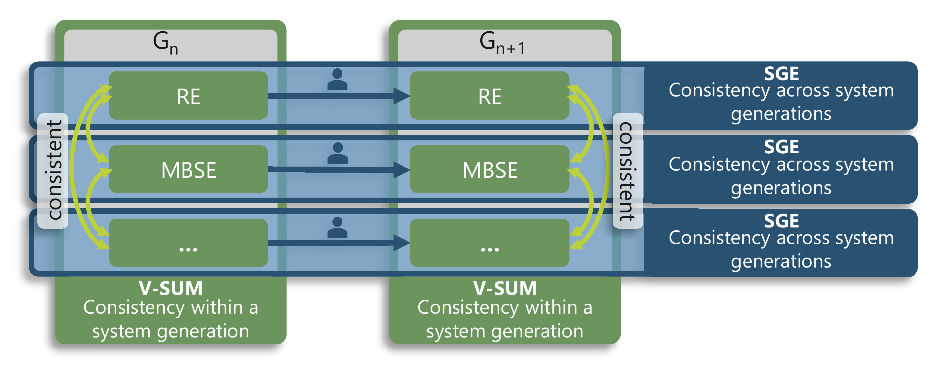
For complex systems such as machine tools, consistency must extend beyond a single generation. The model of SGE – system generation engineering highlights that new system generations rarely emerge from scratch; rather, they are developed based on a reference system through the activities of carry-over, attribute, and principle variation (Reference Albers, Rapp, Krause and HeydenAlbers & Rapp, 2022; Reference Albers, Rapp, Spadinger, Richter, Birk, Marthaler, Heimicke, Kurtz and WesselsAlbers et al., 2019). Changes applied in one generation can create dependencies and deltas that propagate across generations, making documentation and management of cross-generational consistency relations essential (Reference Albers, Schaefer, Gesmann, Ochs, Fischer, Pett, Schwarz, Krause, Paetzold and WartzackAlbers et al., 2024).
Current research provides first integrative approaches for consistency preservation. The Virtual Single Underlying Model (V-SUM) is a metamodel-based approach that combines partial models within a system generation and aims to reduce inconsistencies (Reference Klare, Kramer, Langhammer, Werle, Burger and ReussnerKlare et al., 2021). Recent work proposes combining V-SUM with the model of SGE to explicitly track cross-generational relationships and reduce inconsistencies across generations (Reference Albers, Schaefer, Gesmann, Ochs, Fischer, Pett, Schwarz, Krause, Paetzold and WartzackAlbers et al., 2024). Figure 2 illustrates this complementary function in the field of sheet metal working machine tools.
While these approaches provide strong methodological foundations, their operationalisation in industrial environments remains limited due to heterogeneous toolchains, incompatible metamodels, and missing architectural embedding across lifecycle phases and organisational domains. Additionally, short DevOps-like release cycles conflict with long physical product lifecycles. Here, the challenge is to check changes for consistency without slowing down development.
Ensuring consistency among models within a system generation through V-SUM, as well as across different generations of models using the model of SGE, adapted from Reference Albers, Schaefer, Gesmann, Ochs, Fischer, Pett, Schwarz, Krause, Paetzold and WartzackAlbers et al. (2024)

In summary, existing research addresses consistency either within or across system generations but lacks a comprehensive architecture concept that integrates product-related models, consistency relations, and enterprise-wide IT and process structures.
2.2. Enterprise architecture frameworks for consistent alignment of business and IT
While PLM focuses on the consistency of product-related data, enterprise architecture (EA) provides a complementary perspective by aligning business strategy, processes, applications, data, and technology within an organisation (Reference Foorthuis, van Steenbergen, Brinkkemper and BrulsFoorthuis et al., 2016; Reference Lankhorst and LankhorstM. M. Lankhorst, 2017; Reference SuhariSuhari, 2024). Enterprise architecture frameworks (EAFs) offer methodological guidance for architecture model development and structural templates, such as content frameworks, for describing and managing artefacts as well as their relationships within an enterprise architecture (Reference ZiemannZiemann, 2022).
Among widely used EAFs, The Open Group Architecture Framework (TOGAF) is particularly prominent in both research and industrial practice (Reference Cameron and McMillanCameron & McMillan, 2013; Reference Dumitriu and PopescuDumitriu & Popescu, 2020; Reference Santos, Ribeiro, Santos, Junior and RodriguesSantos et al., 2020). As illustrated in Figure 3, the content framework of TOGAF categorises architecture artefacts mainly into the following four core domains - Business Architecture, Data Architecture, Application Architecture, and Technology Architecture (The Open Group, 2025).
Four core architecture domains of TOGAF containing artefacts describing an enterprise architecture, based on The Open Group (2025)

The Business Architecture comprises business strategy, governance structures, organizational form, and core business processes. Data Architecture encompasses the logical and physical structure of an organization’s data assets and the associated resources for data management. Application Architecture is defined as a comprehensive plan that illustrates the deployment, interactions, and relationships of all relevant applications within an organization. Finally, Technology Architecture maps the organization’s digital infrastructure that defines the logical software and hardware structure, along with the underlying technical capabilities and standards (The Open Group, 2025). All these structured artefacts can then be utilised in a metamodel, for instance in the TOGAF Core Enterprise Metamodel, providing a consistent and traceable model template for EA descriptions (The Open Group, 2025).
Research has explored the existence of papers using EA principles in PLM-related contexts, such as IT system alignment and assessment (Reference Rigger, Vosgien, Bitrus, Szabo and EynardRigger et al., 2022), MBSE integration and design automation (Reference Vosgien, Rigger, Schwarz, Shea, Ríos, Bernard, Bouras and FoufouVosgien et al., 2017), systems development (Reference Sjöberg, Kihlström and HauseSjöberg et al., 2017), and ensuring data consistency between cyber-physical systems and manufacturing execution systems (Reference Aldea, Iacob, Wombacher, Hiralal and FranckAldea et al., 2018). However, these contributions typically address isolated aspects of the PLM landscape and do not provide a holistic architectural framework across the entire product lifecycle.
Consequently, despite the maturity of PLM methodologies and EA frameworks, a gap remains in systematically combining both perspectives to support consistency across lifecycle phases, organisational domains, and system generations in the engineering of CPSoS within a single framework.
3. Aim of research and research design
The aim of this research is to develop a PLM Architecture Framework that supports consistency in the engineering of machine tools by addressing two complementary challenges: (i) ensuring traceability and consistency of product-related data across the lifecycle of CPSoS, and (ii) aligning PLM-related processes, applications, and data with business goals and strategy. The framework builds on principles from enterprise architecture frameworks (EAFs), particularly TOGAF, and adapts them to the specific requirements of PLM in machine tool engineering. Based on this objective, the following research questions are addressed:
-
RQ1: What are requirements for a PLM Architecture Framework to support consistency in the engineering of machine tools?
-
RQ2: How can a PLM Architecture Framework be designed, based on existing EA frameworks, to meet the identified requirements?
The research follows the Design Research Methodology (DRM) by Reference Blessing and ChakrabartiBlessing and Chakrabarti (2009).
To answer RQ1, a Descriptive Study I was conducted in the form of a semi-structured expert interview study with stakeholders involved in the engineering of machine tools. The interviews focused on participants’ roles, experiences with PLM architectures and frameworks, and their expectations and requirements for a PLM Architecture Framework. A total of 15 interviews were conducted with representatives from different stakeholder groups. The interviews were anonymised, transcribed, and analysed using qualitative content analysis according to Reference Kuckartz and RädikerKuckartz and Rädiker (2024). Based on the identified requirements, four personas were developed using the qualitative persona method (Reference Jansen, Jung, Salminen, Guan, Nielsen and BuiJansen et al., 2021). Additionally, these requirements are grouped into three final subcategories that provide the foundation for the conceptualized PLM Architecture Framework.
To answer RQ2, a Prescriptive Study was conducted in which the identified requirements were systematically mapped to elements of existing EA frameworks, particularly the architecture domains defined in TOGAF. Where necessary, additional elements were introduced to address PLM-specific and lifecycle-spanning requirements. The resulting PLM Architecture Framework consists of multiple interlinked PLM Architecture Views along a DevOps-inspired lifecycle. One of these views is implemented and evaluated exemplarily in a requirement engineering case study at a machine tool manufacturer, which is presented in the following chapters.
4. Identifying requirements for a PLM architecture framework in the engineering of machine tools
4.1. Research methodology for the interview study and persona creation
Based on the state of research, relevant stakeholder groups in the ecosystem of engineering machine tools were identified. 16 interview candidates were selected with support from an internal PLM architecture expert to ensure broad representation of roles. In total, 15 interviews were conducted, including process owners (S1, S3, S4, S6), PLM architects (S5, S7, S15), product architects (S2, S10, S11, S12, S14), a product portfolio architect (S8), a software portfolio architect (S9), and the CTO (S13). The interviews lasted on average 30 minutes, were recorded with consent, anonymised, and transcribed for analysis. A semi-structured interview guide ensured consistency while allowing flexibility for individual perspectives. Key questions addressed the interviewees’ role, experience with PLM architectures, frameworks, and their requirements for such a PLM Architecture Framework.
The analysis of the transcripts followed the qualitative content analysis method by Reference Kuckartz and RädikerKuckartz and Rädiker (2024), which supports iterative deductive-inductive category development and actively incorporates the use of software. In this study the transcripts were analysed using the software MAXQDA. Initially, two deductive high-level categories – PLM architecture requirements and stakeholder role – were defined and complemented with one inductive main category capturing stakeholder pain points . Within the main category PLM architecture requirements , three subcategories emerged: (1) main conditions for representing the framework, (2) purpose of the framework, and (3) architecture domains.
The synthesis revealed shared and role-specific expectations regarding requirements for a PLM Architecture Framework. On this analytical basis, and using the qualitative persona method (Reference Jansen, Jung, Salminen, Guan, Nielsen and BuiJansen et al., 2021), four personas were developed to represent typical stakeholder perspectives and their complementary requirements for a PLM Architecture Framework. The perspectives of the resulting personas, along with the three developed requirements subcategories, provide a profound foundation for conceptualizing a PLM Architecture Framework in the engineering of machine tools.
4.2. Resulting requirements formalised in two personas and three subcategories
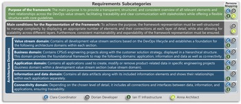
To answer RQ1, the identified requirements for a PLM Architecture Framework in the engineering of sheet metal working machine tools are illustrated through four personas: Anna Architect, Ian IT Infrastructure, Clara Coordinator, and Dorian Developer. The latter two are presented in detail as examples (see Figure 4). The requirements for a PLM Architecture Framework derived from the personas are then mapped and consolidated into the three subcategories (see Figure 5).
Different perspectives on a PLM Architecture Framework, represented by two personas

All four personas emphasise the need for a transparent, consistent and structured overview along the DevOps value stream. However, their expectations differ: While Clara Coordinator sees the framework as a holistic and strategic communication instrument aligned with business strategy across the entire DevOps value stream, Dorian Developer requires a detailed representation of elements and their connections within or between specific sections of the value stream. Further, Ian IT-Infrastructure, who is responsible for establishing an end-to-end IT infrastructure, requires a business- and process-related overview of the DevOps value stream to efficiently align the IT infrastructure with the necessary applications and their interfaces. Lastly, Anna Architect formulates framework requirements from a development perspective. She needs a framework that captures and describes all relevant elements and their connections in an intuitive, consistent easily maintainable manner, enabling clarity and adaptability.
The requirements identified for all four personas can be mapped onto the three subcategories (see Figure 5). The subcategories form the initial foundation for the conceptualization of the PLM Architecture Framework. In particular, the requirements placed on the framework regarding which elements it should include, organised within the subcategory architecture domains , are crucial for the framework’s structure.
Requirement subcategories and mapped personas as a basis for the conceptual PLM architecture framework

5. A PLM architecture framework for consistency in the engineering of machine tools
Building on these results, this chapter answers RQ2 and outlines how the initial concept of the framework was developed and how it was applied in a requirement engineering (RE) case study at the machine tool manufacturer.
5.1. Methodology for initial conceptualization of a PLM architecture framework
To translate the identified requirements into a first framework concept, the four architecture domains from the TOGAF EAF (see Figure 3) provided an appropriate baseline for organizing architecture elements relevant to PLM. These domains were adopted as reference domains for all defined domains within the subcategory of architecture domains , excluding the value stream domain (see Figure 5). Since this specific view is not explicitly covered by TOGAF, the introduction of the value stream domain into the framework ensures a holistic view across the entire DevOps lifecycle for the engineering of CPSoS, in which PLM processes and product-related data are considered in their respective sections.
The initial framework concept was iteratively refined in a collaborative manner. Through participation in workshops and project meetings as part of the requirements engineering case study, architecture elements were identified, reviewed, and further adapted based on stakeholder’s feedback. This iterative co-creation approach ensured that the emerging PLM Architecture Framework reflected practical needs, terminology, and real-world constraints. The outcome of this phase was a first operationalised version of the framework, ready to be applied in the case study.
5.2. Implementing PLM architecture framework in a RE case study
The case study focused on the introduction of a new requirements management (RM) application for engineering machine tools. Before scaling the application across the organization, it was piloted in a cross-product engineering project – a modular robot platform that provides an automated sorting solution for different sheet metal machine tools. This pilot project was selected for the case study because of its high requirements complexity, caused by strong interdependencies with multiple engineering projects, and collaboration with an external development partner.
The PLM Architecture Framework was applied to create a consistent and transparent PLM Architecture View that addressed the key questions raised by project stakeholders: (i) How can the new RM application best fulfil the specific requirements of the pilot project? (ii) Which architecture elements and their relationships are needed for a consistent RM across projects? (iii) How should the RE process and collaboration with the external partner and internal engineering teams be structured?
Figure 6 illustrates the resulting high-level PLM Architecture View for the pilot project. It integrates all five architecture domains: value stream, business, application, information & data, and connectivity. It visualises how the corresponding elements and their relations form a consistent view. Since the case study deals with the requirements management of engineering projects, the DevOps value stream section ‘Plan’ is examined in detail as an element within the value stream domain. Further the value stream domain marks the baseline for the following domains in developing an Architecture Framework View.
Integration of all architecture domains result in the PLM architecture view (center) that displays a structured and emergent traceability between all architecture elements

As previously mentioned, the business domain provides the structural basis for the framework representation, which projects are examined in detail and how these are related to each other (see Figure 6). In the context of the requirements engineering (RE) case study, all projects that have a link to the pilot project as a so-called intertechnology platform are displayed. In this case, the pilot project has a link at the higher strategic level to two specific customer solutions (CS) and, at the engineering level of machine tools, to two engineering projects and finally to the external partner. Based on this organizational structure of projects, the following domains can be represented, allowing for consistent transparency regarding which applications, data, and information are handled in each project.
According to the applications used in the case study, the application domain contains the RM application and Excel (see Figure 6). Excel is also considered here, as according to the project leaders of the pilot project, the exchange of the collected requirements with the external partner is to take place via an Excel export. Furthermore, the application domain displays the data elements that are handled in each application, represented as black boxes. Inside the requirements management (RM) application, it is observable that stakeholder requirements (SR) are linked with technical requirements (TR) in an n:m logic. With the following information and data domain, a more detailed view of the information elements contained in specific data type elements is presented (see Figure 6). The level of detail reveals that the link between the information elements SR and TR is not only an n:m derivation but also a traceability link that connects the original SR on which the current TR is based. Additionally, further information about the SR/TR is revealed by tags such as the origin of the predecessor project (pink) for SR and the target project (purple) for SR/TR. The status of the SR, indicate when it can be derived into a TR. Based on the level of detail, the connectivity domain displays not only the interfaces between the observed applications but also the relationship between data and information elements within an application across the observed projects (see Figure 6 and Figure 7).
Figure 7 illustrates the integration of all domains into the PLM Architecture View, enabling an emergent traceability between all observed elements. It also shows a digital thread linking to a subsequent PLM Architecture View ‘Code & Design’, which is treated as a partial black box. The PLM Architecture View provides stakeholders with a shared picture of which data and information assets, tools, business goals, and development activities are linked and how changes propagate across them. Building on this Architecture View, the requirements engineering (RE) process was modelled and aligned with the involved responsibilities, and system interactions (see Figure 7). The responsibilities for the pilot project, which demand an overall view of all involved projects, reflect the requirements of the persona Clara Coordinator. The remaining engineering project roles are represented by Dorian Developer and require a detailed, traceable view of data and information at a detailed engineering project level.
The eight displayed RE process steps, covering the flow from initial stakeholder requirements, through refinement and consolidation in the pilot project, to the derivation of technical requirements (TR) and the derivation of tasks. It shows the collaboration loops between the internal project teams and the external development partner, ensuring clarity on handovers, validation responsibilities, and traceability.
The PLM Architecture View combines the structure of the examined elements and their relationships with the RE process, along with the corresponding responsibilities

Figure 7 Long description
Panel A: The diagram shows the PLM Architecture View in the value stream section labeled Plan. It includes various elements such as containers, black box elements, information elements, and links. The diagram is divided into sections for the Intertechnology Platform: Pilot Project, External Partner, and Engineering Projects. Each section contains RM Applications and various data types like SR and TR. The flow of information and responsibilities among these elements is depicted with arrows and labels indicating the status and origin of SRs. Panel B: The diagram illustrates the Requirements Engineering Process, divided into Engineering Project and Pilot Project sections. It outlines steps such as tagging SRs, filtering, transferring, creating new SRs, switching status, deriving TRs, and assigning tasks. Responsibilities for product managers, pilot projects, and engineering teams are indicated with specific icons.
Applying the PLM Architecture Framework in the case study enabled the project team to answer the three guiding questions by providing a possible representation of the target architecture. The PLM Architecture View served as a transparent communication basis in discussions with stakeholders, making previously implicit knowledge on RM processes, roles, tools, and data connections explicit, consistent, and accessible. This improved shared understanding supported alignment across projects as well as with the external partner and enhanced decision-making regarding RM tool configuration and future roll-out.
6. Discussion, conclusion and outlook
The PLM Architecture Framework introduced in this paper integrates EA principles in a PLM-related context along an adapted DevOps lifecycle to ensure consistent and transparent management of product-related data. It aligns engineering domains with business strategy, goals, processes, and the application landscape, thereby supporting the realization of a digital thread for machine tool development as a backbone for traceability and data consistency across the lifecycle. This framework should not only be applicable to the domain of sheet metal working machine tools but also, after further validation, to enterprises manufacturing complex cyber-physical systems of systems (CPSoS) more generally.
Nevertheless, this research has limitations. First, the framework has so far been evaluated only through a single-case study within the ‘Plan’ section of the value stream domain. While the implementation yielded positive results, broader application across additional value stream sections is required to validate generalisability. Second, the architecture representations were not modelled using a standardised notation such as ArchiMate or UML. This may lead to inconsistencies in interpretation and reduce transferability to organisations relying on formalised EA modelling languages.
Furthermore, this study addressed two key questions: identifying requirements for a PLM Architecture Framework that supports consistency in machine tool engineering and the design of such a framework. The resulting conceptual framework shall offer a baseline for structuring relevant elements within the five developed architecture domains, resulting in transparent PLM Architecture Views in every required value stream section, with the aim of enabling a holistic interlinked PLM representation of the entire DevOps-inspired lifecycle (see Figure 8).
PLM architecture framework vision consisting of multiple PLM architecture views

Future work on extending the framework with additional PLM Architecture Views will further validate its applicability and scalability. Methodological refinement will focus on defining modelling guidelines, roles, and lightweight procedures to support iterative architecture evolution without administrative overhead. Integrating the framework into existing PLM, MBSE, and EA practices could allow organisations to better align toolchains, data flows, and engineering processes across disciplinary boundaries.
A long-term challenge remains the cross-generational management of engineering artefacts and their consistency relations. To address this, the Virtual Single Underlying Metamodel (V-SUM) introduced in Section 2.1 may offer a promising complementary approach. By harmonising engineering data and artefacts via consistency relationships between metamodels, V-SUM aims to enable a persistent digital thread across system generations – without requiring additional modelling effort through a central, monolithic system model.
Acknowledgement
This work is funded by the Deutsche Forschungsgemeinschaft (DFG, German Research Foundation) – CRC 1608 – 501798263.





 Open access

