Introduction
The organisation of minerals based on their structural and chemical properties is central to the field of Mineralogy. In recent years, work has focused on developing structure hierarchies for mineral groups previously classified on the basis of chemical composition. In mathematical terms, a hierarchy is an ordered set of elements where the ordering reflects a natural hierarchical relation between the arrangements of elements. In mineralogical terms, a structure hierarchy is a set of structures ordered according to the polymerisation of coordination polyhedra of higher bond-valence (Hawthorne, Reference Hawthorne1983a, Reference Hawthorne2014) from lower to higher connectivity. Structure hierarchies have been developed for phosphates, arsenates and vanadates (Kostov and Breskovska, Reference Kostov and Breskovska1989), phosphates (Hawthorne, Reference Hawthorne1998; Huminicki and Hawthorne, Reference Huminicki, Hawthorne, Kohn, Rakovan and Hughes2002), arsenates (Majzlan et al., Reference Majzlan, Drahota, Filippi, Bowell, Alpers, Jamieson, Nordstrom and Majzlan2014), vanadium bronzes (Evans and Hughes, Reference Evans and Hughes1990), sulfates (Sabelli and Trosti-Ferroni, Reference Sabelli and Trosti-Ferroni1985; Hawthorne et al., Reference Hawthorne, Krivovichev, Burns, Alpers, Jambor and Nordstrom2000), tellurium oxycompounds (Christy et al., Reference Christy, Mills and Kampf2016b), uranyl oxysalts (Burns, Reference Burns, Burns and Finch1999, Reference Burns2005, Lussier et al., Reference Lussier, Lopez and Burns2016), borates (Burns et al., Reference Burns, Grice and Hawthorne1995; Hawthorne et al., Reference Hawthorne, Burns, Grice, Anovitz and Grew1996; Grice et al., Reference Grice, Burns and Hawthorne1999), aluminofluoride minerals (Hawthorne, Reference Hawthorne1984), and anion-centered structures (Filatov et al., Reference Filatov, Semenova and Vergasova1992; Krivovichev, Reference Krivovichev2008, Reference Krivovichev2009; Krivovichev and Filatov, Reference Krivovichev and Filatov1999a,Reference Krivovichev and Filatovb; Krivovichev et al., Reference Krivovichev, Filatov and Semenova1998, Reference Krivovichev, Mentré, Siidra, Colmont and Filatov2013). Such hierarchies (1) provide a framework to understand the factors controlling composition and structural variability of minerals, and (2) help link particular chemical compositions and structural arrangements with different crystallisation mechanisms (Hawthorne, Reference Hawthorne2014, Reference Hawthorne2018; Schindler et al., Reference Schindler, Hawthorne and Baur2000, Reference Schindler, Huminicki and Hawthorne2006) and paragenetic sequences (Christy et al., Reference Christy, Mills, Kampf, Housley, Thorne and Marty2016a). Rather than a synthesis of previous experimental work, they should be viewed as a starting point for further theoretical work.
Previous work on silicate minerals
Currently, there is no comprehensive structure hierarchy for silicate minerals. One might assume that the importance of silicates in crust and mantle processes would be sufficient incentive to develop a coherent structure hierarchy for silicate minerals. However, the large number (~1500 approved by the International Mineralogical Association) of silicate minerals makes this a difficult task.
Following a suggestion by Machatschki (Reference Machatschki1928), the earliest silicate classification was developed by Bragg (Reference Bragg1930), who organised silicate minerals based on the type and degree of linkage of (TO4)n− tetrahedra. This broad classification scheme is still used today and assigns silicate minerals to six groups: neso (ortho-), soro-, cyclo (ring-), ino (chain-), phyllo (sheet-), tecto (framework-) silicates (Bragg, Reference Bragg1930). A few extensions have been made to ‘Bragg's classification of silicates’ following the discovery and subsequent solution of new silicate structures. Berman (Reference Berman1937) first described [4]Be2+ replacing [4]Si4+, Strunz (Reference Strunz1938) included [4]P5+, [4]As5+, [4]Ge4+, [4]Ti4+ and [4]Fe, and Zoltai (Reference Zoltai1960) included most of the remaining ions that replace or show solid solution with [4]Si4+. The most significant later contribution to the classification of silicates was made by Belov (Reference Belov1961) who described the various modes of linkage between different coordination polyhedra, specifically in minerals containing large alkali and alkaline-earth cations (Voronkov et al., Reference Voronkov, Ilyukhin and Belov1974, Reference Voronkov, Ilyukhin and Belov1975; Sandomirskii and Belov, Reference Sandomirskii and Belov1984). Zoltai (Reference Zoltai1960) also described a sharing-coefficient between (TO4)n− tetrahedra and organised silicate structures based on their repeat units. Liebau (Reference Liebau1985) described silicate units (rings, chains, sheets etc.) using sets of variables including linkedness, connectedness, branchedness, dimensionality and periodicity and assigned names to such structures (e.g. zero-dimensional dreier double ring, one-dimensional zweier triple chain). This work provided detailed descriptions of silicate structures to date, and for many years has been the ‘go to’ source for crystallographers working on comparative aspects of silicate structures.
Hawthorne et al. (Reference Hawthorne, Uvarova and Sokolova2019) dealt with the large number of silicate minerals by dividing them into four categories and considering them separately according to the dimensional polymerisation of their tetrahedra: (1) cluster silicates that do not show infinite polymerisation; (2) chain, ribbon and tube silicates that are infinitely polymerised in one dimension; (3) sheet silicates that are infinitely polymerised in two dimensions; and (4) framework silicates that are infinitely polymerised in three dimensions. Hawthorne (Reference Hawthorne2015a) and Hawthorne et al. (Reference Hawthorne, Uvarova and Sokolova2019) introduced the first comprehensive structure hierarchy for sheet-silicate minerals. Hawthorne (Reference Hawthorne2015a) represented sheet structures as n-connected plane nets (2 < n ≤ 4), and showed that combining such nets with topological building operations allows one to generate sheet-silicate structures. Hawthorne (Reference Hawthorne2015a) also developed formula- and structure-generating functions to show how the chemical composition and structure of sheet silicates can be algebraically generated from such plane nets and associated building operations. We will use a similar approach for chain-, ribbon- and tube-silicate minerals. Here we develop a structure hierarchy for these minerals and will examine and provide a detailed mathematical description of the topology of chain-, ribbon- and tube-silicate units in a subsequent paper.
Terminology
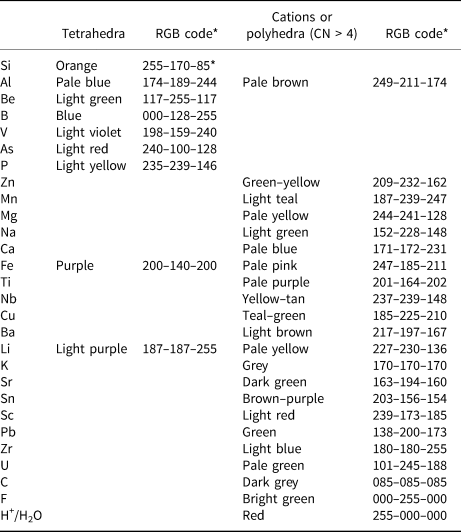
With such a wide compositional range of minerals and large number of structures, the colour scheme for the various polyhedra is somewhat complicated; we list the general colour scheme in Table 1 and will not refer to this scheme in the figure captions. In some cases, other aspects of a structure need to be emphasised by using the colours that do not correspond to Table 1; where this is done, the colour scheme will be noted in the figure caption. The structure of a given mineral is typically shown in two or three different orientations. The relation between these orientations is shown by outlining the part of the structure in (a) that is shown in (b) or (c) using dashed black lines and the labels (b’) and (c’), respectively. This labelling method is not described in the figure captions.
Colour scheme for polyhedra and cations.

* Colours are RGB codes from ATOMS © (from Shape Software); where colours differ from listed codes refer to the figure caption
Mineral names are written in bold font to aid comparison of different minerals throughout the text. In the tables, we have attempted to write each mineral as the principal end-member formula (Hawthorne, Reference Hawthorne2002), as this simplifies the connections between mineral composition and bond topology. In the tables, the silicate unit (i.e. the silicate part of the structure) is written in bold font and in square brackets, except where there is some question as to the formula of the silicate unit (e.g. where there is significant disorder of the constituents of that unit). Bond-valences were calculated with the parameters of Gagné and Hawthorne (Reference Gagné and Hawthorne2015). We have also gathered together all the information of Tables 3–9 in an Excel file, so that the information given here can be conveniently retrieved, searched and sorted with a macro that we have written. This file has been deposited as Supplementary material with the Principal Editors of Mineralogical Magazine (details below).
Silicate
Where we refer to a silicate unit (e.g. silicate chain, ribbon and/or tube), let it be understood that the unit must contain Si4+ but may also contain other tetrahedrally coordinated cations: e.g. T = P5+, V5+, As5+, Al3+, Fe3+, B3+, Be2+, Zn2+ and Mg2+. For simplicity of expression, we refer to such compositions as silicates, whether or not the dominant tetrahedrally coordinated cation is Si4+, as we require them to contain Si4+ as an essential constituent. Chains and ribbons that contain no Si4+-tetrahedra will be discussed if such minerals provide insight into the relation between composition and structure; examples include the aluminate minerals addibischoffite and warkite. Synthetic compounds will be discussed if they contain chains, ribbons or tubes of Si4+-tetrahedra that are topologically unique or intermediate between other chains in the hierarchy.
We will refer to a tetrahedron or any other higher coordination polyhedron by its central cation if the anions coordinating that cation are solely O2− or if the identity of such anions is unclear. It follows that the expression Si4+-tetrahedron (tetrahedrally coordinated Si4+) or Na+-octahedron (octahedrally coordinated Na+) represents a (Si4+O4)4−-tetrahedron or a (Na+O6)11−-octahedron, respectively and a ‘T-tetrahedron’ represents a (TO4)n− tetrahedron, where T is one or more unspecified tetrahedrally coordinated cation. If the anions that coordinate any given cation are anything other than O2− (i.e. (OH)−, (H2O), F−), the expanded notation for that cation-polyhedron will be given, e.g. (Na+O4(OH)2)9−-octahedron or (SiO3(OH))3−-tetrahedron. Where coordination number is not expressed in this notation, it will be appended to the central cation of the respective polyhedron or ion (e.g. [7]Na+-polyhedron or [8]Ba+ ion).
We define chains, ribbons, and tubes of T-tetrahedra as follows:
-
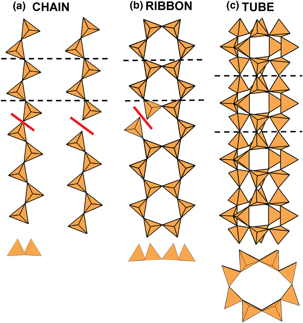
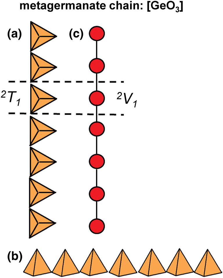
Chain: a silicate unit of (TO4)n− tetrahedra that link infinitely in a single direction and that can be broken by eliminating a single linkage between adjacent (TO4)n− tetrahedra (Fig. 1a).
-
Ribbon: a silicate unit of (TO4)n− tetrahedra that link infinitely in a single direction and that cannot be broken by eliminating a single linkage between adjacent (TO4)n− tetrahedra (Fig. 1b).
-
Tube: a silicate unit of (TO4)n− tetrahedra that link infinitely in a single direction, and also link orthogonal to the direction of polymerisation to form a hollow cylinder. A silicate tube cannot be broken by eliminating a single linkage between adjacent (TO4)n− tetrahedra (Fig. 1c).
For simplicity, we will refer to all chain-, ribbon- and tube-silicate minerals and structures as chain silicates and chains, respectively. A layer is a single planar or semi-planar array of ions. A sheet is a single planar or semi-planar array of linked polyhedra.
Definitions of a silicate chain, ribbon and tube: (a) a chain: if the linkage between two tetrahedra is broken, the one-dimensional polymerisation is lost; (b) a ribbon: if the linkage between two tetrahedra is broken, the one-dimensional polymerisation is not lost; (c) a tube: if the linkage between two tetrahedra is broken, the one-dimensional polymerisation is not lost, and also the tetrahedra fold round on themselves perpendicular to the direction of polymerisation to form a hollow cylinder. Dashed black lines show the geometrical repeat unit of the chain, ribbon and tube.
Low-acidity [4]T cations: Alkali metals
There is some ambiguity about the [4]-coordinated ions Li+, Na+, K+, Rb+ and Tl+. These ions all have Lewis acidities (Gagné and Hawthorne, Reference Gagné and Hawthorne2017) lower than the cut-off of 0.30 vu used by Hawthorne and Schindler (Reference Hawthorne and Schindler2008) to exclude ions from the structural unit, and using this criterion, we would exclude such ions from the chain. Conversely, from a topological perspective, one might wish to include all tetrahedrally coordinated cations. In some cases, the same structure types may incorporate different cations with a range of valence states at a tetrahedrally coordinated site; for example, in the milarite structure (Gagné and Hawthorne, Reference Gagné and Hawthorne2016), the T2 site in the framework may be occupied by Li+ (e.g. berezanskite, Hawthorne et al., Reference Hawthorne, Sokolova, Pautov, Agakhanov and Karpenko2016; sogdianite; Sokolova et al., Reference Sokolova, Hawthorne and Pautov2000), and various divalent (Be2+, Mg2+, Fe2+ and Zn2+) and trivalent (B3+, Al3+ or Fe3+) cations. It seems undesirable to separate isostructural minerals on the basis of Lewis acidity of the T cation and we include such minerals in the same group here.
Graphical (topological) and geometrical chain representations
Two- and three-dimensional graphs (or nets) are commonly used to describe and analyse the structures of sheet-silicate and framework-silicate minerals (e.g. Wells, Reference Wells1962, Reference Wells1977; Smith, Reference Smith1977, Reference Smith1978, Reference Smith1988; Hawthorne, Reference Hawthorne2015a; Hawthorne and Smith, Reference Hawthorne and Smith1986a,Reference Hawthorne and Smithb, Reference Hawthorne and Smith1988; Hawthorne et al., Reference Hawthorne, Uvarova and Sokolova2019; Krivovichev, Reference Krivovichev2008, Reference Krivovichev2009) and some tubular chain silicates (Rozhdestvenskaya and Krivovichev, Reference Rozhdestvenskaya and Krivovichev2011). However, there is no complete description of silicate chains, ribbons and tubes as one-dimensional graphs. We will take this approach here as it: (1) leads to compact representations of the connectivity of silicate chains, ribbons and tubes; (2) simplifies comparison of different structures; and (3) facilitates theoretical analysis of all possible chain, ribbon and tube arrangements of polymerised tetrahedra. Here, chain-, ribbon- and tube-silicate structures are commonly shown in three representations: (1) polyhedron representations where (TO4)n− groups are shown as tetrahedra and the original chain geometry is preserved (Fig. 2a); (2) ball-and-stick representations in which tetrahedra are represented by points and links between tetrahedra are represented by lines, and the original chain geometry is preserved (Fig. 2b); and (3) representations in which the chain is reduced to a graph in which tetrahedra are represented by vertices and linkages between tetrahedra are represented by edges, and the original chain geometry is not preserved (Fig. 2c). Throughout this paper, the geometry, topology and connectivity of each chain, ribbon and tube will be described by reducing each chain to a single repeat unit that can be linked infinitely by translation in a single direction to produce the chain.
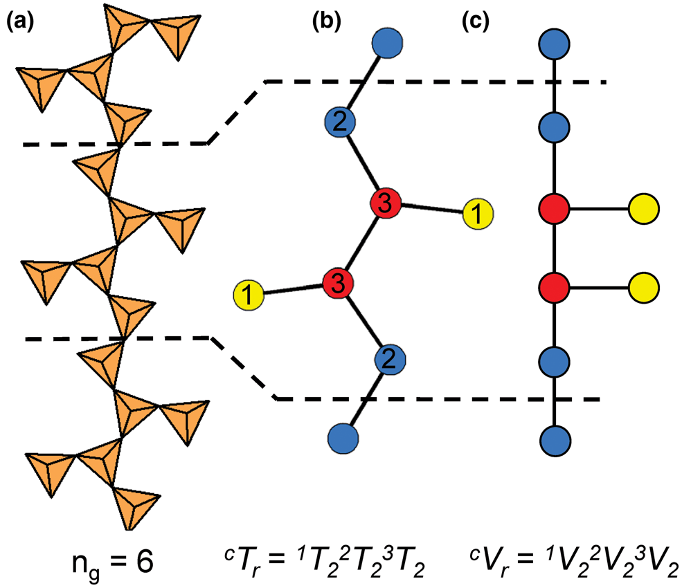
(a) Tetrahedral, (b) ball-and-stick and (c) graphical representations of the chain in sapphirine-supergroup minerals viewed orthogonal to the c-axis. Each tetrahedron in (a) is represented by a point (ball) in (b) and a vertex in (c), and all linkages between tetrahedra in (a) are represented by lines (sticks) in (b) and edges in (c) that connect each ball or vertex. Red, blue and yellow points (circles) represent 3−, 2− and 1−connected vertices. Dashed black lines show the geometrical repeat unit in (a) and (b) and the topological repeat unit in (c).
The geometrical repeat unit and the cTr expression
In the tetrahedron and ball-and-stick representations, we assign a geometrical repeat unit in which the geometry of the chain (lengths and angles of linkages between tetrahedra) is preserved. The geometrical repeat unit contains the minimum number of tetrahedra (ng) required to generate the chain through translation operations. It is necessary to specify the numbers of 1-, 2-, 3- and 4-connected tetrahedra that comprise ng to describe the geometrical repeat unit of a chain. To do this, we denote a tetrahedron by T, its connectivity by the superscript c (c = 1–4) and the number of such tetrahedra in the geometrical repeat unit by the subscript r. The expression cTr = 1Tr2Tr3Tr4Tr represents the possible connectivities of tetrahedra in the repeat unit, and the number of terms with r ≠ 0 in the cTr expression is defined as its rank. The majority of chains contain only 2- and 3-connected vertices (i.e. cTr has a rank of 2 as r = 0 for 1Tr and4Tr), but some chains also contain 1- and/or 4-connected vertices. As an example, consider the tetrahedron (Fig. 2a) and ball-and-stick (Fig. 2b) representations of the [Si6O18]12− chain in sapphirine-supergroup minerals. The ball-and-stick representation shows three types of vertices: 3-connected (red circles), 2-connected (blue circles) and 1-connected (yellow circles) (Fig. 2b). The repeat unit contains two of each of these types of vertex (ng = 6), and the cT r expression for the aenigmatite-type chain is written as cTr = 1T22T23T24T0 = 1T22T23T2 (rank = 3).
We can generate all possible cT r expressions for chains with tetrahedron connectivities, c, of 1, 2, 3 and 4 where r = 1 to ∞ by sequentially increasing the values of c and r. There are various ways in which this may be done. However, the most useful way is to order these in terms of increasing rank of cTr (i.e. the number of individual cTr vaues). For a given rank, we sequentially increase the value of c for r = 1 to ∞; Table 2 shows the cTr expressions produced in this way. For a rank of 1, where c = 1, a chain is not possible: 1T1 corresponds to single tetrahedron; 1T2 corresponds to a [T2O7] dimer, and no further linkages are possible without changing the value of c (Table 2). Thus, 2T1 is the simplest possible chain arrangement, followed by 2T2, 2T3, 2T4 etc. For higher ranks, we order cTr first in terms of c and then in terms of r, hence for a rank of 2: 2Tr3Tr, we have 2T13Tr, 2T23Tr, 2T33Tr……. etc. Thus we have a rationale for both generating all theoretical chains and ordering observed chains into a preliminary hierarchy.
Hierarchical ordering of cTr values where r = 1–∞ and c = 1–4.

The topological repeat unit
Graphical representations of chains have a topological repeat unit in which only the topological properties are preserved. The topological repeat unit contains the minimum number of vertices (nt) required to generate the chain through infinite linkage in a single direction. By analogy with the geometrical repeat unit, we may describe the topological repeat unit using the expression cVr = 1Vr2Vr3Vr4Vr where cVr denotes the connectivity of vertices (V) rather than tetrahedra (T).
In many chains, tetrahedra are topologically identical but geometrically distinct. This often results in chains with geometrical and topological repeat units that contain different numbers of tetrahedra and vertices. Figures 3a,b show the tetrahedron and ball-and-stick representations of the chain in astrophyllite-supergroup minerals, where cTr = 3T21T2 is the connectivity of the tetrahedra in the geometrical repeat unit. Figure 3c shows the graphical representation of the same chain with a topological repeat unit that contains two vertices rather than four as shown in the ball-and-stick representation (Fig. 3b); this is because the direction of branching of 1-connected vertices (or tetrahedra) does not affect the topology of the linkage. It follows that we may describe the topological repeat unit in astrophyllite-supergroup minerals as cVr = 3V11V1. Hence the cVr expression for a topological repeat unit may be derived by multiplying the values of r in the respective cTr expression by nt/ng. For some chains, ribbons and tubes, a graphical representation will not be given if such a representation further obscures the connectivity of vertices and/or if cTr = cVr (ng = nt).
(a) Tetrahedral, (b) ball-and-stick and (c) graphical representations of the chain in astrophyllite-supergroup minerals where cT r ≠ cV r.

Group and class
In Mineralogy, a group is defined as two or more minerals with the same or similar structure and chemical composition, a group may belong to a single supergroup and/or have multiple subgroups, and supergroups may belong to a single class or subclass (Mills et al., Reference Mills, Hatert, Nickel and Ferraris2009). Here, we also use the words group and class in their general sense: [1] group indicates a collection of minerals with same cTr and/or cVr expression; [2] class organises minerals with cTr expressions in which the tetrahedron connectivity is the same (c) but not necessarily the number of tetrahedra with that connectivity (r). For example, the hierarchy class 3Tr contains the groups 3T4, 3T6, 3T8, 3T12, 3T16, 3T17, 3T32 and 3T56.
Structure hierarchy
Structure hierarchies for most mineral classes and subclasses are based on cation-coordination polyhedra with the highest bond-valences, examples of which include (S6+O4)2−, (P5+O4)3− and (As5+O4)3− tetrahedra (Hawthorne, Reference Hawthorne2014). With respect to chain silicates, the relatively high bond-valence associated with the (TO4)n−-tetrahedron results in a strongly bonded, high-enthalpy tetrahedron. In chain silicates, such tetrahedra polymerise infinitely in a single direction to form the chain, ribbon or tube of the structure. Excess charge is balanced by lower-valence cations interstitial to the silicate unit. Most structure hierarchies follow the idea of Binary Structural Representation (Hawthorne, Reference Hawthorne1983a, Reference Hawthorne1985, Reference Hawthorne1986, Reference Hawthorne1990, Reference Hawthorne1992; Hawthorne and Schindler, Reference Hawthorne and Schindler2008) in which structures are partitioned into a strongly bonded structural unit and a weakly bonded interstitial complex. The Principle of Correspondence of Lewis-acidity–Lewis-basicity (Hawthorne, Reference Hawthorne2012a,Reference Hawthorneb) examines the controls on chemical composition and on the structural arrangement of both the structural unit and the interstitial complex (e.g. Schindler and Hawthorne, Reference Schindler and Hawthorne2001a,Reference Schindler and Hawthorneb,Reference Schindler and Hawthornec, Reference Schindler and Hawthorne2004, Reference Schindler and Hawthorne2008; Schindler et al., Reference Schindler, Hawthorne and Baur2000, Reference Schindler, Huminicki and Hawthorne2006). The development of a structure hierarchy for silicate minerals needs to focus solely on the polymerisation of the silicate unit (sensu late) at this stage as the polymerisation of tetrahedra is orders of magnitude more complicated than polymerisation of any other oxysalt polyhedron. Thus here we focus on silicate polymerisation and do not consider bonds to other higher-coordination cations that would normally be considered as part of a structural unit in other classes of oxysalt minerals. Hence here we divide the structure into a silicate unit and an interstitial structure (not complex) that contains the rest of the structure. The initial ordering of chains, ribbons and tubes follows the hierarchy of cTr expressions listed in Table 2.
We plan to examine the interaction of the silicate unit with the interstitial cations and anions in our future work on chain-silicate minerals, and here we also describe the coordination of the interstitial cations and (H2O), unless the details are obscured by positional disorder. We differentiate between Transformer (H2O)t, Non-Transformer (H2O)n, Inverse-Transformer (H2O)i and solely hydrogen-bonded (H2O)z groups where possible (Hawthorne, Reference Hawthorne1992; Hawthorne and Schindler, Reference Hawthorne and Schindler2008; Hawthorne and Sokolova, Reference Hawthorne and Sokolova2012). Literature references to specific minerals are made in the tables (not the text) except where dealing with more general topics.
2Tr class
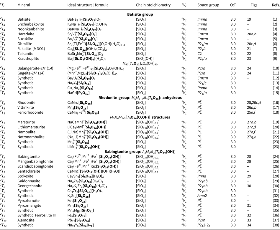
The number of 2-connected tetrahedra in the repeat unit of any 2Tr chain is equal to the periodicity of that chain and is therefore the same in chain silicates with identical chain geometry. Here, the r value is used to subdivide all chain silicates with 2Tr chains into ten groups where r = 1, 2, 3, 4, 5, 6, 7, 9, 12 and 24 (Tables 3–5). Belov (Reference Belov1961) showed how the size of the higher-coordinated cations can affect the geometry and periodicity of the [TO3]n− chains, and this is apparent in many of the figures illustrating these chains. We will examine the interaction between the silicate unit and the rest of the structure in detail in a later paper. All 2Tr chains are topologically identical and hence have a topological repeat unit that contains a single 2-connected vertex: 2V1.
Minerals with 2T2 chains.

References: (1) Krivovichev et al. (Reference Krivovichev, Filatov and Semenova1998); (2) Warren and Bragg (Reference Warren and Bragg1928); (3) Merlino et al. (Reference Merlino, Pasero and Khomyakov1990), Yakovenchuk et al. (Reference Yakovenchuk, Krivovichev, Pakhomovsky, Selivanova, Ivanyuk and Krivovichev2012); (4) Yakovenchuk et al. (Reference Yakovenchuk, Ivanyuk, Pakhomovsky, Selivanova, Men'shikov, Korchak, Krivovichev, Spiridonova and Zalkind2010); (5) Yakovenchuk et al. (Reference Yakovenchuk, Ivanyuk, Krivovichev, Pakhomovsky, Selivanova, Korchak, Men'shikov, Drogobuzhskaya and Zalkind2011); (6) Merlino et al. (Reference Merlino, Pasero and Ferro2000b); (7) Gault et al. (Reference Gault, Ercit, Grice and Velthuizen2004); (8) Naumova et al. (Reference Naumova, Pobedimskaya and Belov1974), Ghose et al. (Reference Ghose, Sen Gupta, Boggs and Schlemper1989); (9) Zhizhong et al. (Reference Zhizhong, Zhesheng and Shaoxu1987); (10) MacGillavry et al. (Reference MacGillavry, Korst, Moore and Van Der Plas1956), Viswanathan and Seidel (Reference Viswanathan and Seidel1979); (11) Viswanathan (Reference Viswanathan1981), Fuchs et al. (Reference Fuchs, Mellini and Memmi2001); (12) Basso et al. (Reference Basso, Cabella, Lucchetti, Martinelli and Palenzona2005); (13) Tait et al. (Reference Tait, Hawthorne, Grice, Jambor and Pinch2004); (14) Nyfeler et al. (Reference Nyfeler, Armbruster, Dixon and Bermanec1995); (15) Hang et al. (Reference Hang, Simonov and Belov1969), Sundberg et al. (Reference Sundberg, Lehtinen and Kivekäs1987); (16) Evans and Mrose (Reference Evans and Mrose1977), Newberg (Reference Newberg1964), Evans and Mrose (Reference Evans and Mrose1966); (17) Callegari et al. (Reference Callegari, Boiocchi, Bellatreccia, Caprilli, Medenbach and Cavallo2011); (18) Zubkova et al. (Reference Zubkova, Pekov, Pushcharovskii and Kazantsev2009b), Pekov et al. (Reference Pekov, Zubkova, Chukanov, Zadov, Grishin and Pushcharovsky2010b); (19) Rius et al. (Reference Rius, Crespi, Roig and Melgarejo2009), Rius et al. (Reference Rius, Elkaim and Torrelles2004); (20) Grosse and Tillmanns (Reference Grosse and Tillmanns1974); (21) George et al. (Reference George, Richet and Stebbins1998); (22) Jansen et al. (Reference Jansen, Heidebrecht, Matthes and Eysel1991); (23) McDonald and Cruickshank (Reference McDonald and Cruickshank1967); (24) Simonov et al. (Reference Simonov, Belokoneva and Belov1980); (25) Gunawardane et al. (Reference Gunawardane, Cradwick and Dent Glasser1973).
* Indicates the cTr expression of an additional structural unit including a chain, ribbon, tube, cluster or sheet of [TO4]n− tetrahedra in the respective mineral.
Minerals with 2T3 chains.

References: (1) Hesse (Reference Hesse1984), Henmi et al. (Reference Henmi, Kawahara, Henmi, Kusachi and Takéuchi1983), Prewitt and Buerger (Reference Prewitt and Buerger1963), Mamedov and Belov (Reference Mamedov and Belov1956); (2) Shchipalkina et al. (Reference Shchipalkina, Pekov, Ksenofontov, Chukanov, Belakovskiy and Koshlyakova2018); (3) Peacor and Buerger (Reference Peacor and Buerger1962a), Peacor and Prewitt (Reference Peacor and Prewitt1963), Aksenov et al. (Reference Aksenov, Shipalkina, Rastsvetaeva, Rusakov, Pekov, Chukanov and Yapaskurt2015), Shchipalkina et al. (Reference Shchipalkina, Chukanov, Rusakov, Pekov, Koshlyakova and Scholz2019a); (4) Yamanaka et al. (Reference Yamanaka, Sadanaga and Takeuchi1977), Rapoport and Burnham (Reference Rapoport and Burnham1973); (5) Chukanov et al. (Reference Chukanov, Aksenov, Rastsvetaeva, Van, Belakovskiy, Pekov, Gurzhiy, Schüller and Ternes2015a); (6) Takéuchi and Kudoh (Reference Takéuchi and Kudoh1977), Prewitt (Reference Prewitt1967), Prewitt and Buerger (Reference Prewitt and Buerger1963), Buerger (Reference Buerger1956); (7) Ohashi and Finger (Reference Ohashi and Finger1978), Schaller (Reference Schaller1955); (8) Imaoka et al. (Reference Imaoka, Nagashima, Kano, Kimura, Chang and Fukuda2017); (9) Nagase et al. (Reference Nagase, Hori, Kitamine, Nagashima, Abduriyim and Kuribayashi2012); (10) Williams and Weller (Reference Williams and Weller2014), Rozhdestvenskaya and Vasilieva (Reference Rozhdestvenskaya and Vasilieva2014); (11) Mitchell et al. (Reference Mitchell, Welch, Kampf, Chakhmouradian and Spratt2015); (12) Hybler et al. (Reference Hybler, Petříček, Jurek, Skála and Císařová1997), Pautov et al. (Reference Pautov, Belakovsku, Skála, Sokolova, Ignatenko and Mokhov1992); (13) Mellini and Merlino (Reference Mellini and Merlino1982), Mellini et al. (Reference Mellini, Merlino, Orlandi and Rinaldi1982); (14) Grigorieva et al. (Reference Grigor'eva, Zubkova, Pekov and Pushcharovsky2009), Chao et al. (Reference Chao, Watkinson and Chen1974); (15) Boggs (Reference Boggs1988), Pushcharovsky et al. (Reference Pushcharovsky, Pekov, Pasero, Gobechiya, Merlino and Zubkova2002); (16) Voloshin et al. (Reference Voloshin, Pakhomovskiy, Men'shikov, Sokolova and Yegorov-Tismenko1990); Sokolova et al. (Reference Sokolova, Arakcheeva and Voloshin1991); (17) Rastsvetaeva and Khomyakov (Reference Rastsvetaeva and Khomyakov1992), Khomyakov et al. (Reference Khomyakov, Nechelustov and Rastsvetaeva1993); (18) Khomyakov et al. (Reference Khomyakov, Nechelyustov and Rastsetaeva1996), Rastsvetaeva and Khomyakov (Reference Rastsvetaeva and Khomyakov1996); (19) Zubkova et al. (Reference Zubkova, Kolitsch, Pekov, Turchkova, Vigasina, Pushcharovsky and Tillmans2009a), Pekov et al. (Reference Pekov, Grigorieva, Zubkova, Turchkova and Pushcharovsky2010a); (20) Pekov et al. (Reference Pekov, Zubkova, Yapaskurt, Belakovskiy, Lykova, Britvin, Turchkova and Pushcharovsky2017); (21) Ilyushin et al. (Reference Ilyushin, Khomyakov, Shumyatskaya, Voronkov, Nevskii, Ilyukhin and Belov1981), Sebastián et al. (Reference Sebastián, Dĺaz, Téllez, Coronas and Santamarĺa2008); (22) Khomyakov et al. (Reference Khomyakov, Voronkov, Kobyashev and Polezhaeva1983a); (23) Ilyukhin et al. (Reference Ilyukhin, Pudovkina, Voronkov, Khomyakov and Pyatenko1981), Khomyakov et al. (Reference Khomyakov, Voronkov, Polezhaeva and Smolyaninova1983c); (24) Fewox et al. (Reference Fewox, Clearfield and Celestian2011); (25) Garbev (Reference Garbev2004), Gard and Taylor (Reference Gard and Taylor1958), Gard and Taylor (Reference Gard and Taylor1960); (26) Dai and Post (Reference Dai and Post1995), Xu and Boggs (Reference Xu and Boggs1996); (27) Bonaccorsi et al. (Reference Bonaccorsi, Merlino and Taylor2004), Gard et al. (Reference Gard, Taylor, Cliff and Lorimer1977), Carpenter et al. (Reference Carpenter, Chalmers, Gard, Speakman and Taylor1966); (28) Bonaccorsi et al. (Reference Bonaccorsi, Merlino and Taylor2004); (29) Bonaccorsi et al. (Reference Bonaccorsi, Merlino and Kampf2005), McConnell (Reference McConnell1954); (30) Taylor (Reference Taylor1953), Biagioni et al. (Reference Biagioni, Merlino and Bonaccorsi2015); (31) Kampf et al. (Reference Kampf, Mills, Merlino, Pasero, McDonald, Wray and Hindman2012).
Minerals with 2T4–7, 2T9, 2T12 and 2T24 chains.
References: (1) Nikitin and Belov (Reference Nikitin and Belov1962), Schmahl and Tillmanns (Reference Schmahl and Tillmanns1987), Rastsvetaeva et al. (Reference Rastsvetaeva, Pushcharovskii, Konev and Evsunin1997a), Zolotarev et al. (Reference Zolotarev, Zhitova, Gabdrakhmanova, Krzhizhanovskaya, Zolotarev and Krivovichev2017); (2) Uvarova et al. (Reference Uvarova, Sokolova, Hawthorne, Liferovich and Mitchell2003), Krivovichev et al. (Reference Krivovichev, Yakovenchuk and Pakhomovsky2004b); (3) Prider (Reference Prider1965), Rastsvetaeva et al. (Reference Rastsvetaeva, Pushcharovskii, Konev and Evsunin1997a), Uvarova et al. (Reference Uvarova, Sokolova, Hawthorne, Liferovich, Mitchell, Pekov and Zadov2010); (4) Berger and Range (Reference Berger and Range1996), Takéuchi and Joswig (Reference Takéuchi and Joswig1967), Watanabe et al. (Reference Watanabe, Kato, Ito, Yoshimura, Momoi and Fukuda1982), Basso et al. (Reference Basso, Lucchetti, Palenzona and Zefiro1995); (5) Matsubara et al. (Reference Matsubara, Kato and Yui1982), Ito et al. (Reference Ito, Matsubara, Yokoyama, Momma, Miyawaki, Nakai and Kato2014); (6) Mizota et al. (Reference Mizota, Komatsu and Chihara1983), Mizota et al. (Reference Mizota, Komatsu and Chihara1973), Komatsu et al. (Reference Komatsu, Chihara and Mizota1973); (7) Merlino et al. (Reference Merlino, Bonaccorsi, Grabezhev, Zadov, Pertsev and Chukanov2009), Henmi et al. (Reference Henmi, Kusachi, Kawahara and Henmi1977), Rastvetaeva et al. (Reference Rastsvetaeva, Bolotina, Zadov and Chukanov2005); (8) Armbruster et al. (Reference Armbruster, Oberhänsli and Kunz1993), Kalinin et al. (Reference Kalinin, Dauletkulov, Gorshkov and Troneva1985); (9) Coda et al. (Reference Coda, Dal Negro and Rossi1967), Alfors et al. (Reference Alfors, Stinson, Matthews and Pabst1965); (10) Bonaccorsi et al. (Reference Bonaccorsi, Ferraris and Merlino2012), Compagnoni et al. (Reference Compagnoni, Ferraris and Fiora1983), Ferraris et al. (Reference Ferraris, Mellini and Merlino1987), Belluso and Ferraris (Reference Belluso and Ferraris1991); (11) Moore (Reference Moore1969a), Dunn (Reference Dunn1979); (12) Plaisier et al. (Reference Plaisier, Ijdo, de Mello Donego and Blasse1995); (13) Toebbens et al. (Reference Toebbens, Kahlenberg and Kaindi2005); (14) Kawamura and Kawahara (Reference Kawamura and Kawahara1976); (15) Amami et al. (Reference Amami, Fend and Trabelsi-Ayedi2005); (16) Pertlik and Zahiri (Reference Pertlik and Zahiri1999), Peacor and Niizeki (Reference Peacor and Niizeki1963), Peacor et al. (Reference Peacor, Essene, Brown and Winter1978a), Pinckney and Burnham (Reference Pinckney and Burnham1988); Leverett et al. (Reference Leverett, Williams and Hibbs2008); (17) Pertlik and Zahiri (Reference Pertlik and Zahiri1999), Shchipalkina et al. (Reference Shchipalkina, Pekov, Chukanov, Biagioni and Pasero2019b); (18) Shchipalkina et al. (Reference Shchipalkina, Chukanov, Pekov, Aksenov, McCammon, Belakovskiy, Britvin, Koshlyakova, Schäfer, Scholz and Rastsvetaeva2017, Reference Shchipalkina, Chukanov, Rusakov, Pekov, Koshlyakova and Scholz2019a); (19) Nagashima et al. (Reference Nagashima, Armbruster, Kolitsch and Pettke2014a), Peacor et al. (Reference Peacor, Dunn and Sturman1978b), Kolitsch (Reference Kolitsch2008); (20) Yang et al. (Reference Yang, Downs and Yang2011), Peacor et al. (Reference Peacor, Dunn, White, Grice and Chi1990); (21) Narita et al. (Reference Narita, Koto, Morimoto and Yoshii1975), Yoshii et al. (Reference Yoshii, Aoki and Maeda1972), Mukhopadhyay et al. (Reference Mukhopadhyay, Das and Fukuoka2005), Murakami et al. (Reference Murakami, Takéuchi, Tagai and Koto1977); (22) Nagashima et al. (Reference Nagashima, Armbruster, Kolitsch and Pettke2014a), Matsubara et al. (Reference Matsubara, Kato and Tiba1985); (23) Ito (Reference Ito1972); (24) Akasaka et al. (Reference Akasaka, Kimura and Nagashima2013), Araki and Zoltai (Reference Araki and Zoltai1972), Kosoi (Reference Kosoi1975), Czank (Reference Czank1981), Armbruster, (Reference Armbruster2000), Nagashima et al. (Reference Nagashima, Mitani and Akasaka2014b); (25) Vinogradova et al. (Reference Vinogradova, Sychkova and Kabalov1966); (26) Orlandi et al. (Reference Orlandi, Pasero and Vezzalini1998); (27) Ohashi and Finger (Reference Ohashi and Finger1981), Erd and Ohashi (Reference Erd and Ohashi1984); (28) Vorma (Reference Vorma1963), Gay and Rickson (Reference Gay and Rickson1960), Yuan et al. (Reference Yuan, Guowu and Guangming2017); (29) Chao and Watkinson (Reference Chao and Watkinson1974), Chao (Reference Chao1985), Donnay and Chao (Reference Donnay and Chao1986), Larsen and Raade (Reference Larsen and Raade1991), Celestian et al. (Reference Celestian, Lively and Xu2019); (30) Ghose and Thakur (Reference Ghose and Thakur1985), Boggs and Ghose (Reference Boggs and Ghose1985); (31) Celestian et al. (Reference Celestian, Lively and Xu2019); (32) Kahlenberg et al. (Reference Kahlenberg, Kaindl and Sartory2007); (33) Burnham (Reference Burnham1971), Lindsley and Burnham (Reference Lindsley and Burnham1970), Shchipalkina et al. (Reference Shchipalkina, Aksenov, Chukanov, Pekov, Rastsvetaeva, Schäfer, Ternes and Shüller2016a); (34) Narita et al. (Reference Narita, Koto and Morimoto1977), Liebau (Reference Liebau1957), Zanazzi et al. (Reference Zanazzi, Nestola, Nazzareni and Comodi2008); (35) Finger and Hazen (Reference Finger and Hazen1978) (36) Weber (Reference Weber1983), Liebau (Reference Liebau1985); (37) Krivovichev and Burns (Reference Krivovichev and Burns2004), Boucher and Peacor (Reference Boucher and Peacor1968); (38) Maksimov et al. (Reference Maksimov, Kalinin, Merinov, Ilyukhin and Belov1980).
2T1 chains
The metagermanate chain, [GeO3] (Krivovichev et al., Reference Krivovichev, Filatov and Semenova1998, fig. 4.C1), is the only known structure with 2T1 chains (Figs 4a,b) in which each 2-connected (GeO4)4−-tetrahedron is geometrically and topologically identical (Fig. 4c). 2T1 chains are the simplest possible chain-type and constitute the first group of the 2Tr class where r = 1 (Tables 2 and 3).
(a, b) Tetrahedral representation of the 2T1 [GeO3] chain viewed orthogonal to the length of the chain; (c) a graphical representation of the chain where red points (vertices) represent Si4+-tetrahedra and black lines (edges) represent linkages between adjacent Si4+-tetrahedron. Dashed black lines show the geometrical and topological repeat unit of the chain.
2T2 chains
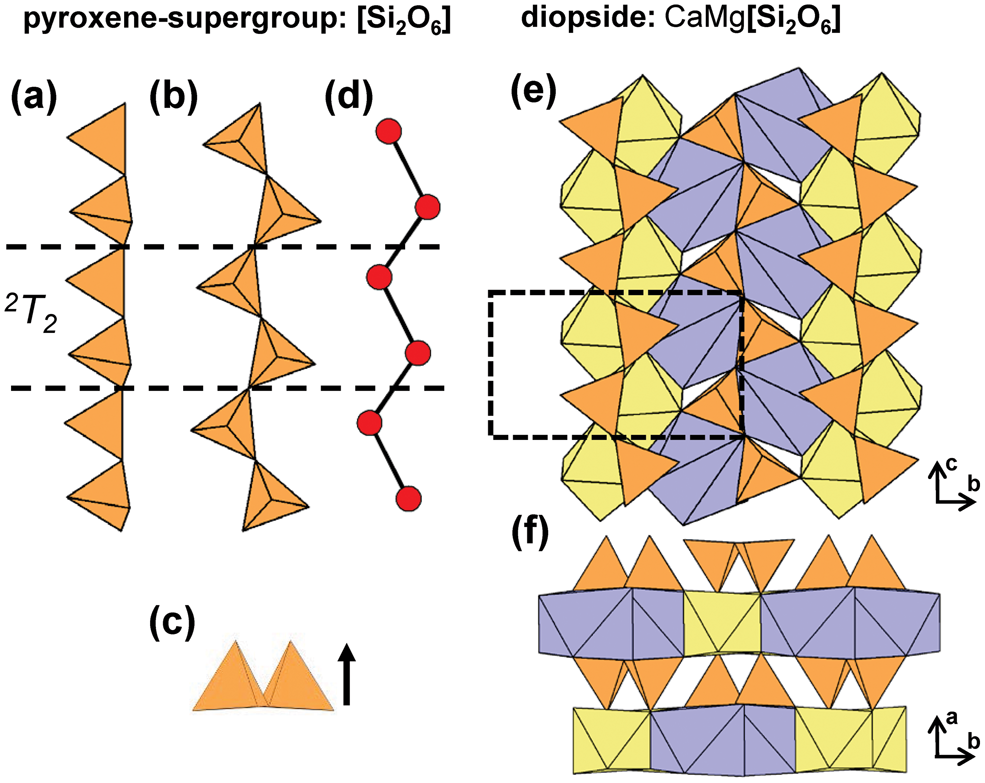
2T2 chains are extremely common and comprise one of the largest groups of minerals in the structure hierarchy (Table 3). The geometrical repeat unit of 2T2 chains contains two (TO4)n−-tetrahedra (ng = 2) that are linked to form [T2O6]n− groups that polymerise in a single direction to form the 2T2 chain in which both tetrahedra in the repeat unit may point in the same or opposing directions (Figs 5a–d). The topological repeat unit contains a single vertex that is topologically identical to all other vertices: nt = 1, as is the case for all 2Tr chains. The pyroxene supergroup are by far the most abundant minerals with this chain type; they have been described in considerable detail elsewhere (e.g. Papike et al., Reference Papike, Prewitt, Sueno and Cameron1973; Ohashi and Finger, Reference Ohashi and Finger1974; Cameron and Papike, Reference Cameron and Papike1981; Bruno et al., Reference Bruno, Carbonin and Molin1982; Rossi et al., Reference Rossi, Smith, Ungaretti and Domeneghetti1983; Tribaudino et al., Reference Tribaudino, Benna and Bruno1989; Redhammer et al., Reference Redhammer, Amthauer, Roth, Tippelt and Lottermoser2006; Nestola et al., Reference Nestola, Tribaudino, Boffa Ballaran, Liebske and Bruno2007; Abdu and Hawthorne, Reference Abdu and Hawthorne2013), and we will consider them here only briefly. Typically, 2T2 chains extend along the c-axis and link to ribbons of edge-sharing octahedra; in diopside, there are alternating layers of 2T2 chains and sheets of Mg2+-octahedra and [7]Ca2+-polyhedra (Figs 5e,f). This general stacking sequence of chains of tetrahedra and sheets of octahedra (or higher-coordination polyhedra) is common in chain silicates that contain 2T2 chains.
(a, b, c) Tetrahedral representations of the 2T2 chain in pyroxenes where both tetrahedra in the geometrical repeat unit point in the same direction and (d) a ball-and-stick representation of the chain. The structure of diopside projected (e) onto (100) and (f) along the c-axis. Dashed black lines show the geometrical repeat unit of the chain.
Lintisite-group minerals include lintisite, punkaruaivite, eliseevite, kukisvumite and manganokukisvumite (Table 3) all of which contain 2T2 chains that occur in two distinct layers. Lintisite and punkaruaivite contain [4]Li+ and are of particular interest as Li+-tetrahedra form chains of edge-sharing tetrahedra, and we will describe the structure here. Other minerals that contain silicate ribbons in addition to 2T2 pyroxene-like chains, such as vinogradovite and paravinogradovite (see below), will be discussed in the cTr section that corresponds to the ribbon rather than the 2T2 chain. For all known chain-, ribbon- and tube-silicate minerals, tetrahedra link via corners through a common bridging anion. Such anions can link to a maximum of two Si4+-tetrahedra, allowing a maximum Si4+-connectivity of four. For a given (SiO4)4−-tetrahedron the average mean bond-valence is 1.0 vu and therefore the valence sum rule is satisfied at the O2− bridging anion (Si–O–Si). However, if substitution of Si4+ by a cation with a smaller formal valence and a lower Lewis acidity (Gagné and Hawthorne, Reference Gagné and Hawthorne2017) occurs, the mean bond-valence contribution to the bridging anion decreases which allows additional T–O linkages. This T-cation may have a connectivity of greater than four and form arrangements not observed in units composed predominately of Si4+-tetrahedra. This situation occurs in lintisite (and punkaruaivite), in which Li+-tetrahedra (mean bond-valence of 0.25 vu) have a connectivity of six and form 4T46T2 [Li2Si4O12]6− ([Li2Si4O10(OH)2]4− in punkaruaivite) ribbons, the only example of this arrangement in chain-silicate minerals; the calculated bond-valence sum for [4]Li+ (X1 cation) in lintisite is 0.92 vu.
In lintisite, there are two distinct ways in which 2T2 chains link to the rest of the structure (Fig. 6a): [1] 2T2 chains link two adjacent sheets of Ti4+-octahedra and [8]Na+-polyhedra (Na1) along the a-axis (Figs 6b); and [2] 2T2 chains link sheets of Ti4+-octahedra and [8]Na+-polyhedra (Na1) to chains of edge-sharing (LiO4)7−-tetrahedra (X1) (Figs 6c). This linkage of chains of (SiO4)4−- and (LiO4)7−-tetrahedra (X1) form 4T46T2 [Li2Si4O12]6− ribbons (Figs 6d,e) that extend along the c-axis. In lintisite, channels extend along the c-axis and are occupied by Na+ that form (NaO2(H2O)4)3−-octahedra (Na2 and W1) (Fig. 6a). In punkaruaivite, 2T2 chains and 4T46T2 [Li2Si4O10(OH)2]4− ribbons link to ribbons of edge-sharing (TiO4(OH)2)6−-octahedra instead of sheets as the Na1 site is vacant. Channels are occupied solely by (H2O) groups (W1) rather than Na2 cations as in lintisite, and the bond-valence sum at the X1-cation is 1.02 vu. Eliseevite contains only 2T2 chains and no 4T46T2 ribbon as the X1 cation forms (Li(H2O)4(OH)2)−-octahedra rather than Li+-tetrahedra. Here edge-sharing ribbons of (Li(H2O)4(OH)2)−-octahedra are linked along the a-axis to sheets of Ti4+-octahedra and [8]Na+-polyhedra via 2T2 chains. Although the bond-valence sums at the X1-cation in lintisite and punkaruaivite suggest Li+ is [4]-coordinated in this structure type, the bond-valence sums at the X1-cation in eliseevite for [4]- and [6]-coordinated Li+ are 0.75 and 0.90 vu, respectively. In kukisvumite and manganokukisvumite, Zn2+ and Mn2+ occupy the X1 site, respectively, and have both been described as tetrahedrally coordinated cations. The incident bond-valence sum at the X1-cation for Zn2+ in kukisvumite is 1.16 vu, but there are no other anions close to Zn, and Zn must be tetrahedrally coordinated. This apparent bond-valence deficiency at the X1-cation is presumably the result of the half-occupancy of the site by Zn2+ with the real Zn2+–O distances much shorter and the □–O distances much longer than the observed distances.
The structure of lintisite projected (a) along the c-axis, (b, c) onto (100), and the [Li2Si4O12]6− ribbon of [SiO4]4− and [LiO4]7− tetrahedra projected (d) onto (100) and (e) along the c-axis. Fine dashed black lines outline the unit cell which is halved along the a-axis in (a). The H atoms associated (H2O) groups have been omitted for clarity.

Although most chain silicates with 2T2 chains contain alternating layers of chains of tetrahedra and sheets of octahedra (or higher-coordination polyhedra), there are different sequences of layer stacking that involve such chains. The carpholite-group minerals (Basso and Carbone, Reference Basso and Carbone2010) include carpholite, balipholite, ferrocarpholite, magnesiocarpholite, vanadiocarpholite and potassiccarpholite with the general formula A 2BM 2Al4[Si4O12]V 4W 4 (Tait et al., Reference Tait, Hawthorne, Grice, Jambor and Pinch2004) (Table 3). In all group members, the A site is dominated by vacancy with minor Na+ and the B site is also vacant in all members except balipholite and potassiccarpholite where it is occupied by Ba2+ and K+, respectively. In carpholite, both M-octahedra are occupied by Mn2+ and share edges with Al3+-octahedra, forming ribbons that extend along [001]. These ribbons are linked to each other along [100] by chains of Al3+-octahedra, forming channels that are occupied by 2T2 [Si2O6]4− chains (Figs 7a,b). In magnesiocarpholite and ferrocarpholite, Mg2+ and Fe2+ substitute for Mn2+ at one or both of the M sites. In balipholite and potassiccarpholite, Mg2+/Li+ and Mn2+/Li+ occupy the M sites, respectively and in vanadiocarpholite V3+ substitutes for Al3+. In all carpholite-group minerals, the V and W sites are occupied by (OH)− groups except for potassiccarpholite where F− occupies the W site.
The structure of carpholite projected (a) onto (010) and (b) along the c-axis. The structure of nchwaningite projected (c) onto (100) and (d) along the c-axis. Fine dashed black lines outline the unit cell and H atoms associated with (OH)− and (H2O) groups have been omitted for clarity.

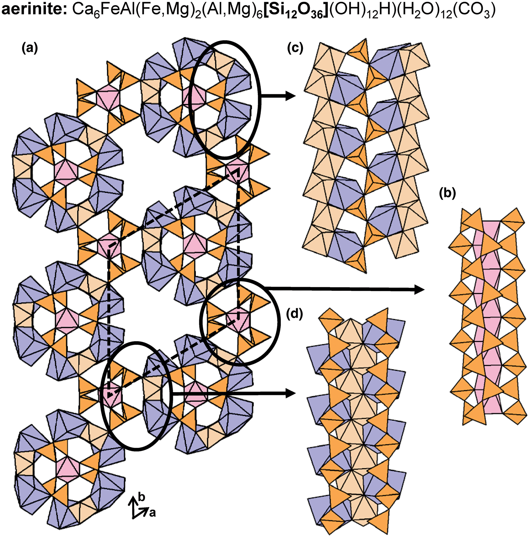
The 2T 2 chains in nchwaningite link to sheets of (MnO2(OH)3(H2O))5−-octahedra along the a-axis and the b-axis (Fig. 7c). Each Si4+–Mn2+ layer, shown in Fig. 7d, is linked to an identical layer along the b-axis via hydrogen bonding associated with (H2O) and (OH)− groups that occupy interlayer space and coordinate both Si4+ and Mn2+ ions. In lorenzenite, layers of 2T2 chains link to a double-layer sheet of Ti4+-octahedra and  $^{[7]}\hbox{Na}^+$-polyhedra rather than a single-layer sheet (Figs 8a,b). In shattuckite, 2T2 chains link to continuous, modulated single-layer sheets of (CuO4(OH)2)8−-octahedra (Cu1 and Cu2) (Fig. 8c) and chains of Cu2+-octahedra (Cu3) (Fig. 8d) that occur in layers parallel to the modulated sheets (001) (Fig. 8e). In yegorovite, both tetrahedra in the repeat unit are acid silicate (silanol) groups; (SiO3(OH))3− and point in oblique directions with respect to each another (Figs 9a–d), a notable geometric difference from the more common 2T2 minerals. Here, 2T2 chains link to modulated single-layer sheets of (NaO(H2O)3(OH)2)3−- (Na1 and Na3) and (NaO(H2O)4(OH))2−-octahedra (Na2 and Na4) that are parallel to (100) (Figs 9e,f). In aerinite, there are three distinct modes of linkage between 2T2 chains and the rest of the structure. All 2T2 chains link to chains of Fe3+-octahedra that extend along and inside and outside of tubes of Al3+-octahedra and [7]Ca2+-polyhedra and link such tubes to each other (Fig. 10a). Each chain of Fe3+-octahedra links to three different 2T2 chains (Fig. 10b). The way in which 2T2 chains and chains of Fe3+-octahedra link within tubes and between tubes of Al3+-octahedra and [7]]Ca2+-polyhedra is shown in Figs 10c,d, respectively. Aerinite also contains (H2O), (OH)− and (CO3)2− groups and we refer readers to Rius et al. (Reference Rius, Crespi, Roig and Melgarejo2009) for a more detailed structural description. Many synthetic compounds that contain 2T2 [Si2O6]4− chains have been also been described, examples of which are listed in Table 3.
The structure of lorenzenite projected (a) onto (100) and (b) along the c-axis. The structure of shattuckite projected (c, d) onto (010) and (e) along the c-axis. Fine dashed black lines outline the unit cell and H atoms associated with (OH)− groups have been omitted for clarity.

(a, b, c) Tetrahedral representations of the 2T 2 chain in yegorovite where both tetrahedra in the geometrical repeat unit point in oblique directions, and (d) a ball-and-stick representation of the chain. The structure of yegorovite projected (e) onto (001) and (f) along the a-axis. Fine dashed black lines outline the unit cell and H atoms associated with (OH)− and (H2O) groups have been omitted for clarity.

The structure of aerinite projected (a) along the c-axis and (b, c, d) the structural modules that contain 2T2 chains viewed orthogonal to the c-axis. Fine dashed black lines outline the unit cell and H atoms associated with (OH)− and (H2O) groups and C atoms associated with (CO3) groups have been omitted for clarity.
2T3 chains
In 2T3 chains there are three geometrically distinct tetrahedra in the geometrical repeat unit, and all minerals that contain 2T3 chains are listed in Table 4. There has been considerable work done on the effect of M-site substitutions on chain geometry, compositional limits and hydrogen bonding. In these minerals, M-site substitutions affect the periodicity, the geometrical aspects of the chain, and the stacking patterns of the structural elements. They are also affected by temperature (e.g. Ohashi and Finger, Reference Ohashi and Finger1976, Reference Ohashi and Finger1978; Liebau, Reference Liebau1980; Nagashima et al., Reference Nagashima, Imaoka, Fukuda and Pettke2018; Prewitt and Peacor, Reference Prewitt and Peacor1964) but these effects will not be discussed in detail here.
Of the minerals that contain 2T3 chains, wollastonite-group minerals are the most abundant and may be divided into two categories, anhydrous and hydrous, based on the absence or presence of (OH)− groups (Liebau, Reference Liebau1980) (Table 4). Wollastonite (A and M polytypes), dalnegorskite, bustamite, mendigite and ferrobustamite do not contain (OH)−, whereas pectolite, schizolite, murakamiite, tanohataite, serandite, berrydawsonite-(Y) and vistepite contain (OH)− groups (Table 4). The geometry of the chain in wollastonite-group minerals is shown in Figs 11a–d. In general, these chains contain three distinct tetrahedra and consist of c-shaped trimers that link along the b-axis, parallel to ribbons of octahedra and/or other higher coordination polyhedra (Fig. 11e), These ribbons occur in layers that alternate with layers of 2T3 chains (Fig. 11f). Thompson et al. (Reference Thompson, Yang and Downs2016) examined the relations between pyroxenoids and pyroxenes in detail.
(a, b, c) Tetrahedral representations of the 2T 3 chain in wollastonite-group minerals and (d) a ball-and-stick representation of the chain. The structure of wollastonite-2M viewed (e) orthogonal to the b-axis and (f) along the b-axis. Dashed black lines show the geometrical repeat unit of the chain and fine dashed black lines outline the unit cell.

The most common wollastonite polytypes are 1A and 2M, with 3A, 4A, 5A and 7A polytypes being less common, resulting from different stacking sequences (Henmi et al., Reference Henmi, Kawahara, Henmi, Kusachi and Takéuchi1983). Wollastonite contains three octahedrally coordinated sites that are fully occupied by Ca2+ (M1–M3) and form ribbons three octahedra wide (Figs 11e,f). The other anhydrous wollastonite-group minerals have the general formula M12M22M3M4[Si3O9]2 and include dalnegorskite, bustamite, ferrobustamite and mendigite (Table 4). These minerals contain four sites M1–M4 occupied by Ca2+, Mn2+ and Fe2+ where the M4 site is always occupied by Ca2+. In bustamite (Figs 12a,b) and ferrobustamite (Figs 12c,d), the M1 site is occupied by Ca2+ > Fe2+ and Ca2+ > Mn2+, respectively and the M3 site is occupied by Mn2+ in bustamite and Fe2+ in ferrobustamite. In the structures of bustamite, ferrobustamite and dalnegorskite, the M2 sites are occupied dominantly by Ca2+. In mendigite, the M1, M2 and M3 sites are dominated by Mn2+ (Figs 12e,f). Dalnegorskite represents the compositional limit of Ca2+ in the bustamite-type structure where M1, M2 and M4 are fully occupied by Ca2+ and M3 is occupied by Mn2+.
The structure of (a, b) bustamite, (c, d) ferrobustamite and (e, f) mendigite viewed (a, c, e) orthogonal to the b-axis and (b, d, f) along the b-axis. M-site labels in (a) are also applicable to (c) and (e). Fine dashed black lines outline the unit cell.

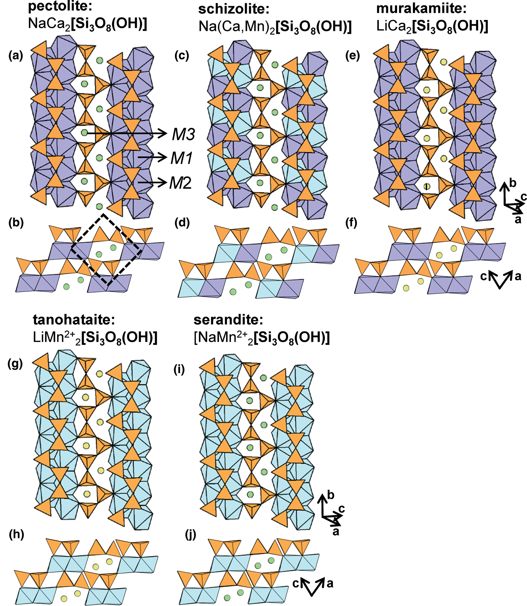
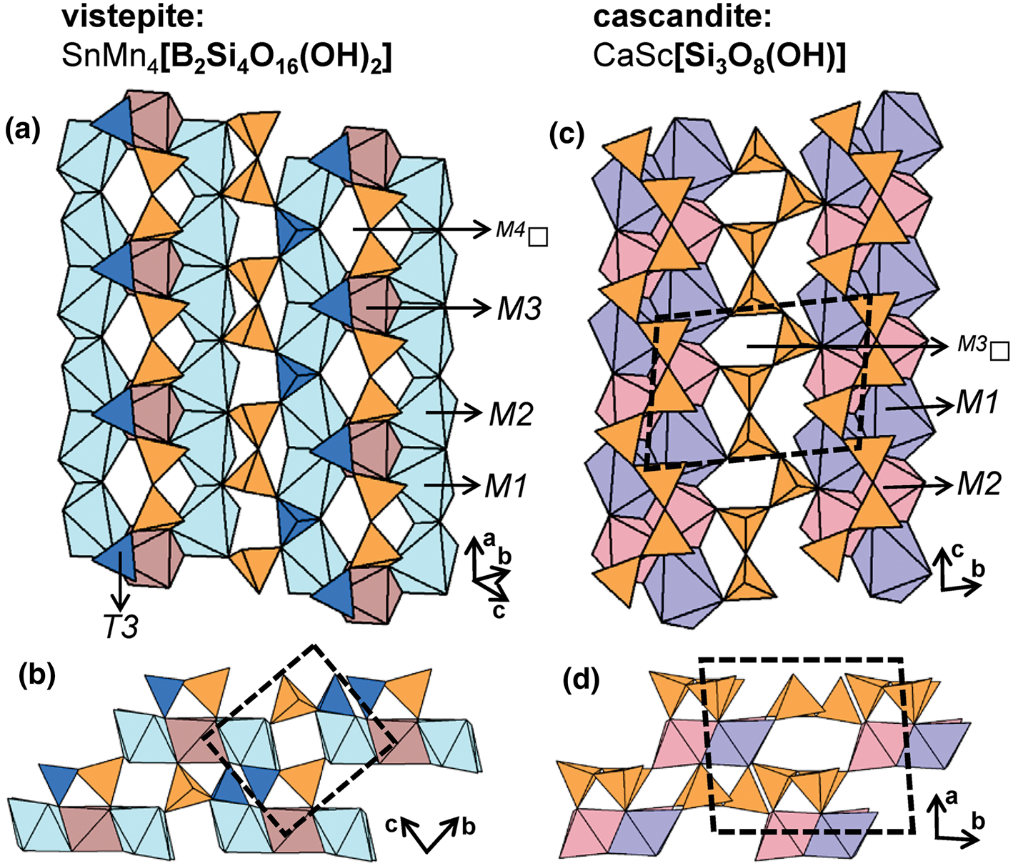
The general formula of the hydrous wollastonite-group minerals can be written as [M3(M1,M2)2(Si3O8(OH)], where the M3 site is occupied either by Na+ or Li+, and M1 and M2 are occupied by Ca2+, Mn2+, Y3+, Sn2+ and Sc3+ (Takéuchi et al., Reference Takéuchi, Koto and Yamanaka1976a,Reference Takéuchi, Kudoh and Yamanakab; Mellini et al., Reference Mellini, Merlino, Orlandi and Rinaldi1982; Hybler et al., Reference Hybler, Petříček, Jurek, Skála and Císařová1997; Nagashima et al., Reference Nagashima, Imaoka, Fukuda and Pettke2018). The M1 and M2 octahedra are typically occupied by Ca2+ and Mn2+, and form ribbons two polyhedra wide. Unlike the anhydrous varieties, ribbons of octahedra are linked to each other by M3 cations, forming sheets parallel to (101). In pectolite, M1 and M2 are occupied by Ca2+ and M3 is occupied by Na+ (Figs 13a,b). In barrydawsonite-(Y), M1 is occupied by Ca2+, M2 is occupied by Na+ and Y3+ (+REE), and M3 is occupied by Na+. In schizolite, M1 and M2 are occupied by Ca2+ and Mn2+, respectively, and M3 is occupied by Na+ (Figs 13c,d). In murakamiite (Figs 13e,f) and tanohataite (Figs 13g,h) M1 and M2 are occupied by Ca2+ and Mn2+, respectively, and M3 is occupied by Li+. In serandite, M1 and M2 are occupied by Mn2+ and M3 is occupied by Na+ (Figs 13i,j). In vistepite, the T3 site is occupied by B3+, and ribbons are three octahedra wide. Unlike most hydrous wollastonite-group minerals, adjacent ribbons of octahedra are not linked by Na+ or Li+ to form sheets. It follows that the vistepite structure more closely resembles that of bustamite and mendigite despite containing (OH)− groups. Here, M1 and M2 are occupied by Mn2+, M3 is occupied by Sn2+ and M4 is vacant (Figs 14a,b). In cascandite, M1 is occupied by Ca2+, M2 is occupied by Sc3+ and M3 is vacant (Figs 14c,d). In general, hydrous wollastonite-group minerals contain one (OH)− group that acts as a bridging anion between (SiO3(OH)−)3− tetrahedra (T1) and (CaO5(OH−))9− octahedra (M1); a more detailed discussion of hydrogen bonding in these minerals is given by Nagashima et al. (Reference Nagashima, Imaoka, Fukuda and Pettke2018).
The structure of (a, b) pectolite, (c, d) schizolite, (e, f) murakamiite, (g, h) tanohataite and (i, j) serandite viewed (a, c, e, g, i) orthogonal to the b-axis and (b, d, f, h, j) along the b-axis. M-site labels in (a) are also applicable to (c), (e), (g) and (i) and fine dashed black lines outline the unit cell. The H atoms associated with (OH)− groups have been omitted for clarity.
The structure of vistepite viewed (a) orthogonal to the a-axis and (b) along the a-axis, T 3[BO4] tetrahedra are shown in dark blue. The structure of cascandite projected (c) onto (100) and (d) along the c-axis. Fine dashed black lines outline the unit cell and H atoms associated with (OH)– groups have been omitted for clarity.
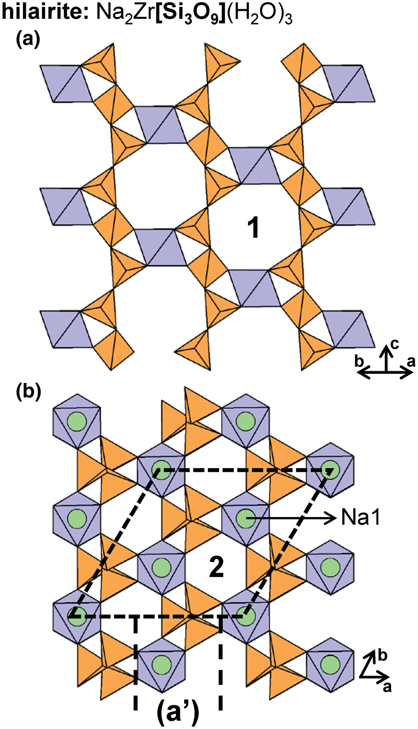
In hilairite, 2T3 chains extend along the c-axis and link to isolated Zr4+-octahedra to form an open framework (Figs 15a,b). Zr4+-octahedra occur in rows that extend along the c-axis, forming channels that are partly occupied by Na+ (Na1 and Na2) and (H2O) groups; these channels are labelled 1 in Fig. 15a. Figure 15b shows the position of Na1 atoms and channels labelled 2 that contain Na2 atoms and (H2O) groups. Other members of the hilairite group include calciohilairite, komkovite, sazykinaite-(Y), pyatenkoite-(Y) and synthetic K+-, Rb+-, Pb2+-, Sr2+-, Ba2+-, Ca2+- and Cs+-exchanged analogues of hilairite (Pekov et al., Reference Pekov, Chukanov, Kononkova and Pushcharovsky2003, Reference Pekov, Grigorieva, Zubkova, Turchkova and Pushcharovsky2010a; Zubkova et al., Reference Zubkova, Pekov, Turchkova, Pushcharovskii, Merlino, Pasero and Chukanov2007, Reference Zubkova, Kolitsch, Pekov, Turchkova, Vigasina, Pushcharovsky and Tillmans2009a) (Table 4).
The structure of hilairite projected (a) orthogonal to the c-axis and (b) along the c-axis. Channel 1 in (a) is occupied by Na1, Na2 and (H2O) groups and channel 2 in (b) is occupied by Na2 and (H2O) groups. The (H2O) groups, Na1 and Na2 in (a) and (H2O) groups and Na2 in (b) have been omitted for clarity. Fine dashed black lines outline the unit cell.
The 2T3 chain in umbite is geometrically distinct from the 2T3 chain in wollastonite- and the hilairite-group minerals. In umbite, chains extend along the c-axis and link to isolated Zr4+-octahedra (Fig. 16a), forming an open framework that contains channels that also extend along the c-axis, resembling hilairite-group minerals (Figs 15a–b). In umbite, K2 atoms and (H2O) groups occur in channels labelled 1 and K1 atoms occur within channels labelled 2 in Fig. 16b. In paraumbite, the H+-exchanged variety of umbite, the K1 site is partly occupied by H+ and in synthetic Cs+-exchanged umbite, Cs+ partly occupies the K1 site (Khomyakov et al., Reference Khomyakov, Voronkov, Kobyashev and Polezhaeva1983a; Fewox et al., Reference Fewox, Clearfield and Celestian2011). Kamenevite is the Ti4+-analogue of umbite and kostylevite is a monoclinic polymorph of umbite.
The structure of umbite projected (a) onto (010) and (b) along the c-axis. In (b), channel 1 is occupied by K2 and (H2O) groups and channel 2 is occupied by K1. The (H2O) groups, K1 and K2 atoms have been omitted for clarity. Fine dashed black lines outline the unit cell.

Foshagite, hillebrandite, jennite, ‘metajennite’, plombièrite (tobermorite-14Å), riversideite (tobermorite-9.3Å) and whelanite can be chemically classified as calcium–silicate–hydrates (C–S–H minerals) (Table 4) and have received considerable attention due to their structural and compositional similarities to the tobermorite-group minerals and their role in the hydration of Portland cement (Vigfusson, Reference Vigfusson1931; Gard and Taylor, Reference Gard and Taylor1976; Taylor, Reference Taylor1992; Cong and Kirkpatrick, Reference Cong and Kirkpatrick1996; Richardson, Reference Richardson2008; Meller et al., Reference Meller, Kyritsis and Hall2009). Synthetic C–S–H phases produced by cement chemists are often poor quality and not suitable for X-ray diffraction analysis. Consequently, natural analogues of such phases are studied instead which correspond to many of the 2T3, C–S–H minerals described here. In foshagite, 2T3 chains link to ribbons of (CaO4(OH)2)8−- and (CaO5(OH))9−-octahedra (Ca1–Ca4) (Fig. 17a). Ribbons four octahedra wide occur in layers parallel to (101) that alternate with layers of 2T3 chains (Fig. 17b), an arrangement that is similar to that of the wollastonite-group minerals (Figs 11e–f). In hillebrandite, 2T3 chains occupy and extend along tunnels in a framework of (Ca(O,OH)6)-octahedra and (Ca(O,(OH))7)-polyhedra.
The structure of (a, b) foshagite and (c, d) jennite viewed (a, c) orthogonal to the b-axis and (b, d) along the b-axis. The structure of plombièrite (tobermorite-14Å) projected (e) onto (100) and (f) along the b-axis. In (f), layers that contain 2T 3 chains are labelled T, layers that contain sheets of Ca2+-polyhedra are labelled O and layers that contain interstitial Ca2+-polyhedra and (H2O) groups are labelled I. Fine dashed black lines outline the unit cell which is halved along the c-axis in (f). The H atoms associated with (OH)− and (H2O) groups have been omitted for clarity.

In jennite, 2T3 chains extend along the b-axis and link to a framework of Ca2+-octahedra and [7]Ca2+-polyhedra (Ca1–Ca5). This framework consists of ribbons of (CaO4(OH)2)8−-octahedra that extend along the b-axis (Ca1 and Ca3) and are cross-linked to adjacent ribbons by isolated (CaO2(H2O)4)2−-octahedra (Ca5), forming sheets parallel to (001) (Fig. 17c). These sheets link along the a-axis via ribbons of (CaO3(OH)2(H2O))6−- and (CaO4(OH)2(H2O))8−-polyhedra (Ca2 and Ca4, respectively) (Fig. 17d). Jennite contains four transformer (H2O)t groups and three (OH)− groups.
The 2T3 [Si3O8(OH)]5− chains in plombièrite (tobermorite-14Å) link to sheets of (CaO6(OH))11−- (Ca1) and (CaO6(H2O))10−-polyhedra (Ca2) that are parallel to (100), forming layers with the composition [Ca4Si6O16(OH)2(H2O)2]2− (Fig. 17e). These layers link along the c-axis via chains of (CaO2(H2O)4)-octahedra (Ca3) that extend along the b-axis, parallel to 2T3 chains (Fig 17f). Plombièrite contains one (OH)− group that bridges (SiO3(OH)−)3−-tetrahedra and (CaO6(OH))11−-polyhedra (Ca1). Plombièrite also contains three (H2O)t and two (H2O)z groups that bond to interlayer Ca3 atoms, a layer that separates adjacent 2T3 chains and prevents them from polymerising and forming 2T23T4 [Si6O16]8− ribbons as in tobermorite-11Å (see below). In riversideite (tobermorite-9.3Å),2T3 [Si3O8(OH)]5− chains link to similar sheets of (CaO6(OH))11−-polyhedra, Ca2+-octahedra and [7]Ca2+-polyhedra but occur within a structure that is much more condensed due to a lower H2O content. For a more detailed description of hydrated C–S–H minerals, refer to the section on tobermorite-11Å. In both plombièrite and riversideite (tobermorite-group minerals), the following stacking sequence is observed; OTITOTIT, where ‘O’ represents a layer of Ca2+-polyhedra, ‘T’ a layer containing 2T3 chains and ‘I’, an interstitial layer of (H2O) groups and Ca2+-polyhedra that may or may not be present depending on the hydration state (Fig. 17f). In whelanite, the stacking sequence is OTCTOTCT (Fig. 18a), where ‘O’ represents a layer of (CaO6(OH,H2O))-polyhedra, ‘T’ is a layer containing 2T3 chains, and ‘C’ is a layer of (Cu(O,(OH))6)- and (Ca(O,(OH))6)-octahedra. In whelanite, the TCT block has OD character with two overlapping, half-occupied 2T3 chains in which all T sites (Si1a, Si1b and Si2) and anions involved in Si–O–Si linkages are half occupied; anions associated with Si4+-tetrahedra but not involved in Si–O–Si linkages are half occupied by O2− and half-occupied either by (OH)− or by (H2O). Despite chemical, spectroscopic and structural evidence for (CO3)2− groups in whelanite, its position in the structure has yet to be determined due to problems of disorder. Kampf et al. (Reference Kampf, Mills, Merlino, Pasero, McDonald, Wray and Hindman2012) provide a detailed description of both MDO polytypes and their OD characteristics. Figure 18b shows the structure of whelanite in which both overlapping, 2T3 chains are shown, one in red and the other in orange.
The structure of whelanite projected (a) along the b-axis and (b) onto (100). In (a), the TOTCTOT stacking sequence is labelled and in (b) one of the overlapping, half-occupied 2T3 chains is shown as orange tetrahedra on the other chain is shown as red tetrahedra. Fine dashed black lines outline the unit cell and H atoms associated with (OH)− and (H2O) groups and C atoms associated with (CO3) groups have been omitted for clarity.

2T4 chains
The 2T4 [Si4O12]8− chain in batisite-group minerals (Table 5) contains four distinct Si4+-tetrahedra that form c-shaped tetramers (Figs 19a–d). In batisite-group minerals, 2T4 chains extend along the a-axis and link to chains of corner-sharing Ti4+-octahedra (Fig. 19e). Each Ti4+-octahedra links to four distinct 2T4 chains, and chains of octahedra and tetrahedra occur in layers that alternate along the a-axis. Batisite-group minerals also contain three sites A1, A2 and A3. In batisite, these sites are occupied by Ba2+, Na+ and Na+, respectively (Fig. 19f). In scherbakovite, A1 and A2 are occupied by K+ and A3 is occupied by Na+. In noonkanbahite, A1, A2 and A3 are occupied by Ba2+, K+ and Na+, respectively. Although the presence of (OH)− is only included in the ideal formula of scherbakovite (Table 5), there is evidence for partial occupancy of one O2− site by (OH)− in batisite and noonkanbahite (Uvarova et al., Reference Uvarova, Sokolova, Hawthorne, Liferovich, Mitchell, Pekov and Zadov2010; Zolotarev et al., Reference Zolotarev, Zhitova, Gabdrakhmanova, Krzhizhanovskaya, Zolotarev and Krivovichev2017).
(a, b, c) Tetrahedral representations of the 2T 4 chain in batisite-group minerals and (d) a ball-and-stick representation of the chain. The structure of batisite projected (e) onto (100) and (f) along the c-axis. Dashed black lines outline the geometrical repeat unit of the chain and fine dashed black lines outline the unit cell.

The 2T4 [Si4O12]8− chains in haradaite extend along the c-axis and are linked to each other along the b-axis by sheets of Sr2+-polyhedra (Sr1) (Fig. 20a). Chains are also linked along the c-axis by [5]V4+-polyhedra. Sheets of 2T4 chains and [5]V4+-polyhedra and sheets of Sr2+-polyhedra are parallel to (001) and alternate along the b-axis (Fig. 20b). In suzukiite, the Ba2+-analogue of haradaite, 2T4 chains are linked to each other by sheets of [11]Ba2+-polyhedra. In ohmilite, 2T4 chains extend along the b-axis and link to a complex layer of Ti4+-octahedra (M1) and Sr2+-polyhedra (Fig. 20c). Corner-sharing Ti4+-octahedra form chains that extend along the b-axis and link to two 2T4 chains, forming [Si8O24(Ti2O2)]12− ribbons. These ribbons link to each other along the a-axis by (SrO8(H2O))14−- (Sr1), (SrO6(H2O)2)10−- (Sr2) and (SrO7(H2O))12−-polyhedra (Sr3) (Fig. 20d). Ohmilite contains one (H2O)n and two (H2O)t groups. Mizota et al. (Reference Mizota, Komatsu and Chihara1983) have suggested that the substitution Ti4+ + O2− ↔ Fe3+ + OH− may be responsible for the partial occupancy of the M1 site by Fe3+ and the OH-stretch in the IR spectrum of ohmilite.
The structure of haradaite projected (a) onto (001) and (b) along the a-axis (b). The structure of ohmilite projected (c) onto (100) and (d) along the b-axis (c) and into the b-axis. Fine dashed black lines outline the unit cell and H atoms associated with (OH)− and (H2O) groups have been omitted for clarity.

In the OD structure of fukalite, six MDO polytypes are known; here we describe the fukalite structure based on the MDO1 polytype. Here, 2T4 chains are strongly modulated, resembling chains in batisite, haradaite and ohmilite. In fukalite, there are two types of layers that are parallel to (100) and alternate along the b-axis (Fig. 21a). Layer 1 consists of planar sheets of (CaO6(OH))11−-polyhedra (Ca1–Ca4) and layer 2 consists of ribbons of (CaO4(OH)2)8−- and (CaO5(OH)2)10−-polyhedra (Ca5–Ca8) that link along the c-axis to form a modulated sheet. Layers are linked along the b-axis by (CO3)2− groups and 2T4 chains that extend along the a-axis (Fig. 21b). There are four (OH)− groups that bridge Ca2+-polyhedra of layer 1 to Ca2+-polyhedra of layer 2.
The structure of fukalite projected (a) along the a-axis and (b) onto (001). In (a), (CO3) groups are shown in dark grey and H atoms associated with (OH)− groups are omitted for clarity. Fine dashed black lines outline the unit cell.

The 2T4 chain in taikanite (Figs 22a–d) is geometrically distinct from the 2T4 chain in the batisite-group minerals. In taikanite, Si4+-tetrahedra form chains that extend along the b-axis and link to chains of edge-sharing [8]Sr2+-polyhedra that also extend along the b-axis (Fig. 22e). These chains link along the a-axis via chains of edge-sharing Mn2+-octahedra that extend along the c-axis and via [8]Ba2+-polyhedra. In taikanite, [8]Sr2+- and [8]Ba2+-polyhedra and 2T4 chains occur in layers that alternate along the c-axis (Fig. 22f). The 2T4 [Si4O10(OH)2]6− chain in krauskopfite contains (Si(O,OH)4)-tetrahedra but does not consist of c-shaped tetramers like the chains in batisite-group minerals (Fig. 19b); instead chains are more extended (linear) (Figs 23a–d). In krauskopfite, chains link to chains of edge-sharing [8]Ba2+-polyhedra (Fig. 23e) that occur in layers parallel to (001) and alternate with layers of 2T4 chains (Fig. 23f). Krauskopfite contains six H+ ions, two of which are associated with (OH)− groups and form acid silicate groups and four are associated with (H2O) groups bonded to [8]Ba2+-polyhedra.
(a, b, c) Tetrahedral representations of the 2T 4 chain in taikanite and (d) a ball-and-stick representation of the chain. The structure of taikanite projected (e) onto (001) and (f) along the b-axis. Dashed black lines outline the geometrical repeat unit of the chain and fine dashed black lines outline the unit cell.

(a, b, c) Tetrahedral representations of the 2T 4 chain in krauskopfite and (d) a ball-and-stick representation of the chain. The structure of krauskopfite projected (e) onto (100) and (f) along the c-axis. Dashed black lines outline the geometrical repeat unit of the chain and fine dashed black lines outline the unit cell. The H atoms associated with (OH)− and (H2O) groups have been omitted for clarity.

Balangeroite and gageite are asbestiform minerals that have monoclinic (2M) and triclinic (1A) polytypes due to their OD character (Bonaccorsi et al., Reference Bonaccorsi, Ferraris and Merlino2012) (Table 5). Both minerals contain 2T4 chains that show a higher degree of chain extension than other 2T4 chains (Figs 24a–d). Chains extend along the b-axis and link to a framework of predominately Mg2+-, Mn2+- and Fe2+-octahedra. Balangeroite and gageite contain twenty-four distinct octahedrally coordinated M-sites that polymerise to form [1] a ribbon of edge-sharing octahedra, and [2] a column of edge-sharing octahedra. These units extend along the b-axis and each occurs in two crystallographically distinct orientations: sites M1–M12 comprise the ribbon and sites M13–M24 comprise the column (Fig. 24e). Here, there are eight distinct Si4+-tetrahedra that form 2T4 chains that occupy channels in the framework of octahedra. Each 2T4 chain links to two crystallographically distinct columns (Fig. 24f) and to one ribbon (Fig. 24g). Balangeroite and gageite contain 20 (OH)− groups that each link to three M-site cations. The Ni–Fe analogue of balangeroite occurs as intergrowths in antigorite serpentinite (Evans and Kuehner, Reference Evans and Kuehner2011).
(a, b, c) Tetrahedral representations of the 2T 4 chain in balangeroite and (d) a ball-and-stick representation of the chain. The structure of balangeroite projected (e) along the b-axis and (f, g) the two modes of linkage between 2T 4 chains and the interstitial structure projected onto (001). Dashed black lines outline the geometrical repeat unit of the chain and fine dashed black lines outline the unit cell. The H atoms associated with (OH)− groups have been omitted for clarity.

Many novel, synthetic compounds contain 2T4 chains such as BaUO2[Si2O6] (Plaisier et al., Reference Plaisier, Ijdo, de Mello Donego and Blasse1995), NaY[Si2O6] (Toebbens et al., Reference Toebbens, Kahlenberg and Kaindi2005), Cu3Na2[Si4O12] (Kawamura and Kawahara, Reference Kawamura and Kawahara1976), Ca3Mn2O2[Si4O12] (Moore and Araki, Reference Moore and Araki1979) and NaGd[P4O12] (Amami et al., Reference Amami, Fend and Trabelsi-Ayedi2005).
2T5 chains
The rhodonite-group minerals rhodonite, ferrorhodonite and vittinkiite (Table 5) contain 2T5 chains in which Si4+-tetrahedra link to form c-shaped trimers that are linked by [Si2O7]6− dimers (Figs 25a–d). Here, 2T5 chains and ribbons of higher coordination polyhedra (M1–M5) occur in alternating layers that are parallel to (100).
(a, b, c) Tetrahedral representations of the 2T 5 chain in rhodonite-group minerals and (d) a ball-and-stick representation of the chain. The structure of rhodonite viewed (e) orthogonal to [110] and (f) along [110]. Dashed black lines outline the geometrical repeat unit of the chain.
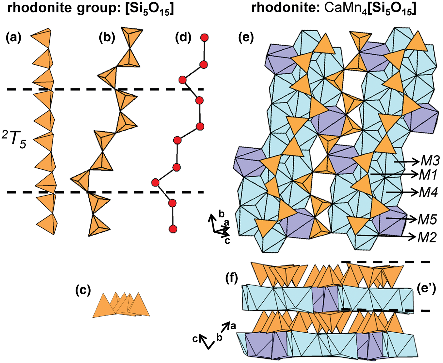
The general formula for rhodonite-group minerals may be written as M 5M 1–3M 4[T 5O15], and a new nomenclature scheme was recently provided by Shchipalkina et al. (Reference Shchipalkina, Pekov, Chukanov, Biagioni and Pasero2019b). In these structures, 2T5 chains extend along [110] and link adjacent ribbons of higher-coordination polyhedra. In vittinkiite, ideally Mn5[Si5O15], all M sites are occupied by Mn2+. However, such compositions are uncommon, as most rhodonite-group minerals show considerable chemical variability over the M sites (Mason, Reference Mason1975), incorporating Ca2+, Fe2+, Mg2+ and Zn2+ in addition to Mn2+. The [7]-coordinated M5-site in rhodonite is dominated by Ca2+ (Figs 25e,f) and as a result, the formula for rhodonite is ideally CaMn4[Si5O15]. In ferrorhodonite, M4 is occupied by Fe2+, M1–M3 are occupied by Mn2+, and M5 is occupied by Ca2+. Figures 26a–f highlights M-site substitution in these three minerals. Rhodonite-group minerals with significant Zn2+ and Mg2+ have been reported and details on the ordering of M-site cations and the effects of composition on rhodonite structures are given by Peacor and Niizeki (Reference Peacor and Niizeki1963), Peacor et al. (Reference Peacor, Essene, Brown and Winter1978a), Ohashi and Finger (Reference Ohashi and Finger1975), Nelson and Griffen (Reference Nelson and Griffen2005), Leverett et al. (Reference Leverett, Williams and Hibbs2008) and Shchipalkina et al. (Reference Shchipalkina, Chukanov, Pekov, Aksenov, McCammon, Belakovskiy, Britvin, Koshlyakova, Schäfer, Scholz and Rastsvetaeva2017). The compositional range of the rhodonite-group minerals overlaps strongly with that of the bustamite-group minerals and in a minor way with that of pyroxmangite (Shchipalkina et al., Reference Shchipalkina, Pekov, Chukanov, Biagioni and Pasero2019b).
The structure of (a, b) vittinkiite, (c, d) rhodonite and (e, f) ferrorhodonite viewed (a, c, e) orthogonal to [110] and (b, d, f) along [110]. M-site labels in (a) are also applicable to (c) and (e).

The general formula of lithiomarsturite, marsturite, nambulite and natronambulite can be written as M 5M 4M 1–3[T 5O14(O,OH)] (Table 5). The T1 tetrahedra in lithiomarsturite and marsturite and the T4 tetrahedra in natronambulite and nambulite are acid silicate groups; (SiO3(OH))3−, and 2T5 chains extend along [110]. The M1–M3 sites in marsturite and the M1 and M3 sites in lithiomarsturite are occupied by Mn2+, the M5 site is occupied by Na+ and Li+, respectively, and the M4 site is occupied by Ca2+ in both minerals. In marsturite, [7]Ca2+-polyhedra (M4) and (NaO7(OH))14−-polyhedra (M5) link adjacent ribbons of M1–M3-octahedra to form sheets that alternate with layers of 2T5 chains (Figs 27a,b). In lithiomarsturite, the M5 site is occupied by Li+ that forms (LiO4(OH))8−-polyhedra and the M2 site is occupied by Ca2+ that forms (CaO5(OH))9−-octahedra (Figs 27c,d). Although the coordination of Li+ in lithiomarsturite, nambulite and natronambulite is not yet agreed upon, Nagashima et al. (Reference Nagashima, Armbruster, Kolitsch and Pettke2014a) used bond-valence arguments to show that Li+ is probably [5]-coordinated; here we show Li+ as a [5]-coordinated cation (Fig. 27c). In nambulite and natronambulite, the octahedrally coordinated M1–M3 sites are occupied by Mn2+, the M4 site is occupied by [7]Mn2+ and the M5 site is occupied by Li+ that forms (LiO4(OH))8−-polyhedra in nambulite (Figs 27e,f), and by Na+ that forms (NaO7(OH))14−-polyhedra in natronambulite (Figs 27g,h). In nambulite and natronambulite, the M4 and M5 polyhedra link adjacent ribbons of M1–M3 octahedra to form a sheet similar to that in marsturite and lithiomarsturite. In santaclaraite, T1 is an (SiO3(OH))3−-tetrahedron and 2T5 chains link to rhodonite-type ribbons of (Mn2+(O,(OH),H2O)6)-octahedra and Ca2+-polyhedra.
The structure of (a, b) marsturite, (c, d) lithiomarsturite, (e, f) nambulite and (g, h) natronambulite viewed (a, c, e, g) orthogonal to [110] and (b, d, f, h) along [110]. Here, M-site labels in (a) are also applicable to (c), (e) and (g) and H atoms associated with (OH)− groups have been omitted for clarity.

The general formula for the babingtonite-group minerals can be written as A 2M 1M 2[T 5O14(OH)] (Table 5). The geometrical repeat unit of the 2T5 [Si5O14(OH)]9− chain in babingtonite contains four Si4+-tetrahedra and one (SiO3(OH))3−-tetrahedron. These 2T5 chains link to sheets of [8]Ca2+-polyhedra (Ca1 and Ca2) and Fe2+-octahedra (M1 and M2) that are parallel to (110) (Figs 28a,b). In manganbabingtonite, the M1 site is occupied by Mn2+ and in scandiobabingtonite M2 is occupied by Sc3+. Various synthetic compounds containing 2T5 chains have been described including Mn2+5[Si5O15] (synthetic vittinkiite) and LiMn2+4[Si5O14(OH)] (synthetic nambulite) (Ito, Reference Ito1972).
The structure of babingtonite projected (a) onto (001) and (b) orthogonal to the c-axis. Fine dashed black lines outline the unit cell and H atoms associated with (OH)– groups have been omitted for clarity.

2T6 chains
The 2T6 [Si6O18]12− chains in stokesite, georgechaoite and gaidonnayite are modulated in two directions and have been described geometrically as spiral chains (Vorma, Reference Vorma1963; Chao, Reference Chao1985; Yuan et al., Reference Yuan, Guowu and Guangming2017). These 2T6 chains extend along the b-axis and are modulated along both the c-axis and the a-axis (Figs 29a–d). Chains of tetrahedra link to chains of Sn2+-octahedra and (CaO4(H2O)T2)6−-octahedra (Fig. 29e), and adjacent chains of octahedra are linked along the c-axis by 2T6 chains (Fig. 29f). In georgechaoite and gaidonnayite, 2T6 chains extend along [101] and are modulated along the b-axis (Figs 30a–d). Chains of tetrahedra link to chains of (NaO4(H2O)T2)7−- and (ZrO6)8−-octahedra that are cross-linked by (KO4(H2O)2)7−-octahedra in georgechaoite (Figs 30e,f) and by (NaO4(H2O)T2)7−-polyhedra in gaidonnayite. In gaidonnayite, Na sites contain minor amounts of K+ that may be substituted by Cs+ in synthetic Cs-exchanged varieties such as Cs4Zr2[Si6O18](H2O)4 (Celestian et al., Reference Celestian, Lively and Xu2019). Synthetic K8Sr2[Si6O18] also contains geometrically similar 2T6 chains (Kahlenberg et al., Reference Kahlenberg, Kaindl and Sartory2007).
(a, b, c) Tetrahedral representations of the 2T 6 chain in stokesite and (d) a ball-and-stick representation of the chain. The structure of stokesite projected (e) onto (001) and (f) along the a-axis. The H atoms of both (H2O) groups are shown as red circles. Dashed black lines outline the geometrical repeat unit of the chain and fine dashed black lines outline the unit cell.

(a, b, c) Tetrahedral representations of the 2T 6 chain in georgechaoite and (d) a ball-and-stick representation of the chain. The structure of georgechaoite projected (e) onto (001) and (f) along the a-axis. Dashed black lines outline the geometrical repeat unit of the chain and fine dashed black lines outline the unit cell. The H atoms associated (H2O) groups have been omitted for clarity.

2T7 chains
Pyroxferroite and pyroxmangite are of particular interest as they are the only minerals that contain 2T7 chains (Figs 31a–d). Chains of tetrahedra link to sheets of octahedra and [7]-coordinated polyhedra (M1–M7) that occur in layers that alternate with layers of 2T7 chains along [011] (Figs 31e,f). Compositions close to either end-member are rare; there is extensive Fe2+–Mn2+ solid-solution that also can incorporate significant amounts of Mg2+, Ca2+, Na+ and minor Al3+ and Cr3+. In pyroxmangite and pyroxferroite, M1–M4 are octahedrally coordinated, M6 is [5]- or [6]-coordinated, and M5 and M7 are [7]-coordinated. In pyroxmangite, M1–M4 are typically occupied predominantly by Mn2+ with subordinate Mg2+ and Fe2+; however, Mg2+ dominates at M2–M4 in synthetic Mg-rich pyroxmangite (Finger and Hazen, Reference Finger and Hazen1978). The M6 site is preferentially occupied by Mg2+ but may also be occupied by Mn2+ and/or Fe2+, and M5 and M7 are occupied by Mn2+ with minor Mg2+ and Fe2+. In pyroxferroite, Ca2+ preferentially occupies the [7]-coordinated M5 and M7 sites, the M1–M4 sites are occupied by Fe2+ with subordinate Mn2+ and Ca2+, and the M6 site is preferentially occupied by Mg2+ but may also contain Mn2+ and/or Fe2+.
(a, b, c) Tetrahedral representations of the 2T 7 chain in pyroxmangite and (d) a ball-and-stick representation of the chain. The structure of pyroxmangite viewed (e) orthogonal to the c-axis and (f) along the c-axis. Dashed black lines outline the geometrical repeat unit of the chain and fine dashed black lines outline the unit cell.

2T9 chains
The 2T9 chain occurs only in synthetic ferrosilite III (Table 5) where it extends along the c-axis (Figs 32a–d). There are nine octahedrally coordinated sites (M1–M9) that are occupied by Fe2+ and form ribbons that extend parallel to [001]. The 2T9 chains and ribbons of Fe2+-octahedra occur in alternating layers (Figs 32e,f), comparable to the structures of pyroxmangite (Figs 31e,f) pyroxferroite and the rhodonite-group minerals (Figs 25e,f and 26a–f).
(a, b, c) Tetrahedral representations of the 2T 9 chain in synthetic ferrosilite III and (d) a ball-and-stick representation of the chain. The structure of synthetic ferrosilite III viewed (e) orthogonal to the c-axis and (f) along the c-axis. Dashed black lines outline the geometrical repeat unit of the chain and fine dashed black lines outline the unit cell.
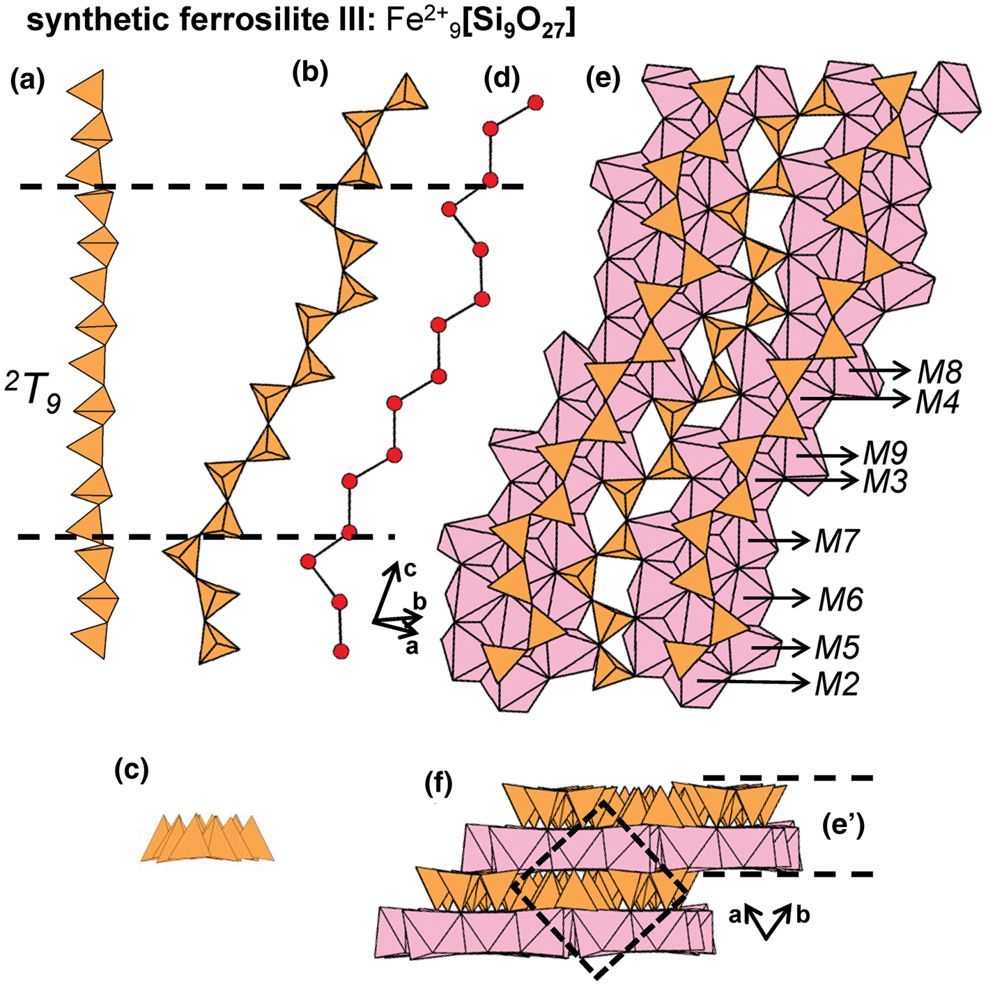
2T12 chains
The geometrical repeat unit of the chain in alamosite contains twelve Si4+-tetrahedra that polymerise to form 2T12 chains that extend parallel to [101]. The 2T12 chains are modulated in two directions, resulting in a spiral chain (Figs 33a–d) resembling the 2T6 chains in stokesite (Figs 29a–d). In alamosite, 2T12 chains link to spiral ribbons of [5]-, [7]- and [6]-coordinated Pb2+-polyhedra that occupy three sites: Pb1, Pb2 and Pb3 (Figs 33e,f).
(a, b, c) Tetrahedral representations of the 2T 12 chain in alamosite and (d) a ball-and-stick representation of the chain. The structure of alamosite projected (e) onto (010) and (f) along the c-axis. Pb1 and Pb2 atoms have been omitted for clarity. Dashed black lines outline the geometrical repeat unit of the chain and fine dashed black lines outline the unit cell.

2T24 chains
The 2T 24 chain occurs only in synthetic Na24Y8(Si24O72). The geometrical repeat unit of this chain contains twenty-four Si4+-tetrahedra that polymerise to form a spiral chain modulated along the a- and c-axes (Figs 34a–d). A complete structure description is given by Maksimov et al. (Reference Maksimov, Kalinin, Merinov, Ilyukhin and Belov1980).
(a, b, c) Tetrahedral representations of the 2T 24 chain in synthetic Na24Y8[Si24O72] projected (a) onto (100), (b) onto (001), (c) along the b-axis and (d) a ball-and-stick representation of the chain. Dashed black lines outline the geometrical repeat unit of the chain.

3Tr class
3T4 ribbons
The geometrical repeat unit of the ribbons in vinogradovite, paravinogradovite and bigcreekite (Table 6) contains four distinct tetrahedra that polymerise to form 3T4 ribbons (Figs 35a–c). Topologically, these 3V2 ribbons (Fig. 35d) are identical to many of the 3Tr ribbons described in the following sections. Vinogradovite and paravinogradovite contain 2T2 pyroxene-like chains in addition to 3T4 ribbons. Vinogradovite contains two distinct tetrahedra: T1 and T2; the T1 tetrahedra form the 2T2 chains and the T2 tetrahedra form the 3T4 ribbons. Paravinogradovite contains seven distinct Si4+-tetrahedra (T1–T7) and one Al3+-tetrahedra (T8): T1–T4 tetrahedra form the 2T2 chains and T5–T8 tetrahedra form the 3T4 ribbons. In vinogradovite, 2T2 chains and 3T4 ribbons extend along the c-axis and link to sheets of Ti4+-octahedra (M1) and [8]Na+-polyhedra (X1) that extend parallel to [001] (Fig. 36a). In Fig. 36b, channel 1 is occupied by Na+(and K+) ions (A1) and (H2O) groups (W1 and W2). In paravinogradovite, chains and ribbons of tetrahedra extend along the a-axis and link to sheets of [TiO4(OH)2]6−- (M1–M4) and [NaO5(OH)]10−-octahedra (X1–X2) that extend parallel to (100) (Fig. 36c). Due to its OD character, there are several partly occupied sites in paravinogradovite. As shown in Fig. 36d, channel 1 is partly occupied by Na+ (X3), resulting in a discontinuous sheet. Multiple partly occupied sites occur within channel 2, including W1–W3, A1–A4 (Na+) and A5 (K+). Paravinogradovite contains four H+ sites associated with (OH)− groups (Fig. 36d).
(a, b) Tetrahedral representation of the 3T4 ribbon in paravinogradovite projected (a) orthogonal to the a-axis (b) onto (010), (c) a ball-and-stick and (d) a graphical representation of the ribbon. The T8 site is occupied by Al3+. Dashed black lines outline the geometrical and topological repeat unit of the ribbon.
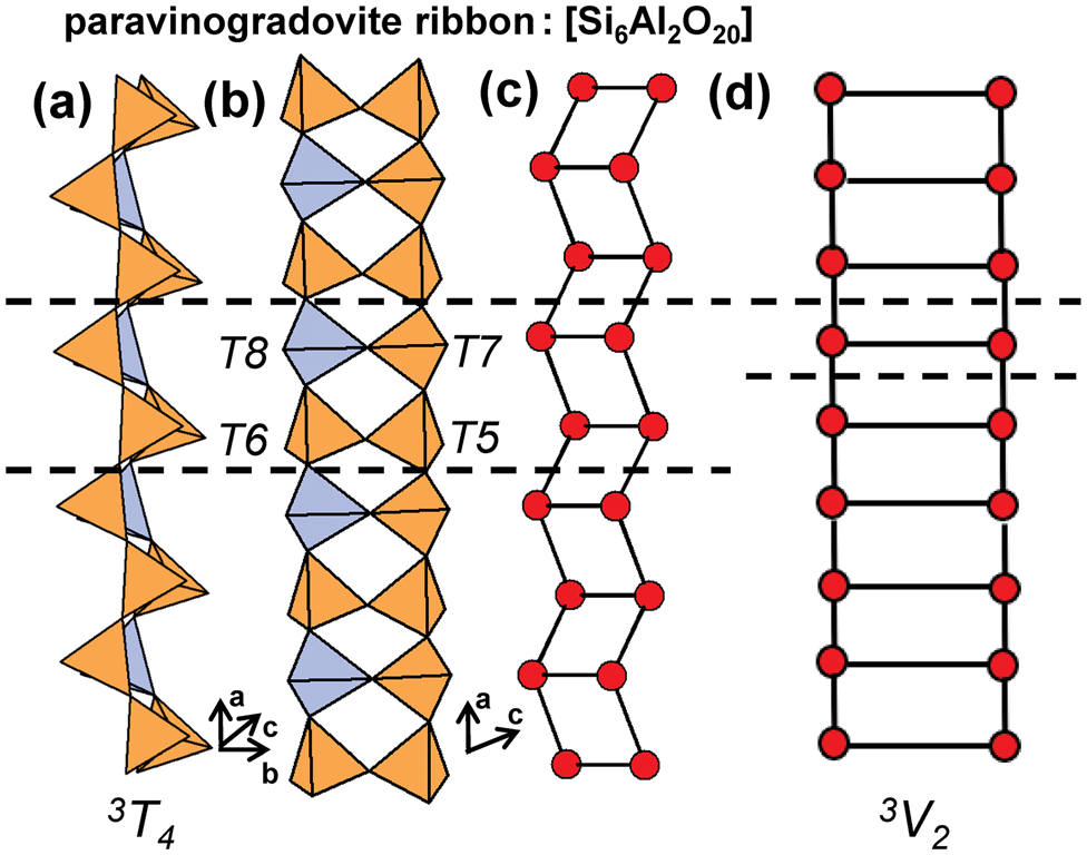
The structure of vinogradovite projected (a) onto (100) and (b) along the c-axis. In (b), channel 1 is occupied by Na(K)+-polyhedra and H atoms associated with (H2O) groups have been omitted for clarity. The structure of paravinogradovite projected (c) onto (001) and (d) along the a-axis. In (d), channel 1 is partly occupied by Na+-polyhedra and channel 2 is occupied by Na+-polyhedra and (H2O) groups which have been omitted for clarity. Paravinogradovite contains four H sites (H1–H4) associated with (OH)− that are shown as red circles. Fine dashed black lines outline the unit cell which is halved along the a-axis in (b).
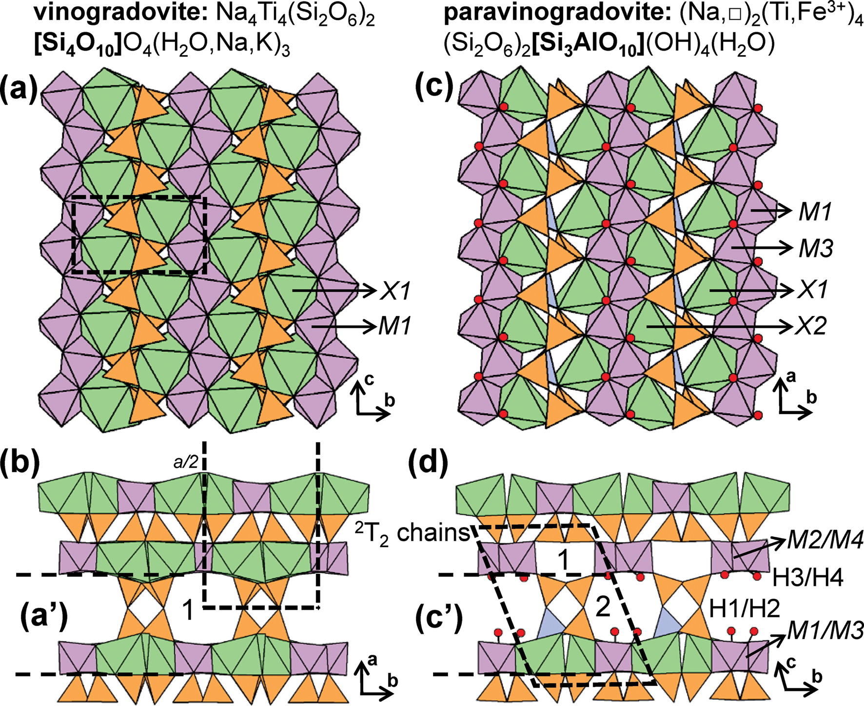
Minerals with 3Tr ribbons and tubes.

References: (1) Kalsbeek and Rønsbo (Reference Kalsbeek and Rønsbo1992), Rastsvetaeva et al. (Reference Rastsvetaeva, Simonov and Belov1968), Rastsvetaeva and Andrianov (Reference Rastsvetaeva and Andrianov1984); (2) Khomyakov et al. (Reference Khomyakov, Kulikova, Sokolova, Hawthorne and Kartashov2003); (3) Basciano et al. (Reference Basciano, Groat, Roberts, Gault, Dunning and Walstrom2001); (4) Völlenkle et al. (Reference Völlenkle, Wittmann and Nowotny1968); (5) Dörsam et al. (Reference Dörsam, Kahlenberg and Fischer2003); (6) Robinson and Fang (Reference Robinson and Fang1970); (7) Gatta et al. (Reference Gatta, Rotiroti, McIntyre, Guastoni and Nestola2008), Fang et al. (Reference Fang, Robinson and Ohya1972); (8) Cannillo et al. (Reference Cannillo, Rossi and Ungaretti1973), Zubkova et al. (Reference Zubkova, Ksenofontov, Kabalov, Chukanov, Nedelko, Pekov and Pushcharovsky2011); (9) Agakhanov et al. (Reference Agakhanov, Pautov, Karpenko, Sokolova, Abdu, Hawthorne, Pekov and Siidra2015); (10) Grigor'eva et al. (Reference Grigor'eva, Zubkova, Pekov, Kolitsch, Pushcharovsky, Vigasina, Giester, Dordević, Tillmanns and Chukanov2011); (11) Grigor'eva et al. (Reference Grigor'eva, Zubkova, Pekov, Kolitsch, Pushcharovsky, Vigasina, Giester, Dordević, Tillmanns and Chukanov2011); (12) Mellini and Merlino (Reference Mellini and Merlino1978), Hogarth et al. (Reference Hogarth, Chao, Plant and Steacy1974); (13) Brandão et al. (Reference Brandão, Rocha, Reis, dos Santos and Jin2009), Pozas et al. (Reference Pozas, Rossi and Tazzoli1975); (14) Golovachev et al. (Reference Golovachev, Drozdov, Kuz'min and Belov1971), Rozhdestvenskaya et al. (Reference Rozhdestvenskaya, Bannova, Nikishova and Soboleva2004); (15) Khomyakov et al. (Reference Khomyakov, Kurova and Nechelyustov1992), Karimova and Burns (Reference Karimova and Burns2007); (16) Aksenov et al. (Reference Aksenov, Rastsvetaeva, Chukanov and Kolitsch2014), Chukanov et al. (Reference Chukanov, Aksenov, Rastsvetaeva, Blass, Varlamov, Pekov, Belakovskiy and Gurzhiy2015b); (17) Rozhdestvenskaya and Nikishova (Reference Rozhdestvenskaya and Nikishova1998), Ghose and Wan (Reference Ghose and Wan1979); (18) Schmidmair et al. (Reference Schmidmair, Kahlenberg and Grießer2018); (19) Brandão et al. (Reference Brandão, Rocha, Reis, dos Santos and Jin2009); (20) Kornev et al. (Reference Kornev, Maksimov, Lider, Ilyukhin and Belov1972), Kawamura and Kawahara (Reference Kawamura and Kawahara1977), Durand et al. Reference Durand, Vilminot, Richard-Plouet, Derory, Lambour and Drillon1997, Cadoni and Ferraris (Reference Cadoni and Ferraris2011); (21) Peacor and Buerger (Reference Peacor and Buerger1962b), Pyatenko and Pudovkina (Reference Pyatenko and Pudovkina1960), Wagner et al. (Reference Wagner, Parodi, Semet, Robert, Berrahma and Velde1991), Kolitsch and Tillmanns (Reference Kolitsch and Tillmanns2004), Schingaro et al. (Reference Schingaro, Mesto, Lacalamita, Scordari, Kaneva and Vladykin2017); (22) Kolitsch and Tillmanns (Reference Kolitsch and Tillmanns2004); (23) Siidra et al. (Reference Siidra, Krivovichev and Depmeier2009); (24) Hung et al. (Reference Hung, Wang, Kao and Lii2003); (25) Merlino (Reference Merlino1969), Bagiński et al. (Reference Bagiński, Macdonald, White and Jeżak2018), Merlino and Biagioni (Reference Merlino and Biagioni2018); (26) Johnsen et al. (Reference Johnsen, Nielsen and Sotofte1978), Upton et al. (Reference Upton, Hill, Johnsen and Petersen1978); (27) Dunn et al. (Reference Dunn, Rouse, Cannon and Nelen1977), Ghose and Wan (Reference Ghose and Wan1978); (28) Rastsvetaeva et al. (Reference Rastsvetaeva, Rozenberg, Khomyakov and Rozhdestvenskaya2003), Dorfman et al. (Reference Dorfman, Rogachev, Goroshchenko and Uspenskaya1959), Rozhdestvenskaya et al. (Reference Rozhdestvenskaya, Nikishova, Bannova and Lasebnik1987); (29) Rastsvetaeva et al. (Reference Rastsvetaeva, Rozenberg, Khomyakov and Rozhdestvenskaya2003), Khomyakov et al. (Reference Khomyakov, Nechelyustov, Krivokoneva, Rastsvetaeva, Rozenberg and Rozhdestvenskaya2009); (30) Rozhdestvenskaya et al. (Reference Rozhdestvenskaya, Nikishova and Lazebnik1996), Nikishova et al. (Reference Nikishova, Lazebnik, Rozhdestvenskaya, Emelyanova and Lazebnik1996); (31) Rozhdestvenskaya and Evdokimov (Reference Rozhdestvenskaya and Evdokimov2006), Scott (Reference Scott1976), Rozhdestvenskaya et al. (Reference Rozhdestvenskaya, Nikishova, Bannova and Lasebnik1987), Kaneva et al. (Reference Kaneva, Lacalamita, Mesto, Schingara, Scordari and Vladykin2014); (32) Men'shikov (Reference Men'shikov1984), Konev et al. (Reference Konev, Vorobiev, Paradina and Sapozhnikov1987), Rozhdestvenskaya et al. (Reference Rozhdestvenskaya, Mugnaioli, Schowalter, Schmidt, Czank, Depmeier and Rosenauer2017); (33) Schafer and Schleid (Reference Schäfer and Schleid2007); (34) Hung et al. (Reference Hung, Wang, Kao and Lii2003); (35) Kahlenberg and Manninger (Reference Kahlenberg and Manninger2014); (36) Rozhdestvenskaya et al. (Reference Rozhdestvenskaya, Mugnaioli, Czank, Depmeier, Kolb and Merlino2011), Chiragov and Shirinova (Reference Chiragov and Shirinova2004), Matesanz et al. (Reference Matesanz, Garcia-Guinea, Crespo-Feo, Lopez-Arce, Valle-Fuentes and Correcher2008), Rozhdestvenskaya et al. (Reference Rozhdestvenskaya, Mugnaioli, Czank, Depmeier, Kolb, Reinholdt and Weirich2010), Rozhdestvenskaya et al. (Reference Rozhdestvenskaya, Kogure, Abe and Drits2009); (37) Sassi et al. (Reference Sassi, Gramlich, Miéhé-Brendié, Josien, Paillaud, Benggedach and Patarin2003); (38) Moore et al. (Reference Moore, Sen Gupta, Schlemper and Merlino1987).
* Indicates the cTr expression of an additional structural unit including a chain, ribbon, tube, cluster or sheet of [TO4]n– tetrahedra in the respective mineral.
The 3T 4 ribbon in bigcreekite extends along the a-axis and links to modulated sheets of (BaO2(H2O)7)2−-polyhedra that are parallel to (100) (Fig. 37a). 3T4 ribbons and sheets of Ba2+-polyhedra alternate along the b-axis (Fig. 37b). This type of 3T4 ribbon occurs in several synthetic compounds including Li4(SiGe3O10) and Cs2H2(Si4O10) (Völlenkle et al., Reference Völlenkle, Wittmann and Nowotny1968; Dörsam et al., Reference Dörsam, Kahlenberg and Fischer2003).
The structure of bigcreekite projected (a) onto (001) and (b) along the a-axis. Fine dashed black lines outline the unit cell and H atoms associated with (H2O) groups have been omitted for clarity.
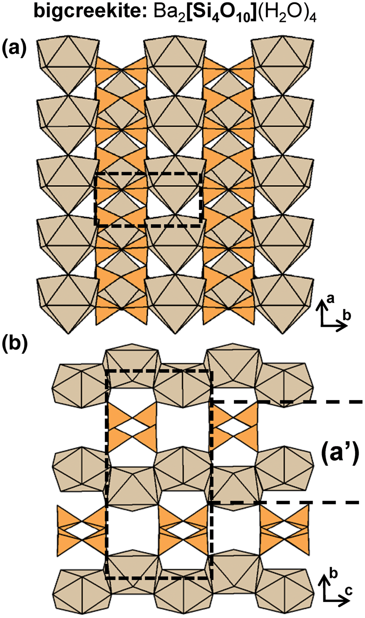
3T6 ribbons
The epididymite group includes epididymite, eudidymite, elpidite and yusupovite (Table 6), all of which contain 3T6 [Si6O15]6− ribbons with the vertex degree 3V2 (Figs 38a–d). In the two dimorphs, epididymite and eudidymite, ribbons extend along [001] and are linked to adjacent chains along [100] and [010] by pairs of edge-sharing Be2+-tetrahedra, forming an open-framework of tetrahedra. Cavities within this framework are occupied by (H2O) and Na+ that forms (NaO6(H2O))11−- and (NaO5(H2O)2)9−-polyhedra in epididymite and eudidymite, respectively. Although both minerals contain frameworks of tetrahedra rather than ribbons of tetrahedra, they have been added to Table 6 for purposes of comparison. In elpidite, 3T6 ribbons extend along [100] and are linked to each other along [010] and [001] by Zr4+- and (NaO4(H2O)2)7−-octahedra rather than Be2+-tetrahedra, forming an open-framework that contains 3T6 ribbons. Cavities within this framework are occupied by (H2O) and Na+ that forms (NaO6(H2O))11−-polyhedra (Figs 39a,b). In yusupovite, the monoclinic dimorph of elpidite, 3T6 ribbons extend along [010] and there are six T sites rather that three as in the other epididymite-group minerals. Various synthetic, K+- and Rb+-exchanged analogues of elpidite (K2Zr[Si6O15](H2O) and Rb2Zr[Si6O15](H2O)) have been described by Grigor'eva et al. (Reference Grigor'eva, Zubkova, Pekov, Kolitsch, Pushcharovsky, Vigasina, Giester, Dordević, Tillmanns and Chukanov2011).
(a, b) Tetrahedral representation of the 3T6 ribbon in epididymite group projected (a) onto (010), (b) onto (100), (c) a ball-and-stick and (d) a graphical representation of the ribbon. Dashed black lines outline the geometrical and topological repeat unit of the ribbon.

The structure of elpidite projected (a) onto (010) and (b) onto (100). The [NaO4(H2O)2]7–-octahedra (Na2) are associated with the W1 site and [NaO6(H2O)]11–-polyhedra (Na1) are shown as green circles and are associated with the W2 site. The Zr4+-octahedra in (b) have been omitted for clarity. Fine dashed black lines outline the unit cell.

3T8 ribbons and tubes
The 3T8 [Si8O20]8− ribbon in caysichite-(Y) has a geometrical repeat unit that contains a pair of four-membered rings that are geometrically distinct from each another (Figs 40a–c). This 3V2 ribbon (Fig. 40d) is topologically identical to the ribbon in epididymite-group minerals (Fig. 38d) paravinogradovite, vinogradovite and bigcreekite (Fig. 35d). In caysichite-(Y), [Si8O20]8− ribbons extend along the c-axis and are linked to ribbons of (Ca,REE)- and Y-polyhedra (Ca1 and Y1) which are coordinated by oxygen atoms from (CO3)2− groups, (H2O) groups and (OH)− groups (Fig. 41a). Each [Y4(Ca,REE)4(CO3)6(OH)(H2O)7] ribbon extends along the c-axis and is linked to four other ribbons along the a-axis and b-axis, forming an open framework. The 3T8 ribbons extend along the tunnels of this framework and each links to four of these ribbons (Fig. 41b).
(a, b) Tetrahedral representation of the 3T8 ribbon in caysichite-(Y) projected (a) onto (010), (b) onto (100), (c) a ball-and-stick and (d) a graphical representation of the ribbon. Dashed black lines outline the geometrical and topological repeat unit of the ribbon.

The structure of caysichite-(Y) projected (a) onto (100) and (b) along the c-axis. In (a), the C and O atoms of the (CO3) groups are shown as dark grey and red circles, respectively. In (a) and (b), Y3+ ions are shown as teal circles. In (a), H atoms associated with (H2O) and (OH)− groups are omitted and in (b) C atoms associated with (CO3) groups are also omitted for clarity. Fine dashed black lines outline the unit cell.

The 3T8 [Si8O20]8− tube in litidionite-group minerals extends along the a-axis and consists of two linked chains of four-membered rings, each topologically identical to the 3T22T2 chain in revdite (see below) and the 3T42T4 chain in vlasovite (see below). In litidionite, adjacent four-membered rings of opposing chains link to each other across the tube via two tetrahedra, forming eight-membered rings that link along the a-axis (Figs 42a,b), and a six-membered ring that can be viewed into the a-axis (Fig. 42c). In this tube ng = nt as shown in Fig. 42d.
(a, b, c) Tetrahedral representation of the 3T8 tube in litidionite projected (a, b) orthogonal to the a-axis and (c) along the a-axis, (d) a ball-and-stick (graphical) representation of the tube. Dashed black lines outline the geometrical and topological repeat unit of the tube.
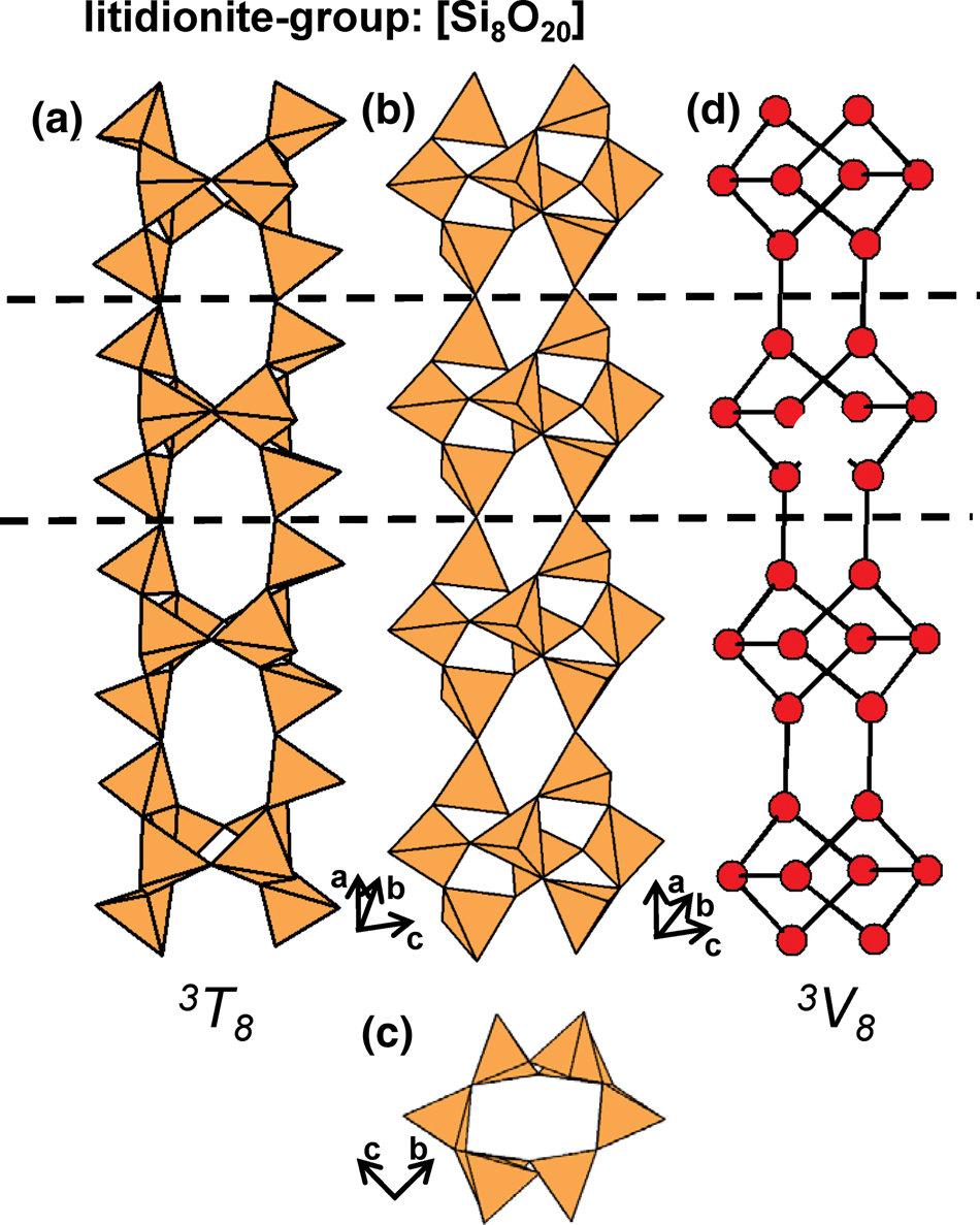
Members of the litidionite group include manaksite, fenaksite and calcinaksite, and there are isostructural synthetic structures such as K2Ca[Si4O10] (Schmidmair et al., Reference Schmidmair, Kahlenberg and Grießer2018), KNaM[Si4O10] (M = Cu2+, Mn2+ and Fe2+) (Brandão et al., Reference Brandão, Rocha, Reis, dos Santos and Jin2009) and Na2M[Si4O10] (M = Co2+, Ni2+, Cu2+ and Mn2+) (Kornev et al., Reference Kornev, Maksimov, Lider, Ilyukhin and Belov1972, Kawamura and Kawahara, Reference Kawamura and Kawahara1977, Durand et al., Reference Durand, Vilminot, Richard-Plouet, Derory, Lambour and Drillon1997, Cadoni and Ferraris, Reference Cadoni and Ferraris2011). Agrellite (Table 6) is not isostructural with the litidionite-group minerals but contains a tube that is topologically identical. In litidionite, 3T8 tubes link along the c-axis via ribbons of [5]Cu2+- and [7]Na+-polyhedra and [8]K+ ions occupy cavities within the tube (Figs 43a,b). In agrellite, tubes of tetrahedra extend along the c-axis and link along the b-axis via sheets of (CaO5F2)10−-polyhedra (Ca1 and Ca4) and (CaO5F)9−-octahedra (Ca2 and Ca3). The Ca1 site may be partly occupied by REEs and Sr2+, and cavities within the tube of tetrahedra are occupied by [8]Na+ ions (Figs 43c,d). In both structures, 3T8 tubes and ribbons of higher coordination polyhedra occur in layers that alternate along [001] in litidionite-group minerals and along [010] in agrellite. Fenaksite and manaksite are the Fe2+- and Mn2+-analogues of litidionite, and calcinaksite is the Ca2+-analogue of litidionite that also contains (H2O).
The structure of litidionite viewed (a) orthogonal to the a-axis and (b) along the a-axis. The structure of agrellite viewed (c) orthogonal to the c-axis and (d) along the c-axis. In (d), F1 and F2 anions are shown as green circles. Fine dashed black lines outline the unit cell.

The tube in narsarsukite extends along the c-axis and consists of four-membered rings of corner-sharing tetrahedra that link to adjacent tetrahedra, along [001], through two tetrahedra of each ring (Figs 44a–c). Topologically, this 3V8 tube (Fig. 44d) is similar to the tube in litidionite but not identical (Fig. 42d). This tube extends parallel to chains of corner-sharing (TiO5(O,OH,F)-octahedra that extend along the c-axis and each link to four 3T8 tubes to form an open framework; channels in this framework are occupied by [7]Na+ ions (Figs 45a,b). Schingaro et al. (Reference Schingaro, Mesto, Lacalamita, Scordari, Kaneva and Vladykin2017) report the partial substitution Ti4+ + O2− ↔ Fe3+ + F−, (OH)− at octahedrally coordinated sites. There are various synthetic compounds with 3T8 ribbons and tubes: K2Sc[Si4O10]F (Kolitsch and Tillmanns, Reference Kolitsch and Tillmanns2004), Pb6O[Si6Al2]O20 (Siidra et al., Reference Siidra, Krivovichev and Depmeier2009) and K2In[Si4O10](OH) (Hung et al., Reference Hung, Wang, Kao and Lii2003) (Table 6).
(a, b, c) Tetrahedral representation of the 3T8 tube in narsarsukite projected (a) orthogonal to the c-axis, (b) onto (010), (c) along the c-axis and (d) a ball-and-stick (graphical) representation of the tube. Dashed black lines outline the geometrical and topological repeat unit of the tube.
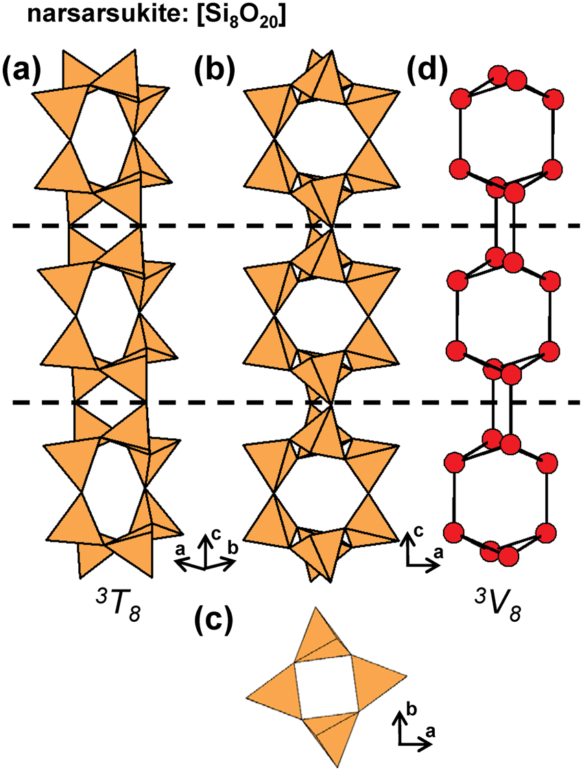
The structure of narsarsukite projected (a) onto (010) and (b) along the c-axis. Fine dashed black lines outline the unit cell and H atoms associated with (OH)– groups have been omitted for clarity

3T12 ribbons and tubes
In tuhualite, 3T12 ribbons extends along the c-axis and are modulated along the b-axis (Figs 46a–d). This 3V2 ribbon (Fig. 46e) is topologically identical to the ribbons in paravinogradovite, vinogradovite, bigcreekite, (Fig. 35d) the epididymite-group minerals (Fig. 38d) and caysichite-(Y) (Fig. 40d). Tuhualite contains three octahedrally coordinated sites occupied by Fe2+, Fe3+ (Fe1 and Fe2) and Na+ (Na1); these octahedra polymerise to form sheets that link to 3T12 ribbons. This linkage forms channels that extend along the a-axis and are occupied by octahedrally coordinated Na+ and (H2O) groups with subordinate K+ (Fig. 47a). Sheets of octahedra and 3T12 ribbons occur in layers that alternate along the a-axis (Fig. 47b). In zektzerite and emeleusite, the Li+-analogues of tuhualite, 3T12 ribbons link to sheets of Fe3+-octahedra (Zr4+-octahedra in zektzerite), Na+-polyhedra and Li+-tetrahedra. In both minerals, adjacent chains are linked to each other by Li+-tetrahedra, forming a framework rather than a ribbon of tetrahedra. However, both minerals are included in Table 6 as they belong to the tuhualite group.
(a, b, c) Tetrahedral representation of the 3T12 ribbon in tuhualite projected (a) onto (010), (b) orthogonal to the c-axis, (c) along the c-axis, (d) a ball-and-stick and (e) a graphical representation of the ribbon. Dashed black lines outline the geometrical and topological repeat unit of the ribbon.

The structure of tuhualite projected (a) onto (100) and (b) along the c-axis. Fine dashed black lines outline the unit cell and H atoms associated with (H2O) groups have been omitted for clarity.

The 3T12 [Si12O30]12− tubes in canasite and fluorcanasite extend along [010] and consist of two linked ribbons of six-membered rings (Figs 48a,b) that form a tube (Fig. 48c). Topologically, this 3V12 tube (Fig. 48d) is similar to the [Si12O30]12− tube in charoite (see below). In both minerals, 3T12 tubes link to corrugated sheets of Ca2+- and Na+-octahedra that are parallel to (100). Channels within each 3T12 tube are occupied by K+ ions (K1–K4) and by an additional (H2O) group in fluorcanasite. In canasite, there are four (OH)− sites whereas in fluorcanasite, there are two F sites (F2 and F3), an (OH) site and a split site that typically contains F > (OH) (F1), all of which bond to Na+- and Ca2+-octahedra. In fluorcanasite, 3T12 tubes and sheets of (CaO4(OH)F)8−-octahedra (Ca1–Ca3) and (NaO4F2)9−-octahedra (Na1–Na3) occur in layers that alternate along the c-axis (Figs 49a,b). Frankamenite is the triclinic polymorph of fluorcanasite. In miserite, 3T12 tubes extend along [001] and link to a more complicated slab that occurs in layers parallel (100). These slabs are composed of (CaO7–xFx)- and (CaO6–xFx)-polyhedra (where x = 1–2) and [Si2O7]6− dimers. Cavities are occupied by K+ ions (K1–K2) and (H2O) groups (Figs 49c,d).
(a, b, c) Tetrahedral representation of the 3T12 tube in canasite projected (a) onto (100), (b) orthogonal to the b-axis, (c) along the b-axis and (d) a ball-and-stick (graphical) representation of the tube. Dashed black lines outline the geometrical and topological repeat unit of the tube.

The structure of fluorcanasite projected (a) onto (001) and (b) along the b-axis. The structure of miserite projected (c) onto (010) and (d) along the c-axis. In both structures, (OH)– and (H2O) groups are shown as red circles and F anions are shown as green circles. Fine dashed black lines outline the unit cell.

Other 3Tn tubes
There are several synthetic compounds that contain 3T16 tubes and ribbons that are topologically distinct, with the vertex connectivity 3T8 or 3T16. Figures 50a–d show the 3T16 ribbon in synthetic Cs4Y2[Si8O20]F4 that consists of four- and eight-membered rings of Si4+-tetrahedra that link along [010]; this ribbon has a vertex degree 3V8 (Fig. 50e). Although this ribbon somewhat resembles that of a tube (Fig. 50c), it does not form a contiguous hollow cylinder (Figs 50b,d) and is therefore a ribbon. One can also more rigorously differentiate ribbons and tubes on the basis of topology. All ribbon-graphs can be represented in 2-dimensions in which no edges cross and no vertices overlap (Fig. 50e); this is not possible for tube-graphs. This distinction represents an important topological divide in 1-dimensional graphs and will be discussed in detail in a subsequent paper. In synthetic Cs4Y2[Si8O20]F4, 3T16 ribbons link to each other via chains of (YO4F2)7−-octahedra to form an open framework in which cavities are occupied by Cs+ ions (Schäfer and Schleid, Reference Schäfer and Schleid2007). Synthetic K4In2[Si8O20](OH)2 contains 3T16 tubes that consist of four-, six- and eight-membered rings of Si4+-tetrahedra that link along [010] (Figs 51a,b); this tube has a vertex degree 3V16 (Fig. 51c). The structure of synthetic K4In2[Si8O20](OH)2 is similar to that of synthetic Cs4Y2[Si8O20]F4 where (YO4F2)7−-octahedra are replaced by (InO4(OH)2)7−-octahedra and Cs+ is replaced by K+ (Hung et al., Reference Hung, Wang, Kao and Lii2003). The other synthetic compounds isostructural with K4In2[Si8O20](OH)2 are K4Lu2[Si8O20](OH)2 and Ru4Lu2[Si8O20]F2 (Kahlenberg and Manninger, Reference Kahlenberg and Manninger2014).
(a, b, c) Tetrahedral representation of the 3T16 ribbon in synthetic Cs4Y2[Si8O20]F4 projected (a) orthogonal to the b-axis, (b) onto (001), (c) along the b-axis, (d) a ball-and-stick and (e) a graphical representation of the ribbon. Dashed black lines outline the geometrical and topological repeat unit of the ribbon.

(a, b, c) Tetrahedral representation of the 3T16 tube in synthetic K4In2[Si8O20](OH)4 projected (a) orthogonal to the b-axis, (b) along the b-axis and (c) a ball-and-stick (graphical) representation of the tube. Dashed black lines outline the geometrical and topological repeat unit of the tube-ribbon.

Charoite has several polytypes; for simplicity we briefly describe only one: charoite-96; for more detailed descriptions, see Rozhdestvenskaya et al. (Reference Rozhdestvenskaya, Mugnaioli, Czank, Depmeier, Kolb, Reinholdt and Weirich2010, Reference Rozhdestvenskaya, Mugnaioli, Czank, Depmeier, Kolb and Merlino2011). Charoite contains a 3T17 tube (Figs 52a–c), a 3T12 tube (Figs 52d–f) and a 2T43T2 ribbon (Figs 52g–i), all of which extend along [001]. Each tube and ribbon links to an open framework of (NaO5(OH))10−- and Ca2+-octahedra. Charoite contains eleven sites occupied by alkali-metal and alkaline-earth-metal ions: K1–K7 (K7 is mostly vacant), Sr1 ions and W1–W3 groups occupy cavities within the 3T17 and 3T12 tubes and within the framework of octahedra (Fig. 53). The (OH)− groups are assumed to form (Si(O,OH)4), acid silicate groups and link to Na+ ions to form (NaO5OH)10−-octahedra. Denisovite has a similar structure but contains only 3T12 and 2T43T2 ribbons that extend along [001] and link to an open framework of Ca2+- and Na+-octahedra that are coordinated predominately by O2− and subordinate F− and (OH)−. In denisovite, cavities within the 3T12 tubes and within the framework of octahedra are occupied by K+ ions and (H2O) groups.
(a, b, c) Tetrahedral representation of the 3T17 tube in charoite projected (a) onto (100), (b) along the c-axis and (c) a ball-and-stick representation of this tube. (d, e, f) the 3T12 tube in charoite projected (d) orthogonal to the c-axis, (e) along the c-axis and (f) a ball-and-stick representation of this tube. (g, h, i) the 2T43T2 ribbon in charoite projected (g) onto (100), (h) along the c-axis and (i) a ball-and-stick representation of this ribbon. Dashed black lines outline the geometrical and topological repeat unit of the tube or ribbon.

The structure of charoite projected onto (001). Fine dashed black lines outline the unit cell and H atoms associated with (H2O) and (OH)− groups have been omitted for clarity.
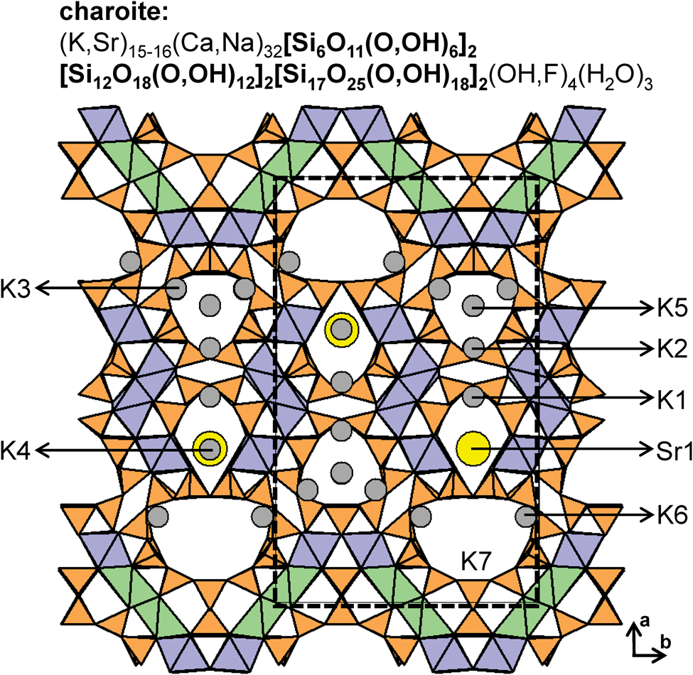
Synthetic Na16[Si32O64(OH)16] contains 3T32 ribbons that are topologically identical to the other 3Tn, 3V2 ribbons described above. These 3T32 ribbons consist of four-membered rings of Si4+- and (SiO3(OH))3−-tetrahedra that link along [102] to form planar ribbons. The 3T32 ribbons occur in layers perpendicular to (010) and link to sheets of Na+-polyhedra that are also perpendicular to (010) (Sassi et al., Reference Sassi, Gramlich, Miéhé-Brendié, Josien, Paillaud, Benggedach and Patarin2003).
Ashcroftine-(Y) is the largest and most complicated inosilicate that is currently known. It contains 3T56 tubes that consist of complex cages of Si4+-tetrahedra that link to each other along [001] by four 3T1–3T1 linkages. Each cage consists of four-, seven- and eight-membered rings (Figs 54a–e). Due to the complicated nature of the ashcroftine-(Y) structure, we do not provide a total structure description or figure here and instead, refer readers to Moore et al. (Reference Moore, Sen Gupta, Schlemper and Merlino1987).
(a, b, c) Tetrahedral representation of the 3T56 tube in ashcroftine projected (a) onto (010), (b) orthogonal to the c-axis, (c) along the c-axis, and (d, e) a ball-and-stick (graphical) representation of the tube. Dashed black lines outline the geometrical and topological repeat unit of the tube.
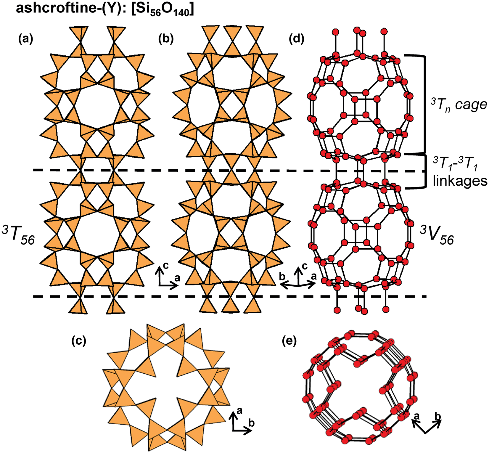
1Tr3Tr class
1T23T2 chains
The astrophyllite supergroup includes minerals from the astrophyllite, kupletskite and devitoite groups (Table 7) (Sokolova et al., Reference Sokolova, Cámara, Hawthorne and Ciriotti2017a), all of which contain 1T23T2 [Si4O12]8− chains that consist of a 2T2 chain in which each tetrahedron is decorated by a 1-connected tetrahedron (Figs 55a–d). The geometrical repeat unit contains four tetrahedra whereas the topological repeat unit contains only two vertices (1V13V1) (Fig. 55e). The 1T 23T 2 chains extend along the a-axis and link to adjacent chains along the b-axis via octahedrally or [5]-coordinated Ti4+, Nb5+ or Fe3+ (plus minor other ions) occupying the D site to form the H-sheet (Fig. 56a). There are four octahedrally coordinated M-sites (M1–M4) that are occupied dominantly by Fe2+ (astrophyllite group) and Mn2+ (kupletskite group) although minor amounts of other cations (e.g. Zn2+; Piilonen et al., Reference Piilonen, LaLonde, McDonald, Gault and Larsen2003a,Reference Piilonen, McDonald and LaLondeb, Reference Piilonen, Pekov, Back, Steede and Gault2006) can be incorporated. The resulting octahedra share edges to form a continuous sheet, called the O-sheet (Fig. 56b). The O-sheet is enclosed between two H-sheets to form an HOH block (Fig. 56c) (Sokolova, Reference Sokolova2012; Sokolova et al., Reference Sokolova, Cámara, Hawthorne and Ciriotti2017a), similar to the HOH block in TS-block minerals (Sokolova, Reference Sokolova2006; Sokolova and Cámara, Reference Sokolova and Cámara2017). Species that occur between adjacent TS-blocks form the I-block. Astrophyllite-supergroup minerals that contain HOH blocks that link to one another directly (along the c-axis) through common vertices of the D-polyhedron are designated as Type-1 structures and include the astrophyllite- and kupletskite-group minerals. Astrophyllite-supergroup minerals that contain HOH blocks that do not link directly are designated as type-2 structures and are members of the devitoite group (Table 7).
(a, b, c) Tetrahedral representations of the 1T23T2 chain in astrophyllite projected (a) onto (010), (b) orthogonal to the a-axis, (c) along the a-axis, (d) a ball-and-stick and (e) a graphical representation of the chain. Dashed black lines outline the geometrical and topological repeat unit of the chain.

The structure of astrophyllite highlighting the (a) H-sheet (and I-block cations) and (b) O-sheet projected orthogonal to the a-axis and (c) the HOH-block and I-block viewed along the a-axis. The A and B, I-block cations are labelled, and the H atoms associated with (OH)− groups are shown as red circles. Fine dashed black lines outline the unit cell.
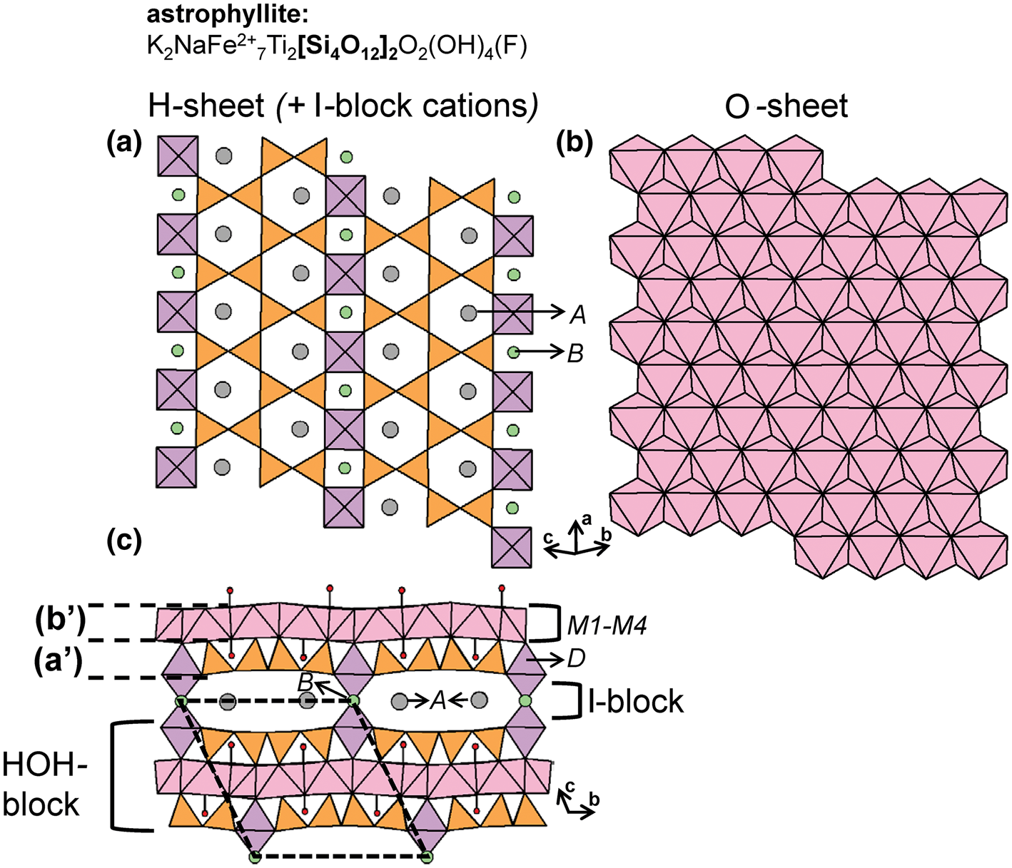
Minerals with 1Tr3Tr and 2T23Tr ribbons.

References: (1) Cámara et al. (Reference Cámara, Sokolova, Abdu and Hawthorne2010), Zhitova et al. (Reference Zhitova, Krivovichev, Hawthorne, Krzhizhanovskaya, Zolotarev, Abdu, Yakovenchuk, Pakhomovsky and Goncharov2017), Woodrow (Reference Woodrow1967), Shi et al. (Reference Shi, Ma, Li, Yamnova and Pushcharovskii1998), Piilonen et al. (Reference Piilonen, McDonald and LaLonde2003b); (2) Agakhanov et al. (Reference Agakhanov, Pautov, Sokolova, Abdu and Karpenko2016); (3) Uvarova et al. (Reference Uvarova, Sokolova, Hawthorne, Agakhanov and Pautov2008), Agakhanov et al. (Reference Agakhanov, Pautov, Uvarova, Sokolova, Hawthorne and Karpenko2008, Reference Agakhanov, Pautov, Sokolova, Abdu and Karpenko2016); (4) Nickel et al. (Reference Nickel, Rowland and Charette1964), Cámara et al. (Reference Cámara, Sokolova, Abdu and Hawthorne2010); (5) Stepanov et al. (Reference Stepanov, Bekenova, Levin, Sokolova, Hawthorne and Dobrovol'skaya2012); (6) Kapustin (Reference Kapustin1973), Sokolova and Hawthorne (Reference Sokolova and Hawthorne2016), Sokolova et al. (Reference Sokolova, Cámara, Hawthorne and Ciriotti2018a); (7) Christiansen et al. (Reference Christiansen, Johnsen and Stahl1998), Piilonen et al. (Reference Piilonen, McDonald and Lalonde2001, Reference Piilonen, Pekov, Back, Steede and Gault2006); (8) Cámara et al. (Reference Cámara, Sokolova, Abdu and Hawthorne2010); (9) Cámara et al. (Reference Cámara, Sokolova, Abdu and Hawthorne2010), Piilonen et al. (Reference Piilonen, Lalonde, Mcdonald and Gault2000); (10) Sokolova et al. (Reference Sokolova, Day, Hawthorne, Kasatkin, Downs, Horváth and Pfenninger-Horváth2019); (11) Kampf et al. (Reference Kampf, Rossman, Steele, Pluth, Dunning and Walstrom2010); (12) Sokolova et al. (Reference Sokolova, Cámara, Hawthorne, Semenov and Ciriotti2017b), Sokolova and Cámara (Reference Sokolova and Cámara2008), Shi et al. (Reference Shi, Ma, Li, Yamnova and Pushcharovskii1998); (13) Khomyakov et al. (Reference Khomyakov, Cámara, Sokolova, Abdu and Hawthorne2011); (14) Sokolova et al. (Reference Sokolova, Day, Hawthorne and Kristiansen2018b); (15) Cámara et al. (Reference Cámara, Sokolova, Abdu and Hawthorne2014), Ferraris et al. (Reference Ferraris, Ivaldi, Khomyakov, Sobolova, Belluso and Pavese1996); (16) Cámara et al. (Reference Cámara, Sokolova, Hawthorne, Rowe, Grice and Tait2013); (17) Oberti et al. (Reference Oberti, Hawthorne, Ungaretti and Cannillo1993); (18) Evans and Mrose (Reference Evans and Mrose1966), Evans and Mrose (Reference Evans and Mrose1977); (19) Yang et al. (Reference Yang, Downs, Evans and Pinch2014), Kolitsch et al. (Reference Kolitsch, Merlino, Belmonte, Carbone, Cabella, Lucchetti and Ciriotti2018); (20) Czank and Bissert (Reference Czank and Bissert1993); (21) Bakakin and Soloveva (Reference Bakakin and Soloveva1970); (22) Veblen and Burnham (Reference Veblen and Burnham1978b); (23) Konishi et al. (Reference Konishi, Akai and Kurokawa1993); (24) Tateyama et al. (Reference Tateyama, Shimoda and Sudo1978), Ams et al. (Reference Ams, Jenkins, Boerio-Goates, Morcos, Navrotsky and Bozhilov2009); (25) Hesse and Liebau (Reference Hesse and Liebau1980), Filipenko et al. (Reference Filipenko, Pobedimskaya, Ponomarev and Belov1971); (26) Merlino (Reference Merlino1983); (27) Downs et al. (Reference Downs, Pinch, Thompson, Evans and Megaw2016); (28) Rastsvetaeva and Aksenov (Reference Rastsvetaeva and Aksenov2011); (29) Hesse and Liebau (Reference Hesse and Liebau1980), Wang et al. (Reference Wang, Xu, Zhou, Yu and Qiu2015); (30) Hesse and Liebau (Reference Hesse and Liebau1980).
* Indicates the cTr expression of an additional structural unit including a chain, ribbon, tube, cluster or sheet of [TO4]n– tetrahedra in the respective mineral.
In astrophyllite-group minerals, the A and B sites are occupied by K+ and Na+, respectively (Figs 56a), except in nalivkinite and bulgakite (in which the A site is occupied by Li+ with associated (H2O) to complete its coordination), and in tarbagatite and bulgakite (in which the B site may contain dominant Ca2+). In kupletskite-group minerals, the A and B sites are occupied by K+ and Na+, respectively, except in kupletskite-(Cs) in which the A site is occupied by Cs+. Laverovite is a kupletskite-group mineral but differs from the others in having Zr4+ occupying the D site. The devitoite-group minerals have much more diverse I-blocks, in accord with the absence of direct linkage between adjacent HOH blocks, and also more ordered O-sheets. Thus, lobanovite has (most importantly) Na+ at the M1 site and Mg2+ at the M4 site. Sveinbergeite has (H2O) at the A site, Ca2+ at the B site, and 1 apfu Fe3+ at the M sites. Devitoite (Figs 57a,b) has Ba2+ at both the A and B sites, [5]-coordinated Fe3+ at the D site, and (PO4)3−2 and (CO3)2− groups in the I-block; in heyerdahlite, Mn2+ occupies the M sites.
The structure of devitoite highlighting the (a) H- and O-sheet projected onto (001) and the (b) HOH-block and I-block viewed along the a-axis. In (b), the C and O atoms of the (CO3) groups are shown as dark grey and red circles, respectively. The I-block, [PO4] groups are shown as yellow polyhedra and [5]Fe3+-polyhedra are shown in dark pink to differentiate them from Fe2+-octahedra. Fine dashed black lines outline the unit cell and H atoms associated with (OH)– groups are omitted for clarity.
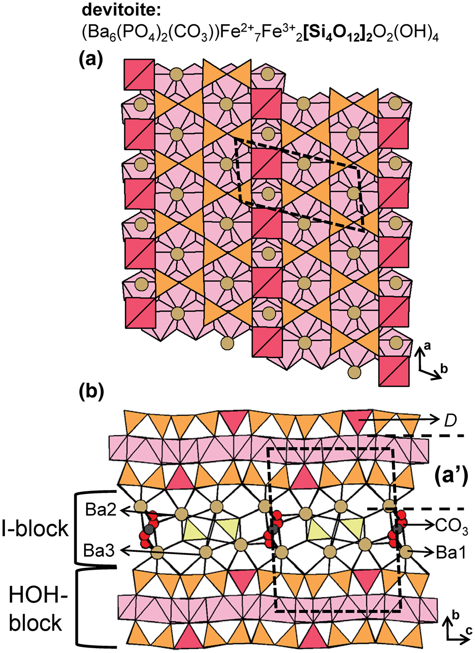
1T23T4 ribbons
The 1T23T4 [Si6O17]10− ribbon in nafertisite consists of ribbons of edge-sharing hexagons, where each six-membered ring is decorated by two 1-connected tetrahedra (Figs 58a–e). The 1T23T4 ribbons extends along [100] and are linked along [001] to sheets of (Fe2+O4(OH)2)8−-octahedra (M1–M3) that are parallel to the a–b plane (110) (O-sheet) (Fig. 59a). Here, 1T23T4 ribbons occur in layers parallel to (110) and are linked to adjacent ribbons along [010] via (ZrO5F)7−-octahedra (D site), forming the H-sheet. The linkage of O- and H-sheets forms HOH blocks that are linked to adjacent blocks along [001] through common F− anions of the D-site octahedra. Similar structure modules occur in astrophyllite-supergroup minerals (Sokolova et al., Reference Sokolova, Cámara, Hawthorne and Ciriotti2017a) and TS-block minerals (Sokolova, Reference Sokolova2006). In nafertisite, HOH blocks are separated by the A, W1, B and C sites that form the I-block (Fig. 59b). The A site is split into two disordered sites, A1 and A2, where K+ at A1 forms partly occupied (KO8F)16−-polyhedra, and Na+ at A2 forms (NaO4(H2O)F)8−-octahedra. Due to the short distance between the A1 and W1 sites, they cannot both be locally occupied. Na+ fully occupies the B site forming (NaO8F2)17−-polyhedra and the C site is occupied by Na+ with minor Rb+ and Cs+. Nafertisite contains two (OH)− groups that are associated with the M1–M3 octahedra of the O-sheet.
(a, b, c) Tetrahedral representations of the 1T23T4 ribbon in nafertisite projected (a) onto (010), (b) onto (001), (c) along the a-axis, (d) a ball-and-stick and (e) a graphical representation of the ribbon. Dashed black lines outline the geometrical and topological repeat unit of the ribbon.

The structure of nafertisite highlighting the (a) H- and O-sheets projected onto (001) and the (b) HOH-block and I-block viewed along the a-axis. The H atoms associated with (OH)− groups linked to octahedra of the O-sheet are shown as small red circles, (H2O) groups (W1) are shown as larger red circles and I-block cations are shown as green circles. Fine dashed black lines outline the unit cell which is halved along the c- and b-axes in (b).

1T23T6 ribbons
The 1T23T6 [Si8O22]12− ribbon in veblenite consists of ribbons of edge-sharing hexagons of tetrahedra decorated by single, 1-connected tetrahedra along its periphery (Figs 60a–d). The ribbons link through dominantly Nb5+-octahedra (D site) to form a discontinuous H-sheet, and adjacent D-octahedra are linked along [010] by [Si2O7]6− dimers. The (Fe2+/3+(O,OH)6)- and (Mn2+(O,OH)6)-octahedra share common edges to form a modulated O-sheet parallel to (001) (Fig. 61a). The H- and O-sheets link to form an HOH block (cf. astrophyllite-supergroup minerals, (Fig. 56). The HOH blocks are linked along [001] by an I-block that contains the A1 and A2 sites occupied by K+, the B site which is dominantly vacant (with minor Na+), and (H2O) which occupies five sites (W1–W5) (Fig. 61b).
(a, b) Tetrahedral representations of the 1T23T6 ribbon in veblenite projected (a) orthogonal to the a-axis, (b) along the a-axis, (c) a ball-and-stick and (d) a graphical representation of the ribbon. Dashed black lines outline the geometrical and topological repeat unit of the ribbon.
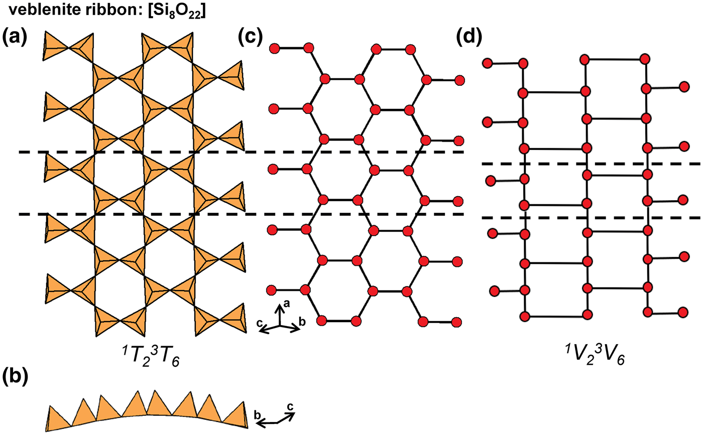
The structure of veblenite highlighting the (a) H- and O-sheet projected onto (001) and the (b) HOH-block and I-block viewed along the a-axis. Here, I-block, (H2O) groups are shown as red circles. Fine dashed black lines outline the unit cell and H atoms associated with (OH)− groups are omitted for clarity.
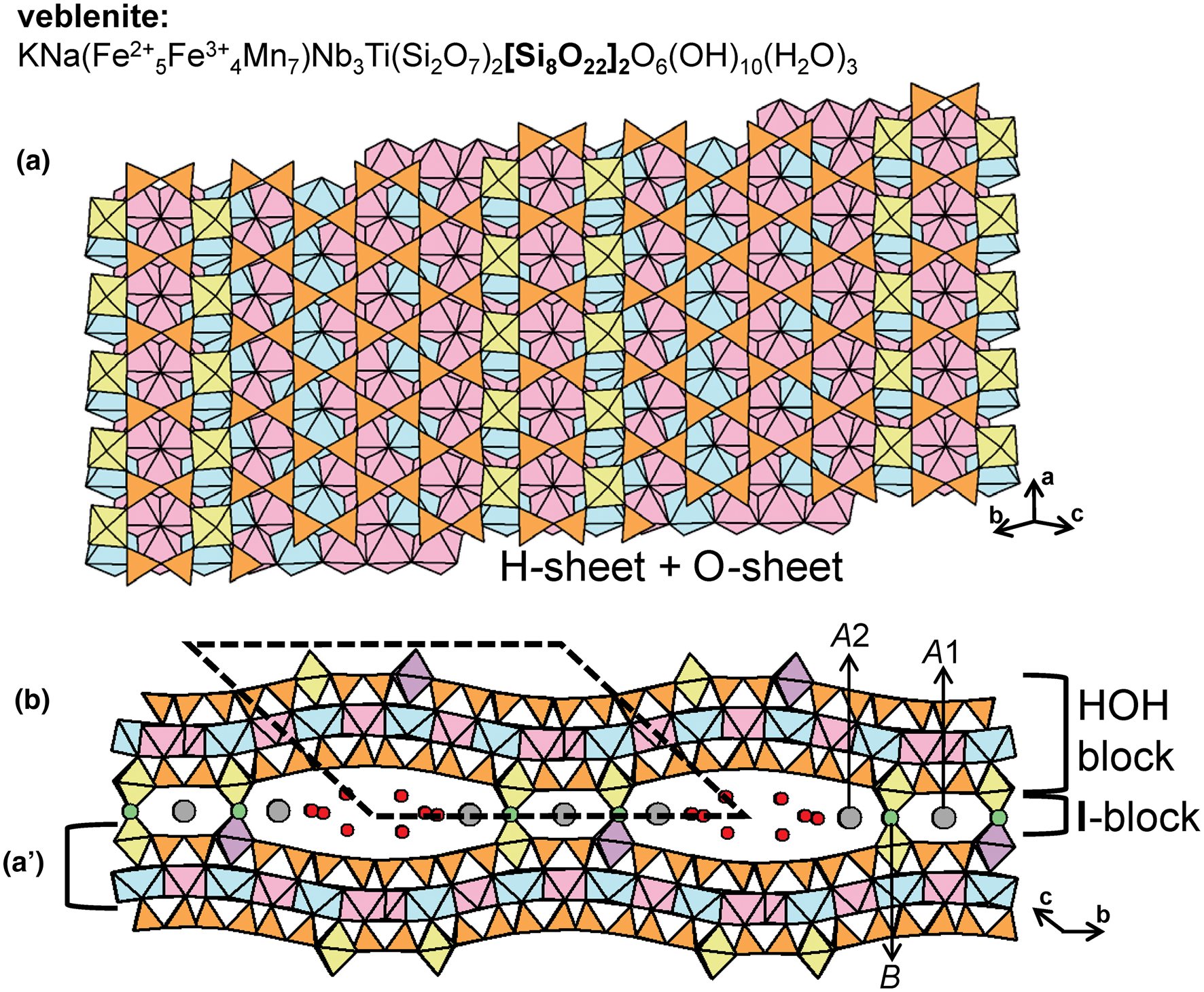
2Tr3Tr class
2T23T2 chains and ribbons
The general formula of the amphibole-supergroup minerals is AB2C5T8O22W2 where A = □, Na+, K+ and Ca2+; B = Na+, Li+, Ca2+, Mn2+, Fe2+ and Mg2+; C = Mg2+, Fe2+, Mn2+, Al3+, Fe3+, Mn3+, Ti4+ and Li+; T = Si4+, Al3+ and Ti4+; W = (OH)−, F−, Cl− and O2− (Hawthorne Reference Hawthorne, Veblen and Ribbe1981, Reference Hawthorne1983b,Reference Hawthornec; Hawthorne and Oberti, Reference Hawthorne, Oberti, Hawthorne, Oberti, Della Ventura and Mottana2007; Hawthorne et al., Reference Hawthorne, Oberti, Harlow, Maresch, Martin, Schumacher and Welch2012). The 2T23T2 ribbon in the amphibole-supergroup minerals has a geometrical repeat unit that contains four tetrahedra and consists of edge-sharing hexagons of tetrahedra that extend in the c-direction (Figs 62a–d). There is a strip of edge-sharing octahedra (M1–M3), occupied by the C-group cations, that links to 2T23T2 ribbons in the a- and b-directions (Fig. 63a). The M4 site is situated at the periphery of the strip of octahedra and is occupied by B-group cations; it is surrounded by eight oxygen atoms not all of which necessarily bond to the central cation. The A site occurs at the centre of a large cavity between the back-to-back 2T23T2 ribbons (Fig. 63b), but the A-group cations actually occupy the off-centered sites A(2) and A(m). There are (currently) six known structural variants of the amphibole arrangement. We may divide these structures into two types: (1) those that involve different stacking sequences in the a-direction (C2/m, Pnma and Pnmn), and (2) those that are derivatives of (1) and involve differences in coordination (P21/m) and/or topochemistry (P2/a or C1) (Hawthorne and Oberti, Reference Hawthorne, Oberti, Hawthorne, Oberti, Della Ventura and Mottana2007). Complete details of the amphibole structure and chemistry are given in Hawthorne et al. (Reference Hawthorne, Oberti, Della Ventura and Mottana2007) and Oberti et al. (Reference Oberti, Hawthorne, Cannillo, Cámara, Hawthorne, Oberti, Della Ventura and Mottana2007), and Hawthorne (Reference Hawthorne2012b) has related the bond topologies and chemical compositions of the T–O–T (pyroxene, amphibole, pyribole and mica supergroups) and HOH (astrophyllite, nafertisite, veblenite and mica supergroups) minerals via (algebraic) generating functions.
(a, b) Tetrahedral representations of the 2T23T2 ribbon in amphibole-supergroup minerals projected (a) orthogonal to the c-axis, (b) onto (100), (c) a ball-and-stick and (d) a graphical representation of the ribbon. Dashed black lines outline the geometrical and topological repeat unit of the ribbon.
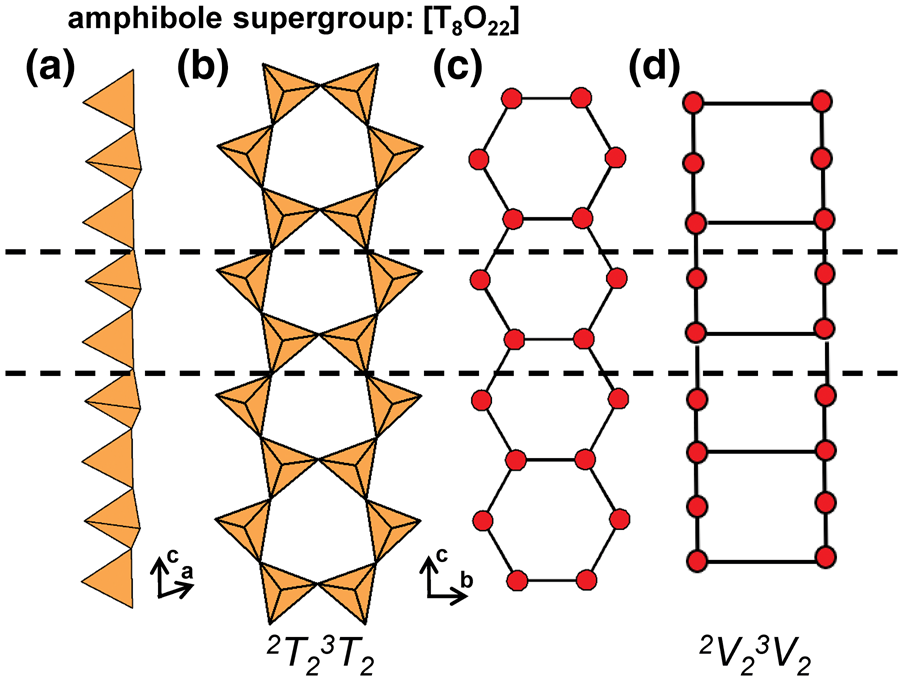
The structure of richterite projected (a) onto (100) and (b) along the c-axis (a). The structure of plancheite projected (c) onto (100) and (d) along the c-axis. Fine dashed black lines outline the unit cell and H atoms associated with (OH)− groups are omitted for clarity
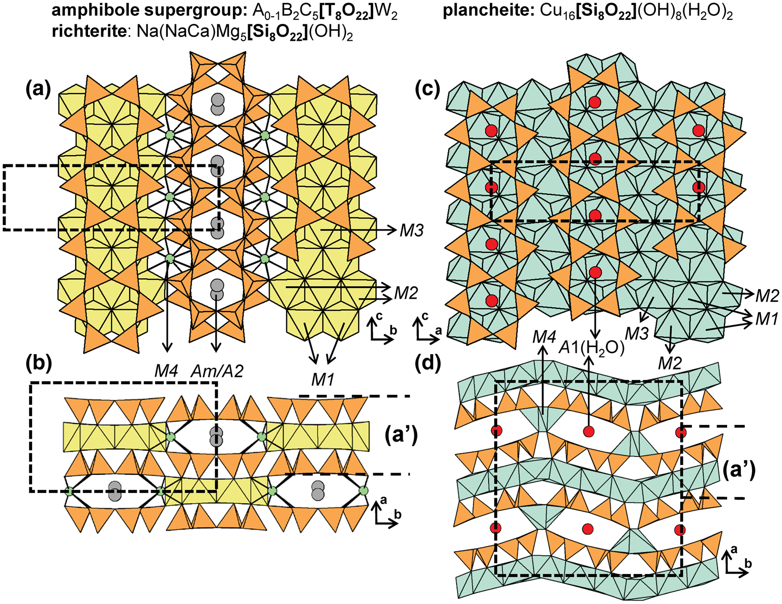
Lavinskyite-2O (1M) and plancheite both contain 2T23T2 ribbons that link to both sides of a continuous sheet of (Cu(O,OH)6)-octahedra (M1–M3), forming a T–O–T block. In lavinskyite, these blocks are linked to each other by K+ ions (A site) that occupy cavities between back-to-back 2T23T2 ribbons. T–O–T blocks are also linked by [5]Cu2+- and Li+-polyhedra (M4 site). Plancheite is isostructural with lavinskyite-2O where 2T23T2 ribbons link to sheets of (CuO4(OH)2)8−-octahedra (Fig. 63c), (H2O) groups replace K+ at the A site, and [5]Cu2+ replaces Li+ at the M4 site (Fig. 63d). These minerals contain 2V23V2 ribbons that are topologically identical to the ribbons in amphibole-supergroup minerals. For a more detailed description of lavinskyite and plancheite see Evans and Mrose (Reference Evans and Mrose1966, Reference Evans and Mrose1977), Yang et al. (Reference Yang, Downs, Evans and Pinch2014) and Kolitsch et al. (Reference Kolitsch, Merlino, Belmonte, Carbone, Cabella, Lucchetti and Ciriotti2018).
The 2T23T2 chains in synthetic Li2Mg2[Si4O11] and Fe3[BeSi3O9(OH)]2 (Figs 64a–f) are topologically identical to the [Si8O22]12− chains in vlasovite (see below) and the [Si4O6(OH)5]1− chain in revdite (see below) but not with the 2V23V2 ribbon in amphibole-supergroup minerals (Fig. 62d). In synthetic Li2Mg2[Si4O11], T1–T4 are occupied by Si4+ (Figs 64a,b), and in synthetic Fe3[BeSi3O9(OH)]2,T1–T3 are occupied by Si4+ and T4 is occupied by Be2+ (Figs 64c,d). In synthetic Li2Mg2[Si4O11], 2T23T2 chains extend along the c-axis and link to ribbons of Mg2+-octahedra and Li+-polyhedra that also extend along the c-axis; chains and ribbons occur in layers that alternate along [110]. In synthetic Fe3[BeSi3O9(OH)]2, each 2T23T2 chain links to several ribbons of Fe2+-octahedra, both of which extend along the c-axis, and chains of tetrahedra and ribbons of octahedra occur in layers that alternate along the a-axis. For a more detailed total structure description, see Czank and Bissert (Reference Czank and Bissert1993) and Bakakin and Soloveva (Reference Bakakin and Soloveva1970).
Tetrahedral representations of the 2T23T2 chains in (a, b) synthetic Li2Mg2[Si4O11] and (c, d) Fe3[BeSi3O9OH]2 projected (a) orthogonal to the c-axis, (b) along the c-axis, (c) onto (100), (d) along the c-axis, (e) a ball-and-stick and (f) a graphical representation of the both chains. The T4 site in synthetic Fe3[BeSi3O9OH]2 is occupied by Be2+ and is shown as a dark green tetrahedron. Dashed black lines outline the geometrical and topological repeat unit of the chain.

2T23T4 ribbons
The 2T23T4 ribbon in jimthompsonite and clinojimthompsonite has a geometrical repeat unit that contains three distinct tetrahedra. Each ribbon is planar and consists of three polymerised 2T2 chains that form a ribbon that extends along the c-axis and consists of staggered edge-sharing hexagons (Figs 65a–c). The ribbon in clinojimthompsonite and jimthompsonite has the vertex degree 2V23V4 (Fig. 65d). The geometrical relations of the triple-chain in jimthompsonite and other biopyriboles such as amphiboles have been discussed in detail (e.g. Thompson, Reference Thompson1978; Papike and Ross, Reference Papike and Ross1970; Law and Whittaker, Reference Law and Whittaker1980; Veblen and Burnham, Reference Veblen and Burnham1978a,Reference Veblen and Burnhamb; Cameron and Papike, Reference Cameron and Papike1979; Chisholm, Reference Chisholm1981) and M-site substitutions and compositional limits are considered by Maresch et al. (Reference Maresch, Welch, Gottschalk, Ruthmann, Czank and Ashbrook2009) and Jenkins et al. (Reference Jenkins, Gilleaudeau, Kawa, Dibiase and Fokin2012). In clinojimthompsonite and jimthompsonite, the M1–M5 sites are occupied by Mg2+ (and subordinate Fe2+), these octahedra polymerise to form planar ribbons that extend along the c-axis. Mg2+ ions form (MgO4(OH)2)8−-octahedra at the M1–M3 sites and Mg2+-octahedra at the M4 and M5 sites. Each 2T23T4 ribbon links to three distinct ribbons of Mg2+-octahedra and links such ribbons to each other along the a- and b-axes (Figs 66a,b).
(a, b) Tetrahedral representations of the 2T23T4 ribbon in jimthompsonite projected (a) orthogonal to the c-axis, (b) onto (100), (c) a ball-and-stick and (d) a graphical representation of the ribbon. Dashed black lines outline the geometrical and topological repeat unit of the ribbon.

The structure of jimthompsonite projected (a) onto (100) and (b) along the c-axis. Fine dashed black lines outline the unit cell and H atoms associated with (OH)– groups are omitted for clarity.

Various synthetic compounds isostructural with clinojimthompsonite have also been reported: Na2Mg4[Si6O16](OH)2 and NaMg4[Si6O15(OH)](OH)2 in which Na+ occupies the A site (vacant in clinojimthompsonite and jimthompsonite) and the M5 site (Tateyama et al.,Reference Tateyama, Shimoda and Sudo1978; Ams et al., Reference Ams, Jenkins, Boerio-Goates, Morcos, Navrotsky and Bozhilov2009) (Table 7). This 2T23T4 ribbon also occurs in synthetic Ba4[Si6O16] and links to sheets of Ba2+-polyhedra.
The 2T23T4 [Si6O16]8− ribbons in okenite and yangite have a geometrical repeat unit that contain three distinct tetrahedra that polymerise to form planar ribbons of alternating four- and six-membered rings that extend along the b-axis (Figs 67a–c). Geometrically, this ribbon is related to ribbons in tobermorite-11Å (see below), epididymite-group minerals (Figs 38a–c) and related synthetic compounds such as β-Na3Y[Si6O15] (Haile and Wuensch, Reference Haile and Wuensch1997) as they all contain ribbons of two 2T3 (wollastonite-like) chains with varying degrees of polymerisation between the tetrahedra of each chain. Topologically, this 2V23V4 ribbon is similar to the 2V23V2 ribbon in amphibole-supergroup minerals (Fig. 62d) but is not identical (Fig. 67d).
(a, b) Tetrahedral representations of the 2T23T4 ribbon in okenite projected (a) onto (100), (b) onto (001), (c) a ball-and-stick and (d) a graphical representation of the ribbon. Dashed black lines outline the geometrical and topological repeat unit of the ribbon.

In addition to ribbons, okenite also contains planar [Si6O15]6− sheets that consist of five- and eight-membered rings of tetrahedra and correspond to a (52.8)2(5.82)1 net (Hawthorne et al., Reference Hawthorne, Uvarova and Sokolova2019). Okenite contains six Ca sites (Ca1–Ca6), four of which are occupied by Ca2+ (Ca1–Ca4) that form planar ribbons of edge-sharing octahedra that extend along the b-axis and are linked to each other along the a-axis by 2T23T4 chains (Fig. 68a). A complicated [Ca2(H2O)12]4+ layer involving (CaO2(H2O)6)2−- (Ca5) and (CaO2(H2O)5)2−-polyhedra (Ca6) links adjacent sheets of tetrahedra along the c-axis. The stacking sequence, involving ribbons and sheets of tetrahedra, ribbons of Ca2+-octahedra and the [Ca2(H2O)12]4+ layer, is shown in Fig. 68b. The ribbon in yangite is topologically identical to that in okenite. However, the interstitial structure of yangite is relatively simple, containing one [5]- and one [6]-coordinated sites occupied by Pb2+ and Mn2+, respectively, that form ribbons of edge-sharing octahedra. These ribbons and 2T23T4 chains occur in layers that alternate along the c-axis (Fig. 68b).
The structure of okenite projected (a) onto (001) and (b) along the b-axis. Here, layers that contain [Si6O16]8− ribbons, [Si6O15]6− sheets and [Ca2(H2O)12]4+ dimers are labelled. Fine dashed black lines outline the unit cell and H atoms associated with (H2O) groups are omitted for clarity.

2T2 3T6 ribbons
Two topologically distinct variants of the 2T23T6 ribbon occur in synthetic K6Eu3+2[Si8O19(OH)2](OH)2(H2O)11 and Ba5[Si8O21]. The geometrical repeat unit of the 2T23T6 ribbon in the former contains three distinct tetrahedra that polymerise to form ribbons that extend along the c-axis (Figs 69a–d). These ribbons consist of two linked 2T23T2 chains similar to those in synthetic Li2Mg2[Si4O11] (Figs 64a,b) and vlasovite (see below). The 2T23T6 ribbons link to each other via (EuO4(OH)2)7−-octahedra, forming an open framework in which channels are occupied by [8–9]K+ ions and (H2O) groups. The 2T23T6 ribbon in synthetic Ba5[Si8O21] consists of two linked 2T23T2 amphibole-like ribbons (Figs 69e–h) and extends along the b-axis. These ribbons link to sheets of [8]Ba2+-polyhedra that are parallel to (010).
(a, b, c) Tetrahedral representations of the 2T23T6 ribbon in synthetic K6Eu3+2[Si8O19(OH)2](OH)2(H2O)9 projected (a) onto (010), (b) onto (100), (c) along the c-axis and (d) a ball-and-stick (graphical) representation of the ribbon. (e, f, g) Tetrahedral representations of the 2T23T6 ribbon in synthetic Ba5[Si8O21] projected (e) onto (100), (f) onto (001), (g) along the b-axis and (h) a ball-and-stick (graphical) representation of the ribbon. Dashed black lines outline the geometrical and topological repeat unit of the ribbon.
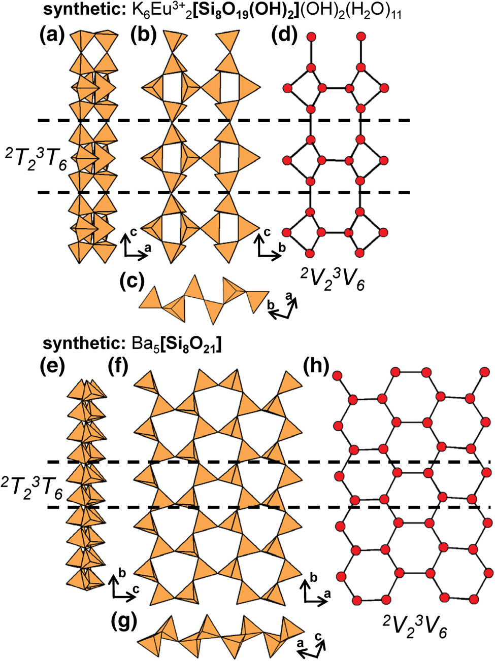
2T23T8 ribbons
The geometrical repeat unit of the ribbon in synthetic Ba6[Si10O26] contains ten distinct Si4+-tetrahedra that polymerise to form 2T23T8 ribbons that extend parallel to [010] (Figs 70a–d). The structure of synthetic Ba6[Si10O26] is closely related to those of synthetic Ba5[Si8O21] (Figs 69e–g) and Ba4[Si6O16] (Hesse and Liebau, Reference Hesse and Liebau1980) in which ribbons of tetrahedra link to sheets of [8]Ba2+-polyhedra that are parallel to (010).
(a, b, c) Tetrahedral representations of the 2T23T8 ribbon in synthetic Ba6[Si10O26] projected (a) onto (100), (b) onto (001), (c) along the b-axis and (d) a ball-and-stick (graphical) representation of the ribbon. Dashed black lines outline the geometrical and topological repeat unit of the ribbon.

2T33T4 ribbons
The 2T33T4 [Si7O18(OH)]9− ribbons in tokkoite, senkevichite and tinaksite (Table 8) have a geometrical repeat unit that contains seven distinct Si4+-tetrahedra where T7 is an acid silicate group: (SiO3OH)3−. Each 2T33T4 ribbon consists of alternating four- and eight-membered rings (Figs 71a–e) and in tokkoite, extend along [001] and link to sheets of Ca2+-octahedra (M1, M3–M4) and [7]Ca2+-polyhedra (M2) that extend parallel to the b–c plane (Figs 72a,b). These sheets are linked along [100] by 2T33T4 ribbons, forming large tunnels that are occupied by K+ ions (A1–A2) (Fig. 72c). In tinaksite and senkevichite, Ti4+ and [7]Na+ occupy the M1 and M2 sites, respectively, and Cs+ occupies the A1 site in senkevichite. The tokkoite → tinaksite (senkevichite) substitution: 2Ca2+(M1+M2) + (F,OH)− ↔ Ti4+(M1) + Na+(M2) + O− was suggested by Rozhdestvenskaya and Nikishova (Reference Rozhdestvenskaya and Nikishova2002).
(a, b, c) Tetrahedral representations of the 2T33T4 ribbon in tokkoite projected (a) onto (100), (b) orthogonal to the c-axis, (c) along the c-axis, (d) a ball-and-stick and (e) a graphical representation of the ribbon. Dashed black lines outline the geometrical and topological repeat unit of the ribbon.
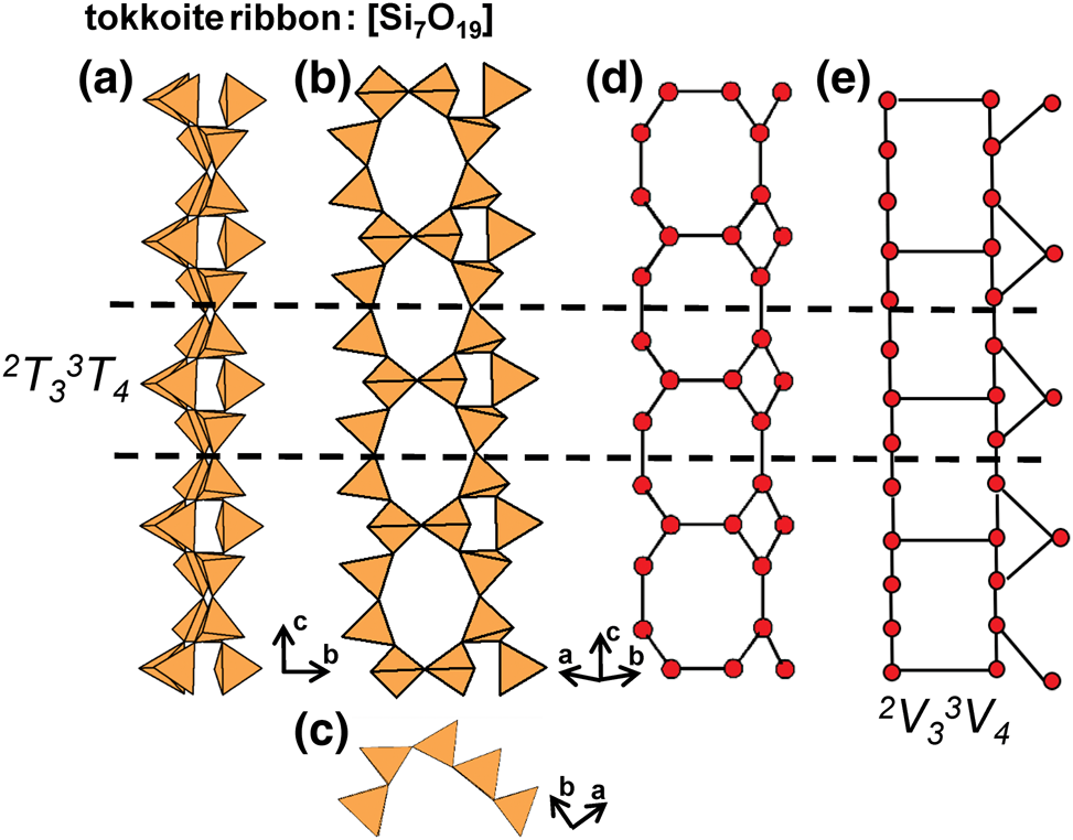
The structure of tokkoite projected (a) onto (010) showing the linkage of 2T33T4 ribbons to sheets of Ca2+-polyhedra, (b) sheets of Ca2+-polyhedra projected onto (100) and (c) the alternating layers of 2T 33T 4 ribbons and sheets of Ca2+-polyhedra projected along the c-axis. Fine dashed blacked lines outline the unit cell and H atoms associated with (OH)− groups are omitted for clarity
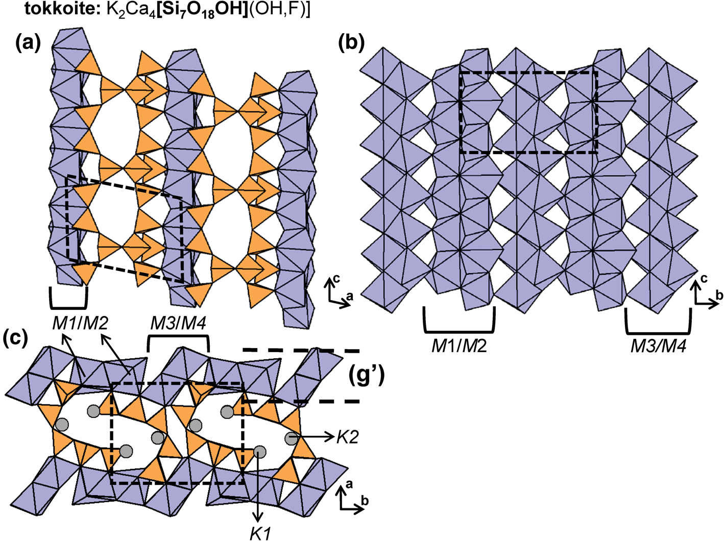
Minerals with 2Tr3Tr ribbons.
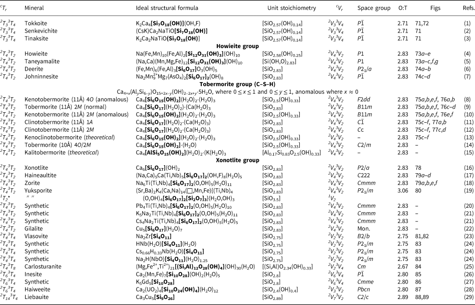
References: (1) Rozhdestvenskaya et al. (Reference Rozhdestvenskaya, Nikishova, Lazebnik and Lazebnik1989), Lacalamita et al. (Reference Lacalamita, Mesto, Kaneva, Scordari, Pedrazzi, Vladykin and Schingaro2017); (2) Agakhanov et al. (Reference Agakhanov, Pautov, Uvarova, Sokolova, Hawthorne and Karpenko2005), Uvarova et al. (Reference Uvarova, Sokolova, Hawthorne, Agakhanov, Pautov and Karpenko2006); (3) Rogov et al. (Reference Rogov, Rogova, Voronkov and Moleva1965), Bissert (Reference Bissert1980); (4) Wenk (Reference Wenk1974), Wenk (Reference Wenk1973), Ghent et al. (Reference Ghent, Stout and Erdmer1990); (5) Wenk (Reference Wenk1974), Matsubara (Reference Matsubara1981), Aoki (Reference Aoki, Akasako and Ishida1981); (6) Fleet (Reference Fleet1977), Agrell et al. (Reference Agrell, Brown and McKie1965), Wenk et al. Reference Wenk, Biagioni, Hsiao, Lee, Tanzella, Yeh, Hodgson and Nissen1976, Worthing (Reference Worthing1987); (7) Grice and Dunn (Reference Grice and Dunn1994), Dunn et al. (Reference Dunn, Peacor, Su, Nelen and von Knorring1986), Brugger and Berlepsch (Reference Brugger and Berlepsch1997); (8) Merlino et al. (Reference Merlino, Bonaccorsi and Armbruster2001); (9) Merlino et al. (Reference Merlino, Bonaccorsi and Armbruster2001), Hamid (Reference Hamid1981); (10) Merlino et al. (Reference Merlino, Bonaccorsi and Armbruster2001), Churakov (Reference Churakov2009); (11) Merlino et al. (Reference Merlino, Bonaccorsi and Armbruster2000a); (12) Merlino et al. (Reference Merlino, Bonaccorsi and Armbruster2000a), Henmi and Kusachi (Reference Henmi and Kusachi1992), Hoffmann and Armbruster (Reference Hoffmann and Armbruster1997); (13) Biagioni et al. (Reference Biagioni, Merlino and Bonaccorsi2015); (14) Biagioni et al. (Reference Biagioni, Bonaccorsi, Merlino, Bersani and Forte2012b); (15) Biagioni et al. (Reference Biagioni, Merlino and Bonaccorsi2015); (16) Garbev (Reference Garbev2004), Kudoh and Takéuchi (Reference Kudoh and Takéuchi1979), Hejny and Armbruster (Reference Hejny and Armbruster2001), Merlino and Bonaccorsi (Reference Merlino and Bonaccorsi2008), Churakov and Mandaliev (Reference Churakov and Mandaliev2008); (17) McDonald and Chao (Reference McDonald and Chao2004); (18) Sandomirskii and Belov (Reference Sandomirskii and Belov1979), Belokoneva (Reference Belokoneva2005), Zubkova et al. (Reference Zubkova, Pushcharovsky, Giester, Pekov, Turchkova, Chukanov and Tillmanns2005), Zubkova et al. (Reference Zubkova, Pushcharovsky, Giester, Pekov, Turchkova, Tillmanns and Chukanov2006), Cruciani et al. Reference Cruciani, De Luca, Nastro and Pattison1998; (19) Krivovichev et al. (Reference Krivovichev, Yakovenchuk, Armbruster, Döbelin, Pattison, Weber and Depmeier2004a); (20) Zubkova et al. (Reference Zubkova, Pushcharovsky, Giester, Pekov, Turchkova, Tillmanns and Chukanov2006); (21) Zubkova et al. (Reference Zubkova, Pushcharovsky, Giester, Pekov, Turchkova, Chukanov and Tillmanns2005); (22) Cesbron and Williams (Reference Cesbron and Williams1980), Lópes et al. (Reference Lópes, Frost, Scholz, Xi and Amaral2014); (23) Sokolova et al. (Reference Sokolova, Hawthorne, Ball, Mitchell and Della Ventura2006), Voronkov and Pyatenko (Reference Voronkov and Pyatenko1962), Gittins et al. (Reference Gittins, Gasparrini and Fleet1973), Gobechiya et al. (Reference Gobechiya, Pekov, Pushcharovsky, Ferraris, Gula, Zubkova and Chukanov2003), Kaneva et al. (Reference Kaneva, Vladykin, Mesto, Lacalamita, Scordari and Schingaro2018); (24) Salvadó et al. (Reference Salvadó, Pertierra, Garcia-Granda, Khainakov, Garcia, Bortun and Clearfield2001); (25) Compagnoni et al. (Reference Compagnoni, Ferraris and Mellini1985), Mellini et al. (Reference Mellini, Ferraris and Compagnoni1985), Deriu et al. (Reference Deriu, Ferraris and Belluso1994); (26) Wan and Ghose (Reference Wan and Ghose1978), Ryall and Threadgold (Reference Ryall and Threadgold1966), Richmond (Reference Richmond1942); (27) Zhao et al. (Reference Zhao, Li, Chen, Li, Chu, Liu, Yu and Xu2010); (28) Plášil et al. (Reference Plášil, Fejfarová, Čejka, Dušek, Škoda and Sejkora2013), McBurney and Murdoch (Reference McBurney and Murdoch1959), Rastsvetaeva et al. (Reference Rastsvetaeva, Arakcheeva, Pushcharovsky, Atencio and Menezes Filho1997b), Burns (Reference Burns2001); (29) Zöller et al. (Reference Zöller, Tillmanns and Hentschel1992).
* Indicates the cTr expression of an additional structural unit including a chain, ribbon, tube, cluster or sheet of (TO4)n– tetrahedra in the respective mineral.
2T43T2 chains
The howieite group includes deerite, johninnesite, taneyamalite and howieite, all of which contain 2T43T2 [Si6(O,OH)17] chains (Table 8). The geometrical repeat unit of each chain contains six-membered rings that link to one another through a single corner-sharing tetrahedra (Figs 73a–c). The structures of howieite (Figs 73d,e) and taneyamalite (Figs 73f,g) both contain six T sites fully occupied by Si4+ and twelve octahedrally coordinated M sites occupied dominantly by Fe2+ in howieite and Mn2+ in taneyamalite. In both minerals, octahedrally coordinated cations form [M 12O30] ribbons that are four octahedra wide (Figs 73d,f) and extend along the c-axis (Figs 73e,g), parallel to the 2T43T2 chains. These chains and ribbons of octahedra occur in layers that alternate along the b-axis, and adjacent ribbons of octahedra are linked along [1 $\bar{2}$0] by the 2-connected tetrahedra of each six-membered ring. Both minerals also contain 13 (OH)− sites, three of which are associated with the [Si6(O,OH)17] chain and the rest with the [M 12O30] ribbon. These minerals also have a single large-cation site occupied by Na+ in howieite and Na+ with minor Ca2+ in taneyamalite. In both minerals, [8]Na+-polyhedra occur in layers with ribbons of octahedra and link adjacent 2T43T2 chains along the b-axis (Figs 73d–g).
(a, b, c) Tetrahedral representation of the 2T43T2 chain in howieite-group minerals, (b) a ball-and-stick and (c) a graphical representation of this chain. The structure of howieite projected (d) along the c-axis and (e) onto (010). The structure of taneyamalite projected (f) along the c-axis and (g) onto (010). Dashed black lines outline the geometrical and topological repeat unit of the ribbon and fine dashed black lines outline the unit cell. The H atoms associated with (OH)– groups are omitted for clarity

The interstitial structure of deerite is closely related to that of howieite and taneyamalite, and deerite and howieite have been observed as intergrowths in the metasedimentary rocks of the Franciscan Formation, California (Fleet, Reference Fleet1977). The major difference in deerite is that ribbons of octahedra and 2T43T2 chains have more than one orientation, somewhat resembling wallpaper-borate structures (Moore and Araki, Reference Moore and Araki1974; Cooper and Hawthorne, Reference Cooper and Hawthorne1998), and hence do not occur in alternating layers as they do in howieite and taneyamalite. Deerite contains nine octahedrally coordinated M-sites occupied by Fe3+ (with minor Al3+) and Fe2+ (with minor Mn2+). The Fe2+- and Fe3+-octahedra form ribbons that are six octahedra wide (Fig. 74a) and extend along the c-axis, parallel to the 2T43T2 chains that each link to three interconnected ribbons (Figs 74a,b). Deerite contains five (OH)− groups that coordinate Fe2+/3+-octahedra of the ribbon.
The structure of deerite projected (a) along the c-axis and (b) orthogonal to the c-axis. The structure of johninnesite projected (c) along the c-axis and (d) orthogonal to the c-axis. Fine dashed black lines outline the unit cell and H atoms associated with (OH)− groups are omitted for clarity.

Johninnesite contains seven T sites (T1–T7), T1–T6 of are fully occupied by Si4+ forming [Si6O17]10− chains, and T7 is occupied by As5+ which does not link to the 2T43T2 chain. Johninnesite contains twelve octahedrally coordinated M-sites (M1–M12) occupied by Na+, Mn2+, Mg2+ and a vacancy. Edge-sharing (MnO6)10−- (M4), (MnO4(OH)2)8−- (M5–M6) and (MgO4(OH)2)8−-octahedra (M7–M9) link to form discontinuous sheets parallel to (010) (Fig. 74c). The vacant M-sites (M11–M12) in the sheet are capped by As5+-tetrahedra on both sides of the sheet. Sheets of octahedra link to each other along the a-axis via ribbons of (MnO6)10−- (M1), (MnO5(OH))9−- (M2) and (MnO3(OH)3)7−-octahedra (M3), forming channels that extend along the c-axis that are occupied by Na+ ions(M10). The 2T43T2 chains link to both the sheet and ribbon, and occur in layers parallel to the b-axis (Figs 74c,d). In johninnesite, the tetrahedra of each chain in the same layer point in the same direction, in contrast to the tetrahedra in howieite (Figs 73d,e) and taneyamalite (Figs 73f,g) where adjacent chains have tetrahedra that point in opposite directions. Johninnesite contains eight (OH)− groups that are associated with the sheet and ribbon of octahedra.
2T43T2 ribbons
Much work has been done developing classification schemes and nomenclature for tobermorite-group minerals as these species exhibit novel dehydration-hydration reactions, have a complex OD character, are used as cation-exchangers, and play a critical role in the hydration of Portland cement (Taylor, Reference Taylor1964, Reference Taylor1992; Gard and Taylor, Reference Gard and Taylor1976; Cong and Kirkpatrick, Reference Cong and Kirkpatrick1996; Garbev, Reference Garbev2004; Battocchio et al., Reference Battocchio, Monteiro and Wenk2012). Here, we will describe only briefly the structure for selected group-members; see Mitsuda and Taylor (Reference Mitsuda and Taylor1978), Merlino et al. (Reference Merlino, Bonaccorsi and Armbruster1999, Reference Merlino, Bonaccorsi and Armbruster2001), Merlino and Bonaccorsi (Reference Merlino and Bonaccorsi2008) and Biagioni et al. (Reference Biagioni, Merlino and Bonaccorsi2015) for more detailed descriptions. This group includes several calcium–silicate–hydrate (C–S–H) minerals such as tobermorite-11Å and clinotobermorite-11Å (Table 8) that contain 2T43T2 ribbons that consist of eight-membered rings that link along the b-axis through two Si4+-tetrahedra (Figs 75a–e). These 2V43V2 ribbons (Fig. 75f) are topologically similar but not identical to the 2V43V2 chains in howieite-group minerals (Figs 73c, 75f).
(a, b, c) Tetrahedral representations of the 2T43T2 ribbon in (a, b) tobermorite-11Å and (c, d) clinotobermorite-11Å projected (a, c) onto (100) and (b, d) along the b-axis. (e) a ball-and-stick and (f) a graphical representation of the ribbon. Dashed black lines outline the geometrical and topological repeat unit of the ribbon.

Tobermorite-group minerals are broadly divided on the basis of their relative hydration states; note that the H2O content typically shows a positive correlation with the basal spacing (d 002). Thus far, four groups have been distinguished based on basal spacing: 9Å (riversideite), 10Å, 11Å and 14Å (plombièrite), all with variable H2O content. In all tobermorite-group minerals, 2T3 chains of Si4+-tetrahedra extend along the b-axis and link to sheets of [7]Ca2+-polyhedra. Depending on the hydration state (and the consequent basal spacing), adjacent chains may polymerise to form 2T43T2 ribbons as in tobermorite-11Å and -10Å. In plombièrite, where the H2O content is relatively high, an interlayer of Ca2+ ions and (H2O) groups forms (along (010)) and increases the spacing between adjacent 2T3 chains (d 002 = 14 Å), preventing chain condensation and the formation of 2T43T2 ribbons (Figs 17e–f). In riversideite (tobermorite-9Å), there is no H2O, adjacent 2T3 chains are forced closer to each other (d 002 = 9.3 Å) and chain condensation does not occur. Multiple heating experiments have yielded the following dehydration reaction; plombièrite (tobermorite-14Å) → tobermorite-11Å → riversideite (tobermorite-9Å) with increasing temperature. Plombièrite has also been produced through hydration of tobermorite-11Å (Merlino et al., Reference Merlino, Bonaccorsi and Armbruster2001; Biagioni et al., Reference Biagioni, Bonaccorsi, Lezzerini, Merlini and Merlino2012a; Biagioni et al., Reference Biagioni, Bonaccorsi, Lezzerini and Merlino2016). Although plombièrite and riversideite are conventionally classified as tobermorite-group minerals, they contain 2T3 chains rather than 2T43T2 ribbons and have therefore been included in a separate group (Table 4) along with other C–S–H minerals (also related to synthetic cement phases) that contain 2T3 chains, such as foshagite, hillebrandite and jennite (Figs 17a–f).
Tobermorite-11Å occurs as both MDO1, orthorhombic (4O), and MDO2, monoclinic (2M) polytypes; each polytype is further differentiated on the basis of its thermal (dehydration) behaviour. Tobermorite-11Å is considered anomalous if the basal spacing is unaffected by heating and dehydration and is considered normal if the basal spacing decreases to 9 Å upon heating and dehydration, (Mitsuda and Taylor, Reference Mitsuda and Taylor1978). The behaviour of a specific tobermorite-11Å specimen is a function of its composition within the solid solution between Ca4[Si6O17](H2O)2)⋅(Ca(H2O)3 and Ca4[Si6O15(OH)2](H2O)2⋅(H2O)3, or more specifically the relative Ca2+ content, where an increase in Ca2+ (apfu) promotes normal behaviour (Merlino et al., Reference Merlino, Bonaccorsi and Armbruster2001). The general formula for tobermorite-group minerals is Ca4+x(AlySi6–y)O15+2x–y(OH)2–2x+y(H2O)5, where 0 ≤ x ≤ 1 and 0 ≤ y ≤ 1, and anomalous behaviour corresponds to x ≈ 0 (Biagioni et al., Reference Biagioni, Merlino and Bonaccorsi2015). In such anomalous species, the prefix ‘keno’ is added to convey a relative Ca2+-deficiency. Clinotobermorite-11Å is a dimorph of tobermorite-11Å that shows the same basal spacing and occurs as triclinic (1A) and monoclinic (2M) polytypes. Upon heating and dehydration of clinotobermorite-11Å, tobermorite-9Å is produced with 2T3 [Si3O8(OH)]5− chains, similar to those in hydrous wollastonite-group minerals (Figs 27a–h) (Merlino et al., Reference Merlino, Bonaccorsi and Armbruster2000a). A detailed description of the OD relations between tobermorite-11Å and clinotobermorite-11Å is given by Merlino et al. (Reference Merlino, Bonaccorsi and Armbruster1999, Reference Merlino, Bonaccorsi and Armbruster2000a). Tobermorite-10Å has also been produced through heating of tobermorite-11Å; such heating experiments also produced clinotobermorite-11Å as an intermediate biproduct (Biagioni et al., Reference Biagioni, Bonaccorsi, Lezzerini, Merlini and Merlino2012a,Reference Biagioni, Bonaccorsi, Merlino, Bersani and Forteb). Various theoretical tobermorite-group minerals have been added to Table 8; kenoclinotobermorite, a Ca2+-deficient clinotobermorite-11Å and kalitobermorite, a normal tobermorite-11Å in which interstitial Ca2+ is replaced by K+ and Si4+ is partly replaced by Al3+ (Biagioni et al., Reference Biagioni, Merlino and Bonaccorsi2015).
The geometrical repeat unit of the 2T43T2 ribbon in tobermorite-group minerals contains three distinct Si4+-tetrahedra in tobermorite-11Å and six distinct Si4+-tetrahedra in clinotobermorite-11Å, and minor occupancy of these sites by Al3+ is often observed. Although both tobermorite-11Å and clinotobermorite-11Å contains chains that are topologically identical, (2V43V2), they show major geometrical differences due to the response of the chains to accommodate structural differences (Figs 75a–d). All tobermorite-group minerals contain [Si6O17]10− ribbons, with the exception of the ribbons in kenotobermorite-11Å and tobermorite-10Å which contain acid silicate groups and have the stoichiometry [Si6O15(OH)2]8−. In all tobermorite-group minerals, each sheet of Ca2+-polyhedra contains two [7]-coordinated sites, Ca1 and Ca2; there is a third site, Ca3, within cavities in the interlayer which is coordinated by (H2O) and O2− but is only occupied in normal tobermorite-11Å, tobermorite-10Å and clinotobermorite-11Å. The structures of anomalous orthorhombic kenotobermorite-11Å (Figs 76a,b), normal monoclinic tobermorite-11Å (Figs 76c,d) and anomalous monoclinic kenotobermorite-11Å (Figs 76e,f) show configurational differences of (H2O) groups and Ca2+ ions (Ca3) in the interlayer space. The structures of triclinic and monoclinic clinotobermorite are shown in Figs 77a,b and 77c,d, respectively. Churakov (Reference Churakov2009) and Merlino et al. (Reference Merlino, Bonaccorsi and Armbruster2000a, Reference Merlino, Bonaccorsi and Armbruster2001) provide a detailed description of the hydrogen-bond model for tobermorite-group minerals.
The structure of (a, b) anomalous kenotobermorite-11Å (MDO1), (c, d) normal tobermorite-11Å (MDO2) and (e, f) anomalous kenotobermorite-11Å (MDO2) projected (a, c, e) onto (100) and (b, d, f) along the b-axis. Fine dashed black lines outline the unit cell and in (b) only half the unit cell along the c-axis is shown. The H atoms associated with (OH)– groups are omitted for clarity.

The structure of (a, b) clinotobermorite-11Å (MDO2) and (c, d) clinotobermorite-11Å (MDO1) projected (a, c) onto (100) and (b, d) along the b-axis. Fine dashed black lines outline the unit cell.

The structures of the xonotlite-group minerals (Table 8) are closely related to those of the tobermorite-group minerals as both contain topologically identical 2V43V2 (2T43T2) ribbons that link to hydrous sheets of higher-coordination Ca2+ polyhedra. Xonotlite, a bi-product of the hardening process of Portland cement, occurs as triclinic and monoclinic polytypes; here we describe the triclinic polytype. Xonotlite has a geometric repeat unit that contains three distinct Si4+-tetrahedra that polymerise to form 2T43T2 ribbons (Fig. 78a,b) that extend along [010]. These ribbons link to sheets of (CaO5OH)9−-octahedra (M1) and (CaO6OH)11−-polyhedra (M2 and M3) that are parallel to the a–b plane (Fig. 78c), and chains of tetrahedra and ribbons of Ca2+-polyhedra occur in layers that alternate along [001] (Fig. 78d). The geometric repeat unit of the 2T43T2 ribbons in haineaultite (Figs 79a,b) contains two distinct tetrahedra, one of which is an acid silicate group: (SiO3OH)3−. These ribbons extend along [001] and are linked along [010] to sheets of (CaO6(OH)2)12−-polyhedra and (Ti,Nb)4+-octahedra (Ti1) that are parallel to the a–c plane. Each 2T43T2 ribbon is also linked to adjacent ribbons along [100] by (Ti(OH)4(H2O)2) octahedra (Ti2), forming an open framework that contains channels that extend along [100] and [001]. These channels are occupied by (H2O) groups and (NaO3(OH)3)8−-octahedra (Figs 79c,d). The [TiSi4O15]10− block (Ti2) exhibits complicated OD behaviour: it is present only 50% of the time to allow the T2 tetrahedron of adjacent 2T43T2 ribbons to point in the same direction along [100] and link to a Ti4+-octahedron (Ti2). Here, we have shown an averaged haineaultite structure in which the number of T2 tetrahedra are doubled to allow [TiSi4O15]10− blocks to occur in every channel (Fig. 79d).
(a, b) Tetrahedral representations of the 2T43T2 ribbon in xonotlite. The structure of xonotlite projected (c) onto (001) and (d) along the b-axis. Dashed black lines outline the geometrical repeat unit of the ribbon and fine dashed black lines outline the unit cell. The H atoms associated with (OH)− groups are omitted for clarity.

(a, b) Tetrahedral representations of the 2T43T2 ribbon in zorite and haineaultite. The structure of haineaultite projected (c) onto (100) and (d) along the c-axis and the structure of zorite projected (e) onto (010) and (f) along the c-axis. In (d), an OD character is shown where there are four T2 sites to allow all channels to be occupied by [TiSi4O15] blocks. In (f), an OD character is shown where there are two T2 sites to allow for 2T 43T 2 ribbons to occur and half of the channels to be occupied by [TiSi4O15] blocks. Solid black lines outline the [TiSi4O15] block in (d) and (f), dashed black lines outline the geometrical repeat unit of the ribbon and fine dashed black lines outline the unit cell. The H atoms associated with (OH)− groups are omitted for clarity.

The structure of zorite is similar to that of haineaultite: 2T43T2 ribbons (Figs 79a,b) extend along [001] and link to sheets of (Ti,Nb)4+-octahedra (Ti1) and (NaO4(H2O)2)7−-octahedra (Na1 and W1) that are parallel to (011). Zorite shows the same OD character as haineaultite associated with the [TiSi4O15]10− block (Ti2); Figs 79e,f show a non-averaged representation of this disorder model in which half of the channels that extend along [001] are occupied by the [Ti2Si4O15]10− block and Na+-polyhedra (Na2), and the other half by H2O (W3 and W4) and [NaO5(H2O)2]9−-polyhedra (Na2’, W1 and W2). Na+ ions (Na2) in the channels with [TiSi4O15]10− blocks, have a different anion configuration than the (NaO5(H2O)2)9−-polyhedra (Na2’) occupying the channel without [TiSi4O15]10− blocks. Unlike the averaged OD model of haineaultite, the number of T2 tetrahedra does not need to be doubled in the OD model of zorite shown here; instead the b-axis is doubled. Several alternative OD models for zorite are described by Cruciani et al. (Reference Cruciani, De Luca, Nastro and Pattison1998) and Belokoneva (Reference Belokoneva2005). Due to the use of zorite as a molecular sieve, there has been much work on Pb2+-, K+- and Cs+-exchanged forms of zorite (Zubkova et al., Reference Zubkova, Pushcharovsky, Giester, Pekov, Turchkova, Tillmanns and Chukanov2006, Reference Zubkova, Pushcharovsky, Giester, Pekov, Turchkova, Chukanov and Tillmanns2005).
Yuksporite contains nine distinct tetrahedra (T1–T9) that polymerise to form two distinct 1T2 [Si2O7]6− dimers (T3–T7 and T9–T9) and two symmetrically distinct 2T43T2 ribbons, where the first ribbon involves the T1, T4 and T5 sites, and the second ribbon involves the T2, T6 and T8 sites (Figs 80a,b). In yuksporite, 2T43T2 ribbons link along [010] to sheets of Ca2+-octahedra (Ca1 and Ca3) and (CaO6OH)11−- (Ca2 and Ca5), (CaO5(OH)2)10−- (Ca4) and (NaO5(OH)2)11−-polyhedra (Na3) that are parallel to the a–c plane (Figs 80c–e). Each 2T43T2 ribbon links to [Si2O7]6− dimers through (Ti,Nb)4+-octahedra (Ti1 and Ti2) forming [(Ti,Nb)4(O,OH)4[Si6O17]2[Si2O7]3] rods that extend along [100] (Fig. 80f). These rods contain channels that extend along [100] that are occupied by K+ ions, and channels that extend along [010] that are occupied by Na+ ions (Na1 and Na2) and Sr2+ (Ba2+) ions (Sr1 and Sr2). Within these rods, the M1 site is partly occupied by Mn2+ and/or Fe2+ (Figs 80d,f). Yuksporite contains two (OH)− groups that are associated with cations occupying the Ca2, Ca4, Ca5 and Na1–Na3 sites, and two (H2O) groups that are associated with cations occupying the M1, K3 and Sr1–Sr2 sites. Gilalite also contains 2T43T2 [Si6O17]10− ribbons but the structure is not yet known in detail. Eveslogite may also contain topologically identical [Si6O17]10− ribbons as it is structurally and chemically similar to yuksporite, but has not been listed in Table 8 as the silicate unit has not been described in detail. (Men'shikov et al., Reference Men'shikov, Khomyakov, Ferraris, Bellusa, Gula and Kulchitskaya2003).
(a, b) Tetrahedral representations of the 2T4 3T2 ribbon in yuksporite. The structure of yuksporite projected (c) onto (001) and (d) along the a-axis, (e) the sheet of [6/7]-coordinated Ca2+- and Na+-polyhedra projected onto (010) and (f) the {(Ti,Nb)4(O,OH)4[Si6O17]2[Si2O7]3} rod projected onto (010). Dashed black lines outline the geometrical repeat unit of the ribbon and fine dashed black lines outline the unit cell. The H atoms associated with (OH)− and (H2O) groups are omitted for clarity.

2T43T4 chains and ribbons
The geometrical repeat unit of the 2T43T4 [Si8O22]12− chain in vlasovite contains two distinct Si4+-tetrahedra that form four-membered rings that link to each other along [101]; alternate four-membered rings are geometrically equivalent (Figs 81a–c). In the geometrically similar [Si4O6(OH)5]1− chain in revdite (see below), there is only one distinct four-membered ring. The 2V23V2 chain in vlasovite (Fig. 81d) and the [Si4O6(OH)5]1− chain in revdite (see below) are therefore topologically identical but geometrically different.
(a, b) Tetrahedral representations of the chain in vlasovite projected approximately orthogonal to [101], (c) a ball-and-stick and (d) a graphical representation of the chain. Dashed black lines outline the geometrical and topological repeat unit of the chain.

In vlasovite, there is one distinct Zr4+-octahedron and three distinct Na1, Na2A and Na2B sites. Each Zr4+-octahedron links to four 2T43T4 chains, two of which are linked along the b-axis and the other two along [ $\bar{1}$01] (Figs 82a,b). These linkages form an open framework in which Na+ ions occupy channels that extend along the c-axis (Fig. 82c). Spectroscopic evidence for bonded (H2O) groups in vlasovite was reported by Gobechiya et al. (Reference Gobechiya, Pekov, Pushcharovsky, Ferraris, Gula, Zubkova and Chukanov2003) and Sokolova et al. (Reference Sokolova, Hawthorne, Ball, Mitchell and Della Ventura2006), and Kaneva et al. (Reference Kaneva, Vladykin, Mesto, Lacalamita, Scordari and Schingaro2018) suggested the presence of (OH)− groups and the associated substitution reaction Na+ + O2− ↔ □ + (OH)−.
The structure of vlasovite projected approximately (a) orthogonal to [101], (b) onto [101] where Na+ ions have been omitted and (c) along the c-axis where Na+ ions occur in channels parallel to the c-axis. Fine dashed black lines outline the unit cell.

Synthetic HNb(H2O)[Si4O11](H2O), Cs0.66H0.33Nb(H2O)[Si4O11] and Na2H(NbO)[Si4O11]·(H2O)1.25contain 2T43T4 [Si8O22]12− ribbons that are geometrically and topologically different from the 2T43T4 chains in vlasovite (Figs 81a–d). In these synthetic compounds, ribbons consist of edge-sharing hexagons of Si4+-tetrahedra that link along [010]. This ribbon type is geometrically similar to the 2T23T2 ribbon in amphiboles (Figs 62b,c); however, every second six-membered ring is distorted so as to double ng (Figs 83a–d). This 2V23V2 ribbon (Fig. 83e) is topologically identical to the ribbon in amphibole-supergroup minerals (Fig. 62d) and topologically different from the 2V23V2 chain in vlasovite (Fig. 81d) despite all three species having the vertex degree, 2V23V2. For a complete structure description and differentiation of these three synthetic compounds, see Salvadó et al. (Reference Salvadó, Pertierra, Garcia-Granda, Khainakov, Garcia, Bortun and Clearfield2001).
(a, b, c) Tetrahedral representations of the 2T43T4 ribbon in synthetic HNb(H2O)[Si4O11]·(H2O) projected (a) onto (001), (b) onto (100), (c) along the b-axis, (d) a ball-and-stick and (e) a graphical representation of the ribbon. Dashed black lines outline the geometrical and topological repeat unit of the ribbon.

2T43T8 ribbons
The 2T43T8 [(Si,Al)12O28(OH)4], ribbon in carlosturanite (Figs 84a–d) is geometrically unique. It consists of three polymerised 2T4 batisite-like chains (Figs 19b,d) and is geometrically similar to the ribbon in jimthompsonite (Figs 65b,c), synthetic Ba5[Si8O21] (Figs 69f,h) and Ba6[Si10O26] (Figs 70b,d). In carlosturanite, ribbons extend along the b-axis, and link to sheets of octahedra that are parallel to (010). The structure of carlosturanite closely resembles that of the serpentine-group minerals. Mellini et al. (Reference Mellini, Ferraris and Compagnoni1985) suggested that the substitution of some [Si2O7]6− groups for tetrahedrally arranged [(OH)6H2O]6− groups in serpentine results in T-site vacancies and breaks the sheet of tetrahedra into the 3T82T4 ribbons in carlosturanite.
(a, b) Tetrahedral representations of the 2T43T8 ribbon in carlosturanite projected (a) onto (001), (b) along the a-axis, (c) a ball-and-stick and (d) a graphical representation of the ribbon. Dashed black lines outline the geometrical and topological repeat unit of the ribbon.

2T63T4 chains and ribbons
Inesite contains a 2T63T4 [Si10O28]16− ribbon that is unique to this mineral. The geometrical repeat unit contains ten tetrahedra that polymerise to form ribbons of alternating six- and eight-membered rings that extend along [001] (Figs 85a–e). Geometrically, this ribbon is similar to the 2T5 chains in the rhodonite-group minerals (Figs 25b,d) as both of the centrosymmetrically equivalent single-chains that link to form the inesite ribbon have a geometrical repeat unit that contains five Si4+-tetrahedra. This relation was first proposed by Richmond (Reference Richmond1942) who transformed inesite to high-Ca rhodonite by thermal dehydration. The interstitial structure in inesite consists of ribbons of (CaO5(OH)(H2O))9−-polyhedra and four distinct Mn2+-octahedra: (MnO4(OH)2)8− (M1), (MnO6)10− (M2), (MnO5(H2O))8− (M3) and (MnO4(OH)(H2O))7− (M4) that link along [100] via 2T63T4 ribbons (Figs 85f,g). Inesite contains three (H2O) groups (W1–W3) and a single (OH)− group.
(a, b, c) Tetrahedral representations of the 2T63T4 ribbon in inesite projected approximately (a) orthogonal to the c-axis, (b) onto (111), (c) along the c-axis, (d) a ball-and-stick and (e) a graphical representation of the ribbon. The structure of inesite projected (f) onto (111) and (g) along the c-axis. Dashed black lines outline the geometrical and topological repeat unit of the ribbon and H atoms associated with (OH)– and (H2O) groups are omitted for clarity.

The geometrical repeat unit of the ribbon in synthetic K5Gd5[Si5O15]2 contains ten Si4+-tetrahedra that polymerise to form ribbons of alternating four- and ten-membered rings that extend along the b-axis (Figs 86a–e). Each 2T63T4 ribbon links to ribbons of Gd3+-octahedra and [8]Gd3+-polyhedra that extend along the c-axis and form an open framework in which channels are occupied with K+ ions.
(a, b, c) Tetrahedral representations of the 2T63T4 ribbon in synthetic K5Gd5[Si10O28] projected (a) onto (100), (b) onto (001), (c) along the b-axis, (d) a ball-and-stick and (e) a graphical representation of the ribbon. Dashed black lines outline the geometrical and topological repeat unit of the ribbon.

In haiweeite, the geometrical repeat unit of the 2T63T4 [Si10O24(OH)4]12− chain contains ten Si4+-tetrahedra that polymerise to form four-membered rings that link to one another along [010] through a single 2-connected corner-sharing tetrahedron. The geometrical repeat unit is double the topological repeat unit (2V3 3V2) as every other four-membered ring of tetrahedra is rotated 180° with respect to [010] and is therefore geometrically distinct but topologically identical (Figs 87a–e). Four of the ten T sites form acid silicate groups: (SiO3OH)3−. Haiweeite contains two symmetrically distinct [7]U6+-polyhedra (U1 and U2) that share edges to form chains that extend along [010] and cross-link chains of tetrahedra to form uranyl-silicate sheets parallel to (001). Haiweeite also contains [11]Ca2+-polyhedra that form [Ca2O2(H2O)12]2− dimers (Ca1) that link uranyl-silicate sheets along the a-axis (Figs 87f, g).
(a, b, c) Tetrahedral representations of the 2T63T4 chain in haiweeite, (d) a ball-and-stick and (e) a graphical representation of the chain. The structure of haiweeite projected (f) onto (100) and (g) along the b-axis. Dashed black lines outline the geometrical and topological repeat unit of the ribbon and fine black dashed lines outline the unit cell. The H atoms associated with (OH)– and (H2O) groups are omitted for clarity.

2T143T4 chains
Liebauite contains 2T143T4 [Si18O52]28− chains that have a geometrical repeat unit that contains 18 Si4+-tetrahedra that polymerise to form two six-membered rings of tetrahedra that link to each another via 2T3 trimers of tetrahedra (Figs 88a–d). The chain in liebauite has a unique topology with the vertex degree 2V73V2 (Fig. 88e). The interstitial structure of liebauite consists of columns of Cu2+-octahedra (Cu1 and Cu2) that extend along [001] and link to each other along [110] and [1$\bar{1}$0] via Cu2+-pyramids (Cu3) (Fig. 89a). Adjacent Cu2+-octahedra are also linked along [001] via [8]Ca2+-polyhedra (Ca1 and Ca2). The modulated 2T143T4 chains in liebauite extend along the c-axis and link to the both Cu2+-octahedra and [8]Ca2+-polyhedra (Figs 89b,c).
(a, b, c) Tetrahedral representations of the 2T143T4 chain in liebauite projected (a, b) orthogonal to [10$\bar{1}$], (c) along [10$\bar{1}$], (d) a ball-and-stick and (e) a graphical representation of the chain. Dashed black lines outline the geometrical and topological repeat unit of the chain.

The structure of liebauite projected (a) along the c-axis, (b) onto (010) and (c) an isolated 2T143T4 chain viewed orthogonal to [10$\bar{1}$]. For clarity, Cu2+-octahedra are teal-green and (CuO5)8−-polyhedra are violet. Fine dashed black lines outline the unit cell.

1Tr2Tr3Tr class
1T12T23T3 chains
The geometrical repeat unit of the 1T12T23T3 ribbon in synthetic K3Eu[Si6O13(OH)4](H2O)2 (Table 9) contains three distinct Si4+-tetrahedra, two singly acid (SiO3(OH))3− groups, and one doubly acid (SiO2(OH)2)2− group (Figs 90a–d).The 1T12T23T3 ribbons extend along [001] and are linked to adjacent ribbons by isolated Eu3+-octahedra, forming sheets parallel to the a–c plane (101). These sheets are linked along [010] by interstital K+ ions and (H2O) groups. Channels within these sheets are also occupied by K+ ions.
(a, b, c) Tetrahedral representations of the 1T1 2T2 3T3 ribbon in synthetic K3Eu[Si6O13(OH)4](H2O)2 projected (a) onto (010), (b) onto (100), (c) along the c-axis and (d) a ball-and-stick (graphical) representation of the ribbon. Dashed black lines outline the geometrical and topological repeat unit of the ribbon.

Minerals with 1Tr2Tr3Tr4Tr ribbons and tubes.

References: (1) Rastsvetaeva and Aksenov (Reference Rastsvetaeva and Aksenov2011); (2) Barbier et al. (Reference Barbier, Grew, Hålenius, Hålenius and Yates2002), De Roever et al. (Reference De Roever, Kieft, Murray, Klein, Drucker and Moore1976), Moore and Araki (Reference Moore and Araki1983), Baba et al. (Reference Baba, Grew, Shearer and Sheraton2000), Grew et al. (Reference Grew, Hålenius, Pasero and Barbier2008a); (3) Christy and Putnis (Reference Christy and Putnis1988); (4) Basso and Della Giusta (Reference Basso and Della Giusta1980), Lucchetti et al. (Reference Lucchetti, Penco and Rinaldi1981), Nagashima and Armbruster (Reference Nagashima and Armbruster2010); (5) Brugger et al. (Reference Brugger, Krivovichev, Meisser, Ansermet and Armbruster2006); (6/7) Pudovkina and Chernitsova (Reference Pudovkina and Chernitsova1991), Khomyakov et al. (Reference Khomyakov, Semenov, Voronkov and Nechelyustov1983b), Grice et al. (Reference Grice, Rowe and Poirier2015); (8) Merlino (Reference Merlino1980), Moore (Reference Moore1968,Reference Moore1969b), Higgins et al. (Reference Higgins, Ribbe and Herd1979), Moore and Araki (Reference Moore and Araki1983), Christy (Reference Christy1988, Reference Christy1989); (9) Barbier et al. (Reference Barbier, Grew, Moore and Su1999), Christy and Grew (Reference Christy and Grew2004), Christy et al. (Reference Christy, Tabira, Hölscher, Grew and Schreyer2002); (10) Sabau et al. (Reference Sabau, Alberico and Negulescu2002), Grew et al. (Reference Grew, Hålenius, Pasero and Barbier2008a); (11) Grew et al. (Reference Grew, Hålenius and Pasero2008b), Merlino (Reference Merlino1970), Cannillo et al. (Reference Cannillo, Mazzi, Fang, Robinson and Ohya1971); (12) Merlino (Reference Merlino1972), Bonaccorsi et al. (Reference Bonaccorsi, Merlino and Pasero1989); (13) Duggan (Reference Duggan1990), Burt et al. (Reference Burt, Downs and Costin2007); (14) Gaeta and Mottana (Reference Gaeta and Mottana1991); (15) Bonaccorsi et al. (Reference Bonaccorsi, Merlino and Pasero1990), Johnston and Stout (Reference Johnston and Stout1985); (16) Fuchs (Reference Fuchs1971,Reference Fuchs1978); (17) Hwang et al. (Reference Hwang, Shen, Chu, Yui, Varela and Iizuka2016), Grew et al. (Reference Grew, Hålenius, Pasero and Barbier2008a); (18) Yakubovich et al. (Reference Yakubovich, Malinovskii and Polyakov1990), Grew et al. (Reference Grew, Barbier, Britten, Yates, Polyakov, Shcherbakova, Hålenius and Shearer2005); (19) Van Derveer et al. (Reference Van Derveer, Swihart, Sen Gupta and Grew1993), Buerger and Venkatakrishnan (Reference Buerger and Venkatakrishnan1974), Grice et al. (Reference Grice, Belley and Fayek2014); (20) Ma et al. (Reference Ma, Krot and Nagashima2017); (21) Ma et al. (Reference Ma, Krot, Beckett, Nagashima and Tschauner2015), (22) Grew et al. (Reference Grew, Barbier, Britten, Halenius and Shearer2007), Moore (Reference Moore1978), Grew et al. (Reference Grew, Hålenius, Kritikos and Shearer2001); (23) Cosca et al. (Reference Cosca, Rouse and Essene1988), Shchipalkina et al. (Reference Shchipalkina, Zubkova, Pekov and Koshlyakova2016b); (24) Burt (Reference Burt1994), Grauch et al. (Reference Grauch, Lindahl, Evans, Burt, Fitzpatrick, Foord, Graff and Hysingjord1994); (25) Galuskina et al. (Reference Galuskina, Galuskin, Pakhomova, Widmer, Armbruster, Krüger, Grew, Vapnik, Dzierażanowski and Murashko2017); (26) Johan and Oudin (Reference Johan and Oudin1986); (27) Rastsvetaeva et al. (Reference Rastsvetaeva, Mikheeva, Yamnova, Pushcharovskii and Khomyakov1992), Khomyakov et al. (Reference Khomyakov, Cherepivskaya, Kurova and Vlasyuk1980); (28) Kasatkin et al. (Reference Kasatkin, Cámara, Chukanov, Škoda, Nestola, Agakhanov, Belakovskiy and Lednyov2019).
* Indicates the cTr expression of an additional structural unit including a chain, ribbon, tube, cluster or sheet of [TO4]n– tetrahedra in the respective mineral.
1T12T33T1 chains
The 1T12T33T1 [AlBeSi3O15]13– chain in surinamite contains five distinct tetrahedra (T1–T5) in which T1 and T5 are occupied by Be2+ and Al3+, respectively, and T2–T4 by Si4+. Every fourth tetrahedron (T1) in this chain is decorated by a 1-connected Si4+-tetrahedron (T3) (Figs 91a,b). The 1V12V33V1 chain in surinamite is topologically similar to the chain in aenigmatite, saneroite and terskite (see below), all of which also have 2Vr chains with 1-connected decorations (Fig. 91c). Surinamite contains nine octahedrally coordinated M-sites; the M1, M4, M5, M7 and M8 octahedra are larger and occupied by Mg2+ and Fe2+, whereas the M2, M3, M6 and M9 octahedra are smaller and are occupied by Al3+ and Fe3+. Figures 91d,e show the structure of surinamite in which all octahedra are shown as either Mg2+- or Al3+-octahedra for simplicity. Chains of tetrahedra and planar ribbons of edge-sharing octahedra are parallel to [100] and occur in layers that alternate along the c-axis. Adjacent ribbons of octahedra are linked to each other along the b-axis by 1T12T33T1 chains and along the c-axis by M9 octahedra (Figs 91d,e). An unnamed analogue of Be-free surinamite has also been observed as lamellae in sapphirine (Christy and Putnis, Reference Christy and Putnis1988).
(a) Tetrahedral representation of the chain in surinamite, (b) a ball-and-stick and (c) a graphical representation of the chain. The structure of surinamite projected (d) onto (001) and (e) along the a-axis. Dashed black lines outline geometrical and topological repeat unit of the chain and fine dashed black lines outline the unit cell.

1T12T43T1 chains
The 1T12T43T1 [Si5O14(OH)(V,Si,As)O3OH)] chain in saneroite (Figs 92a–d) is topologically similar to the chains in surinamite, terskite and the sapphirine-supergroup minerals (see below), and is geometrically similar to the chains in scheuchzerite (see below), pyroxmangite (Figs 31b,d) and most of the 2T3 (Figs 11b,d) and 2T5 (Figs 25b,d) pyroxenoid minerals (Tables 4 and 5). The geometrical repeat unit in saneroite contains six tetrahedra (T1–T6), where T1-tetrahedra are (SiO3(OH))3−, T2–T5-tetrahedra are Si4+, and T6-tetrahedra are (VO3(OH))2− but may also be partly occupied or dominated by Si4+ and As5+. The chain in saneroite consists of alternating c-shaped trimers and dimers that link along [101], the T6 tetrahedron is 1-connected and links to the T4 tetrahedron to form a simple decoration (Figs 92a–c). Two of the tetrahedra in the c-shaped trimer (T1 and T3) are linked via hydrogen bonding. The 1T12T43T1 chains in saneroite are planar, occur in layers parallel to [110], and link to Mn2+-octahedra (M1–M5) and [8]Na+-polyhedra (Na1 and Na2) that form sheets parallel to [110] (Figs 92e,f).
(a, b) Tetrahedral representations of the chain in saneroite where T6 is a [VO3(OH)]2− tetrahedra, (c) a ball-and-stick and (d) a graphical representation of the chain. The structure of saneroite projected (e) orthogonal to [101] and (f) along [110]. Dashed black lines outline the geometrical and topological repeat unit of the chain and H atoms associated with (OH)− groups are omitted for clarity.

1T12T63T3 chains
The 1T12T63T3 [VSi9O28(OH)]18− chain in scheuchzerite (Figs 93a–c) geometrically resembles the chain in saneroite (Fig. 92b,c) and pyroxmangite (Figs 31b,d) but is unique from a topological perspective (Fig. 93d). The geometrical repeat unit contains seven Si4+-tetrahedra (T1, T3 and T5–T9), two (SiO3(OH))3−-tetrahedra (T2 and T4) and one V5+-tetrahedron (T10). The chain consists of six-membered rings of tetrahedra linked to one another along [011] by c-shaped trimers of (SiO3(OH))3− and Si4+-tetrahedra. Each six-membered ring is decorated by a single 1-connected V5+ tetrahedron and two of the Si4+ tetrahedra (T2 and T4) in the trimer are linked by a hydrogen bond (Figs 93a,b). Here, chains are planar and occur in layers parallel to (211), and are linked along [111] to sheets of edge-sharing Mn2+-octahedra (M1–M9) and [7]Na+-polyhedra (Figs 94a,b).
Tetrahedral representation of the chain in scheuchzerite projected (a, b) orthogonal to [011], where T10 is a V5+-tetrahedron, (c) a ball-and-stick and (d) a graphical representation of the chain. Dashed black lines outline the geometrical and topological repeat unit of the chain.

The structure of scheuchzerite projected (a) orthogonal to [011] and (b) along [111]. Fine dashed black lines outline the unit cell and H atoms associated with (OH)– groups are omitted for clarity.

1T22T23T2 chains
The geometrical repeat unit of the 1T22T23T2 chain in terskite (Figs 95a,b) contains two Si4+-tetrahedra and four acid silicate tetrahedra: (SiO3OH)3−. Terskite contains two symmetrically inequivalent chains, both of which have the topology 1V12V13V1 where every second vertex of the backbone 2V1 chain is decorated with a 1-connected vertex (Fig. 95c). In hydroterskite, the geometrical repeat unit contains one distinct Si4+-tetrahedron, one acid silicate tetrahedron: (SiO3OH)3−, and three doubly acid silicate groups: (SiO2(OH)2)2−, and there is only one symmetrically distinct chain.
(a) Tetrahedral and (b) ball-and-stick representation of the 1T22T23T2 chain in terskite and hydroterskite and (c) a graphical representation of the 1V12V13V1 chain. The structure of terskite projected (d) onto (100) and (e) along the c-axis where H atoms associated with (OH)− groups are omitted. The structure of hydroterskite projected (f) along the c-axis where one of three H sites associated with (OH) groups is shown which is replaced by Na+ ions in terskite. Dashed black lines outline the geometrical and topological repeat unit of the chain and fine dashed black lines outline the unit cell.

The [Si6O14(OH)4]8− and [Si6O12(OH)6]6− chains in terskite and hydroterskite extend along the c-axis and are strongly modulated (Fig. 95a,b). In both minerals, chains occur in layers parallel to the b–c plane and are linked to each other by a single weak hydrogen-bond. In terskite, 1T22T23T2 chains are linked along [010] through sheets of (NaO6(OH)2)13−-polyhedra (Na1, Na3 and Na4) (Na1 and Na2 in hydroterskite) and Zr4+-octahedra, forming an open framework. In terskite, framework channels are occupied by Na+ ions that form (NaO6(OH)2)13−-polyhedra (Na2 and Na5) which crosslink sheets of Na+-polyhedra and Zr4+-octahedra along [010] (Figs 95d,e). In hydroterskite, framework channels are occupied by H+ ions (which substitute for Na+ at the Na2 and Na5 sites in terskite) associated with additional (OH)− groups. (Figs 95f).
The sapphirine supergroup includes the sapphirine-, aenigmatite- and rhönite-group minerals, all of which contain 1T22T23T2 chains (Figs 96a–c; Table 9). This 1V22V23V2 chain (Fig. 96d) is topologically similar to the chains in surinamite (Fig. 91c), saneroite (Fig. 92d) and terskite (Fig. 95e) as each contains 2V2 chains with 1-connected decorations. Structural similarities are especially noticeable in surinamite which forms its own group within the sapphirine supergroup (Grew et al., Reference Grew, Hålenius, Pasero and Barbier2008a). Due to the crystal-chemical complexity of sapphirine-supergroup minerals, we provide only a brief description of each group and readers are referred to McKie (Reference McKie1963), Dornberger-Schiff and Merlino (Reference Dornberger-Schiff and Merlino1974), Higgins and Ribbe (Reference Higgins and Ribbe1979), Christy (Reference Christy1988, Reference Christy1989), Christy and Grew (Reference Christy and Grew2004), Christy et al. (Reference Christy, Tabira, Hölscher, Grew and Schreyer2002), Burt (Reference Burt1994), Jensen (Reference Jensen1996), Kunzmann (Reference Kunzmann1999), Merlino and Zvyagin (Reference Merlino and Zvyagin1998) and Grew et al. (Reference Grew, Hålenius, Pasero and Barbier2008a) for a more detailed discussion of structure, composition and OD relations. In general, sapphirine-supergroup minerals contains six distinct tetrahedra (T1–T6) (Fig. 96a) that polymerise to form 1T22T23T2 chains that extend along the a-axis and link to sheets or ribbons of polyhedra (M1–M9) that are parallel to (011).
(a, b) Tetrahedral representations of the chain in sapphirine-group minerals, (c) a ball-and-stick and (d) a graphical representation of the chain. The structure of sapphirine-1A projected (a) orthogonal to the a-axis and (b) along the a-axis where layer 1 (O-sheet) and layer 2 (H-sheet) are labelled. Dashed black lines outline the geometrical and topological repeat unit of the chain and fine dashed back lines outline the unit cell.

The sapphirine group includes sapphirine-1A, sapphirine-2M and khmaralite, although the latter two minerals are not isostructural with the other sapphirine-supergroup minerals. The additional 3A, 4M and 5A polytypes are much less abundant and will not be described here (Merlino and Pasero, Reference Merlino and Pasero1987). In sapphirine-2M, there are eight M sites rather than nine, as in most sapphirine-supergroup minerals, and khmaralite contains 12 T sites occupied by Be2+, Si4+and Al3+ and 16 M sites due to a doubled a-axis. In sapphirine-1A, all M sites (M1–M9) are octahedrally coordinated and form ribbons parallel to (011) that are linked along [12 $\bar{2}$] by 1T22T23T2 chains (Fig. 96e) where T1 and T4–T6 are occupied by Al3+ > Si4+ and T2 and T3 are occupied by Si4+ ≥ Al3+ (Fig. 96a). In Fig. 96f, layer 1 contains ribbons of edge-sharing Mg2+-octahedra (M3–M6) and Al3+-octahedra (M1, M2 and M7), layer 2 contains 1T22T23T2 chains but also contains Al3+-octahedra (M8 and M9) that link adjacent ribbons perpendicular to [12$\bar{2}$]. In sapphirine-1A, the relatively large M5 and M6 octahedra are occupied by Mg2+, the sites upon which the sapphirine-group is based (Table 9). The M8 and M9 sites in aenigmatite- and rhönite-group minerals, which are equivalent to the M5 and M6 sites in sapphirine-group minerals, are occupied by higher coordination Na+- and Ca2+-polyhedra that link ribbons of octahedra to form sheets parallel to (011). Sabau et al. (Reference Sabau, Alberico and Negulescu2002) reported a peraluminous sapphirine where Al3+ > Si4+ at T2 and T3 and as a result can be considered an Al3+-analogue of sapphirine (Grew et al., Reference Grew, Hålenius, Pasero and Barbier2008a).
The aenigmatite group includes aenigmatite, krinovite and wilkinsonite in which Si4+ fully occupies the T1–T6 sites (Fig. 97a) and Na+ fully occupies the [8]-coordinated M8 and M9 sites. In aenigmatite, the M1–M6 sites are occupied by Fe2+ and the M7 site is occupied by Ti4+ (Figs 97b,c). In krinovite, the M1–M2 and M7 sites are occupied by Cr3+ and the M3–M6 sites are occupied by Mg2+. In wilkinsonite, the M1–M2 and M7 sites are occupied by Fe3+ and the M3–M6 sites are occupied by Fe2+. Grew et al. (Reference Grew, Hålenius, Pasero and Barbier2008a) suggested that chemical data reported by Gaeta and Mottana (Reference Gaeta and Mottana1991) represents a Mg2+-analogue of wilkinsonite.
(a) Tetrahedral representation of the chain in aenigmatite-group minerals. The structure of (b, c) aenigmatite and (d, e) rhönite projected (b, d) orthogonal to the a-axis and (c, e) along the a-axis. The M-site labelling for aenigmatite is applicable to rhönite. Dashed black lines outline the repeat unit of the chain and fine dashed black lines outline the unit cell.

The rhönite group includes many minerals (Table 9), all of which contain [7–8]Ca2+ ions that occupy the M8 and M9 sites. In rhönite, Ti4+ occupies the M7 site; Mg2+, Fe2+ and Fe3+ are disordered over the M1–M6 sites, and Al3+ and Si4+ occupy the T1–T6 sites. For the purpose of clarity, in the rhönite structure, the T1–T6 sites are shown as Si4+-tetrahedra and M1–M6 sites are shown as Mg2+-octahedra (Figs 97d,e). Fuchs (Reference Fuchs1971, Reference Fuchs1978) reported a Ti3+-bearing, Mg2+-analogue of rhönite from the Allende meteorite where Mg2+ occupies the M7 site instead of Ti3+ and Ti3+ > Fe3+ at the M sites (Bonaccorsi et al., Reference Bonaccorsi, Merlino and Pasero1990; Grew et al., Reference Grew, Hålenius, Pasero and Barbier2008a). In Figs 98a–e, the 1T22T23T2 chains in serendibite, addibischoffite (warkite), welshite and dorrite show considerable chemical variation over the T1–T6 sites. The M1–M7 sites and T1–T6 sites in the other rhönite-group minerals (Table 9) show complicated chemical variability and OD relations, and detailed discussions are given by Van Derveer et al. (Reference Van Derveer, Swihart, Sen Gupta and Grew1993), Kunzmann (Reference Kunzmann1999), Grew et al. (Reference Grew, Hålenius, Kritikos and Shearer2001, Reference Grew, Barbier, Britten, Halenius and Shearer2007, Reference Grew, Hålenius, Pasero and Barbier2008a), Shchipalkina et al. (Reference Shchipalkina, Zubkova, Pekov and Koshlyakova2016b) and Ma et al. (Reference Ma, Krot and Nagashima2017).
Tetrahedral representations of the 1T22T23T2 chains in (a) serendibite, (b) addibischoffite (warkite), (c, d) welshite and (e) dorrite projected orthogonal to the a-axis. Dashed black lines outline the geometrical repeat unit of the chains.

2Tr3Tr4Tr class
2T43T24T2 ribbons
Revdite contains chains with 4-connected vertices, something that occurs only in revdite and patynite. The 2T23T2 [Si4O6(OH)5]1− chain and the 2T43T24T2, [Si8O15(OH)6]4− ribbon are shown in Figs 99a–d and 99e–i, respectively. Here, 2T23T2 chains have a geometrical repeat unit that contains three (SiO3(OH))3−-tetrahedra and one (SiO2(OH)2)2−-tetrahedron. These chains consist of four-membered rings of tetrahedra that link along [001] (Figs 99a,c) and are topologically identical to the chains in vlasovite (Fig. 81d) and synthetic Li2Mg2[Si4O11] and Fe3[BeSi3O9OH]2 (Fig. 64f). The 2T43T24T2 ribbon (Figs 99e–h) has a geometrical repeat unit that contains one Si4+-tetrahedron, five (SiO3(OH))3−-tetrahedra, and two (SiO2(OH)2)2−-tetrahedron and is topologically unique with the vertex degree 2V43V24V2 (Fig. 99i). This ribbon consists of two adjacent 2T23T2 chains in which every fourth tetrahedron along the length of each chain links to the equivalent tetrahedron of the adjacent 2T23T2 chain. Both chains that comprise the ribbon are offset with respect to each other along [001] (Figs 99e,f,h). In revdite, chains and ribbons occur in layers that alternate along [100] and are parallel to (100) (Fig. 100a). These layers also contain (NaO(OH)3(H2O))4−-polyhedra (Na2) and (NaO3(OH)2(H2O))7−-octahedra (Na9) that link 2T23T2 chains along [010] (Figs 100a,b). The (NaO(OH)(H2O)3)2−-polyhedra (Na5), (NaO2(OH)2(H2O)2)5−-octahedra (Na6) and (NaO4(H2O)2)7−-octahedra (Na8) occur in layers with 2T43T24T2 ribbons and link them along [010] (Figs 100a,c). These complicated Si4+–Na+–(H2O) layers are linked to each other along [100] by chains of (NaO(OH)3(H2O)2)4−- (Na1), (Na(OH)3(H2O)3)2−- (Na3 and Na7) and (Na(OH)4(H2O)2)3−-octahedra (Na4) that occur in layers parallel to (100) (Fig. 100a).
(a, b) Tetrahedral representations of the 2T23T2 chain in revdite projected (a) onto (100) and (b) onto (010), (c) a ball-and-stick and (d) a graphical representation of the chain. (e, f, g) Tetrahedral representations of the 2T43T24T2 ribbon in revdite projected (e, f) onto (010), (g) along the c-axis, (h) a ball-and-stick and (i) a graphical representation of the ribbon. Dashed black lines outline the geometrical and topological repeat unit of the chain and ribbon.

The structure of revdite projected (a) along the c-axis, (b) onto (100), showing the linkage of 2T23T2 chains to the interstitial structure and (c) onto (100), showing the linkage of 2T43T24T2 ribbons to the interstitial structure. The [5]Na+-polyhedra are dark green to differentiate them from Na+-octahedra. Fine dashed black lines outline the unit cell and H atoms associated with (OH)− and (H2O) groups are omitted for clarity.

The 2T43T124T2 [Si9O23]10− silicate unit in patynite can be described as a ribbon-tube hybrid with a central tube that consists of five- and eight-membered rings and extends along [100]. This tube is decorated by 2T 2 chains to form ribbons of eight-membered rings attached to both sides of the tube (Figs 101a–d). The graphical representation of this ribbon-tube is shown in Fig. 101e with the vertex degree 2V43V124V2. In the structure of patynite, 2T43T124T2 ribbon-tubes link adjacent sheets of Ca2+-octahedra along the c-axis and [7]Na+-polyhedra link ribbon-tubes to each other along the b-axis, the channel space of each tube is occupied by [8]K+ ions (Fig. 102a). The corrugated sheets of Ca2+-octahedra (Ca1–Ca4) (Fig. 102b) extend parallel to (100) and resemble the sheets in other tube-silicate minerals such as tokkoite (Figs 72b,c) and canasite-group minerals (Figs 49b,d).
(a, b) Tetrahedral representations of the ribbon-tube in patynite projected (a) onto (001), (b) along the a-axis, (c, d) a ball-and-stick and (e) a graphical representation of the ribbon-tube. Dashed black lines outline the geometrical and topological repeat unit of the ribbon-tube.

The structure of patynite projected (a) along the a-axis and (b) onto [001]. Fine dashed black lines outline the unit cell.

Discussion
Stoichiometric ranges of chain-, ribbon- and tube-silicate minerals
In order to understand the controls on the geometry and topology of silicate units in minerals, it is useful to compare the stoichiometries of these units. Figure 103 shows the ratio between the number of T-cations and the corresponding number of coordinating O atoms that comprise the silicate units in all silicate minerals. Cluster structures include nesosilicates, sorosilicates and cyclosilicates, discontinuously spanning the range from TO4 to TO3, and do not overlap the range of any other types of single polymerisation. There is a small range of compositions, TO3 to TO2.87, where chain and sheet structures do not overlap, but most of the chain, ribbon and tube compositions overlap with sheet compositions, and the compositions of the framework structures are completely overlapped by those of the sheet structures. Note that in Fig. 103, the stoichiometric range for framework silicates is outlined by a dashed line as we have not yet examined the compositional limits of partly connected frameworks.
The stoichiometric range of cluster, chain, sheet, and framework structures. Red dashed lines indicate ranges in which the stoichiometries of silicate units from different groups overlap. Framework-silicates are outlined by a black dashed line as the exact stoichiometric range for these units is unclear as these structures have yet to be described in detail.

In chain-, ribbon- and tube-silicate minerals, the O:T ratio ranges from 3.0 (i.e. 2T r chains) to 2.5 (i.e. 3T r tubes). The stoichiometry (O:T) of any chain is controlled by the ratios of c-connected tetrahedra, where c = 1–4. The relation between stoichiometry and connectivity is shown for c = 1–4 in Fig. 104 from which one can determine the chain formula and O:T by counting the number of c-connected tetrahedra in the geometrical repeat unit. In Table 10, all chain-, ribbon- and tube-silicates have been listed from TO3.0 to TO2.5. If the sheet structures of Hawthorne et al. (Reference Hawthorne, Uvarova and Sokolova2019) are included, we see a general trend in composition as the degree of polymerisation between (TO4)n−-tetrahedra increases: chains → ribbons → tubes → single sheets → double sheets. This trend is shown in Fig. 105 where we have not included cluster and framework structures as we have not yet examined the stoichiometric ranges of the silicate units in such structures.
Schematic illustrating the oxygen anion contribution of 1-, 2-, 3-, 4-connected [TO4]n− tetrahedra and an associated formula to calculate the stoichiometry of any silicate unit composed of [TO4]n− tetrahedra.

The stoichiometric range of 1-dimesional structures; chains, ribbons, and tubes and 2-dimensional structures; single and double sheets.

Minerals and selected synthetic compounds with chains, ribbons and tubes.

C: chain; R: ribbon; T: tube; Cl: cluster; S: sheet.
* Indicates the cTr expression of an additional structural unit including a chain, ribbon, tube, cluster or sheet of (TO4)n− tetrahedra in the respective mineral. These minerals are listed in Table 12.
Any silicate unit with one direction of infinite polymerisation (1-dimensional) of T-tetrahedra is constrained to have a maximum O:T = 3.0. Addition of a 1-connected tetrahedra (O:T = 3.5) to any chain, ribbon or tube in an effort to increase the O:T ratio will result in the generation of a corresponding 3-connected tetrahedron (O:T = 2.5; (3.5 + 2.5)/2 = 3.0) and failure to produce an O:T ratio > 3.0. This situation is in contrast to that in sheet silicates where one can introduce 2-connected tetrahedra into a sheet of 3-connected tetrahedra (Hawthorne, Reference Hawthorne2015a) and increase the O:T ratio above 2.5. The minimum O:T ratio of ribbons and tubes is not constrained to O:T = 2.5, as linkage between any two 3-connected tetrahedra in a 3Tn chain produces a ribbon or tube in which O:T < 2.5. However, ribbons and tubes with O:T < 2.5 are not observed in chain, ribbon and tube silicates. One may derive ribbons and tubes with stoichiometries that fall within this range. Figure 106 shows examples of ribbons and tubes of tetrahedra with O:T = 2.40, 2.20 and 2.0, respectively. Although the occurrence of the arrangements shown in Fig. 106 may be constrained by the linkage geometry of (TO4)n−-tetrahedra, it is possible to produce arrangements such as the tube structure (Fig. 106g) with O:T = 2.0.
The graphical representation of ribbons and tubes with O:T = 2.0 ≤ × ≤ 2.5 that are not observed in minerals. (a) 3V44V1 (O:T = 2.40), (b) 3V24V3 (O:T = 2.20), and (c) 4V5 (O:T = 2.0) ribbon graphs. (d) 4V3 (triangles), (e) 4V4 (squares), and (f) 4V6 (hexagons) tube graphs where O:T = 2.0 and (g) a tetrahedral representation of a 4T12 tube that is topologically identical to the tube shown in (f). Dashed black lines outline the repeat unit of the graphs in (a), (b) and (c).

Comparison of vertex connectivities for chains and sheets with equal O:T ratios
Of particular interest are the TOx ranges where two types of structures overlap, such as [TO3] rings and chains or [T4O10] tubes and sheets (Fig. 103). As shown in Fig. 104, chain-ribbon stoichiometries overlap with sheet- and double-sheet stoichiometries over the range 3.0 ≥ O:T > 2.50. Table 11 shows the relevant minerals, the vertex connectivities and details of their structure (i.e. chain or ribbon, single-layer or double-layer sheet). The abundance of sheet silicates reaches a minima when O:T = 3 with only a single representative, hyttsjöite, and reaches a maxima where O:T = 2.5 with many representative structures including micas, chlorites and clay minerals. The abundance of sheet silicates progressively decreases as the O:T ratio of the sheet decreases from 2.5–2.0 (Table 11). In general, the opposite trend is seen in chain-silicate minerals in which the abundance is relatively high where O:T = 2.75–3.0, and includes the chain and ribbon arrangements in pyroxenes- and, sapphirine-group and amphibole- and astrophyllite-supergroup minerals. For the most part, the abundance of chain silicates decreases as the O:T ratio of the chain decreases from 2.75–2.5 and is zero for O:T < 2.5 (Table 11).
Comparison of vertex connectivities in chain, ribbon and sheet structures with the same O:T ratio.

S = single sheet, D = double sheet; C = chain, R = ribbon, T = Tube.
*Includes both a sheet and a ribbon; **O:T ratio of isolated 2V12 and 3V17 tubes in charoite.
Inspection of Table 11 shows that many chain and sheet structures have the same O:T ratio and the same or different cVr expression. Single-sheet structures and chain and ribbon structures of the same O:T ratio tend to have the same cVr expression (except for a possible difference in multiplicity), whereas double-sheet silicates either (1) have different cVr expressions compared to ribbons with the same O:T ratio (e.g. altisite and lemoynite and natrolemoynite), or (2) do not have chain, ribbon or tube analogues (e.g. samfowlerite, tamaite, dmisteinbergite). One-dimensional and two-dimensional polymerisations with the same values of cVr have tetrahedra of the same connectivity but obviously the linkage of those tetrahedra is different. We will examine this issue in more detail in a future paper on the topology of chains, ribbons and tubes.
Structures with mixed polymerisations
Some of the minerals we are dealing with here have more than one type of silicate unit; these are listed in Table 12. We have divided them into two classes: (1) mixed one-dimensional polymerisations: chain, ribbon and tube structures; (2) mixed-dimension polymerisations: clusters, chain-ribbon-tubes and sheets.
Chain-, ribbon- and tube-silicates that contain more than one type of structural unit of [TO4]n− tetrahedra.

Structure type: Cl: cluster, C: chain, R: ribbon, T: tube, S: single sheet.
* r values of cTr expression multiplied or by 1.5 to conform to unit cell contents of mineral;
** r values of cTr expression multiplied or by 2 to conform to unit cell contents of mineral;
*** r values of cTr expression multiplied or by 3 to conform to unit cell contents of mineral.
In class (1), there are vinogradovite, revdite, denisovite and charoite with more than one type of one-dimensional polymerisation. For each cTr expression, we can sum the values of r for each value of c and use the formula shown in Fig. 104 to calculate the net O:T for each mineral in Table 12. In some cases, we must multiply the r values of a given cTr expression to ensure it conforms to the unit-cell contents of the respective mineral. Vinogradovite contains 2T 2 chains of stoichiometry [Si2O6]4− and 3T 4 ribbons of stoichiometry [Si3AlO10]5− in the ratio 2:1; there are equal numbers of tetrahedra in each unit: 2 × [Si2O6]4− (2T2) + [Si3AlO10]5− (3T4) for a net O:T ratio of (3.0 × 4 + 2.5 × 4) / 8 = 2.75. Revdite contains 2T23T2 chains of stoichiometry [Si4O6(OH)5]1− and 2T43T24T2 ribbons of stoichiometry [Si8O15(OH)6]4− in the ratio 2:1; again there are equal numbers of tetrahedra in each unit: 2 × [Si4O6(OH)5]1− (2T23T2) + [Si8O15(OH)6]4− (2T43T24T2) for a net O:T ratio of (3.0 × 8 + 2.5 × 6 + 2.0 × 2) / 16 = 2.69. Denisovite contains 2T43T2 ribbons of the stoichiometry [Si6O11(O,OH)6] and 3T12 tubes of the stoichiometry [Si12O30]12− in the ratio 3:1 and there is not equal numbers of tetrahedra in each unit: 3 x [Si6O11(O,OH)6] (2T4 3T2) + [Si12O30]12− (3T12) for a net O:T of (3.0 × 12 + 2.5 × 18) / 30 = 2.70. Charoite contains 2T43T2 ribbons and 3T12 and 3T17 tubes in the ratio 1:1:1 for a net O:T ratio of (3.0 × 4 + 2.5 × 31) / 35 = 2.56. Lintisite is a very interesting structure. It contains 2T2 chains of stoichiometry [Si2O6]4− and 4T46T2 ribbons of stoichiometry [Li2Si4O12]6−. As the (LiO4)7− groups share edges in this ribbon (Fig. 6d), the (LiO4)7−-tetrahedron is 6-connected, a possibility not considered in Fig. 104. The result is that the [Li2Si4O12]6− ribbon has an O:T ratio of 12:6 = 2.0 and the [Si2O6]4− chain has an O:T ratio of 3. Here, each anion associated with the 6Tr Li+-tetrahedra contributes 0.33 O2− atoms to the central Li+ cation and each (LiO4)7−-tetrahedron contributes 4(0.33) = 1.33 O2− atoms to the net O:T ratio of lintisite. The 4Tr Si4+-tetrahedra contribute 2.33 O2− to the net O:T rather than the typical 2.0 O2− as one of the anions of each Si4+-tetrahedra link to two Li+-tetrahedra and therefore contributes 0.33 O2− to the central Si4+ cation, it follows that the net O:T ratio for lintisite is (3.0 × 4 + 2.33 × 4 + 1.33 × 2) / 10 = 2.4. Punkaruaivite contains a topologically identical 4T46T2, [Li2Si4O10(OH)2]4− ribbon and has the same O:T = 2.4 (Table 12), exceeding the minimum O:T = 2.5 in tube silicates.
In class (2), minerals contain sheets or clusters of (TO4)n− tetrahedra in addition to chains, ribbons and/or tubes (Table 12). Veblenite contains 1T23T6 ribbons of stoichiometry [Si8O22]12− and 1T2 dimers of stoichiometry [Si2O7]6− for a net O:T ratio of (3.5 × 4 + 2.5 × 6) / 10 = 2.90. Yuksporite contains 2T43T2 ribbons of stoichiometry [Si6O17]10− and 1T 2 dimers of stoichiometry [Si2O7]6− in the ratio 2:3 for a net O:T ratio of (3.5 × 3 + 3.0 × 4 + 2.5 × 2) / 9 = 3.06. Thus, it exceeds the maximum O:T ratio of 3:1 for chain silicates due to the presence of the one-dimensional cluster (i.e. the [Si2O7] dimer). Miserite contains 3T12 tubes of stoichiometry [Si6O15]6− and 1T2 dimers of stoichiometry [Si2O7]6− for a net O:T ratio of (3.5 × 4 + 2.5 × 12) / 14 = 2.75. Okenite contains 2T23T4 ribbons of stoichiometry [Si6O16]8− and 3T12 sheets of stoichiometry [Si6O15]6− in the ratio 1:2 for a net O:T ratio of (3.0 × 2 + 2.5 × 16) / 18 = 2.56. Notably, the inclusion of a sheet in okenite does not decrease the O:T ratio below that observed in purely chain-, ribbon- and tube- minerals (Table 10).
Coda
A structure hierarchy organises a large amount of data in a coherent way so as to incorporate new structures and to correlate topological and chemical variations in these structures with mineral paragenesis. A corollary of such work is the recognition of patterns and trends that emerge during the development of a structure hierarchy for chain-, ribbon- and tube-silicates. Here we list some of these observations and the questions that they raise with regard to chain-, ribbon- and tube-silicate minerals:
[1] The majority of chain and ribbon arrangements in minerals correspond to only a small number of graphs: of the 450 minerals, 375 correspond to 4 graphs, whereas the other 75 minerals correspond to 46 graphs. Why are certain chain, ribbon and/or tube arrangements favoured over others (i.e. 2T2,2T23T2)?
[2] The maximum O:T ratio for any arrangement of tetrahedra that extends infinitely in a single direction is topologically constrained to 3.0. However, it is topologically possible to derive ribbon, and tube arrangements with O:T = 2.5–2.0 (Fig. 106) yet no such arrangements are observed in minerals; why?
[3] Are there specific topological characteristics that influence the abundance of a mineral with that topology? 4-connected vertices (4Vr) are extremely rare (revdite and patynite) and 4Vn ribbons and tubes do not occur in chain-, ribbon- and tube- silicate minerals but occur in sheet-silicate minerals.
[4] Why is the abundance of chain-silicate minerals so much greater when O:T = 2.75–3.0?
[5] To what extent do the stoichiometries of the silicate units in cluster- and framework-silicates overlap with those of chain- and sheet-silicates? Are the general trends in mineral abundance as a function of the O:T similar to those observed in chain- and sheet-silicates minerals?
[6] Are there geometrical or topological relations between chain and sheet structures with the same tetrahedra and/or vertex connectivity?
[7] To what extent do the composition and structure of the rest of a mineral influence the geometry and topology of the chains, ribbons and/or tubes to which they link?
There are two major issues to pursue in the future: (1) examine the topological details of chains in order to derive all possible chain-ribbon-tube topologies (subject to reasonable boundary conditions such as a maximum value of the number of tetrahedra) such that we may characterise the aspects of chain, ribbon and tube topologies that dictate whether or not they correspond to observed chain arrangements in minerals; (2) look for general correlations between connectivity and paragenesis. Broad correlations between silicate stoichiometry, paragenesis and degree of fractionation were derived almost a century ago (Bowen, Reference Bowen1928); are these relations part of a more detailed connection between silicate structure and paragenesis? Hints at such detailed relations are apparent in the small amount of work that has been done for other oxyanions (e.g. pegmatitic phosphates, Moore, Reference Moore1970, Reference Moore1973; evaporitic Mg-sulfates, Hawthorne, Reference Hawthorne1992; secondary Te-oxysalt minerals, Christy et al., Reference Christy, Mills, Kampf, Housley, Thorne and Marty2016a,Reference Christy, Mills and Kampfb). Furthermore, it will be interesting to compare paragenesis in igneous, hydrothermal/metasomatic and metamorphic environments where the structure of magmas and speciation in hydrothermal/metasomatic fluids almost certainly affect mineral structure and sequence of crystallisation.
Acknowledgements
We thank one anonymous reviewer and Sergey Krivovichev for suggestions that significantly improved this paper. The work was supported by a Graduate Fellowship to MCD from the University of Manitoba and a Discovery Grant to FCH from the Natural Sciences and Engineering Research Council of Canada.
Supplementary material
To view supplementary material for this article, please visit https://doi.org/10.1180/mgm.2020.13