

Superhydrophobic coatings, characterized by an extremely high water contact angle (CA > 150°) and an ultra-low sliding angle (SA < 10°), have demonstrated substantial potential in self-cleaning, anti-corrosion and anti-icing applications (Yan et al., Reference Yan, Kong, Tang, Zhang, He and Yuan2025; Zheng et al., Reference Zheng, Lai, Yi, Ma, Ju and Zhang2025; Zhu et al., Reference Zhu, Li, Wang, Feng, Cheng and Lin2025; Li et al., Reference Li, Hu, Li, Wei and Zhang2019; Tian et al., Reference Tian, Wang, Song, Liu and Wu2026; Xu et al., Reference Xu, Lu, Wang, Luo, Yu, Feng and Zhou2026). However, practical service environments rarely involve exposure to pure water alone; instead, they often involve contact with liquids possessing relatively low surface tension. Such liquids tend to penetrate into the surface micro-/nanostructures of superhydrophobic coatings, leading to a wetting-state transition from the Cassie–Baxter state to the Wenzel state, thereby severely limiting their practical applicability. In contrast, superamphiphobic coatings are capable of maintaining high CAs and low SAs towards both water and a wide range of low-surface-tension liquids (Wei et al., Reference Wei, Liang and Zhang2023a,Reference Wei, Liang and Zhangb; Duan & Zhu, Reference Duan and Zhu2024; Zhang et al., Reference Zhang, Wu, Zhang, Ou, Yu, Wang and Xie2024, Reference Zhang, Zhang and Guo2025a). Consequently, they exhibit broader application potential in complex liquid environments.
The construction of hierarchical micro-/nanostructures with low surface energy is essential for achieving superamphiphobic coatings (Xie et al., Reference Xie, Xiong, Kareem, Qiu, Hu and Parkin2022b; Zhang et al., Reference Zhang, Wei, Tian, Liang and Zhang2022; Zheng et al., Reference Zheng, Wang, Sun, Shi and Zhang2022; Duan et al., Reference Duan, Liu, Ma, Gao, Li and Zhu2023; Li et al., Reference Li, Liang, Zhang and Zhang2023). Palygorskite (PAL) nanorods, which are naturally occurring one-dimensional clay minerals, have emerged as a more suitable building unit for the fabrication of stable hierarchical micro-/nanostructures compared with other nanoparticles (e.g. silica, TiO2 and alumina) owing to their unique rod-like morphology, high aspect ratio, reinforcing effect and excellent chemical stability (Yang et al., Reference Yang, Tang, Xu, Chen, Tang and Li2015; Dong et al., Reference Dong, Li, Zhang and Wang2018b; Li et al., Reference Li, Hu, Li, Wei and Zhang2019, Reference Li, Yang, Wei, Li, Mao and Zhang2024a,b). In addition, PAL nanorods offer additional advantages, including abundant natural reserves, low cost and environmental friendliness, which make them highly consistent with the principles of sustainable development (Ding et al., Reference Ding, Wei and Zhang2023; Dong et al., Reference Dong, Ding, Wei, Tian, Nan and Zhang2023). To date, several studies have reported the fabrication of PAL-based superhydrophobic coatings (Xie et al., Reference Xie, Wei, Duan, Zhu, Yang and Chen2022a; Ding et al., Reference Ding, Wei and Zhang2023; Dong et al., Reference Dong, Ding, Wei, Tian, Nan and Zhang2023). For instance, Wang et al. (Reference Wang, Wang, Jiang, Ji, Liu, Tian and Zhang2024) successfully prepared superhydrophobic coatings by modifying PAL with dodecyltrimethoxysilane. Liu et al. (Reference Liu, Zhan and Zhang2024) achieved mechanically stable superhydrophobic coatings by combining hexadecyltrimethoxysilane-modified PAL with a waterborne epoxy resin. Our research group was the first to report on the fabrication of PAL-based superamphiphobic coatings (Li & Zhang, Reference Li and Zhang2016). Furthermore, we systematically investigated the effects of PAL sources and treatment processes on the resulting superamphiphobicity (Dong & Zhang, Reference Dong and Zhang2018; Dong et al., Reference Dong, Zhu, Wei, Zheng, Li and Zhang2018a; Zhang et al., Reference Zhang, Tian, Zhang and Wang2018).
Although significant progress has been achieved in the development of PAL-based superamphiphobic coatings, several critical challenges remain. First, most reported coatings exhibit excellent repellency towards low-viscosity liquids, such as water and n-hexadecane, but their performance in repelling high-viscosity, low-surface-tension and complex multicomponent liquids remains insufficient (Tian et al., Reference Tian, Zhang and Zhang2018). Second, the mechanical stability of these coatings is generally poor. Even minor mechanical abrasion or physical damage can disrupt the delicate micro-/nanostructures, leading to a loss of superamphiphobicity (Dong & Zhang, Reference Dong and Zhang2019), thereby severely limiting their practical application. To address this issue, various strategies have been developed, including protecting nanostructures using micro-skeletons (Wang et al., Reference Wang, Sun, Hokkanen, Zhang, Lin and Liu2020; Zhang et al., Reference Zhang, Xue, Zhang, Huang and Zhang2021b), endowing coatings with self-healing capabilities (Xu et al., Reference Xu, Ma, Zhang, Wang, Zheng, Guo and Chen2024; Gu et al., Reference Gu, Zhao, Ala, Zhao, Liu and Zhang2025; Zhang et al., Reference Zhang, Li, Wei, Shi, Lu and Zhang2025b) and constructing self-similar structures (Yu et al., Reference Yu, Zhao, Zheng, Wang, Yan, Ge and Yang2021; Lu et al., Reference Lu, Zhang, Ge and Li2024). However, these approaches often involve complex fabrication processes and high material or processing costs, hindering their large-scale production and practical implementation. Therefore, developing superamphiphobic coatings that exhibit excellent repellency towards high-viscosity, low-surface-tension and complex multicomponent liquids, together with robust mechanical stability, via simple and cost-effective fabrication methods is of great practical significance and remains a major challenge in this field.
Herein, we report a PAL-based stable superamphiphobic (PAL-SS) coating featuring a simple fabrication process, low cost and excellent stability, and we further explore its application in anti-adhesion for high-viscosity, low-surface-energy, complex multicomponent liquids, as well as in anti-icing and photothermal de-icing applications. The coating was fabricated via a two-step spraying process. Specifically, fluorosilicone resin (FSR) was first sprayed onto an aluminium alloy substrate as a bonding layer, followed by the deposition of a superamphiphobic functional layer formed by spraying a homogeneous suspension composed of FSR, fluorinated PAL (F-PAL) and fluorinated carbon black (F-CB). Compared with previously reported clay mineral-based or silica-based superamphiphobic coatings, the main innovations of this work can be summarized as follows:
(1) F-PAL nanorods act as the primary nanostructure, while F-CB nanoparticles create additional nanoscale protrusions on and between the PAL nanorods. This synergistic combination of one-dimensional and zero-dimensional nanomaterials constructs a multiscale hierarchical micro-/nanostructure with abundant air-trapping cavities. Benefitting from this low-surface-energy hierarchical micro-/nanostructure, the resulting coating exhibits outstanding superamphiphobicity towards water, hydroxyl-terminated polybutadiene/dioctyl sebacate mixtures (HTPB-H) and their aluminium powder-containing suspensions (HTPB-H/Al). Furthermore, owing to its excellent photothermal properties, F-CB also endows the coating with outstanding photothermal de-icing performance.
(2) The synergistic effect of the FSR adhesive within the superamphiphobic functional layer, the inherent rigidity and reinforcing effect of the PAL nanorods and the underlying FSR bonding layer endows the coating with outstanding mechanical stability.
(3) The proposed coating can be fabricated through a simple spray-coating process at low cost (USD 13.9 m–2) while simultaneously exhibiting excellent superamphiphobicity and long-term stability. Moreover, the coating integrates multiple functionalities, including anti-adhesion, anti-icing and photothermal de-icing.
Experimental
Preparation of F-PAL and F-CB nanoparticles
To prepare F-PAL nanorods, 10 g of PAL nanorods were added to a mixture of 460 mL of anhydrous ethanol and 40 mL of aqueous ammonia. The mixture was magnetically stirred for 30 min and then ultrasonicated for 5 min to ensure uniform dispersion. Subsequently, 10 mL of tetraethyl orthosilicate (TEOS) and perfluorodecyltriethoxysilane (PFDTES) were added dropwise to the suspension. The reaction was maintained under continuous stirring at 400 rpm for 4 h to obtain an F-PAL suspension. Finally, the product was collected by centrifugation at 4000 rpm for 10 min, yielding semi-solid F-PAL containing residual ethanol. Similarly, F-CB nanoparticles were prepared by dispersing 5 g of CB nanoparticles in a mixture of 460 mL of anhydrous ethanol and 40 mL of aqueous ammonia. The dispersion was magnetically stirred for 30 min and then ultrasonicated for 5 min to achieve a homogeneous dispersion. Subsequently, 6.3 mL of TEOS and PFDTES were added to the suspension, followed by stirring at 400 rpm for 4 h to complete the reaction. The resulting F-CB suspension was centrifuged at 4000 rpm for 10 min to obtain semi-solid F-CB containing residual ethanol.
Preparation of the superamphiphobic functional-layer suspension
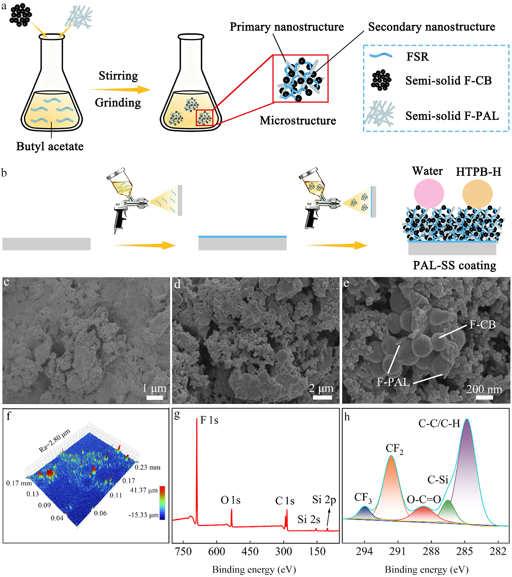
First, a suitable amount of the FSR was dissolved in 6 g of butyl acetate under magnetic stirring. Subsequently, various proportions of semi-solid F-PAL nanorods and F-CB nanoparticles, with a total mass of 4.6 g, were sequentially introduced into the solution. The resulting mixture was stirred at 1000 rpm for 10 min while simultaneously being mechanically ground with zirconia beads (m zirconia beads:m suspension = 1:2) to obtain a uniformly superamphiphobic functional-layer suspension (Fig. 1a). The hierarchical structure of the PAL-SS coating can be regulated by controlling: (1) the mass ratio of F-CB to F-PAL (from 1:15 to 5:11); and (2) the FSR content (from 0.9 to 4.5 wt.%).
Schematic representations of the preparation of the (a) superamphiphobic functional-layer suspension and (b) PAL-SS coating. (c–e) SEM images and (f) 3D profiler image of the PAL-SS coating (Ra stands for arithmetic average roughness). (g) XPS survey spectrum and (h) high-resolution C 1s spectrum of the PAL-SS coating.

Figure 1 Long description
The figure contains eight panels labeled a through h, covering preparation schematics, coating morphology, surface roughness and surface chemistry of a PAL-SS coating, where PAL-SS refers to the coating formed from palygorskite nanorods and carbon black nanoparticles bound by a fluorinated silicone resin. Panel a shows a schematic of suspension preparation. Butyl acetate is the solvent. Stirring and grinding steps are labeled. The resulting mixture contains microstructures with labeled primary nanostructure and secondary nanostructure components. The secondary nanostructure key identifies three components: FSR, semi-solid F-CB and semi-solid F-PAL. Panel b shows a schematic of the spray application process. A spray gun applies the suspension onto a flat substrate in two steps, producing the PAL-SS coating. Water and HTPB-H are labeled above the final coated surface. Panel c is a scanning electron microscopy image with a scale bar of 1 micrometer, showing the surface morphology at high magnification with a rough, clustered texture. Panel d is a scanning electron microscopy image with a scale bar of 2 micrometers, showing a wider view of the same surface with irregular aggregated structures. Panel e is a scanning electron microscopy image with a scale bar of 200 nanometers, showing individual labeled structures. Two arrows identify F-CB and F-PAL components on the surface. Panel f is a 3D profiler image of the coating surface. The roughness value Ra is labeled as 2.80 micrometers. The vertical scale spans from negative 15.33 micrometers to 41.37 micrometers. Horizontal scale markings show values of 0.04, 0.06, 0.09, 0.13, 0.15, 0.17 and 0.17. Panel g is an X-ray photoelectron spectroscopy survey spectrum. The x-axis is labeled binding energy in electronvolts, ranging from approximately 150 to 750 electronvolts. The y-axis shows intensity. Labeled peaks are F 1s, O 1s, C 1s, Si 2p and Si 2s. Panel h is a high-resolution C 1s spectrum. The x-axis is labeled binding energy in electronvolts, ranging from 282 to 294 electronvolts. The y-axis shows intensity. Five labeled component peaks are shown: C-C/C-H, CF subscript 2, CF subscript 3, C-Si and O-C=O.
Preparation of PAL-SS coatings
The PAL-SS coating was fabricated on aluminium alloy substrates (10 cm × 10 cm) using a two-step spray-coating process. First, 1 mL of FSR solution was sprayed onto the aluminium alloy substrate under a pressure of 0.1 MPa at a distance of 15 cm. After curing at room temperature for 1 h, a bonding layer was formed. Subsequently, 5 mL of the superamphiphobic functional-layer suspension was sprayed onto the preformed bonding layer under the same pressure and distance. Finally, the PAL-SS coating was obtained after curing at room temperature for 12 h (Fig. 1b). In this coating, F-PAL nanorods serve as the primary nanostructure and reinforcing component, while F-CB nanoparticles act as the secondary nanostructure and photothermal component. FSR functions as a ‘bridge’ that interconnects F-PAL and F-CB. The three components synergistically endow the coating with excellent superamphiphobicity, photothermal performance and mechanical stability. The resulting coating exhibits a thickness of ∼60 μm and an ultralow fabrication cost of only USD 13.9 m–2 (Fig. S1). Furthermore, large-area fabrication of the PAL-SS coating was achieved (Fig. S2), and the coating can be rapidly removed at the end of its service life via abrasion with sandpaper (Fig. S3).
Results and discussion
Surface morphology and chemical composition of the PAL-SS coatings
The successful surface fluorination of F-PAL and F-CB was confirmed by Fourier-transform infrared (FTIR) spectroscopy (Fig. S4). Strong absorption peaks observed at 1200 and 1154 cm–1 are characteristic of C–F stretching vibrations, demonstrating that the perfluoroalkyl chains were successfully grafted onto the surfaces of PAL and CB, thereby effectively reducing their surface energy. The degree of fluorination of F-PAL was further quantified by X-ray photoelectron spectroscopy (XPS). F-PAL exhibits a fluorine content of 49.04 at.% (Table S1). In addition, the chemical stability of F-PAL was evaluated by immersion in 1 M HCl, 1 M NaOH and 1 M NaCl solutions. After 3 h, no wetting phenomena were observed (Fig. S5), demonstrating that F-PAL possesses excellent chemical stability.
The surface morphology of the PAL-SS coating was investigated using scanning electron microscopy (SEM). As shown in Fig. 1c, the coating exhibits pronounced micro-scale protrusions distributed across the surface. This is mainly attributed to the FSR adhesive bonding F-PAL and F-CB together. High-magnification SEM images further reveal that the coating surface exhibits a multiscale nanostructure accompanied by abundant pores (Fig. 1d,e). The one-dimensional F-PAL nanorods serve as the primary nanostructure, while F-CB nanoparticles act as the secondary nanostructure. As a result, the coating possesses a multiscale hierarchical micro-/nanostructure with a surface roughness of 2.80 μm (Fig. 1f), which improves the superamphiphobicity of the coating (Deng et al., Reference Deng, Mammen, Butt and Vollmer2012; Lu et al., Reference Lu, Sathasivam, Song, Crick, Carmalt and Parkin2015; Pan et al., Reference Pan, Guo, Björnmalm, Richardson, Li and Peng2018). In addition, F-PAL and F-CB nanoparticles are uniformly dispersed and interconnected by FSR (Fig. 1d,e), which improves mechanical stability (Wei et al., Reference Wei, Zhang, Cao, Huo, Huang and Zhang2023b, Reference Wei, Mao, Li and Zhang2025).
The chemical composition of the PAL-SS coating was analysed by FTIR spectroscopy (Fig. S6). The broad peak at 3412 cm–1 is attributed to –OH functional groups, while the characteristic peaks at 1034, 782 and 468 cm–1 correspond to Si–O–Si stretching vibrations (Li et al., Reference Li, Hu, Li, Wei and Zhang2019). In addition, the presence of C–F groups is confirmed by the absorption peaks at 1206 and 1148 cm–1 (Wei et al., Reference Wei, Liang and Zhang2023a). The peak at 1732 cm–1 is assigned to the O–C=O group, originating primarily from the FSR adhesive (Wei et al., Reference Wei, Liang and Zhang2023a).
XPS was employed to further investigate the surface chemical composition of the PAL-SS coating. As shown in Fig. 1g, characteristic peaks corresponding to F 1s (689 eV), O 1s (533 eV), C 1s (285 eV), Si 2s (154 eV) and Si 2p (103 eV) were clearly observed (Zhang et al., Reference Zhang, Wei, Tian, Liang and Zhang2022). The atomic ratio of C, O, F and Si was determined to be 9.8:2.2:10.1:1, with the F content reaching as high as 43.70 at.% (Table S2). Such a high F content indicates the presence of abundant –Si(CH2)2(CF2)7CF3 on the coating surface, which is responsible for the low surface energy of the coating (Wei et al., Reference Wei, Zhang, Cao, Huo, Huang and Zhang2023b). The C 1s peak can be assigned to CF3 (294.0 eV), CF2 (291.6 eV), O–C=O (288.7 eV), C–Si (286.5 eV) and C–C/C–H (284.8 eV; Fig. 1h). Energy-dispersive X-ray spectroscopy (EDS) analysis further confirms that the PAL-SS coating surface is composed primarily of C, F, O and Si (Fig. S7 & Table S3). The elemental mapping results reveal a uniform distribution of these elements across the surface (Fig. S8), demonstrating the excellent chemical homogeneity of the coating.
Effects of F-CB/F-PAL mass ratio
The F-CB/F-PAL mass ratio plays a critical role in determining the superamphiphobicity, photothermal performance, and mechanical stability of the PAL-SS coating. The one-dimensional F-PAL nanorods mainly act as the primary nanostructure and mechanical reinforcement phase, whereas the F-CB nanoparticles mainly serve as the secondary nanostructure and photothermal component. The F-CB nanoparticles deposited on and between the F-PAL nanorods help create the hierarchical nanostructures required for efficient air trapping.
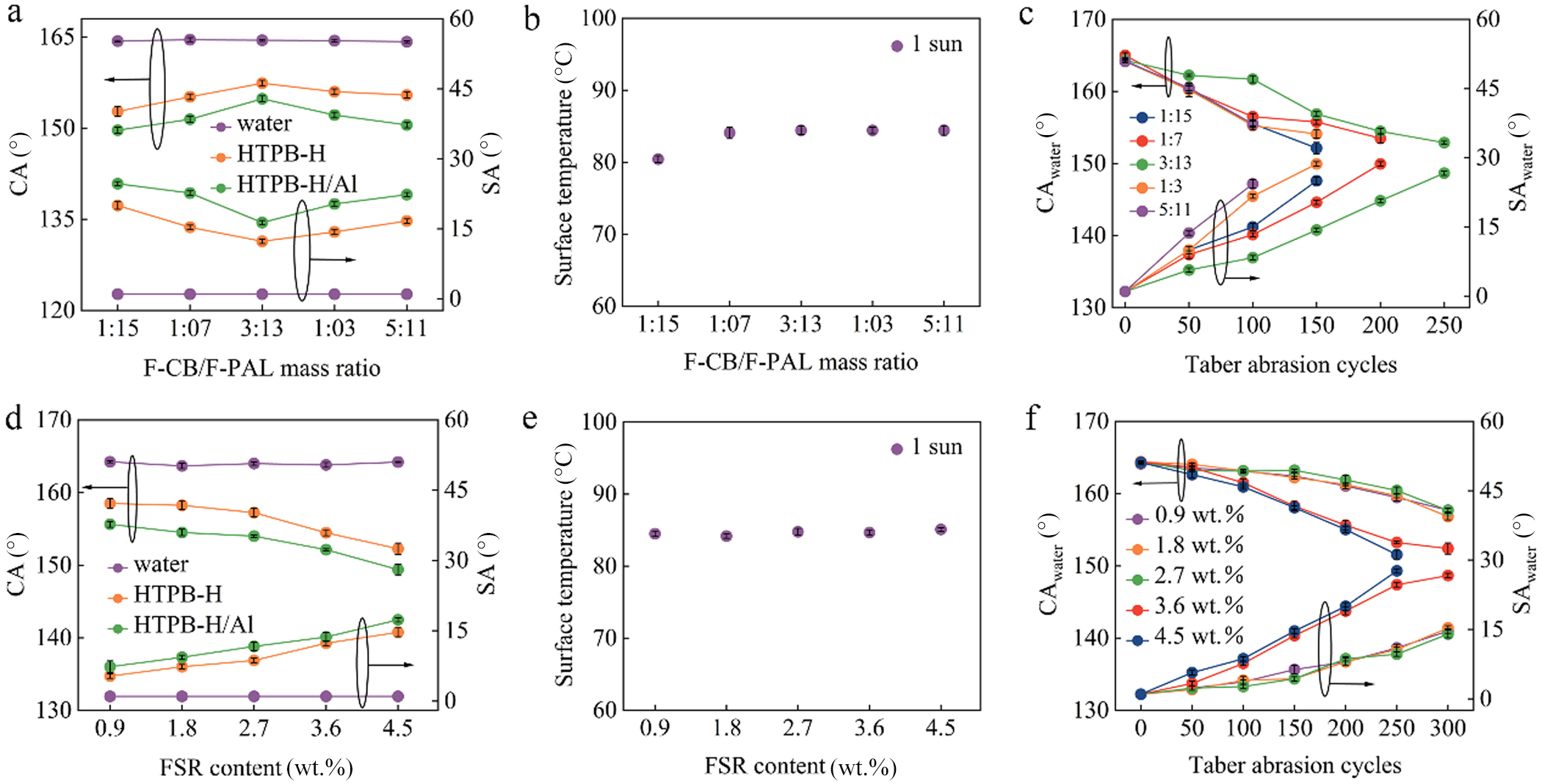
As the F-CB/F-PAL mass ratio increases, the superamphiphobicity of the coating first increases and then decreases (Fig. 2a). When the F-CB/F-PAL mass ratio is lower than 3:13, the amount of F-CB nanoparticles is insufficient to fully construct the secondary nanostructure, resulting in an incomplete multiscale hierarchical micro-/nanostructure (Zhang et al., Reference Zhang, Xu, Zhang, Ma, Wang and Huang2021a). Consequently, the air-trapping capability is limited, leading to inferior superamphiphobicity. With increasing F-CB content, complete multiscale hierarchical micro-/nanostructures are formed, which reduces the solid–liquid contact area and increases superamphiphobicity (Zhang et al., Reference Zhang, Xu, Zhang, Ma, Wang and Huang2021a). However, when the F-CB/F-PAL mass ratio exceeds 3:13, excessive F-CB tends to aggregate and partially cover the PAL nanorod framework, thereby increasing the solid–liquid contact area and weakening the superamphiphobicity (Zhang et al., Reference Zhang, Xu, Zhang, Ma, Wang and Huang2021a).
Effects of the F-CB/F-PAL mass ratio on the (a) superamphiphobicity, (b) photothermal performance and (c) mechanical stability of the PAL-SS coatings. The FSR content was 4.5 wt.%. Effects of the FSR content on the (d) superamphiphobicity, (e) photothermal performance and (f) mechanical stability of the PAL-SS coatings. The F-CB/F-PAL mass ratio was 3:13.
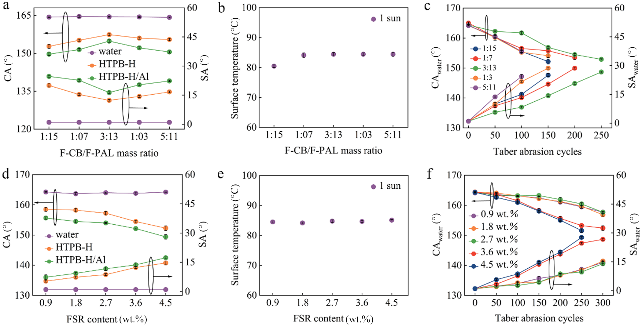
Figure 2 Long description
Panel a shows the effect of F-CB over F-PAL mass ratio on contact angle and sliding angle. The x-axis is labeled F-CB over F-PAL mass ratio with values 1:15, 1:07, 3:13, 1:03, 5:11. The left y-axis shows contact angle in degrees from 120 to 165 and the right y-axis shows sliding angle in degrees from 0 to 60. Water, HTPB-H and HTPB-H Al are plotted, showing an increase in contact angle and decrease in sliding angle as the ratio increases. Panel b displays surface temperature against F-CB over F-PAL mass ratio, with the x-axis labeled similarly. The y-axis shows surface temperature in degrees Celsius from 60 to 100, with a single series for 1 sun, indicating stable temperature across ratios. Panel c illustrates contact angle and sliding angle over Taber abrasion cycles. The x-axis ranges from 0 to 250 cycles, with the left y-axis for contact angle from 130 to 170 degrees and the right y-axis for sliding angle from 0 to 60 degrees. Different mass ratios are plotted, showing durability with varying angles over cycles. Panel d examines FSR content's effect on contact angle and sliding angle. The x-axis is labeled FSR content in weight percent with values 0.9, 1.8, 2.7, 3.6, 4.5. The left y-axis shows contact angle from 130 to 170 degrees and the right y-axis shows sliding angle from 0 to 60 degrees. Water, HTPB-H and HTPB-H Al are plotted, showing increased contact angle and decreased sliding angle with higher FSR content. Panel e shows surface temperature against FSR content, with the x-axis labeled similarly. The y-axis shows surface temperature from 60 to 100 degrees Celsius, with a single series for 1 sun, indicating stable temperature across FSR content. Panel f presents contact angle and sliding angle over Taber abrasion cycles, with the x-axis ranging from 0 to 300 cycles. The left y-axis shows contact angle from 130 to 170 degrees and the right y-axis shows sliding angle from 0 to 60 degrees. Different FSR contents are plotted, showing durability with varying angles over cycles. Overall, the graphs demonstrate how mass ratio and FSR content affect the superamphiphobicity, photothermal performance and mechanical stability of PAL-SS coatings, highlighting trends in contact angle, sliding angle and temperature stability.
Regarding photothermal performance, increasing the F-CB/F-PAL mass ratio from 1:15 to 2:14 leads to a gradual improvement in photothermal performance (Fig. 2b) owing to the increased light absorption stemming from the greater F-CB content (Wei et al., Reference Wei, Liang, Mao, Li and Zhang2024b). With further increases in the mass ratio, the photothermal performance reaches a plateau and remains nearly unchanged.
Regarding mechanical stability, as the F-CB/F-PAL mass ratio increases, the mechanical stability of the coating initially improves and subsequently decreases, with the greatest mechanical stability obtained at a mass ratio of 3:13 (Fig. 2c). At low F-CB contents, the secondary nanostructure is not sufficiently developed, and the interactions among the coating components remain limited, resulting in relatively poor mechanical stability. However, when excessive F-CB was introduced, the reinforcing effect of the PAL nanorods was weakened, thereby reducing the mechanical stability (Mao et al., Reference Mao, Wei, Li, Li, Huang and Zhang2024). Based on the combined optimization of superamphiphobicity, photothermal performance and mechanical stability, the PAL-SS coating with an F-CB/F-PAL mass ratio of 3:13 was selected for subsequent investigation.
Effects of the FSR content
The FSR content also plays a crucial role in determining the superamphiphobicity, photothermal performance and mechanical stability of the PAL-SS coating. It should be noted that the FSR has relatively low surface energy (CAwater = 98.6°). Such an adhesive can improve mechanical stability without significantly sacrificing superamphiphobicity.
As the FSR content increases, the superamphiphobicity of the coating gradually deteriorates (Fig. 2d). This behaviour can be attributed to the FSR, which leads to an overall increase in the surface energy of the coating and consequently weakens its superamphiphobicity (Wei et al., Reference Wei, Zhang, Cao, Huo, Huang and Zhang2023b). Notably, the FSR content has no significant influence on the photothermal performance of the coating (Fig. 2e), as the photothermal response is primarily governed by F-CB. With respect to mechanical stability, as the FSR content increases, the mechanical stability of the coating shows an initial improvement followed by a decline (Fig. 2f). When the FSR content is 2.7 wt.%, the coating demonstrates optimal mechanical stability. Considering the trade-off between superamphiphobicity and mechanical stability, the PAL-SS coating with an FSR content of 2.7 wt.% was selected for subsequent investigation.
Static and dynamic superamphiphobicity of the PAL-SS coatings
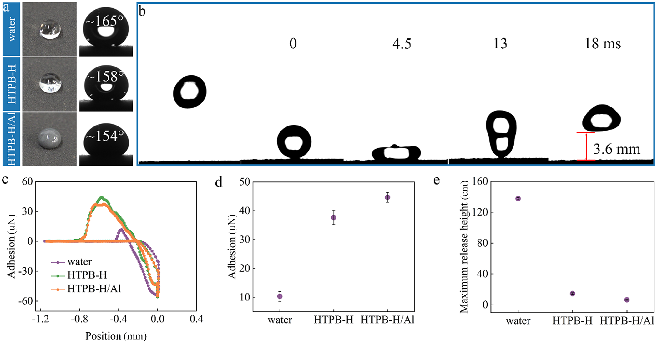
After systematic optimization, the PAL-SS coating exhibits excellent static superamphiphobicity towards both water and high-viscosity, low-surface-tension and complex multicomponent liquids. As shown in Fig. 3a, droplets of water, HTPB-H and HTPB-H/Al maintain nearly spherical shapes on the coating surface. The corresponding CAs reach 165°, 158° and 154°, respectively, accompanied by low SAs of 1°, 8° and 11°, respectively. Moreover, the coating also exhibits excellent superamphiphobicity towards other typical low-surface-tension liquids, including glycerol, vegetable oil and n-hexadecane. The corresponding CAs and SAs are shown in Fig. S9, all of which confirm the superamphiphobicity of the coating. When the coating was immersed in water, a pronounced silver mirror effect was observed (Fig. S10), indicating the presence of a stable trapped air layer at the solid–liquid interface. These results confirm that liquids reside in the Cassie–Baxter state on the PAL-SS coating. Furthermore, when the droplets (10 μL) of water, HTPB-H and HTPB-H/Al on the syringe needle were lifted after contact with the coating, no observable adhesion was detected (Fig. S11), demonstrating extremely weak solid–liquid adhesion. This behaviour was further quantified by direct solid–liquid adhesion force measurements. The measured adhesion forces are as low as 12 μN for water, 37 μN for HTPB-H and 44 μN for HTPB-H/Al (Fig. 3c,d). These results demonstrate that the PAL-SS coating exhibits excellent static superamphiphobicity for high-viscosity, low-surface-tension and complex multicomponent liquids, which can be attributed to the synergistic effect of the low surface energy and the multiscale hierarchical micro-/nanostructure. In addition, the coating exhibits excellent reproducibility across various batches and substrates (copper, steel and glass; Figs S12 & S13).
Photographs of the coating (a) with various droplets (∼10 μL) and (b) being impacted by a water droplet. (c, d) The adhesion forces between various droplets and the PAL-SS coating. (e) The maximum release height of various droplets on the PAL-SS coating.
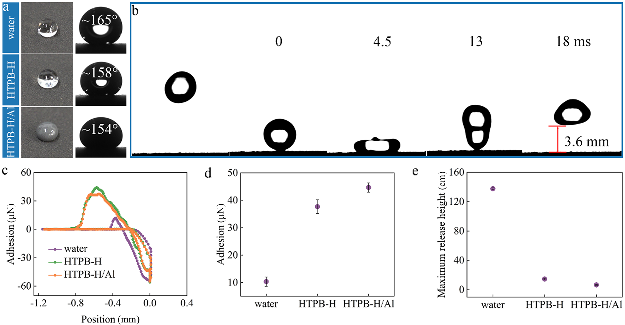
Figure 3 Long description
The image A showing three droplet images labeled water, HTPB-H and HTPB-H/Al. Each droplet image includes a contact angle label: 165 degree for water, 158 degree for HTPB-H and 154 degree for HTPB-H/Al. The image B showing a droplet impact sequence with time labels 0, 4.5, 13 and 18 millisecond. A scale label reads 3.6 millimeter. The image C showing a line graph with the horizontal axis labeled Position (millimeter) ranging from negative 1.2 to 0.4 and the vertical axis labeled Adhesion (microNewton) ranging from negative 60 to 60. The legend lists three series: water, HTPB-H and HTPB-H/Al. Each series rises from near 0 microNewton at about negative 1.2 millimeter to a positive peak around 40 to 50 microNewton near about negative 0.8 millimeter, then decreases and crosses near 0 microNewton around about negative 0.5 millimeter and continues to a negative trough around negative 50 to negative 60 microNewton near about negative 0.2 millimeter. The three series follow similar shapes, with small separations between the curves around the peak and trough regions. The image D showing a dot plot with the vertical axis labeled Adhesion (microNewton) ranging from 0 to 50 and category labels water, HTPB-H and HTPB-H/Al on the horizontal axis. The plotted values are approximately: water about 12 microNewton, HTPB-H about 37 microNewton and HTPB-H/Al about 44 microNewton. The highest plotted value is HTPB-H/Al and the lowest plotted value is water. The image E showing a dot plot with the vertical axis labeled Maximum release height (centimeter) ranging from 0 to 160 and category labels water, HTPB-H and HTPB-H/Al on the horizontal axis. The plotted values are approximately: water about 140 centimeter, HTPB-H about 120 centimeter and HTPB-H/Al about 120 centimeter. The highest plotted value is water and the lowest plotted values are HTPB-H and HTPB-H/Al.
The coating also exhibits excellent dynamic superamphiphobicity towards the aforementioned liquids. A 10 μL water droplet released from a height of 1 cm can rebound on the coating surface for up to 13 consecutive bounces (Movie S1), with an initial solid–liquid contact time of 13.0 ms and a rebound height of 3.6 mm (Fig. 3b). Moreover, when a continuous water jet impinges on the coating surface, the liquid completely rebounds without any residual adhesion (Fig. S14). To further evaluate the dynamic superamphiphobicity of the PAL-SS coating, droplet impact tests were conducted by releasing 10 μL droplets from varying heights onto a surface inclined at 20°. The maximum release height is defined as the highest droplet release height at which no liquid adhesion occurs upon impact. A higher maximum release height indicates superior dynamic superamphiphobicity. The maximum release heights for water, HTPB-H and HTPB-H/Al droplets were determined to be 137, 14 and 6 cm, respectively (Fig. 3e), further confirming the outstanding dynamic superamphiphobicity of the coating.
Stability of the PAL-SS coatings
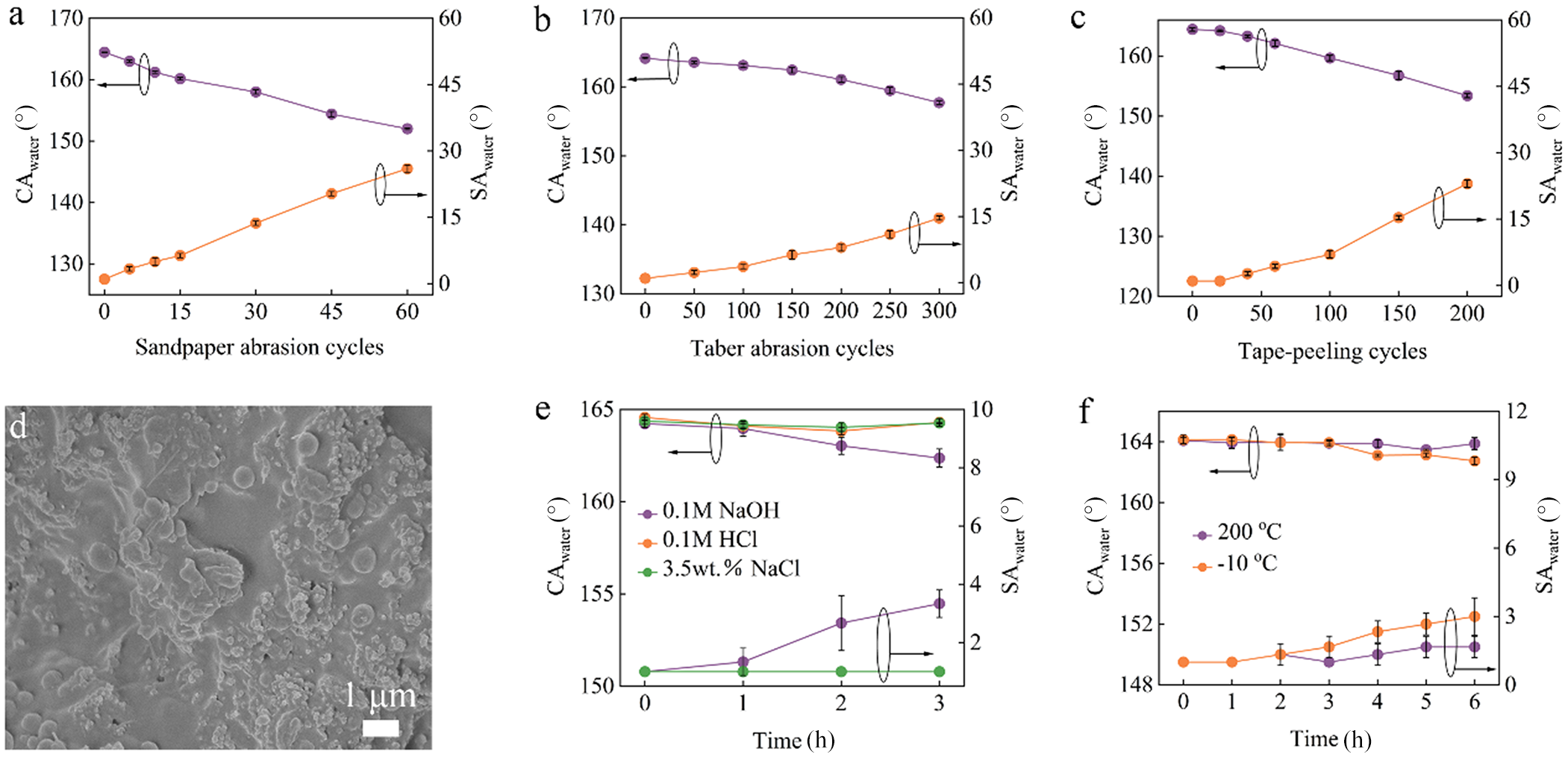
The mechanical stability of the PAL-SS coating was systematically evaluated using sandpaper abrasion, Taber abrasion and tape-peeling tests. For the sandpaper abrasion test, a load of 200 g was applied using 1000 grit sandpaper, with an abrasion distance of 20 cm per cycle. As the number of abrasion cycles increased, the CAwater gradually decreased while the SAwater increased (Fig. 4a). Nevertheless, even after 60 abrasion cycles (1.2 m), the coating maintained excellent superamphiphobicity, with a CAwater exceeding 150° and an SAwater below 30° (Figs 4a & S15a). Consistent results were observed in the Taber abrasion tests, further demonstrating the outstanding mechanical stability of the coating. Even after 300 Taber abrasion cycles using CS-10 wheels under a load of 125 g, the coating still exhibited a high CAwater of 158° and a low SAwater of 15° (Figs 4b & S15b). The mechanical stability of the coating was further examined by tape-peeling tests using 3M adhesive tape under a load of 200 g. After 200 peeling cycles, the coating remained highly superamphiphobic, with a CAwater of 152° and an SAwater of 25° (Figs 4c & S15c). The excellent mechanical stability is primarily attributed to the strong binding effect of FSR within the superamphiphobic functional layer, which significantly increases the interparticle adhesion between F-PAL and F-CB (Wei et al., Reference Wei, Zhang, Cao, Huo, Huang and Zhang2023b, Reference Wei, Mao, Li and Zhang2025). Furthermore, the inherent rigidity and high aspect ratio of PAL nanorods provide a reinforcing effect (Mao et al., Reference Mao, Wei, Li, Li, Huang and Zhang2024). In addition, the underlying FSR bonding layer effectively improves the interfacial adhesion between the superamphiphobic functional layer and the aluminium alloy substrate (Li et al., Reference Li, Li, Zhao, Tian and Zhang2018). As a result, the coating is able to retain its hierarchical micro-/nanostructure even after severe mechanical damage (Fig. 4d). Compared with typical fluorinated or functionalized silica-based coatings, the PAL-SS coating shows superior superamphiphobicity towards high-viscosity, low-surface-tension and complex multicomponent liquids, as well as significantly better mechanical stability (Table S4). In addition, the coating adhesion on various substrates (aluminium, copper, stainless steel) was evaluated using the hundred-grid adhesion strength test, and the results demonstrate good adhesion on all three substrates (Fig. S16).
Changes in the CAwater and SAwater of the PAL-SS coating during the (a) sandpaper abrasion test, (b) Taber abrasion test and (c) tape-peeling test. (d) SEM image of the PAL-SS coating after 300 cycles of Taber abrasion. Changes in the CAwater and SAwater of the PAL-SS coating during the (e) corrosive liquids immersion tests and (f) high-/low-temperature treatment tests. The black ovals with arrows indicate that the corresponding data series refers to the indicated y-axis.

Figure 4 Long description
The image A showing a line graph with two vertical axes. The horizontal axis label is “Sandpaper abrasion cycles” with ticks 0, 15, 30, 45, 60. The left vertical axis label is “CAwater (°)” with ticks 130, 140, 150, 160, 170. The right vertical axis label is “SAwater (°)” with ticks 0, 15, 30, 45, 60. One series on the left axis starts near 170 at 0 cycles and decreases to about 155 at 60 cycles. One series on the right axis starts near 0 at 0 cycles and increases to about 30 at 60 cycles. The image B showing a line graph with two vertical axes. The horizontal axis label is “Taber abrasion cycles” with ticks 0, 50, 100, 150, 200, 250, 300. The left vertical axis label is “CAwater (°)” with ticks 130, 140, 150, 160, 170. The right vertical axis label is “SAwater (°)” with ticks 0, 15, 30, 45, 60. One series on the left axis is near 165 at 0 cycles and decreases to about 158 at 300 cycles. One series on the right axis is near 0 at 0 cycles and increases to about 15 at 300 cycles. The image C showing a line graph with two vertical axes. The horizontal axis label is “Tape-peeling cycles” with ticks 0, 50, 100, 150, 200. The left vertical axis label is “CAwater (°)” with ticks 120, 130, 140, 150, 160, 170. The right vertical axis label is “SAwater (°)” with ticks 0, 15, 30, 45, 60. One series on the left axis is near 170 at 0 cycles and decreases to about 152 at 200 cycles. One series on the right axis is near 0 at 0 cycles and increases to about 25 at 200 cycles. The image D showing a micrograph with a scale bar labeled “1 μm”. The image E showing a line graph with two vertical axes and a legend listing “0.1M NaOH”, “0.1M HCl” and “3.5wt.% NaCl”. The horizontal axis label is “Time (h)” with ticks 0, 1, 2, 3. The left vertical axis label is “CAwater (°)” with ticks 150, 155, 160, 165. The right vertical axis label is “SAwater (°)” with ticks 0, 2, 4, 6, 8, 10. Three series on the left axis lie between about 162 and 165 from 0 to 3 hours. Three series on the right axis lie between about 0 and 4 from 0 to 3 hours. The image F showing a line graph with two vertical axes and a legend listing “200 °C” and “-10 °C”. The horizontal axis label is “Time (h)” with ticks 0, 1, 2, 3, 4, 5, 6. The left vertical axis label is “CAwater (°)” with ticks 148, 152, 156, 160, 164. The right vertical axis label is “SAwater (°)” with ticks 0, 3, 6, 9, 12. Two series on the left axis lie near 162 to 164 from 0 to 6 hours. Two series on the right axis rise from near 0 at 0 hours to about 3 at 6 hours.
In addition, the chemical stability of the PAL-SS coating was evaluated by immersion tests in corrosive solutions (Fig. 4e). After immersion in 0.1 M HCl(aq) and 3.5 wt.% NaCl(aq) for 3 h, no noticeable degradation in the superamphiphobicity of the coating was observed. When immersed in 0.1 M NaOH(aq), a slight decrease in superamphiphobicity occurred. However, the coating remained superamphiphobic even after 3 h of exposure. These results demonstrate the excellent chemical stability of the PAL-SS coating, which can be primarily attributed to the chemical inertness of its constituent materials (Wei et al., Reference Wei, Zhang, Cao, Huo, Huang and Zhang2023b).
The thermal stability of the PAL-SS coating was investigated through high-/low-temperature treatments (Fig. 4f). After exposure to either 200°C or –10°C for 1 h, the superamphiphobicity of the coating showed no obvious change. Even after prolonged treatment for 6 h under these conditions, only a slight deterioration was observed, confirming the outstanding thermal stability of the coating.
In addition, the environmental stability of the PAL-SS coating was further evaluated through ultraviolet (UV) aging (365 nm, 12 W, 480 h), sand drop abrasion (10 cm height, 500 g, 45° inclination), simulated raindrop impact (∼40 μL droplets, 50–60 droplets min–1, 10 cm height, 45° inclination, 120 min), freeze–thaw cycling (60 μL droplets, 10 cycles) and practical outdoor exposure (Lanzhou, Gansu, P.R. China, 480 h) tests. All results show that the coating retains superamphiphobicity, with CAwater >159° and SAwater <13° (Figs S17 & S18), indicating excellent environmental stability.
Furthermore, the superamphiphobic functional-layer suspension shows excellent storage stability. Although slight sedimentation occurs after 14 days of storage at room temperature in a sealed container, it can be fully redispersed by simple stirring. The coating prepared from this redispersed suspension exhibits superamphiphobicity and mechanical stability comparable to those of the freshly prepared dispersion (Fig. S19).
Application in anti-adhesion and anti-icing of the PAL-SS coatings
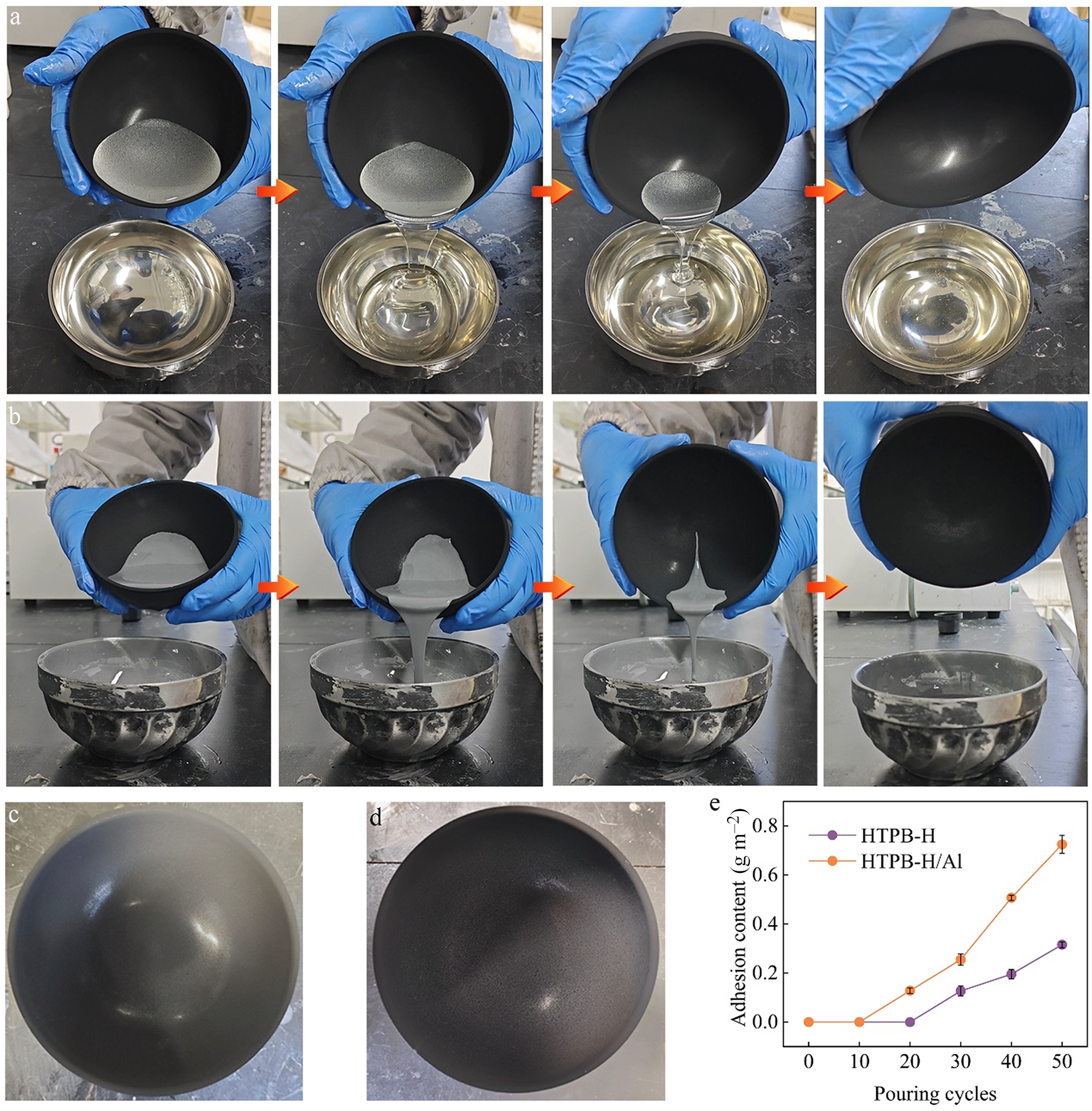
The anti-adhesion performance of the PAL-SS coating towards high-viscosity, low-surface-tension and complex multicomponent liquids was investigated. HTPB-H, a representative liquid characterized by strong adhesion, high viscosity and low surface tension, was selected as the test medium. Specifically, 100 g of HTPB-H was poured into a bowl coated with the PAL-SS coating, after which the adhesion of HTPB-H on the surface was visually examined and quantitatively measured. The results show that no detectable HTPB-H adhesion remained on the coating surface after 20 repeated tests (Fig. 5a,c & Movie S2). Even after 50 test cycles, the adhesion mass of HTPB-H was as low as 0.32 g m–2 (Fig. 5e), demonstrating the excellent anti-adhesion performance of the PAL-SS coating toward HTPB-H.
The first pouring process of (a) HTPB-H and (b) HTPB-H/Al from the PAL-SS-coated bowl. (c) Photograph of the PAL-SS-coated bowl after repeating the pouring process of HTPB-H for 20 cycles. (d) Photograph of the PAL-SS-coated bowl after repeating the pouring process of HTPB-H/Al for 10 cycles. (e) Changes in the adhesion contents of the HTPB-H and HTPB-H/Al during the pouring process.

Figure 5 Long description
The images depict the pouring process of HTPB-H and HTPB-H/Al from a PAL-SS-coated bowl. The first row shows the initial pouring of HTPB-H, while the second row shows HTPB-H/Al. Image (c) displays the bowl after 20 cycles of HTPB-H pouring and image (d) shows the bowl after 10 cycles of HTPB-H/Al pouring. Image (e) is a graph illustrating the adhesion content of HTPB-H and HTPB-H/Al over 50 pouring cycles, with the x-axis labeled 'Pouring cycles' and the y-axis labeled 'Adhesion content (g m superscript -2)'. The graph indicates increasing adhesion content with more cycles for both substances.
To further evaluate the anti-adhesion performance against more complex liquids, solid aluminium powder was introduced into HTPB-H to form an HTPB-H/Al suspension. As shown by the experimental results, no observable adhesion of HTPB-H/Al occurred on the coating surface after 10 repeated tests (Fig. 5b,d & Movie S3). Even after 50 cycles, the adhered mass remained limited to 0.70 g m–2 (Fig. 5e), confirming that the PAL-SS coating also exhibits outstanding anti-adhesion performance towards HTPB-H/Al. This superior anti-adhesion behaviour can be primarily attributed to the coating’s excellent superamphiphobicity and remarkable stability.
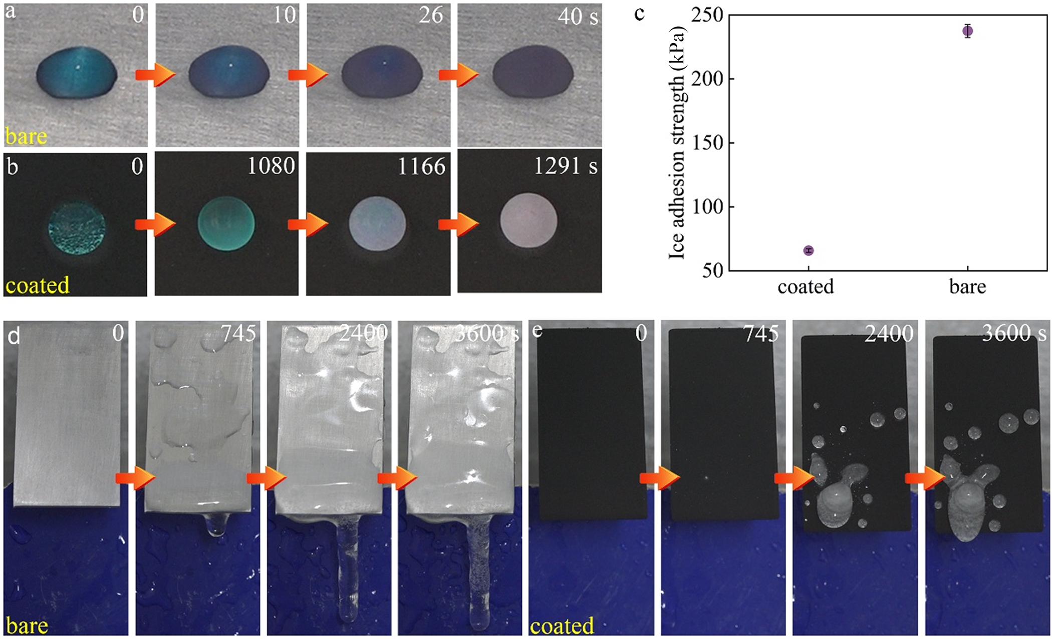
Furthermore, the passive anti-icing performance of the coating was systematically evaluated under conditions of –10°C and 80% relative humidity (RH). On the bare aluminium alloy substrate, a 60 μL water droplet completely froze within only 40 s (Fig. 6a & Movie S4). In contrast, after being coated with PAL-SS, the freezing time of the water droplet was increased to 1291 s (Fig. 6b & Movie S4), representing an ∼30-fold increase compared to the uncoated substrate.
Static icing process of water droplets on the (a) bare aluminium alloy and (b) PAL-SS-coated aluminium alloy substrates. (c) Ice adhesion strength on the bare aluminium alloy and PAL-SS-coated aluminium alloy substrates. Dynamic icing process of water droplets on the (d) bare aluminium alloy and (e) PAL-SS-coated aluminium alloy substrates.

Figure 6 Long description
The image A showing a sequence of four frames of a droplet on a surface. The frames are labeled 0, 10, 26 and 40 s. The image B showing a sequence of four frames of a droplet on a surface. The frames are labeled 0, 1080, 1166 and 1291 s. The image C showing a scatter plot. The x-axis has two categories labeled coated and bare. The y-axis label is Ice adhesion strength (kPa), ranging from 50 to 250 with tick marks at 50, 100, 150, 200 and 250. One point is plotted above coated at about 70. One point is plotted above bare at about 240. The image D showing a sequence of four frames of a vertical rectangular sample above a container. The frames are labeled 0, 745, 2400 and 3600 s. The image E showing a sequence of four frames of a vertical rectangular sample above a container. The frames are labeled 0, 745, 2400 and 3600 s.
In addition to delaying ice formation, the PAL-SS coating significantly reduced the ice adhesion strength. The bare aluminium alloy substrate exhibited a high ice adhesion strength of 224.3 kPa, whereas this value decreased dramatically to 65.8 kPa after coating with PAL-SS (Fig. 6c). These results clearly demonstrate the excellent static anti-icing performance of the PAL-SS coating. This superior performance can be primarily attributed to the outstanding superamphiphobicity of the coating, which minimizes the solid–liquid contact area. The reduced contact area effectively suppresses heat transfer from the aluminium substrate to the water droplet, thereby delaying freezing, while simultaneously lowering the interfacial bonding strength between the ice and the substrate (Wei et al., Reference Wei, Li, Tian, Zhang, Liang and Zhang2022). Moreover, the presence of a stable air cushion trapped at the solid–liquid interface further impedes heat transfer (Wei et al., Reference Wei, Li, Tian, Zhang, Liang and Zhang2022).
The dynamic anti-icing performance of the coating was evaluated by continuously dripping water droplets (0°C, ∼40 μL per droplet, 50–60 droplets min–1) from a height of 10 cm onto samples inclined at 20°. For the bare substrate, a large amount of ice accumulated on the surface after 745 s of continuous dripping (Fig. 6d & Movie S5). In contrast, the PAL-SS-coated sample exhibited no observable ice formation after 745 s. Even after prolonged exposure of 3600 s, only a small amount of ice was present on the coated surface (Fig. 6e & Movie S5). These results clearly demonstrate the excellent dynamic anti-icing performance of the PAL-SS coating. This performance is primarily attributed to its outstanding dynamic superamphiphobicity, which minimizes the solid–liquid contact time between the coating surface and supercooled water droplets. As a result, the droplets can rebound and roll off before freezing occurs, effectively suppressing ice accumulation under dynamic icing conditions (Mao et al., Reference Mao, Wei, Li, Li, Huang and Zhang2024).
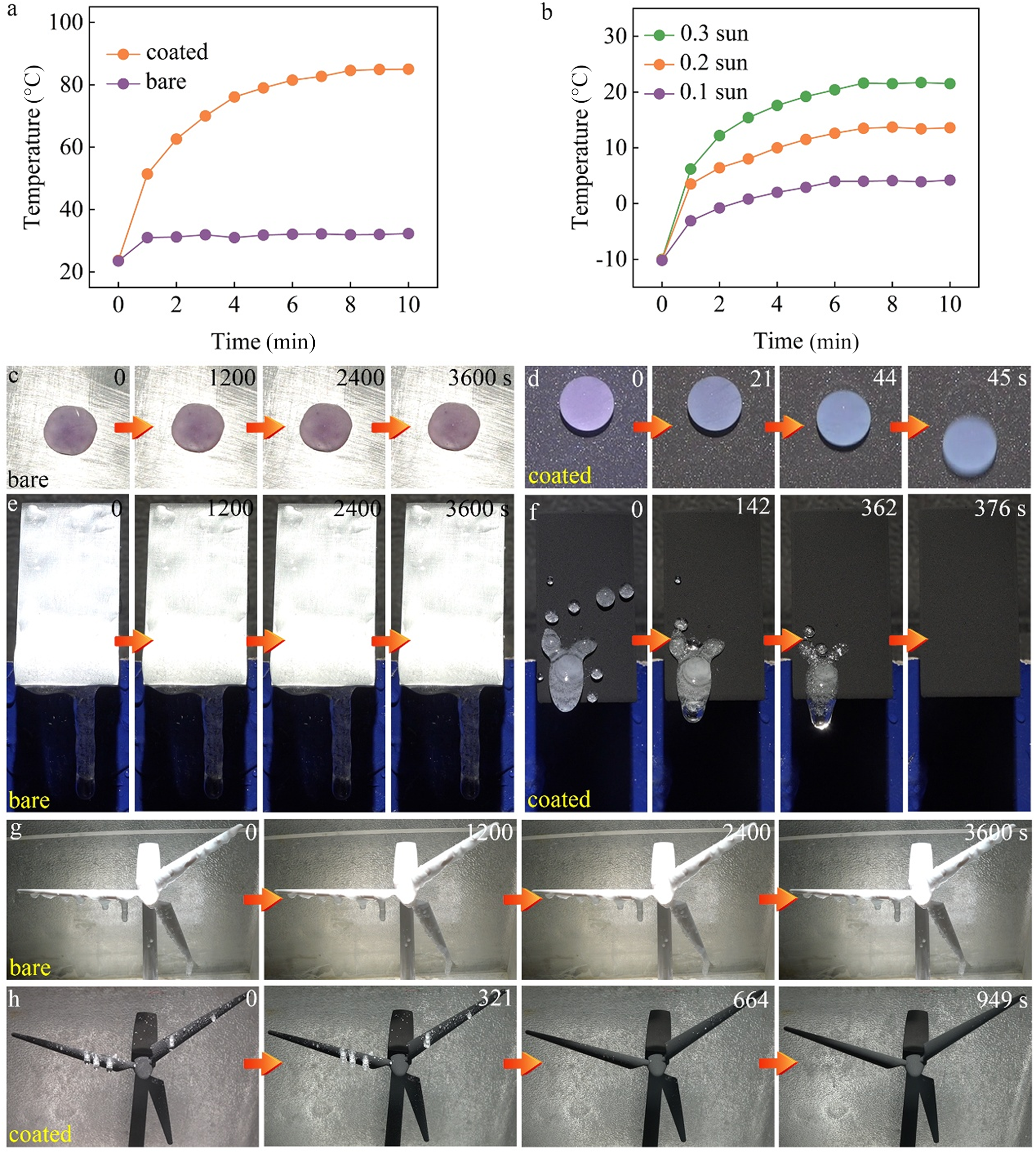
In addition, the incorporation of F-CB endows the coating with outstanding photothermal performance, as it absorbs light across a broad spectrum (UV–visible–near-infrared) and efficiently converts it into heat via non-radiative relaxation, thereby enabling efficient photothermal de-icing performance. Under an ambient temperature of 23.5°C, the surface temperature of the PAL-SS coating rapidly increased to 85°C after 10 min of irradiation at an intensity of 1 sun, whereas the bare aluminium alloy substrate exhibited a temperature increase of only ∼8°C under identical conditions (Fig. 7a). This pronounced contrast clearly demonstrates the excellent photothermal performance of the PAL-SS coating. More importantly, the coating maintains superior photothermal performance under harsh icing-relevant conditions (Fig. 7b). At –10°C, 80% RH and a low light intensity of 0.3 sun, the surface temperature of the PAL-SS coating rapidly increased from –10.1°C to 6.2°C within 1 min and further increased to 21.5°C within 10 min. Even under extremely weak illumination of 0.1 sun, the surface temperature of the coating was still able to rise above 0°C, demonstrating practical photothermal de-icing capability under realistic icing conditions.
Surface temperature changes of the bare aluminium alloy and PAL-SS-coated aluminium alloy substrates over time (a) under 1 sun in a 23.5°C, 47% RH environment and (b) under 0.1–0.3 sun in a –10°C, 80% RH environment. Photothermal de-icing process of (c,d) frozen water droplets and (e,f) large-area accumulated ice on the bare aluminium alloy and PAL-SS-coated aluminium alloy substrates. Photothermal de-icing process of large-area accumulated ice in the (g) bare wind turbine model and (h) the PAL-SS-coated wind turbine model.

Figure 7 Long description
The composite image consists of multiple sections illustrating temperature changes and de-icing processes on bare and coated surfaces. Section (a) shows a graph with temperature (°C) on the y-axis and time (min) on the x-axis, comparing coated and bare surfaces under 1 sun. The coated surface reaches higher temperatures over time compared to the bare surface. Section (b) displays a graph with temperature (°C) on the y-axis and time (min) on the x-axis, showing temperature changes under 0.1, 0.2 and 0.3 sun conditions. The coated surface consistently reaches higher temperatures than the bare surface. Sections (c) and (d) depict the photothermal de-icing process of frozen water droplets on bare and coated surfaces, respectively, with time intervals marked as 0, 1200, 2400 and 3600 seconds for bare and 0, 21, 44 and 45 seconds for coated. Sections (e) and (f) show the de-icing process of large-area accumulated ice on bare and coated surfaces, respectively, with time intervals marked as 0, 142, 362 and 376 seconds for coated. Sections (g) and (h) illustrate the de-icing process on a bare wind turbine model and a PAL-SS-coated wind turbine model, respectively, with time intervals marked as 0, 200, 400 and 3600 seconds for bare and 0, 321, 664 and 949 seconds for coated. Orange arrows indicate the progression of time in each section.
Correspondingly, frozen water droplets on the bare aluminium alloy substrate exhibited no observable melting after 3600 s under conditions of –10°C, 80% RH and 0.3 sun illumination (Fig. 7c & Movie S6). In contrast, frozen droplets on the PAL-SS coating melted within 45 s and subsequently rolled off the surface (Fig. 7d & Movie S6). A similar phenomenon was observed for large-area accumulated ice (Fig. 7e,f & Movie S7). While the bare aluminium alloy substrate remained unchanged even after 3600 s, the ice on the PAL-SS coating completely melted and detached within 376 s. These results collectively confirm that the PAL-SS coating possesses excellent photothermal de-icing performance under low-temperature, high RH and weak-light conditions, which can be attributed to the synergistic effect of efficient photothermal performance and superamphiphobicity.
To further validate the practical photothermal de-icing performance, the PAL-SS coating was applied to a wind turbine model, and photothermal de-icing experiments were conducted on the accumulated ice (Fig. 7g,h & Movie S8). The results show that ice on the bare wind turbine model could not be removed via photothermal de-icing, whereas the ice in the PAL-SS-coated wind turbine model was completely eliminated within 949 s. This demonstration highlights the strong potential of the PAL-SS coating for real-world applications in energy and infrastructure systems.
Conclusions
In summary, a PAL-based superamphiphobic coating with a simple fabrication process, low cost and excellent stability was successfully developed via a sequential spray-coating strategy. The coating consists of an FSR bonding layer and a superamphiphobic functional layer composed of FSR, F-PAL and F-CB. The F-CB/F-PAL mass ratio and the FSR content were identified as key parameters governing the coating’s superamphiphobicity, photothermal performance and mechanical stability. Through systematic optimization, the coating exhibits a multiscale hierarchical micro-/nanostructure with low surface energy, which is achieved through the synergistic combination of one-dimensional F-PAL nanorods and zero-dimensional F-CB nanoparticles. This structure endows the coating with outstanding static and dynamic superamphiphobicity, demonstrated by high CAs, low SAs and large maximum release heights towards water as well as high-viscosity, low-surface-tension and complex multicomponent liquids, including HTPB-H and HTPB-H/Al. In addition, the coating exhibits excellent mechanical, chemical and thermal stability, along with remarkable anti-adhesion performance against both HTPB-H and HTPB-H/Al. Superior anti-icing performance was also achieved, characterized by effective freezing delay, reduced ice adhesion strength and efficient photothermal de-icing under low-temperature, high-RH and weak-light conditions. Collectively, these results demonstrate that the proposed superamphiphobic coating holds strong potential for practical applications in preventing the adhesion of high-viscosity, low-surface-tension and complex multicomponent liquids and in anti-icing/de-icing under harsh environmental conditions. Despite its excellent performance, some limitations should be acknowledged. The use of fluorinated compounds raises environmental concerns, and so future work will focus on developing non-fluorinated alternatives.
Supplementary material
The supplementary material for this article can be found at https://doi.org/10.1180/clm.2026.10036.
Financial support
This work was supported by the National Natural Science Foundation of China (22505275, 22275200), Gansu Provincial Natural Science Foundation (23JRRA580, 23JRRA600, and 25JRRA480), Gansu Province Top Leading Talents Program, the Central Government-Guided Local Science and Technology Development Fund of Gansu Province (25ZYJA013), Key Cultivation Projects during the ‘15th Five-Year Plan’ Period of LICP (KCP155B10) and the Postdoctoral Fellowship Program of CPSF (GZB20250038).
Competing interests
The authors declare no none.