





Impact statement
Many AI research and development projects never leave the lab. This is partly due to the lack of effort committed to ensuring that the humans who will interact with the tool are engaged in the development. In this case, using the tools from the academic literature in an industrial context quickly demonstrated that the layouts were generic, they do not feel like they were created by a human, and the design team were unwilling to engage with the tool. Ensuring that the tool fit to brand allows the design team the ability to explore a greater range of options and have more confidence in their approach. It has shown the potential to reduce the layout development time from 2 weeks to 2 days.
1. A feeling of space in a tight envelope
In yacht design, meeting customer expectations is challenging. The customer requires a high-quality design with many vessels being unique or limited production runs that stretch current design rules or might even require type approval. The most important factor for the owner is that they feel that the design is as spacious and luxurious as possible within the limits of the hull envelope, but at the same time, all the usual engineering considerations, such as structural integrity and efficiency, must be met. A current challenge—emissions reductions—demonstrates the increasing pressure placed at concept design. Improving efficiency is driving hull forms to become more advanced to operate efficiently at multiple design speeds and that they are aligned with the latest low-emission technology in propulsion systems and regulations. This requirement pushes new hull forms that require a different internal layout to make full utilization of the space available. This is especially important because the cost of production increases rapidly with increased hull length, and inefficient designs lead to increased expense for the owner or a lower utility.
The early decisions taken in concept design are crucial for the future success of a project, both in terms of the quality of the end product and regarding management and finances, for example, the person-hours allocation and design decisions determining production costs are locked in at this stage. It is therefore crucial that these decisions are well informed. During the initial phase of designing a new yacht, the feasibilities of various hull and layout configurations are investigated. Throughout this early period, many variations of the hull or layout will be explored. This can result in an inefficient process where work has to be regularly revisited, and the impact of changes resolved multiple times. In addition, under the tight time constraints, it is difficult to demonstrate that the layout exploration for each hull has been performed thoroughly and all possibilities explored.
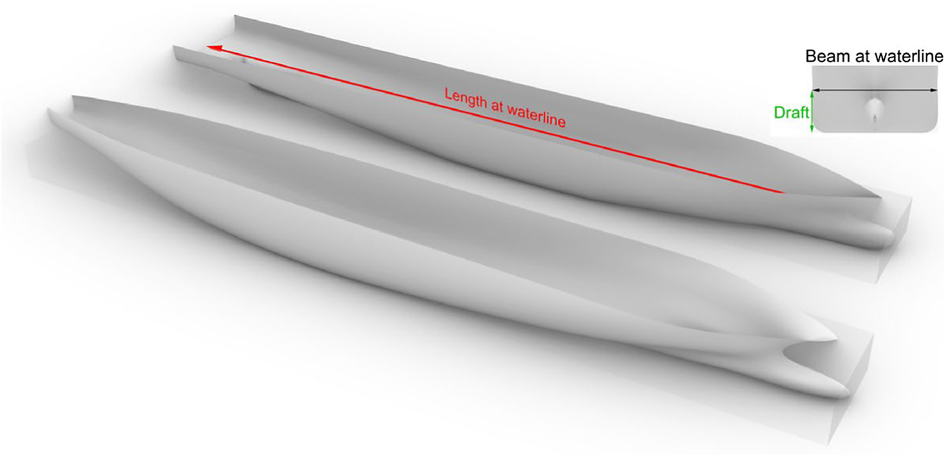
To tackle these challenges, more approaches utilizing AI are being developed. Optimization algorithms have been shown to provide an improvement in the effectiveness of designs produced at the early stages of a new project. For example, constrained efficient global optimization focuses on the early-stage design of a dredger. In this case, a six-variable design with 16 constraints is optimized. When compared with the original design, the optimization tool shows a 19% smaller resistance coefficient and 14% less steel weight (Winter et al., Reference Winter, Stein, Dijkman and Back2018). However, for a dredger, the internal layout is not a priority, and the optimization only considers the ship particulars. Alongside optimization algorithms, generative AI is providing interesting new concepts and can provide new hull forms, as shown in Figure 1 (Khan et al., Reference Khan, Goucher-Lambert, Kostas and Kaklisa2023). However, there are still issues with these approaches in the design of ship layouts, especially relating to the ownership of the Intellectual Property if images from outside of the company are used in the training set and the number of available images that are available in these settings. There is also a tendency for these designs to be outside of the design space that is feasible, as there is no physical evaluation, and such evaluations can be time-consuming to evaluate. It can also be challenging to match the company’s brand unless the data set can be biased toward the company’s own designs. Genetic algorithms are therefore still the main approaches to developing layout designs with a focus in the literature on the constraints, objectives, and numerical fitness functions around four main approaches to encoding: Intelligent Ship Arrangement (Daniels and Parsons, Reference Daniels and Parsons2008), Packing Approach (van Oers et al., Reference van Oers, Stapersma and Hopman2009), the Grid Representation (Nam et al., Reference Nam, Kim and Lee2010), and Vector Representation (Sobey et al., Reference Sobey, Blanchard, rudniewski and Savasta2019). However, there is no documentation of how well these concepts are accepted by the design team, meaning that the designs produced are likely to be generic, with no fit to the brand of the company.
Hull designs optimized using a genetic algorithm and generative AI (Khan et al., Reference Khan, Goucher-Lambert, Kostas and Kaklisa2023).
One of the most important tasks of developing a motorboat is drawing out its layout due to its major contribution to the commercial success of the boat. It is a complex enterprise due to the numerous interactions with other design subsystems. To reduce the concept design time, a number of approaches to layout optimization have been explored, but they require adaptation to represent a company’s brand and for integration into the design team. This article therefore investigates the integration within a design office and how the initial concept fits with the company’s design philosophy. To do this, an approach documented in Sobey et al. (Reference Sobey, Grudniewski and Savasta2019) is adapted for practical applications. This is achieved by focusing on the objectives rather than incorporating additional constraints to improve the efficiency of the search algorithm. A novel hierarchical approach is used to define the variables; this ensures that furniture and stairwells are placed correctly. The result is that the number of objectives can be reduced to 2, and no constraints are required, reducing the requirement for designer input. This approach is shown to be able to capture the brand of the company within certain bounds, which is not seen in the current literature, where the key bound is the hull length.
2. Review of layout optimization approaches
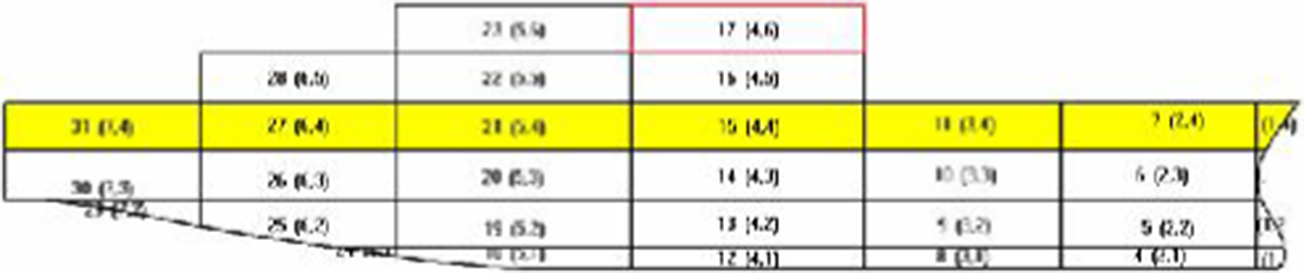
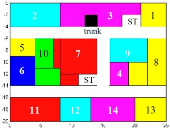
A range of layout optimization tools are seen in the literature, with the main focus on military vessels and yachts, which face different design objectives. The original Intelligent Ship Arrangement was developed for naval applications, changing weapon bays to cabins to allow publication. This produces layouts that focus more on the ergonomics of the design and on ensuring that cabins with similar utility are placed closely to each other (Daniels and Parsons, Reference Daniels and Parsons2008) at the potential detriment to other objectives, as it is not the purpose of the approach. The representation relies on a high number of constraints to reduce the design space with a number of different representations compared; this ranges up to 521 constraints in the database. It relies on the use of a binary representation where the compartment is either full or empty. The inside of the vessel is split into rectangles, with each block assigned an available compartment type. The outputs from the optimization are judged to be valid and to provide high-quality designs; however, Figures 2 and 3 show that while this helps provide ergonomic designs, the focus of these larger shipping problems, it does not provide the necessary visualization or detail to be used in a yacht optimization. In addition, the cabin size is not adapted, and there are no checks to ensure that all the necessary furniture and equipment can fit inside or whether space is wasted.
Inboard profile for 17 zone-deck test ship (Parsons et al., Reference Parsons, Chung, Nick, Daniels, Liu and Patel2008).
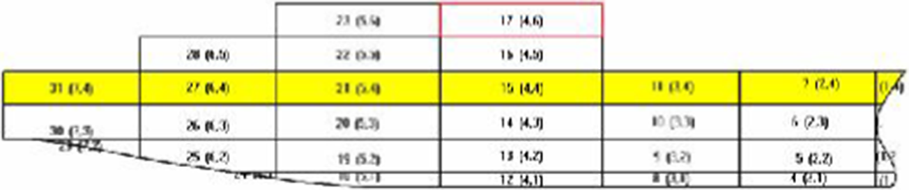
Figure 2. Long description
The diagram is a horizontal deck plan divided into three main layers, each containing rectangular zones labeled with numbers and values in parentheses. The topmost layer contains zones 23 (5.4), 17 (4.6), 28 (5.0), and 22 (5.0), with zones 23 and 17 outlined in red. The middle layer is highlighted in yellow and includes zones 31 (5.4), 27 (5.4), 21 (5.4), 15 (4.4), 11 (3.4), and 7 (2.4), arranged from left to right. The bottom layer contains zones 30 (5.3), 26 (5.2), 25 (5.2), 20 (5.3), 19 (5.3), 14 (4.3), 13 (4.2), 10 (3.3), 6 (2.3), 5 (2.2), and 4 (2.0), with values decreasing from left to right. The hull outline is visible below the lowest layer, and the plan emphasizes the spatial distribution and grouping of the numbered zones.
Final deck geometry (Parsons et al., Reference Parsons, Chung, Nick, Daniels, Liu and Patel2008).
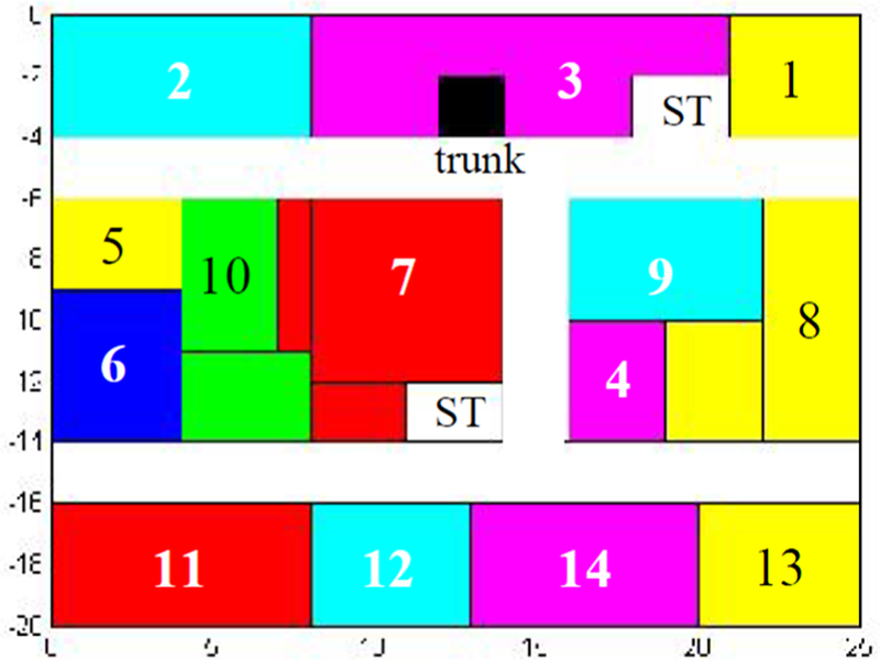
Figure 3. Long description
Starting at the top row, from left to right: a large cyan rectangle labeled 2, a magenta rectangle labeled 3, a small black square labeled trunk, a white rectangle labeled S T, and a yellow rectangle labeled 1. The second row, from left: a yellow rectangle labeled 5, a green rectangle labeled 10, a large red rectangle labeled 7, a white rectangle labeled S T, a cyan rectangle labeled 9, a magenta rectangle labeled 4, and a yellow rectangle labeled 8. The third row, from left: a blue rectangle labeled 6, a green rectangle, a red rectangle labeled 7, a white rectangle labeled S T, a cyan rectangle labeled 9, a magenta rectangle labeled 4, and a yellow rectangle labeled 8. The bottom row, from left: a large red rectangle labeled 11, a cyan rectangle labeled 12, a magenta rectangle labeled 14, and a yellow rectangle labeled 13. All rectangles are arranged in a grid with varying sizes and colors, each labeled with a number or S T, and the trunk is centrally located in the upper section.
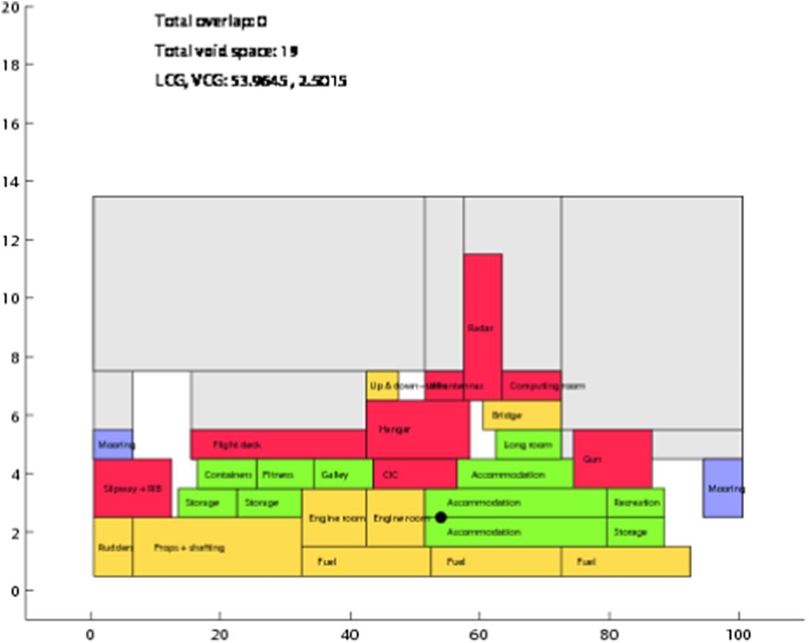
The packing approach has many similarities to the Intelligent Ship Arrangement tool (van Oers et al., Reference van Oers, Stapersma and Hopman2009), focusing on the placement of the cabins with the optimal results shown in Figure 4. It allows more flexibility than the Intelligent Ship Arrangement with different shapes of cabins, but as seen, this results in a design where there are still a number of gaps and the feasible designs show a void space of 19–69. The layout is represented using a block approach that has a relatively low number of variables for each compartment, making it scalable for larger applications. The aim is to reduce the quantity of overlaps to make the algorithm more efficient.
Feasible concept design with the least overlap in space (van Oers et al., Reference van Oers, Stapersma and Hopman2009).
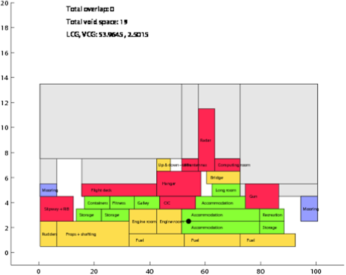
Figure 4. Long description
The diagram is a rectangular block layout with labeled compartments, each color-coded by function. The x-axis ranges from 0 to 100 and the y-axis from 0 to 20. At the bottom layer, from left to right: Rudder, Props plus shafting, Storage, Engine room, Engine room, Fuel, Fuel, Fuel, Storage, Recreation, Accommodation, Accommodation, Storage, and Mooring. Above this, compartments include Stepway plus RB, Flight deck, Containers, Fitness, Galley, C I C, Hanger, Up and down, Radar, Bridge, Long room, Computing room, Gun, and Mooring. The central compartments are color-coded: yellow for technical spaces (e.g., Fuel, Engine room), green for accommodation and recreation, red for operational spaces (e.g., Radar, Hanger, C I C), and blue for mooring. Large gray voids occupy the upper half, indicating unused space. The top left text states: Total overlap 0, Total void space 19, L C G, V C G: 53.9645, 2.5015. All compartments are non-overlapping and efficiently packed to minimize voids.
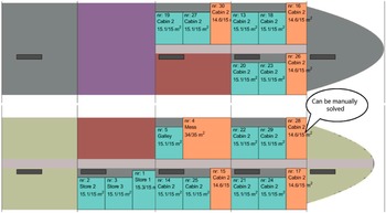
The designs contain a large number of voids, but the designs are judged to be feasible for the application and need some additional human input before it can be taken to detailed design. Integrating human input was explored by Duchateau (Reference Duchateau2016), who utilize an approach of turning off individual criteria and providing the Pareto Sets visually to understand how this changes the design space. This approach is used as part of WARship GEneral ARrangement by le Poole et al. (Reference le Poole, Duchateau, van Oers, Hopman and Kana2022), which allows the design of warships within minutes from a functional arrangement, space list, and information about the staircase options. An example of the outcome is shown in Figure 5 for the upper two decks.
Case study layout from WARship GEneral ARrangement, showing the upper two decks of the best-performing layout.
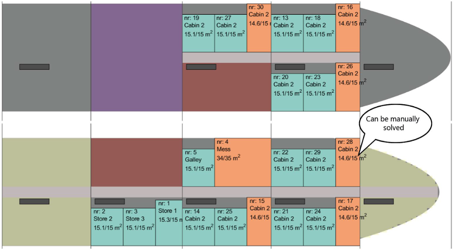
Figure 5. Long description
The diagram is a color-coded plan view of two adjacent ship decks, each divided into rectangular compartments. Starting at the top deck, from left to right: the leftmost zone is unlabelled and shaded grey, followed by a purple zone, then a central brown zone. The right half contains labeled cabins: nr 19 Cabin 2 (15.1/15 m super 2), nr 30 Cabin 2 (14.6/15), nr 13 Cabin 2 (15.1/15), nr 18 Cabin 2 (15.1/15), nr 16 Cabin 2 (14.6/15), nr 20 Cabin 2 (15.1/15), nr 23 Cabin 2 (15.1/15), and nr 26 Cabin 2 (14.6/15). The lower deck, from left to right: grey zone, then nr 2 Store 2 (15.1/15), nr 3 Store 3 (15.1/15), nr 1 Store 1 (15.3/15), nr 14 Cabin 2 (15.1/15), nr 5 Galley (15.1/15), nr 4 Mess (34/35), nr 22 Cabin 2 (15.1/15), nr 29 Cabin 2 (15.1/15), nr 28 Cabin 2 (14.6/15), nr 21 Cabin 2 (15.1/15), nr 24 Cabin 2 (15.1/15), nr 15 Cabin 2 (15.1/15), and nr 17 Cabin 2 (14.6/15). A speech bubble near nr 28 Cabin 2 states ‘Can be manually solved.’ Compartments are color-coded: orange for mess and galley, teal for cabins and stores, grey for unlabelled spaces. The bow and stern are shaded, and the plan is notated with precise room areas in square meters.
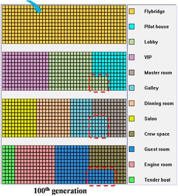
Grid-based systems have also been used to represent the layout (Nam et al., Reference Nam, Kim and Lee2010), which was extended in Nam and Le (Reference Nam and Le2012) with a four-deck optimization of the superyacht shown in Figure 6. The genetic algorithm used is a constraint-based genetic algorithm. The problem is treated as being similar to the scheduling problems seen in the optimization literature. The algorithm seeks to determine a layout with cabins while also looking at the position of the stairs. The results of the algorithm are simple layouts, with no unused space, that provide short distances for escape via the staircases. However, there is no accounting for furniture within the space or for the curvature of the hull. This approach is updated for use in Louvros et al. (Reference Louvros, Boulougouris, Coraddu, Vassalos and Theotokatos2022) with a novel encoding method and used to design a cruise ship in an academic study where the grid is transferred to a more realistic hull form.
Grid representation used for a multideck optimization considering area requirements (Nam and Le, Reference Nam and Le2012).
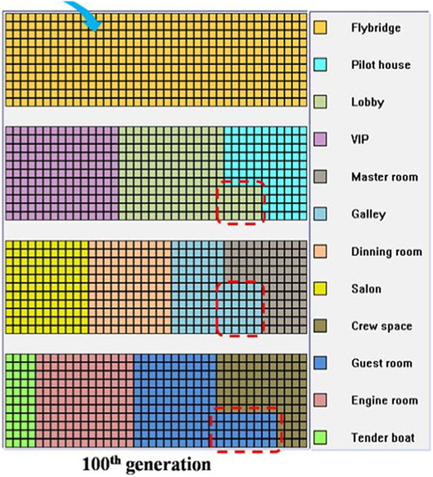
Figure 6. Long description
Starting from the top, the first deck is entirely yellow, representing the Flybridge. The second deck is divided into three sections: left is purple for VIP, center is light green for Lobby, and right is cyan for Pilot house. A red dashed box highlights a section in the center. The third deck, from left to right, is yellow for Salon, peach for Dining room, cyan for Galley, and gray for Master room, with a red dashed box around the cyan Galley area. The fourth deck, from left to right, is light green for Crew space, pink for Engine room, blue for Guest room, and olive for Tender boat, with a red dashed box around the blue Guest room. The legend at the right matches each color to its corresponding space.
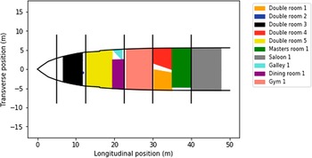
Finally, a vector-based approach to the optimization is utilized for yacht design shown in Figure 7, where the design does not fully utilize the space but generates a relatively realistic layout. This approach is in 2.5D, using a series of planar decks with interrelationships, and utilizes a large number of variables to represent each cabin but reduces the number of constraints, allowing more complex designs to be generated. The approach also integrates bulkheads, large structural elements over which cabins rarely overlap, into the design. The problem uses 49 variables to define a problem for a 24-m yacht, with two objectives of space utilization and three constraints. However, the approach breaks down on larger vessels, with the designs being a considerable distance from those that could be used in a detailed design phase and no consideration of the furniture.
Vector-based design for a 50-m yacht.
Note: Black lines demonstrate the position of the bulkheads.
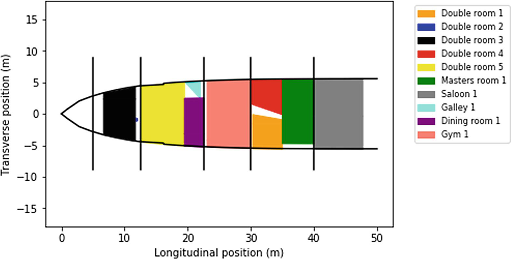
Figure 7. Long description
Starting at the bow, the first compartment is black for Double room 3, followed by yellow for Double room 1, then purple for Dining room 1. Next is a small blue section for Double room 2, a cyan wedge for Galley 1, and orange for Double room 5. Red marks Double room 4, with a white wedge for Gym 1. Green follows for Masters room 1, and the sternmost section is gray for Saloon 1. Each compartment is separated by thick vertical black bulkhead lines. The yacht outline is plotted on a grid with longitudinal position in meters on the x axis from 0 to 50 and transverse position in meters on the y axis from minus 15 to plus 15. The legend at the upper right matches each color to its room label.
The literature shows that the methods rely on a high number of constraints, which results in design spaces that are traditionally harder for genetic algorithms to solve. In addition, some of the methods show an escalation of variables with the number of compartments, also increasing the difficulty of the optimization problem. Some of these approaches have been adopted within their originating organizations (MacKenna, Reference MacKenna2012; van Oers et al., Reference van Oers, Takken, Duchateau, Zandstra, Cieraad and van den Broek2018), but these approaches have struggled to find adoption more widely through the industry. In addition, the images look generic, and they focus on a utilization of space but do not give an idea of how the design follows the brand of a specific company or how that would be possible.
3. Generating a layout optimization fitting to brand
3.1. Layout model
Drawing the layout of a motor yacht is by nature a multivariate, multiobjective task in which engineering, ergonomic, and aesthetics play a key role. The interior of the boat is constrained by the hull shape, which may vary significantly throughout the project, having an effect on which and where cabins and facilities can fit. In addition, the layout and structural design have an intercoupled relationship, where both subsystems affect each other simultaneously in 3D space. Modeling these interactions is therefore the key to achieving a global optimization; it is therefore crucial to accurately characterize the geometry of cabins and furniture, as well as the various objects they interact with, such as the hull or structural members. Here, a 2.5D vector approach has been adopted (Sobey et al., Reference Sobey, Blanchard, rudniewski and Savasta2019), updated so that cabins can lie at various heights along the hull. In addition, furniture and brand identity are incorporated through new objectives and defining variables hierarchically, improving the output accuracy and reducing complexity compared with alternative approaches that rely on large numbers of user-defined constraints. These meet industry expectation, particularly that the designs produced have a similar feel to currently available vessels, as judged by members of the design team accepting that the designs meet the corporate brand.
3.1.1. Hull geometry
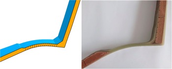
In analogy to the manual design process, the layout exploration phase starts with a hull geometry. For practical purposes, the hull is presented to the software as computer-aided design (CAD) geometry. This geometry is designed by the naval architects and represents the outer surfaces of the hull, but it does not represent the actual interior volume available as these surfaces have thickness. The inner face of the surfaces is referred to as the inner skin and is designed by structural engineers. The thicknesses depend on the various types of composite laminates used in different locations throughout the hull, normally a single skin laminate, typically at the chine, as shown in Figure 8, or a sandwich laminate, typically bottom or topsides panels (Sharp change in angle in the cross section of a hull.; Above the waterline.). The result is a complex geometry representing the variation of the available internal volume throughout the hull.
Monolithic chine section—output CAD model (left) with monolithic region hatched and built GRP structure (right).
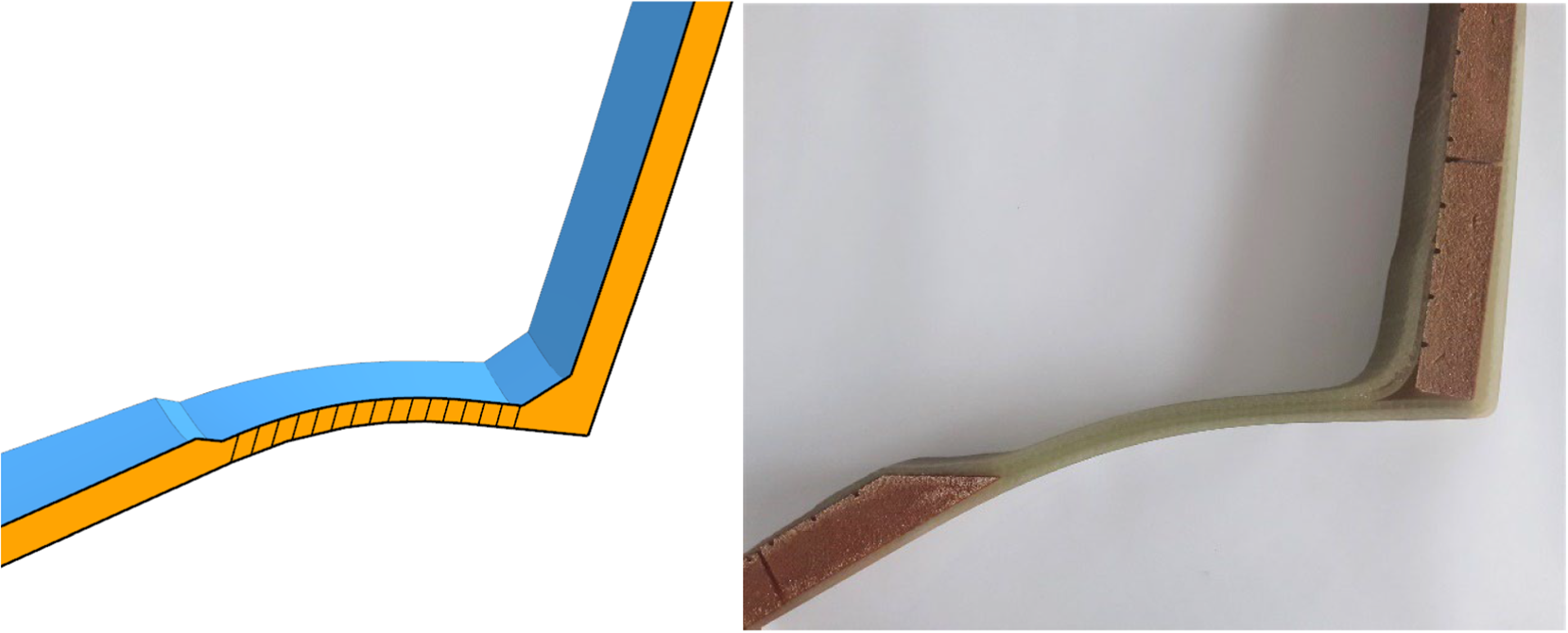
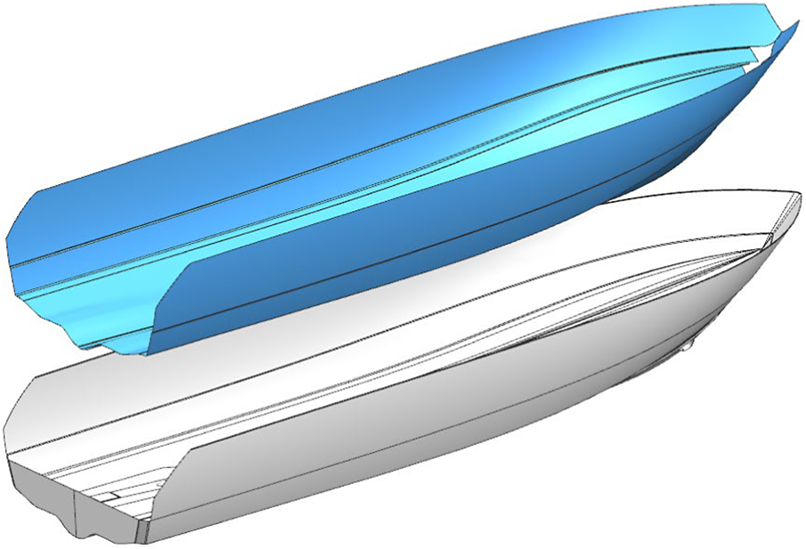
At the initial stages of the project, the hull structural scheme is not yet defined, and designers have to use a generic hull 2D offset to account for the inner skin. An inaccurate representation of the available space used at the start of the layout exploration may result in some feasible options being omitted or others being too optimistic and having to be discarded later in the process. To overcome this, an accurate representation of the inner skin offsets has been automated. This relies on structural engineers giving a range of possible laminates for various hull regions. For each layout, a selector variable is used to generate a hull laminate configuration out of all possible combinations. Program routines extract points from the input outer hull geometry, offset them, and compute transition surfaces between various thicknesses, and then export them back in the CAD package, as seen in Figure 9.
Automatically generated inner skin (blue) and outer hull skin (white).
3.1.2. Cabins
Cabins are represented as 3D geometries. The representation enables the 3D interactions of the layout to be solved with the structure in addition to optimizing the cabin heights within the given hull shape, significantly improving the overall practicality of the optimized layouts. In addition, taking into account the flare of the hull provides a realistic representation of the space available for the placement of furniture, as this is often used by the designer to maximize the cabin floor area by placing furniture as far outboard as possible (Flare indicates the angle at which a ship’s hull points outward from the vertical plane as the height increases; a flared hull will give a larger deck area than the area at the waterline.). Six variables are defined for each cabin to ensure a wide search and maximizing the diversity of solutions:
-
• longitudinal position,
-
• transverse position,
-
• length,
-
• width,
-
• floor height, and
-
• position of coupled rooms, for example, en-suite/bedroom or galley/dining.
Certain features are constrained, depending on the cabin type to ensure the outputted layouts respect the hierarchical proportions between the different cabins/facilities. For instance, guest’s cabins must be bigger than those intended for the crew. The adjustment of these features is a big part in ensuring that the design meets the brand constraints from the company, but it can be difficult to develop because they cannot always be clearly articulated. There is an element of design and improvement in the generation of these constraints, balancing computational efficiency, credibility of the design, and innovation.
Removing any unused space in the deck was a key focus in previous iterations of the design tool (Sobey et al., Reference Sobey, Grudniewski and Savasta2019) and was used as one of the objectives. Here, due to the increased complexity of the problem due to the 3D features and the level of details taken into account, a more effective approach is adopted. A variable defines the placement order in which cabins are placed forward to aft along the hull. Their length is initialized by a variable; however, once all cabins are placed, the wasted space between accommodation bulkheads is calculated, and cabin lengths are automatically adjusted to fill 100% of the available space. How much variation is allowed for each cabin is driven by the cabin type and position. This removal of the “wasted space” considerably improves the efficiency of the optimization as fewer iterations are needed to reach the state where all available space is used, and therefore the objectives can be focused on “how” the space is used.
3.1.3. Staircases and corridors
Staircase position and design are critical elements when drawing a motor yacht layout and are often key features in making a general arrangement work efficiently; it is, therefore, essential to consider them during the exploration process. In this model, staircases are allowed to be placed both longitudinally and transversely. A staircase angle is assumed to calculate the staircase footprint length. Transverse staircases are free to sit between cabins on either side of the boat, and longitudinal stairs are placed freely aiming to maximize the number of cabins accessible from the landing lobby, minimizing corridor spaces. To avoid infeasible arrangements, the following placement constraints are applied:
-
• Transverse staircases should not be placed where the staircase length exceeds the width of the main deck.
-
• If the helm is located on the main deck, no staircase can be placed forward of the helm screen.
-
• Access for groupings of specific cabin/facility types, for example, crew areas and guests, must be accessed by separate staircases.
Since staircases are only placed between cabins, there is a finite number of possible locations; therefore, once cabins are placed, a combinatorial search algorithm will find all possible longitudinal and transverse staircase arrangements respecting those constraints, and an optimization variable will be used to select a single one. This way, all arrangement can be explored, and the optimization will naturally converge toward the better suited one for each cabin arrangement.
The next step is to place corridors. The criteria for a cabin to be deemed accessible is having a bulkhead adjacent to a lobby or corridor surface that extends for a certain length that corresponds to the minimum allowable distance to fit a door. Once staircases and corresponding lobby surfaces are placed, cabins without access are identified, and corridors are added to bridge them to the closest staircase/lobby. A higher fitness is given to corridor paths that are straight lines, but they can be divided into various transverse offset segments when required; for example, if a transverse cabin along the path requires a larger width than the one on the opposite side.
3.2. Furniture placement
Furniture placement is a core criterion to assess whether a yacht layout is feasible. The geometry of the cabin and the 3D interactions with the hull, structure, and headroom are key properties in choosing a viable furniture placement. Subjectivity plays a major role as well; for a given set of cabin properties, different designers or customers are likely to have different preferences. However, this subjectivity comes mainly when the design space is big enough to allow for various feasible/practical solutions; in smaller constrained spaces, it is often challenging to find a single working arrangement. The present model optimizes the furniture placement to find the “best” arrangement since that would involve defining a specific style or design philosophy that would impede the creativity of the interior designers or the preferences of the customer. Instead, the furniture placement is used to assess the feasibility of the cabin geometry by ensuring that at least one furniture arrangement is possible and assessing its practicality.
The placement and assessment of the furniture are achieved via a sub-optimization routine using an evolutionary algorithm of which the objective functions encompass a variety of features capturing the placement practicality of each piece of furniture. The metrics include the following:
-
• proximity to other pieces of furniture,
-
• proximity to access point/door,
-
• visibility from access point/door,
-
• headroom available,
-
• proximity to corner,
-
• position to cabin center of area,
-
• transverse position, and
-
• orientation angle.
Each type of furniture has a specific weight associated with those different metrics. For example, when entering a bathroom, the sink/mirror should have a high weight for visibility, contrastingly the toilet that should be pushed away from that visibility field. Each item of furniture has a placement value given in the following equation:
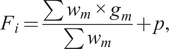
where
$ {g}_m $
 is the assessing function for metric m and
$ {w}_m $
is the assessing function for metric m and
$ {w}_m $
 is the associated item weight ranging from 0 to 1 for metric m. P corresponds to the penalty added due to two extra metrics that ensure that the items do not overlap and that they are fully included within their respective cabin bounds.
3.3. Objective functions
Two objectives are set, and no constraints are used for this optimization. The first objective is used to capture the interior practicality of the layout using the cumulated placement value of each item within each cabin given by the following equation:
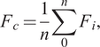
where n is the number of items of furniture in the cabin and
$ {F}_i $
 is the item placement value, as described in Equation (1). The overall layout value is given by the following equation:
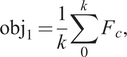
where k in the number of cabins and
$ {F}_c $
 is the fitness value of the cabin given in Equation (
$ 2 $
is the fitness value of the cabin given in Equation (
$ 2 $
 ). The nature of this objective prioritizes large cabin areas to ensure plenty of furniture arrangements are possible. One of the ways this can be achieved is by raising the floor of the cabins since the hulls are usually narrower at the bottom and wider at the top. Increasing the floor height will be beneficial for maximizing interior space as well as allowing more bilge space for structural members and services (The part of the hull that would rest on the ground if it was unsupported by water.). However, this will increase the overall height of the boat, which is not desired as it negatively affects the weight of the boat and raises its vertical center of gravity resulting in poor stability and seakeeping performance. In addition, an unnecessarily tall boat will affect the proportions of the exterior design, where lower and slender designs are preferred to increase the perceived length, which results in a sleeker allure.
A second objective is therefore required to balance this effect by rewarding a lower and more even floor height. For each cabin, the vertical bounds are defined, (
$ {h}_{\mathrm{min}},{h}_{\mathrm{max}}) $
 between which the cabin floor can be placed. This is derived from the headroom available and the allowable structural clearance at its position. The first term of the objective, actual height,
$ {h}_{act}, $
between which the cabin floor can be placed. This is derived from the headroom available and the allowable structural clearance at its position. The first term of the objective, actual height,
$ {h}_{act}, $
 rewards a floor height for each cabin that is closer to its minimum bound. For each group of cabins accessed by the same access route, their heights should be at the same level. Therefore, the second term is aimed at reducing the number of step changes throughout the layout, as it would be easy for the algorithm to find solutions where all cabins are set at vastly different heights, but it would not be practical. This is performed by minimizing the standard deviation
$ {\sigma}_{h_j} $
rewards a floor height for each cabin that is closer to its minimum bound. For each group of cabins accessed by the same access route, their heights should be at the same level. Therefore, the second term is aimed at reducing the number of step changes throughout the layout, as it would be easy for the algorithm to find solutions where all cabins are set at vastly different heights, but it would not be practical. This is performed by minimizing the standard deviation
$ {\sigma}_{h_j} $
 of the cabin floor heights within the cabin group sharing this access route. The second objective function is described in the following equation:

where k in the number of cabins and j is the number of access groups.
4. Integration within the design process
Designers, naval architects, and structural engineers all work on their respective subsystem at the start of a new project. After the initial reviews, one or more subsystems will need to be reworked and reevaluated to match the requirements of the other subsystems as the team iterate to a final design. For example, a hull shape adjustment driven by performance will affect the internal volume and therefore the layout. The subsystems develop at different rates, for example, the hull shape is likely to be driven by the results obtained by Computational Fluid Dynamics (CFD) analysis, which might take days, whereas the development of the layout might span many weeks. This means that the initial stages subsequent to the project kick off are usually globally suboptimal as decisions are often taken with limited information, although individual subsystems still run efficiently. Therefore, with the difficulties in reaching a design that satisfies the design constraints, it is typical that a limited time is dedicated to exploring all design possibilities.
The aim of the presented tool is to assist the decision-making process at this critical initial stage by rapidly providing insight into the design direction that will best suit a given customer requirement. It provides a metric around the feasibility of the hull and requirements for the interior layout, without having to commit excessive resource and time.
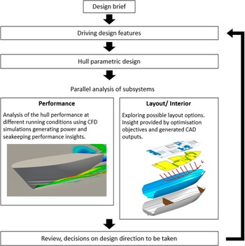
Figure 10 illustrates how the tool is integrated into the current design process. The optimization takes place at the concept stage of the project after the initial dimensioning of the hull and the definition of key parameters, such as collision and engine room bulkhead (An upright wall that separates compartments for structural stiffness and to stop water flows in damage, potentially also stopping other hazards.). Initially, a design brief is gathered by talking to the customer and distilled to key design features. The information required to use the tool should be minimal to ensure the designs are not over constrained and all the inputs can be extracted directly from the design brief. The design features are dependent on the vessel type but for a superyacht will consider the key profile lines, restricting the max allowable height of the yacht or affecting the slenderness of the hull, the hull shape, depending on the primary use of the vessel, and the layout requirements, such as the number of cabins, crew compartments, galley or crew mess, and whether the main deck is open of closed. These are included for each case study as the hull form and layout requirements. The structural engineers also provide the variables for thickness for hull and topside panels and a frame spacing range, typically 750–1,200 mm for Glass Reinforced Polymer (GRP) motor yachts in this study. The bounds of allowable values of these variables can be tuned based on vessel type, size, and level of flexibility/exploration available for the project. This approach ensures that basic structural aspects are considered simultaneously with the layout during the exploration process. Alternatively, if no or limited structural exploration is required or wanted, these variables can be locked as constants, and a series of layout explorations can be run with several discrete values.
Process integration of the tool within the design office.
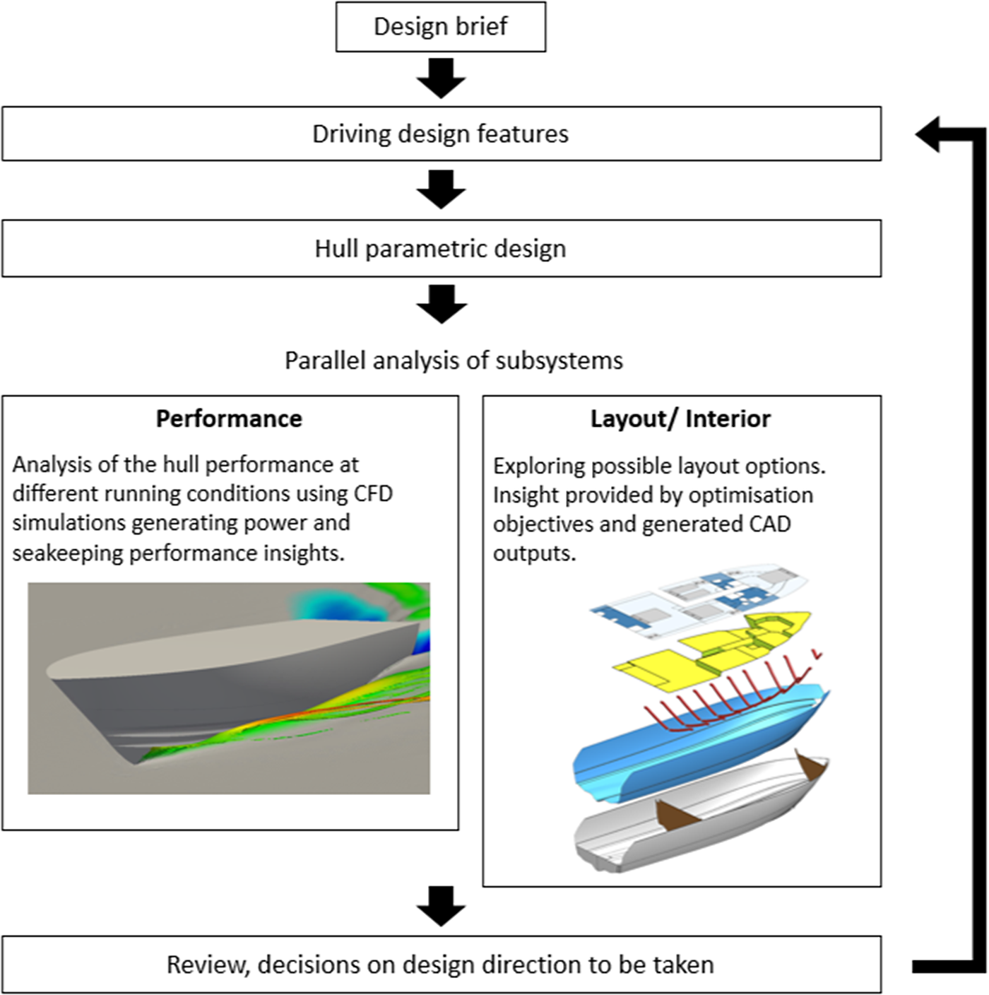
Figure 10. Long description
At the top is a box labeled Design brief, followed by a downward arrow to Driving design features, then Hull parametric design. Another arrow leads to Parallel analysis of subsystems, which splits into two side-by-side boxes. The left box, Performance, contains text describing hull performance analysis using C F D simulations and includes a rendered hull image with colored flow lines. The right box, Layout/Interior, discusses layout options, optimization objectives, and C A D outputs, with a diagram showing exploded views of hull and interior components. Both boxes are enclosed and aligned horizontally. Below, arrows converge to Review, decisions on design direction to be taken. A thick arrow loops from the review box back to the Driving design features box, indicating iteration.
The fundamental aspect of a successful integration within the design house lies in the practical use of the outputs. This output needs to be in a format that maximize the amount of information that can be conveyed to the designers. During the initial stages of each project, designers typically begin the layout design phase by gathering information on current market trends and sharing initial conceptual ideas. It has been found, using trial and improvement with the design team, that presenting output layouts from the tool during this phase is most effective. Depending on the project size and the size of the design space, three to six options are shown, which provides inspirations and alternative perspectives when no design directions was specified yet. In addition, this approach allows designers to begin work directly on options with a higher degree of confidence in their practicality.
In addition, the 3D interactions are crucial to the feasibility of a layout and therefore are the key aspects that designers would look out for when analyzing an option. These 3D aspects are hard to fully encapsulate with only 2D drawings and annotations; therefore, routines were developed to automate the generation of 3D surfaces in CAD software that designers are familiar with, here Siemens NX. This enables designers to have a deeper insight into the layout geometries at an earlier stage than what they would usually do with the manual process since 3D modeling tends to start later in the development due to its laborious nature. This gives designers a higher level of flexibility, which enhances their capacity to detect potential areas of improvement and rapidly make amendments without having to reuse the tool. It should be noted that the generated 3D surfaces are only meant to act at a platform to analyze the layout options and only take into account the level of details considered during the optimization; hence, further detail stages of the design will require more advanced 3D development.
5. Generalization of implicit brand constraints
A series of case studies are performed to investigate the performance and limitations of the developed approach. The 16-m planning hull, 25-m semi-displacement hull, and the 30-m motor yacht hull designs are compared with those developed by designers previously. The 16-m planning hull is a common case where a layout has to fit within a small internal volume leading the cabins geometry to become more complex to find an optimum solution. The semi-displacement hull represents a challenging design situation due to the rapid change in shape of the hull. The 30-m motor yacht allows the comparison of an A and a B hull to demonstrate different challenges for the search algorithm. These three case studies represent the typical size of design generated within the Olesinski design studio. A longer yacht of 118 m is also designed, representing a custom superyacht design; this is longer than that produced in the design studio, and so there is no comparative real-world design but illustrates the difference in the design problem.
5.1. Sixteen-meter motor yacht
The first study was carried out on a 16-m motor yacht, a common size within the market; the hull is presented in Figure 11. This hull is designed primarily for performance, not internal volume, which constrains the possible layouts.
Hull form of the 16-m planning yacht.

The layout requirements were set as the following:
-
• six sleeping spaces with at least two double bed cabins,
-
• two to three bathrooms with at least one double bed cabin having an en-suite, and
-
• one main access route from main deck route not to be forward of 25% LOA aft of the Forward Perpendicular (FP).
The output layouts generated by the tool are shown in Figure 12. It can be seen that layout b is essentially a mirror image of layout a with one difference being that while layout a only has a single bed in the mid cabin, layout b has a twin bed; however, it can be seen that the space is tight and passage, although the cabin is likely to be difficult. Layout c offers a different perspective by placing the aft cabin bathroom further aft. This allows the staircase to be offset transversely, therefore freeing some space for the mid cabin, allowing a twin bed to fit more comfortably. The design direction of layout c is similar to the one chosen by the designers in layout d. It can be noted the human layout displays a more efficient use of space especially in tight areas such as the bathroom. For example, a second door can be fitted in the most forward bathroom providing direct access from the corridor.
Output layouts for the 16-m planning hull (a–c), compared with the designer’s layout (d).
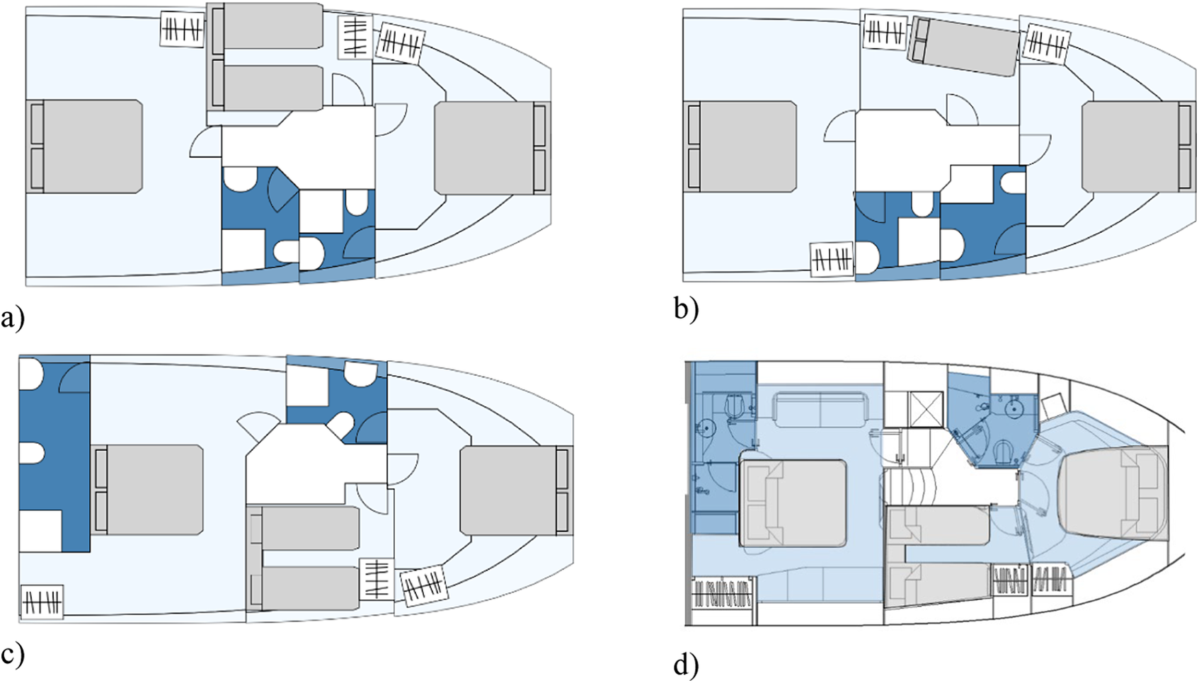
Figure 12. Long description
Panel a at top left shows a boat plan with two large cabins at bow and stern, a central section with two blue-shaded bathrooms and a corridor, and staircases at both ends. Panel b at top right displays a similar plan but with the bathrooms and corridor slightly shifted, and the stern cabin rotated. Panel c at bottom left presents a layout with the stern cabin moved to the port side, the central corridor and bathrooms rearranged, and the bow cabin unchanged. Panel d at bottom right depicts the designer’s layout, with detailed furniture, fixtures, and appliances visible, including a lounge area at stern, two bathrooms, a galley, and a forward cabin, with more intricate spatial divisions and fittings than the other panels.
5.2. Twenty-five-meter semi-displacement hull
The layout for a semi-displacement hull of 25-m length overall (LOA) is designed; this features a round bilge as seen in Figure 13. The aim of this case study is to assess the feasibility of the tool on hulls where the discontinuity is non-existent, or at least smoothed by having a round bilge instead of a chine. On planning hulls, the hard chine acts as a point of reference at which the gains of placing a cabin, making the optimization choice obvious. The advantages of placing the floor any higher are minimal as the sides are almost vertical, and the increase in floor area is minimal compared with the increase in overall boat height. This clear discontinuity at the hard chine is used as a metric by the tool to define the minimum height for maximum area gain at which the cabin could be placed, at its specific longitudinal position. This is not possible on the round bilge.
Hull form of the 25-m semi-displacement yacht.

The layout requirements were set to be as standard for a high-volume production yacht as follows:
-
• six to eight sleeping spaces for guests with all cabins with en-suites,
-
• two crew cabin forward OR aft of the guest areas,
-
• crew area must have at least one bathroom and optional one sitting/dinette space, and
-
• crew and guest to have separate access routes up to main deck.
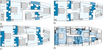
The results of the optimization are shown in Figure 14, with the layouts b and c showing a strong similarity with the original design generated by the design team. The main difference is around the position of the twin beds, with c using the same orientation as the designers, and b selecting it to be placed on the other side. The position of the crew cabins is also a little different, with the tool selecting a symmetric layout at the forward most point on the hull and the heads just behind (Bathrooms.). While the designers select a single cabin at the forward most point, the other cabin opposite the head just behind. Layout a has a considerably different design perspective, with the crew cabins selected to be at the aft of the vessel and a move to bring one of the guest cabins forward. This allows the designers to consider this as an alternative design and the benefits it might bring. This hull design shows a human equivalent set of designs while also showing that there are other available layout options.
Output layouts for the 25-m semi-displacement hull (a–c), compared with the designer’s layout (d).
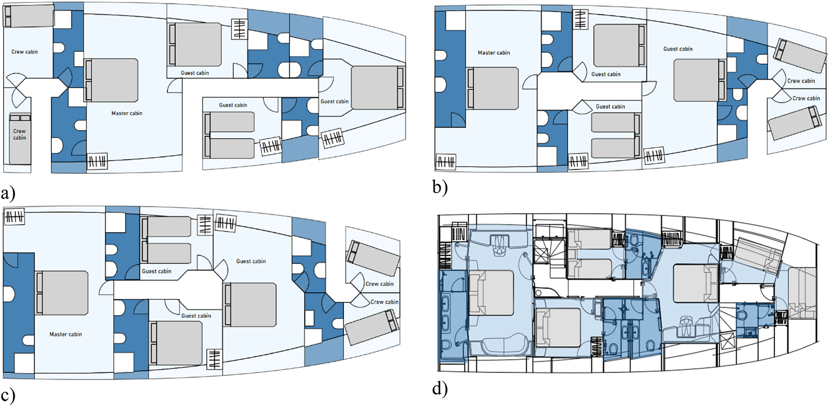
Figure 14. Long description
Panel a, at the top left, shows a deck plan with a crew cabin at the stern, followed by a master cabin, two guest cabins amidships, and a crew cabin at the bow. Blue shaded areas indicate service or utility spaces adjacent to cabins. Panel b, at the top right, arranges the master cabin at the stern, two guest cabins amidships, and two crew cabins at the bow, with blue service areas distributed similarly. Panel c, at the bottom left, places the master cabin at the stern, two guest cabins amidships, and two crew cabins at the bow, with minor differences in the shape and position of blue service areas compared to panels a and b. Panel d, at the bottom right, presents the designer’s layout with more detailed interior features, including furniture and fixtures within each labeled space. The master cabin is at the stern, two guest cabins amidships, and two crew cabins at the bow, with blue service areas and additional interior details such as beds, desks, and bathrooms clearly illustrated. All panels are oriented with the stern to the left and the bow to the right.
5.3. Comparison of hull types for a 30-m motor yacht
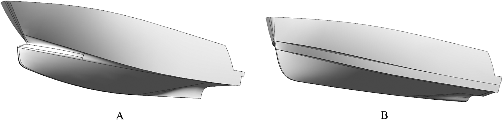
A displacement hull of 30-m LOA and 24-m length waterline is designed primarily for maximum internal volume. Here, two hulls will be designed with different features but with a matching displacement and layout requirements. Both hulls feature a chine sitting much lower, close to the waterline, to maximize topside width as far forward as possible. Hull A is designed 250 mm wider with a wave piercing bow and shallower dead rise, whereas Hull B features a more conventional bow and a dead-rise distribution but with a second chine above the waterline, as seen in Figure 15. The aim of this study is to replicate the changes in hull geometry likely to occur on the early stages of the project.
Hull A with wave piercing bow and Hull B with a more conventional design.
The layout requirements were set to be the same as for the 25-m semi-displacement hull, but where the crew cabins are constrained to be forward of the guest areas, this allows an exploration of the variation of potential designs in a more constrained setting:
-
• six to eight sleeping spaces for guests with all cabins with en-suites,
-
• two crew cabin forward of the guest areas,
-
• crew area must have at least one bathroom and optional one sitting/dinette space, and
-
• crew and guest to have separate access routes up to main deck.
The designs for Hull A are shown in Figure 16, where layouts a and b are similar to the designer’s layout, but where layout c shows some variations. In design b, the two crew cabins forward are the same, with a change in alignment of the heads for one of the crew and one of the guest cabins. The guest cabins have a similar orientation with the head of the master cabin flipped between layout b and the designer layout. Layout a follows a similar design to layout b but with a mirroring around the center of the vessel from the forward to the aft planes. This results in the forward movement of a guest cabin and closer proximity to the crew cabins, without the noise break provided by the heads in layout b, although this is not evaluated in the optimization and requires designer analysis. Layout c provides the biggest changes with the crew cabin at the forward most point and the guest cabins separated by the ensuites. This means that the master cabin has its ensuite forward of the cabin rather than at the rear. Again, the guest cabins back on to the cabin crews at one end. Overall, these designs show less variation than in the 25-m semi-displacement hull, but the designs are judged to be human equivalent.
Output layouts for the 30-m Hull A (a–c), compared with the designer’s layout (d).
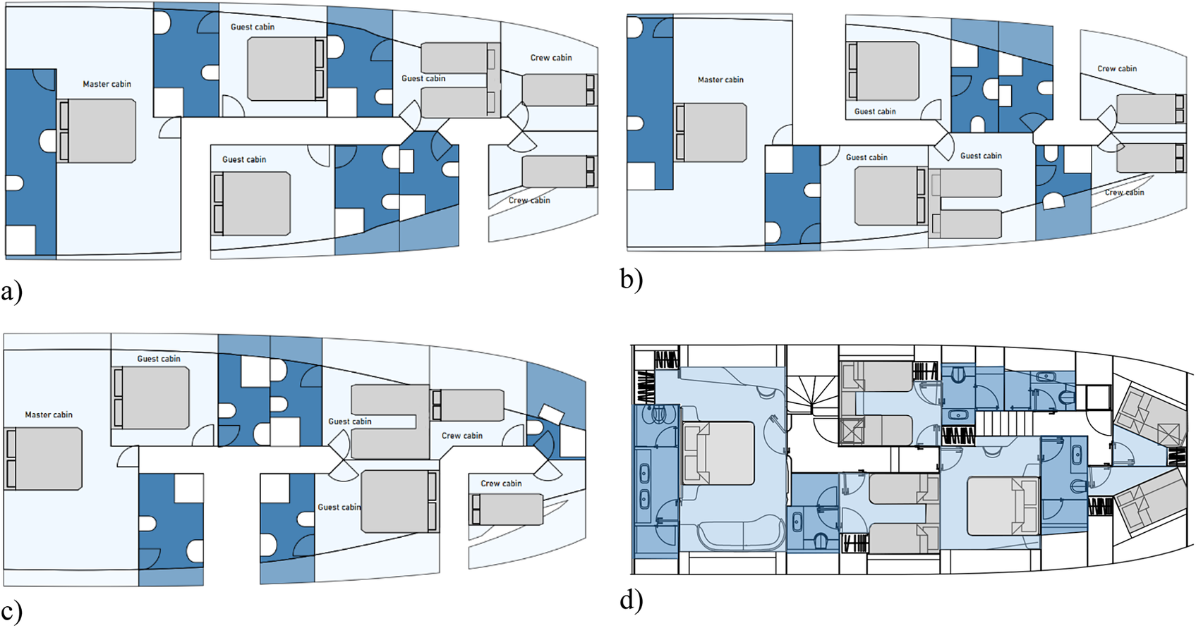
Figure 16. Long description
The diagram contains four yacht floor plans labeled a, b, c, and d, arranged in two rows and two columns. Each plan is oriented with the bow to the right and stern to the left. Panel a shows a master cabin at the stern, two guest cabins midship, and two crew cabins at the bow, with blue and white shaded areas indicating different zones. Panel b has a similar arrangement but with slight variations in the placement and size of guest and crew cabins. Panel c also features a stern master cabin, two guest cabins midship, and two crew cabins at the bow, with minor differences in room shapes and partitioning. Panel d, the designer’s layout, displays a more detailed plan with labeled master, guest, and crew cabins, additional staircases, and more intricate room divisions, including bathrooms and storage areas. All plans use blue shading to highlight specific zones, and each room is labeled for function.
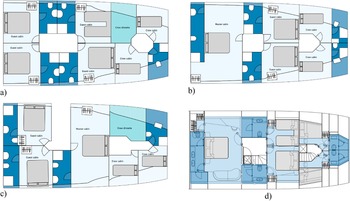
The results for Hull B are shown in Figure 17. These designs show a much larger variation than in the 25-m semi-displacement hull and hull A. In this design, then, layout b and the designer’s layout are similar with a double bed in layout b and a twin room in the designer layout that could be easily exchanged. For layout a, then, rearranging the cabins, reducing the master cabin size, and having a shared head for the crew allow for the inclusion of a crew dinette and a fourth cabin. In layout c, then, the master cabin and guest cabins are mirrored in the horizontal plane. Similarly to layout a, there is the inclusion of the crew dinette but a shared crew head. In Hull B, there is a human-equivalent design, but there are also a wider range of different layouts that can be produced, with a considerably different utility.
Output layouts for the 30-m Hull B (a–c), compared with the designer’s layout (d).
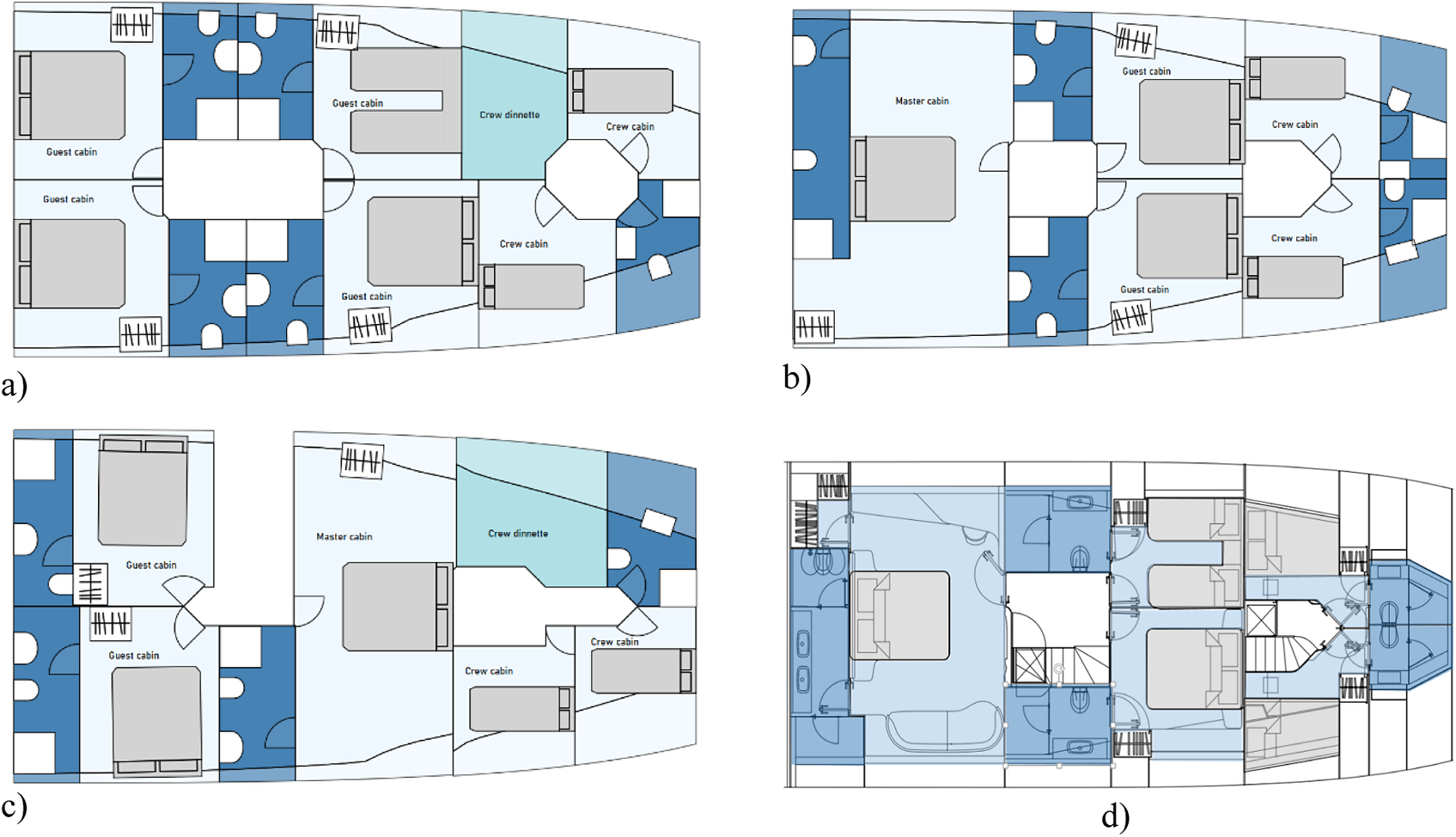
Figure 17. Long description
Panel a, top-left, shows a symmetrical arrangement with guest cabins on both sides of a central corridor, crew cabins and dinette at the bow, and labeled areas including guest cabin, crew cabin, and crew dinette. Panel b, top-right, features a master cabin on the port side, guest cabins starboard, and crew spaces forward, with a central corridor connecting all rooms. Panel c, bottom-left, has a split layout with the master cabin aft, guest cabins port, and crew areas forward, with a crew dinette adjacent to crew cabins. Panel d, bottom-right, presents the designer’s layout with detailed furniture and fixtures, including beds, tables, and stairs, overlaid on the same hull outline. All panels use consistent labeling and color-coding for functional zones.
5.4. Custom 118-m superyacht
The optimization approach is applied to sizes of boat exceeding that of the typical mass production scope, generally considered to be in the custom built superyacht range. The aim is to assess the potential of the approach when applied outside of the intended scope of the present tool. A single hull with a 118-m LOA is shown in Figure 18. Smaller furniture objects are removed as this becomes less relevant due to the size of the compartments. In these designs, there is no designer layout as this vessel is larger than the design office has considered.
Superyacht hull form with a length of 118 m.

The layout requirements were set to reflect a custom designed superyacht, with a small increase in the number of sleeping spaces for guests but an increase in the number of crew cabins, a captain’s cabin, and a larger crew area with additional utilities for the crew:
-
• 14 sleeping spaces for guests with all cabins with en-suites,
-
• 10 crew cabins forward of the guest areas,
-
• one captain’s cabin,
-
• crew area must have at least one crew mess, one laundry, and one galley, and
-
• crew and guest to have separate access routes up to main deck.
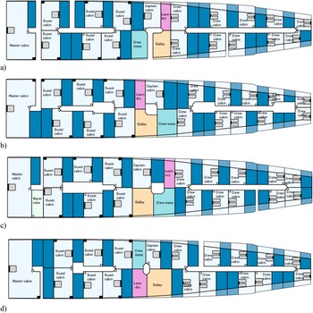
Figure 19 shows the results for the designs, which show a closer similarity in design than for the smaller vessels. This is despite having a wider variation in the number of different types of compartment that can be considered. The crew cabins are all at forward positions in the vessels in slightly different orientations. In the middle, the layouts have positioned the crew area; this provides one of the largest variation between the designs with layout a having a larger captain cabin and ensuite, layouts b and c having a larger galley and crew mess, and layout d with a larger galley and laundry at the expense of the captain’s cabin and crew mess, which provides the design with the lowest utility. At the aft of the vessels, then, layouts a, b, and d all have similar designs. However, layout c has included a wardrobe space for the master cabin. These designs show a smaller variation than the previous designs, where the size of the hull makes it easy to fit in all of the elements required.
Output layouts for the 118-m superyacht.
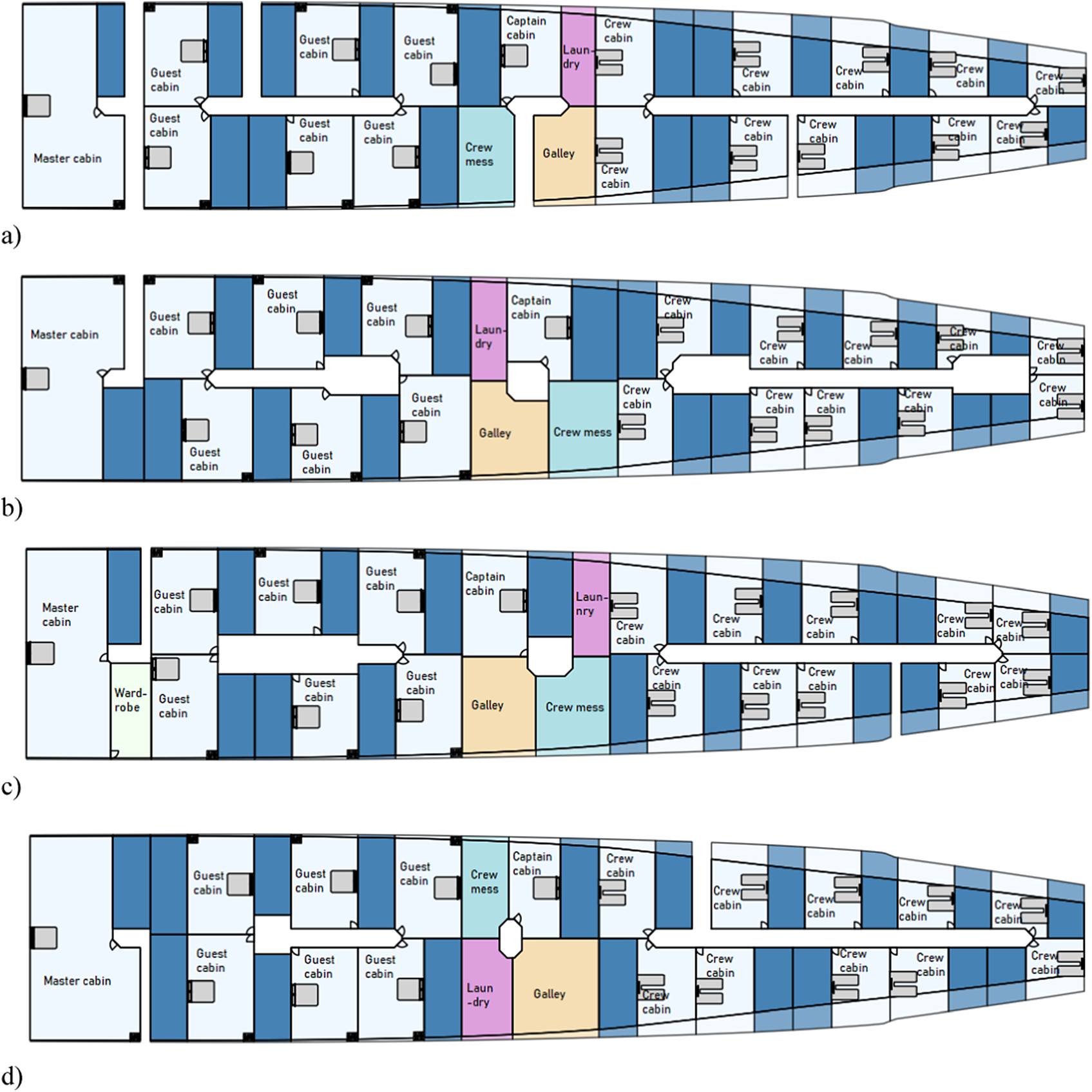
Figure 19. Long description
Panel a, topmost, displays a master cabin at the far left, followed by guest cabins in blue, a centrally located crew mess in light blue, galley in yellow, laundry in pink, captain cabin, and multiple crew cabins extending to the right. Panel b, second from top, has a similar left-to-right sequence but shifts the galley and crew mess further right, with laundry and captain cabin adjacent, and more crew cabins at the bow. Panel c, third, introduces a wardrobe next to the master cabin, with guest cabins, galley, and crew mess centrally, laundry and captain cabin to the right, and crew cabins at the far right. Panel d, bottom, arranges the master cabin at left, guest cabins, crew mess, galley, laundry, captain cabin, and crew cabins, with some crew cabins split by a corridor. Each panel uses consistent color coding: blue for guest and crew cabins, yellow for galley, pink for laundry, and light blue for crew mess. The layouts illustrate different spatial distributions and access routes for key functional areas.
6. Discussion
The tool is always capable of finding adequate cabin arrangements for a wide range of size and hull shapes, with some options that closely resemble the ones drawn by designers. All options, while being different, display similar cabin proportions and respect the industry or brand requirements defined in a brief such as the number of cabins or segregation of crew and guest areas. It can be seen that as the size of boat and the number of compartment increase, the design space gets larger and that the options become more diverse, as fitting the layout into these space becomes a simpler problem; hence, more feasible solutions are possible. For the smaller boats, there are a narrower range of options available. This is similar to what designers experience when exploring layouts possibilities, which shows that the developed approach captures the right characteristics of the design problem. However, as the size reaches that of the custom yacht case study, it was hard for designers to compare the tool output options since their evaluation criterion have changed. For these sizes, interactions between the layout and hull and structures become minor, which leave a design space where the preferred options are driven by deck ergonomics and subjective aspects, typically customer preferences. This is reflected in the literature, where those design tools (Daniels and Parsons, Reference Daniels and Parsons2008; van Oers et al., Reference van Oers, Stapersma and Hopman2009) focused on larger vessels ignore furniture and compartment sizing with a focus on ensuring groupings of compartments with similar utility.
However, much of the literature considers the layout problem to be similar to the scheduling problem; it is shown here that this is not the case as the change in length generates a different optimization problem that is distinct at different ship lengths. It indicates that the objective functions should change as the vessel length grows. Weightings and constraints must also be redesigned with changes in length of the vessel; while there are ways to quantify the design such as space utilization and size of compartments, there are elements of ergonomics and aesthetics that are difficult to define. This indicates that a focus on fewer constraints and weightings will help generate a wider range of different vessel types. In the same manner, there will need to be a period of design and iteration to generate the weightings and constraints required to fit the brand of a specific company. This implies that the layout design tools are less general than assumed in much of the literature, with the objectives and constraints being specific to the type and size of vessel for which they were designed. However, the hierarchical variables apply more generally, and there are benefits to incorporating the key furniture and fittings within the design to ensure that the cabins are fit for purpose.
Designers have found that having a range of options instead of a single one gave another perspective on what and how cabins can fit within the hull, sometimes taking ideas from the output layout as a whole or sometimes for specific areas such as the crew areas or staircase arrangements. While the furniture arrangement is not always optimum for each cabin, it was enough to prove the usability of the layout, and designers were satisfied of the arrangement found, especially in tight spaces such as the forward end of the hull.
One limitation of the tool is that manual filtering is applied between the outputs of the algorithm, before the designers see the specific designs. The filtering uses a combination of looking at where the solution lies on the pareto front (objective space) and how the high-level cabin arrangement looks like (variable space) to reduce the number of designs to the main variations, usually 3–6. This filter could be improved and automated using more advanced data analysis or classification tools on the algorithm’s data, as well as feature recognition tools on the layout images themselves. Another is the lack of interaction considered with the main deck. Even if hard points are considered, such as the front screen and aft patio door position, designers have found that furniture could be placed where headroom would in reality be limited, which for smaller boats can drastically impact where cabins are placed. To resolve these issues, a more accurate definition of the main deck is needed; however, it is unlikely to be available at this stage in the design process; hence, the main deck may need to be incorporated into the optimization process.
7. Conclusion
Yacht design is challenging, in part because of the tight constraints provided by the hull. The concept design drives the cost and performance of the vessel but is normally performed rapidly to provide time to complete the detailed design. It is therefore vital to support designers in this phase of design. A number of tools have been developed to generate concepts for various ship and boat types. However, these tools need to be accepted by the design team that will use them if they are going to be effective. This requires the vessel to meet utility requirements and to match the style of vessels previously designed by the company.
To incorporate the tool into the design team, the optimization process is simplified to having two objectives, and a hierarchical variable definition is used to derive the furniture arrangement, incorporating interior design and technical metrics weighted specifically for each furniture type, which reduces the input from the designers. This is complimented by visualizing the designs in a group of typically three to six images with their respective 3D geometries. The team uses the layout designs as guidance and reference to develop options with a high level of confidence in their feasibility.
A number of case studies are explored, generating layouts for the mass production market vessels that conform to the brand developed over the last decades. However, when the tool is used on the larger vessels, these designs are more generic, and it becomes an ergonomic issue with a different definition of success. The results illustrate that the key features are captured using this new variable definition and only two objectives and that this does not require a large number of constraints reducing designer input into the process. The result is layouts that are judged to be human-competitive by the design team.
Data availability statement
Data availability does not apply to this article as no new data were created or analyzed in this study.
Acknowledgements
The authors would like to thank Lloyd’s Register Foundation for their support and the Olesinski design team for feedback on the designs generated.
Author contribution
Conceptualization-Equal: T.S., B.E., A.S.; Data Curation-Equal: T.S.; Formal Analysis-Equal: T.S., B.E., A.S.; Investigation-Equal: T.S., B.E., A.S.; Methodology-Equal: T.S., B.E., A.S.; Visualization-Equal: T.S.; Writing—Original Draft-Equal: T.S.; Writing—Review and Editing-Equal: T.S., B.E., A.S. All authors approved the final submitted draft.
Funding statement
This work received no specific grant from any funding agency, commercial, or not-for-profit sectors.
Competing interests
The authors declare no competing interests.
Ethical standard
The research meets all ethical guidelines, including adherence to the legal requirements of the study country.








 Open access


Comments
No Comments have been published for this article.