


1. Introduction and background
Engineering designers have long understood that a component’s fexural and torsional stiffness is proportional to its second moment of area (Reference Gross, Hauger, Schro¨der, Wall and BonetGross et al., 2018). Hollow geometries that enclose interior voids distribute material away from the neutral axis, maximising second moment of area and stiffness for a given mass.1 This property is exploited by space frame designers, who favour tubes over bars due to the fexural and torsional loads applied to the members (Reference Liu, Lee, Koronaki, Pietroni and XieLiu et al., 2023). This study uses shelling as a method of hollowing solid structures and assesses the feasibility of its strategic use for structural lightweighting. Shelling serves to increase a structure’s second moment of area to mass ratio and therefore stiffness also.
Traditional structural design methods have focussed on selection from a catalogue of predetermined cross sections (such as box, round, or I) to choose a shape that balances the mass and stiffness requirements of the design (Reference Pasini, Smith and BurgessPasini et al., 2003). In recent years, the design freedom offered by Additive Manufacturing (AM) has led to increased interest in computational design approaches. This in turn has enabled further design space exploration using methods such as Topology Optimisation (TO) and Generative Design (GD), both of which have enabled signifcant improvements in structural lightweighting when compared to traditional methods (Reference Walia, Khan and BreedonWalia et al., 2021). There is a distinction between the two approaches: TO is the mathematical procedure of modifying existing geometry to meet a specifc target. Meanwhile, GD is a holistic approach that considers the manufacturing process, component use case(s)
1 A round bar with the same fexural stiffness as a standard UK scaffolding pole (which are tubes) would require 2.36x more material (Scaffolding Direct, 2024; Reference Gross, Hauger, Schro¨der, Wall and BonetGross et al., 2018).and synthesises geometry from scratch without requiring an initial shape (Reference Kangal and SagbasKangal and Sagbas, 2021). GD tools are often built upon TO methods. Several studies have used GD tools to facilitate structural optimisation and lightweighting, attaining mass savings of > 40% for a given stiffness requirement (Reference Junk and RotheJunk and Roth., 2022; Reference Pilagatti, Atzeni and SalmiPilagatti et al., 2023; Reference Azhagan, Shanmugam, Khan and LataAzhagan M. et al., 2023). With these methods an engineer does not need to defne structural geometries explicitly. Structures are instead generated algorithmically between prescribed interface geometries to meet stiffness requirements.
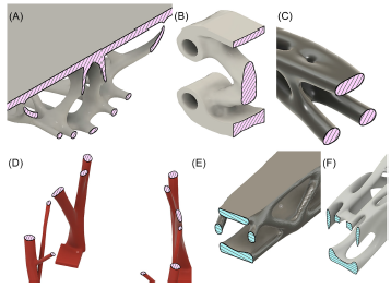
Despite the well understood structural performance gains associated with hollow geometries, none of the GD tools integrated into leading CAD packages such as Altair Inspire, CATIA, nTopology, Autodesk Fusion, Siemens NX, or Solidworks are capable of their generation. Figure 1 provides examples of structures generated by these six leading GD tools, demonstrating that all of them produce solid outcomes (none exhibit fully enclosed voids). The structures were all collected from the 3D model repository Grab-CAD (Stratasys Software, 2024). This alone is not evidence for lack of capability however the majority of these tools are likely based upon Reference Wang, Wang and GuoWang et al. (2003) Level Set Method (LSM) for structural TO due to its ability to provide smooth outputs processable using existing CAD functionality (Reference Yago, Cante, Lloberas-Valls and OliverYago et al., 2022). It has been shown that standard LSM does not allow for hollow 3D geometry (Reference Jia, Beom, Wang, Lin and LiuJia et al., 2011).
Examples of solid structures generated by a number of leading CAD packages. A) A shelf, Altair Inspire (Bracket man, 2021), B) A bracket, CATIA (Maxime Chagnot, 2019), C) A bottle opener, nTopology (Brandon Johnson, Reference Brandon2021), D) A chair, Autodesk Fusion (BURAK EVYAPAN, 2021), E) A drone chassis, Siemens NX (Il garage del Bicchio, 2023), F) A brake pedal, Solidworks (M95, 2022)

The inability of GD tools to produce hollow geometry constrains their performance, limiting the design space. This study proposes to test the hypothesis that lightweighting performance of GD tools can be augmented with the capability to generate hollow geometry. Some exploration of this has been conducted in literature to date.
Reference Fiore, Marano, Greco and MastromarinoFiore et al. (2016); Reference Wang, Jing, Liu, Song, Qie and XingWang et al. (2018) optimised parametrised members in predetermined truss and lattice structures respectively. In contrast, Reference Zhao, Hoang, Jang and ZuoZhao et al. (2021) procedurally generated a truss using predetermined hollow members while Bai and Zuo (2020) used Moveable Morphable Bars (MMB) to arrange parametrised box section members. Barberi et al. (2022) took another approach, optimising the size of holes in a structural plate. Despite their originality and all fve studies achieving mass reductions whilst maintaining structural integrity, none of these approaches serve for general TO problems since their starting and solution layouts and shapes are heavily constrained. Reference Watson, Leary, Downing and BrandtWatson et al. (2023) proposed a more versatile approach that uses image processing to replace regions of Solid Isotropic Material with Penalisation (SIMP) outcomes with tubes. While more applicable for general TO problems, this method still constrains solutions to specifc forms. Reference Jia, Beom, Wang, Lin and LiuJia et al. (2011) extended LSM by utilising Evolutionary Structural Optimisation (ESO) to create holes in low strain energy regions which can then be evolved by the traditional algorithm. This approach allows both the starting and solution shapes to take any form but is so far restricted to 2D geometries and so it is unclear whether it would produce hollow geometries in 3D. Furthermore, the majority of studies that evaluate GD and TO approaches only evaluate the theoretical performance of the resulting structures through the use of Finite Element Analysis (FEA). However, as studies such as that by Reference Peckham, Elverum, Hicks, Goudswaard, Snider, Steinert and EikevagPeckham et al. (2024) show, the AM process required to realise such complex geometries introduces signifcant variability and uncertainty making the real-world usability of experimental GD outcomes unclear.
In summary, whilst hollow structure generation has been explored in literature, no general approaches have been developed that can generate performant structural components in 3D. To address this, the contribution of this paper is twofold and lies in i) the proposal of a method to create hollow generative components via means of an off-the-shelf generative design package and an novel constant mass post-process shelling approach; and, ii) a feasibility evaluation of hollow structures created by this method via both FEA simulation and destructive testing of AM components.
The remainder of the paper is structured as follows. Section 2 begins with an explanation of the com-plete experimental method including the hypothesis, case study and approaches taken. Section 2.2 and Section 2.3 then explore the FEA and manufacture and subsequent destructive testing of the test structures. Next, Section 3 presents the results, showing the initial GD outcome, how it was modifed using shelling, and the two experiments. Section 4 then discusses the implications and opportunities associated with the method before the investigation is concluded with Section 5.
2. Methodology
The process for determining both the theoretical and real-world performance of the proposed structures is explained in the following section. Figure 2 demonstrates the steps taken, from initial structure generation, through shelling, theoretical evaluation using FEA, and fnally manufacture and destructive testing to assess the real world applicability of the technique.

A case study of a GD cantilever television bracket is used to test the feasibility of the proposed shelling techniques. The bracket has a 200mm span and four 5mm mounting holes positioned in a square with 100mm sides at either end. The case study was chosen due to its multiple fxing points and large span. The hypothesis in this paper is that shelled generative components will be stiffer than solid ones. To test this the following artefact types are compared:
-
Solid: A solid GD outcome
-
Standard shell: A 1mm outside shell applied to the solid outcome
-
Optimised shell: A shell with thickness optimised to maintain the mass of the solid outcome
The ‘Solid’ type is used as the control piece. The ‘Standard shell’ artefact type provides a method of evaluating whether off-the-shelf CAD shelling functionality can be used to improve the stiffness-weight of GD outcomes. Finally, the ‘Optimised shell’ type serves to explore the limits of lightweighting possible using shelling without deviating from the original target mass. This design of this fnal artefact employs the proposed constant-mass shelling method.
The relative theoretical stiffness of each artefact type is evaluated using the defection observed in the FEA studies. The regions of highest Von Mises stress in the results are also used to predict failure locations in the physical tests. Following physical testing, each structures stiffness is simply determined by the maximum load withstood and the defection that caused that load. The mean results from each of the artefact types are used to determine their real-world structural stiffness. One-way ANOVA and Tukey’s HSD statistical tests are used to determine whether any differences observed are signifcant.
2.1. Hollow generative artefact design
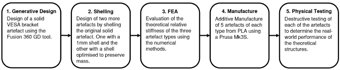
The ‘Solid’ artefact was designed using Fusion’s GD tool. Figure 3 shows the setup used to generate the structure. To mimic a cantilever use case, encastre constraints are applied to the fxed-end mounts and a remote force of 100N to the centre of the free-end mounts’ rear face. A remote load was used because it more accurately describes the intended use of the structure where all the free end mounts are co-constrained. Preserve regions were used at the mounting points with obstacle regions to leave clearance for fasteners. The tool was given a 90g material constraint using 1.24g/cm3 density PLA and the objective to maximise stiffness. An AM constraint in the +Z direction was also applied.
A) Isometric view of GD setup, B) Annotated and dimensioned side-on view of GD setup including the 140mm shelling span. The blue arrows depict the applied load

Two further structures were created by shelling the central 140mm of the bracket to produce the three artefacts. The shells were only applied to this central span to avoid interference with the mounts and fasteners. The second artefact uses an arbitrary 1mm thick shell.
The third, ‘Optimised shell’ artefact was designed using the proposed custom constant mass shelling methodology. The method iteratively applies outside shelling to the geometry using a Nelder-Mead opti-miser until it converges on a shell thickness that gives a structure of the same mass as the original solid case (Nelder and Mead, Reference Nelder and Mead1965). Outside shelling is used as it distributes material outwards, increasing the second moment of area. An implementation of this approach as an Autodesk Fusion add-in can be found in the ‘Open Access’ section.
2.2. FEA
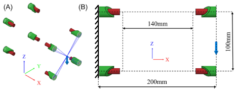
The complexity of the artefacts’ geometry makes it prohibitively diffcult to analytically model the structures so FEA was used to investigate the impact the shelling operation has on the stiffness of the structure. For this, Ansys Mechanical was used to solve a static structural test for each of the designs using identical setups that mimicked the original structure generation conditions shown in fg. 3 (Ansys Inc., 2024). The maximum defection and highest regions of Von Mises stress were recorded during each analysis allowing for design stiffness to be calculated and points of failure to be predicted. An example test setup is shown in fg. 4(A), with a remote load of 100N applied in the -Z direction at the centre of the free end of the structure, and encastre supports applied at the fxed end. This is deliberately designed to replicate the generation conditions in fg. 3. Since the FEA experiment aims to determine any relative differences in structural stiffness between artefacts, a standard elastic isotropic material was used. As such, PLA properties were applied to all artefacts. The material has a Young’s modulus of 3.15GPa and Poisson’s ratio of 0.33 (Kuentz et al., Reference Kuentz, Salem, Singh, Halbig and Salem2016).
Tet10 elements were used to mesh all the components due to their suitability at capturing complex geometry (Zienkiewicz et al., Reference Zienkiewicz, Taylor and Fox2014). Figure 4(B) shows an example meshed structure. The multiscale analysis required by this investigation is challenging and so solid elements were used globally to avoid inconsistencies and inaccuracies in transition between element types. Mesh convergence studies were performed for each artefact type to ensure that the results presented are mesh independent. In each case, the mesh converged with 2% maximum Von Mises stress deviation when the mesh size was less than a third of the structure’s minium thickness; a rule of thumb recommended by Kim et al. (Reference Kim, Sankar and Kumar2018) when uing solid elements to analyse thin walled structures.
A) The problem setup, the faces circled in green have encastre constraints whilst the red faces and arrow depicts the remote load, B) An example meshed structure

2.3. Manufacture and physical testing
The artefacts were all manufactured on a single Prusa Mk3S with a 0.4mm nozzle using Raise3D High Speed White PLA Filament and identical slicer confgurations (Prusa3., 2024; RS Components, 2024). Where possible Prusaslicer’s default machine, PLA and print settings (as of November 2024) were used. The notable or non-default print settings are listed below:
-
100% infll • 215°C nozzle temperature
-
Rectilinear infll pattern • 60°C bed temperature
-
0.4mm wall thickness • All artefacts were manufactured in the
-
Organic support material same orientation with their +Z axis
-
Support on build plate only upwards
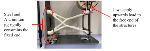
The physical tests were performed with a SHIMADZU AGS-X and a 10kN load cell. A 5mm plate steel and aluminium extrusion jig was used with four M5 fasteners at each end to rigidly constrain the artefacts. The SHIMADZU jaws were then used from above to test in a cantilever confguration. The displacement of the jaw was ramped at a constant 10mm/min until failure for all tests. Figure 5 depicts the test setup. Five samples of each artefact type were tested. This number was chosen due to scheduling restrictions and the quantity used in similar studies such as that by Chacón et al. (2017).
Image of the test setup with an artifact fxed into the SHIMADZU tensile tester

3. Results
The results from each of the steps described in Section 2 are presented below.
3.1. Hollow Generative Artefact Outcomes
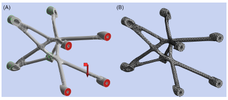
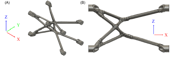
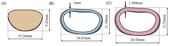
Figure 6 shows the output of Fusion’s GD tool. The application of a 1mm and a constant mass shell resulted in two further structures with crosssections as shown in fg. 7. The constant mass shelling tool found the optimal shell thickness to be 1.509mm using with a 0.5g tolerance stopping condition. This gave the following design masses: ‘Solid’) 92.0g; ‘Standard shell’) 72.9g; ‘Optimised shell’) 92.4g. The computational cost of the constant mass thickness optimisation was high, taking 55m 43s to complete 15 iterations with a 12th Gen Intel(R) Core(TM) i7-1270P 2.20GHz processor and 32GB of RAM.
A) Isometric view of the GD outcome, B) Side view of the GD outcome

Section views of the three artefact types: A) ‘Solid’, B) ‘Standard shell’, C) ‘Optimised

3.2. FEA
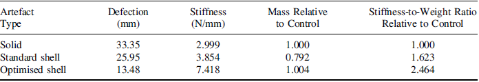
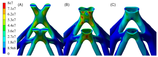
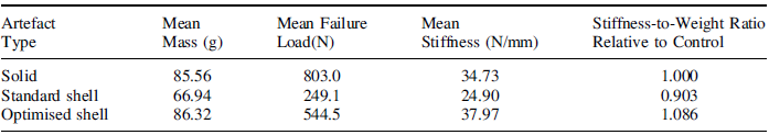
Table 1 lists the results from each of the FEA studies. The calculated stiffness for each artefact type supports the hypothesis that post-generation shelling can be used to increase structural stiffness. Furthermore, the stiffness-to-weight ratio relative to the control values suggests that increasing shell thickness results in superlinear growth in structural stiffness. This effect is pronounced enough that the ‘Standard shell’ artefact was found to be 28.5% stiffer than the ‘Solid’ artefact despite being 20.8% lighter. The stress distribution in each of the artefacts is shown in fg. 8. The high stress locations are of particular interest since they indicate potential failure points. The fexural load on each of the components is clear due to the increasing stress away from the neutral axis. Also apparent is the ‘Optimal shell’ artefact’s ability to distribute the load effciently, with its maximum Von-Mises stress 33.5% and 45.1% lower than the ‘Solid’ and ‘Standard shell’ artefacts respectively.
The results from the FEA study of each design.

Von-Mises stress (Pa) distribution in each of the artefacts

3.3. Physical tests
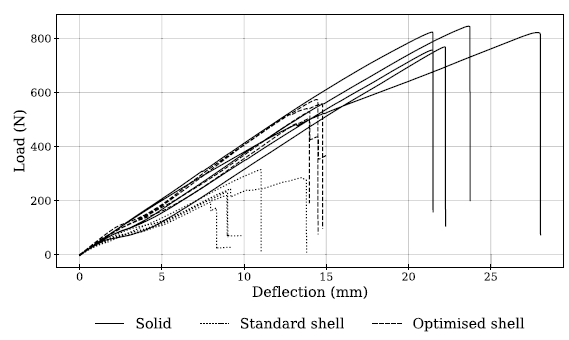
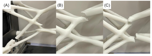
The load required to deflect each artefact is shown in fig. 9. Table 2 records the relevant values. The large stiffness increases in the shelled artefacts observed in the FEA was not demonstrated in the physical tests. The ‘Standard shell’ artefacts were the least performant with a 29.4% lower mean stiffness than that exhibited by the ‘Solid’ artefacts and a 10.0% lower stiffness-to-weight ratio. This difference is statistically significant with an adjusted p-value of 2x 10⁻⁴ indicating that the result reflects consistent real world weakness. Meanwhile, the ‘Optimised shell’ artefacts’ calculated mean stiffness is 9.5% higher than that of the control ‘Solid’ artefacts. However this difference is not significant with an adjusted p-value of 0.1533 suggesting that the ‘Optimised shell’ artefacts are not meaningfully stiffer. The clearest difference between the artefact types can be observed in their failure loads. The ‘Solid’ artefacts failed at 222.3% and 47.5% higher loads on average than the ‘Standard shell’ and ‘Optimised shell’ artefacts respectively. Both these differences are statistically significant with p-values less than 1 x 10⁻⁴. This demonstrates that the ‘Solid’ AM artefacts can withstand higher loads before yielding. All the artefacts of each type failed similarly Examples of these failures are presented in fig. 10. The high stress regions in fig. 8 predict the repeated failure of the shelled artefacts. The shelled artefacts fractured across multiple layers, suggesting that the stress has exceeded the Ultimate Tensile Strength (UTS) of the material. The ‘Solid’ artefacts broke more cleanly in an unexpected location and with horizontal fractures, suggesting that those structures instead broke due to layer separation. Polymer Material Extrusion (MEX) AM as performed in this study produces structures with highly unpredictable material properties. Infill pattern, build direction and cooling rates all have high impacts on UTS.
Loading applied to each artefact as the tensile tester ramped deflection

The mean performance characteristics for each of the artefact types.

Example failures for artefact types: A) Solid, B) Standard shell, C) Optimised shell

4. Discussion
The results of the FEA studies indicate that shelling can be used to increase the theoretical stiffness of GD outcome structures. The shelling method used provides a more general form of hollowing capable of creating general crosssections than that offered by other TO approaches which are mostly limited to parametrised tubes. Furthermore, the optimised shell thickness artefact designed by the Fusion add-in demonstrates that the benefts are achievable without violating the designer’s mass target. As such, the constant-mass shelling tool could form the fnal stage of an automated GD toolchain that aims to maximise stiffness. As mentioned in Section 3, the computational cost of the constant mass shelling tool’s use is high for the complex case study used in this study, but if integrated into the cloud computing processes employed by existing GD toolchains such as Fusion’s, the real time could be shortened. The act of outside shelling structures as above increases the bounding box of some regions of the component (and therefore potentially the component overall). This may be undesirable since it could cause interferences. Any designers that use shelling in this way should be aware of this fact and could take steps to mitigate it by introducing measures such as using Fusion’s ‘obstacle offset’ feature to pre-emptively give the structure room to expand. Similarly, to avoid undesirable intersections this paper shelled only the 140mm central span of the 200mm long cantilever structure. Future implementations of the method could instead shell all the non-preserve regions of the GD setup.
The FEA in this investigation used basic techniques to minimise possible inaccuracies. A constant sized mesh across the entire model and solid elements even in the thin walled regions prevented the need for different mesh types. This simplifed approach has limitations such as the presentation of hourglass modes and shear locking when using solid elements to model thin structures (Trung, 2023; Kim et al., Reference Kim, Jang and Choi2023). Despite these potential errors, the high stress regions in fg. 8 predict the repeated failure of the shelled artefacts as seen in fg. 10, suggesting the simulation has adequate prediction capability. The layer separation failure mode of the ‘Solid’ artefacts suggests that they principally broke due to the anisotropy of AM components. The predictable and earlier failure of the shelled components meanwhile implies a lower material UTS in all directions. This is likely due to the faster heat dissipation from thin walled structures which reduces material strength (Goudswaard et al., Reference Goudswaard, Hicks and Nassehi2018). A further factor that may have decreased the load bearing capability of the shelled artefacts are the low bead overlaps present in thin walled components due to the rapid cooling. These lead to voids that may reduce material UTS although this effect is likely not highly represented in this study since the printed shelled artefacts were all within 2% of their predicted mass.
The method of evaluating the physical artefacts stiffness using only the max load and defection at that max load provides a simplistic view of stiffness. It is clear in fg. 9 that further effects are present and stiffness is non-constant as the structures defect for example due to shear slippage. Despite this it is clear that the theoretical value of shelling suggested by the FEA is not achievable using PLA AM due to anisotropy the low strength of regions that are only a few layers thick.
This study only considers a fexural load state. The complexity of the case study was designed such that a fexural load promotes more complex stress states in its sixteen struts. As such, this study aims to provide analysis regarding the general feasibility of structural shelling as a form of lightweighting. However, further investigation is required to validate the performance of hollowed structures under specifc multi-axial load cases. If torsional load is applied to constant mass shelled structures the performance will be increased relative to their solid counterparts due to increased crosssectional second moment of area. Under axial tension or shear load conditions constant mass shelled components are likely to perform similarly to solid components due to a necessarily constant crosssectional area. In axial compressive cases however the thin walls of shelled structures may make them particularly prone to buckling. Although this paper demonstrates potential benefts of hollow GD outcomes, further steps could be taken to leverage the advantages. This investigation used shells of uniform thickness in all instances which serves as a further constraint. Optimising the wall thickness in different regions may enable further lightweighting advantages. Further, shelling could be selectively in specifc regions to prevent buckling under compression. Also the GD approach that generated the original solid structure in this study did not consider the geometry as shelled during its optimisation. Use of a more general hollow GD method which is capable of evaluating voids during each iteration could improve structural performance. To realise the benefts of hollow outcomes in the real world an AM process that produces more isotropic material properties such as SLA is recommended (Zohdi and Yang, Reference Zohdi and Yang2021).
The proposed shelling methodology has the potential to improve the performance of existing structural GD tools. This process could be benefcial across a range of domains where mass reduction is a primary objective such as in civil structural engineering or the aerospace industry. Due to the complexity of output geometries the approach is likely only suitable in situations where AM can be employed. The method could be particularly suitable for part consolidation in applications that already leverage hollow or tubular geometries such as bicycle, low cost automotive or furniture manufacture.
5. Conclusion
The fndings of this investigation demonstrate the potential of shelling techniques to improve the per-formance of GD structures, particularly in terms of stiffness-to-weight ratios. The proposed shelling approach, particularly the constant-mass optimization tool, showcased its ability to enhance stiffness without exceeding initial mass constraints, providing a feasible pathway to improved lightweighting outcomes without disruption to the designer’s objectives.
Despite these advances, the study revealed notable discrepancies between theoretical predictions and experimental results. These are attributed primarily to the anisotropy and variability of AM produced thin-walled components. Further refnement of manufacturing techniques to enhance material isotropy and strength, such as using SLA could bridge the gap between simulated and experimental performance. Future work should explore the development of GD approaches inherently capable of producing hollow geometries, thereby eliminating the need for post-generation modifcations.
Acknowledgments
EPSRC DTP 2020-2021 University of Bristol Grant Ref EP/T517872/1.
Open Access
The constant mass lightweighting tool: https://doi.org/10.5281/zenodo.14999128

 Open access