Introduction
In this article, I reflect on 20 years of my research in the field of carbon nanomaterials and provide my vision of this exciting and quickly growing field. Graphene is the latest example and is now the most widely researched carbon structure, but other carbons deserve attention as well. I first describe carbon nanomaterials in general, to present an overview of the world of carbon nanostructures and to highlight their most promising applications. Then, I use the example of supercapacitor electrodes to show how to select different materials, design the required structures from carbon, and match them to specific electrolytes to achieve target properties. Structural and energy-related applications of carbon nanotubes and graphene are described in more detail in the sidebars. At the end, I briefly introduce a new family of carbon-based materials, namely, two-dimensional (2D) transition-metal carbides (MXenes), which have a planar 2D structure similar to that of graphene, MoS2, or clay and show great potential for energy storage and a variety of other applications.
The large family of nanostructured carbons
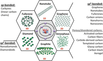
About three years ago, I wrote a commentary titled “Not Just Graphene.” Reference Gogotsi1 This title was chosen because we scientists behave like children when we have new toys. Whenever there is a new material, we get excited, and we start playing with it. First were fullerenes Reference Kroto, Heath, O’Brien, Curl and Smalley2 and carbon nanotubes; Reference Iijima3 today, everyone works on graphene. Reference Novoselov, Jiang, Schedin, Booth, Khotkevich, Morozov and Geim4 However, what is exciting about the world of carbon is that it is so rich; there are so many different materials available ( Figure 1 ). Whereas graphene is currently “hot,” this article discusses a great variety of carbons. The special electronic structure of the carbon atom allows it to adopt sp, sp 2, and sp Reference Iijima3 hybridizations, resulting in the ability to form a diversity of nanostructures. Reference Gogotsi5 Carbon is unique in this sense. We could build a world made entirely of carbon-based structures if we knew how to design with carbon, and a few examples are shown here. But it is exactly this variety, this richness of the carbon nanoworld, that also makes it very difficult for engineers to select the right material for a specific application.
The most common carbon materials classified based on their bonding (hybridization of orbitals of carbon atoms) and dimensionality (i.e., the number of dimensions not confined to the nanoscale). Whereas graphite, carbon fibers, glassy carbon, activated carbons, carbon black, and diamond are already widely used in industry, fullerenes and fullerides, carbon onions (multishell fullerenes), nanotubes, whiskers, nanofibers, cones, nanohorns, nanorings, nanodiamonds, and other nanoscale carbons are being explored for future technologies. Note: 0D, zero-dimensional; 1D, one-dimensional; 2D, two-dimensional; 3D, three-dimensional. Courtesy of V. Presser.

So, how does one answer the question: “Which carbon material is the best for use in a specific component or a device?” Although sp-bonded carbon materials, carbynes, exist, we still do not know how to produce them in large quantities, not just a few atoms in a chain. Linear carbon chains have been seen inside carbon nanotubes but not in bulk quantities. Reference Zhao, Ando, Liu, Jinno and Suzuki6 Such carbons do not yet have any engineering applications.
This article primarily focuses on sp 2-bonded carbons because of the included case study on supercapacitors, an application that requires high conductivity. Reference Simon and Gogotsi7 The π-electrons in sp 2-bonded carbon materials such as graphene and nanotubes make these materials electrically conductive, and this is a very important property for many applications of carbons. But even if we consider just sp 2 carbon, the variety of carbon forms is astounding: graphene, nanotubes, fullerenes, onion-like carbon (multishell fullerenes), nanohorns, nanocones, rings—and this list goes on. Reference Gogotsi and Presser8
The most common sp 2-bonded carbon materials used commercially are graphite, activated carbon (activated charcoal), carbon black, and carbon fibers. These materials are abundant and readily available; their use in the electrodes of batteries and supercapacitors make our computers and cell phones work. But what do we really need for a specific application?
Graphene can be considered to be a basic element, from which a graphite crystal can be built. By introducing pentagonal defects, one can produce fullerenes (closed carbon shells), or a graphene sheet can be rolled into a seamless cylinder to make a carbon nanotube. Yet, within every family, there is again an enormous richness of structures. A large variety of fullerene shells can be formed starting from C20 and going to a much larger number of carbon atoms in each shell, with C60 being the most stable. Reference Rao, Seshadri, Govindaraj and Sen9
Figure 2 shows various carbon nanotube forms. There are single-wall tubes (Figure 2b) with 1-nm or even smaller diameters, but even these can be metallic or semiconducting; armchair, zigzag, or chiral (Figure 2a). Reference Ajayan and Ebbesen11 There are double-wall, triple-wall, and multiwall nanotubes (Figure 2c–g), with a scroll or seamless cylinder structure. They can contain catalyst particles (Figure 2e and j) or be metal-free; they can be cylindrical, polygonal (Figure 2g), or even conical (Figure 2h). Reference Gogotsi10,Reference Gogotsi, Libera, Kalashnikov and Yoshimura12 When they grow to larger diameters, there is a smooth transition to carbon nanofibers (Figure 2i–k), with diameters of hundreds of nanometers to micrometers or even larger, but there is no distinct border between carbon nanofibers built of coaxial or scrolled shells and carbon nanotubes.
A few representative examples of a large family of 1D carbon structures with diameters ranging from 1 nm to hundreds of nanometers. (a) Schematic showing armchair, zigzag, and chiral single-wall nanotubes (from left to right), (b) single-wall carbon nanotube, (c–d) multiwall carbon nanotube (MWCNT) with no catalyst, (e) MWCNT with a catalyst particle, (f) large cylindrical MWCNT, (g) 1D graphite crystal with a nonagonal cross section, (h) carbon cone, (i) graphite polyhedral crystal with multiple tips (arrow shows a tip formed by five faces, probably due to a pentagonal defect), (j) large hydrothermally grown microtube with a nickel catalyst particle in the tip, and (k) thin MWCNT in the core of a larger nanofilament. (b–e and h) are transmission electron microscope images; others are scanning electron microscope images. Reproduced with permission from Reference Reference Gogotsi10. © 2003 Maney Publishing.

Clearly, carbon nanotubes alone represent a large family of materials. Multiwall nanotubes are already used in composites or as conductive additives to battery electrodes. Carbon rings can be produced by bending nanotubes. Reference Wang, Laird, Gogotsi and Li13 There are also many conical carbon structures ( Figure 3 ). Sumio Iijima, who is credited with spurring scientific interest in nanotubes, also reported nanohorns (Figure 3a and d). Reference Iijima, Yudasaka, Yamada, Bandow, Suenaga, Kokai and Takahashi14 Nanocones (Figure 3b) and microscopic cones with different apex angles can be produced by introducing pentagons in the tip (Figure 3e) or disclinations (Figure 3f) in carbon sheets. Reference Jaszczak, Robinson, Dimovski and Gogotsi15
Carbon nanohorns, cones, and onions. (a) Transmission electron microscope (TEM) image of nanohorns, (b) scanning electron microscope image of a natural conical graphite crystal, (c) TEM image of carbon onions, (d) model of a cluster of nanohorns, (e) model explaining the formation of conical structures by incorporation of one or more pentagons in a graphene sheet, (f) model describing conical growth as a result of disclination in a graphene sheet, and (g) model of a carbon onion. (a and d) Reproduced with permission from Reference Reference Iijima, Yudasaka, Yamada, Bandow, Suenaga, Kokai and Takahashi14. © 1999 Elsevier. (b, e, and f) Reproduced with permission from Reference Reference Jaszczak, Robinson, Dimovski and Gogotsi15. © 2003 Elsevier. (c) Courtesy of G. Yushin (Georgia Institute of Technology, Atlanta, Ga.).

sp Reference Iijima3 carbon (diamond) also comes in very small dimensions, such as ∼5-nm particles that can be produced in large quantities at a moderate price by simply placing an oxygen-lean explosive in a closed chamber and detonating it. Reference Mochalin, Shenderova, Ho and Gogotsi16 Nanodiamonds mixed with graphitic soot can then be scraped off the walls of the chamber. Nanodiamonds have already found applications in lubricants and nanocomposites, and their use in biomedical imaging and drug delivery is also being explored. Reference Mochalin, Shenderova, Ho and Gogotsi16 Annealing at high temperatures can transform diamond nanoparticles into multishell fullerenes, called “carbon onions” (Figure 3c and g), Reference McDonough, Frolov, Presser, Niu, Miller, Ubieto, Fedorov and Gogotsi17 which have been explored for applications in electrical energy storage and conducting carbon inks.
Although a variety of additional carbon nanostructures could be described, it is important to mention that widely used inexpensive conventional carbon materials, such as the activated carbon used for filtering water, also have nanoscale features: pores with diameters of a couple nanometers and less-than-nanometer-thick pore walls. These materials also come in a variety of structures. However, when a natural precursor is used to make carbon, it is very difficult to control the structure and properties such as porosity. When a synthetic inorganic precursor, such as a carbide, is used, the number of carbon atoms per unit of volume of this crystalline structure is known exactly, and extracting the metal at elevated temperatures produces a carbon with well-controlled pore size by the following reactions: Reference Presser, Heon and Gogotsi18
SiC + 4H2O = C + Si(OH)4 + 2H2 (1)
TiC + 2Cl2 = C + TiCl4. (2)
Recently, a new method for producing such carbide-derived carbons (CDCs) was reported that involves electrochemical etching of carbides at room temperature, rather than the high temperatures required for hydrothermal or halogenation syntheses. Reference Lukatskaya, Halim, Dyatkin, Naguib, Buranova, Barsoum and Gogotsi19
It is possible to control the structure, pore size, and density of CDCs by taking a specific carbide structure with desired properties and further tuning these properties by changing the synthesis parameters, such as temperature. For example, SiC having a diamond cubic lattice and a ternary metal carbide with a layered structure (MAX phase, with the general formula M n+1AX n , where M is an early transition metal, X is carbon or nitrogen, and A is an A-group element such as Si or Al) have different pore-size distributions. Reference Presser, Heon and Gogotsi18 At the same chlorination temperature, a very narrow distribution with an average pore size close to 8 Å is observed in the former case, whereas a multimodal distribution with larger, nanometer-scale slit pores occurs in the latter case (Ti2AlC or Ti3SiC2). Reference Presser, Heon and Gogotsi18
The carbon obtained by extracting metal atoms from carbides will not necessarily stay in an ordered structure. Usually, amorphous networks are produced. CDCs can stay disordered even at a synthesis temperature of 1200°C ( Figure 4 ), unless one uses carbides of metals having catalytic properties, such as Fe3C, Reference Dimovski, Nikitin, Ye and Gogotsi21 which leads to the formation of graphene sheets. No fringes could be found in transmission electron microscopy (TEM) images of samples synthesized at lower temperatures (down to 200°C), Reference Perez, Yeon, Segalini, Presser, Taberna, Simon and Gogotsi22 and there was more ordering in the three-dimensional (3D) network at higher temperatures (Figure 4c), as the long-range order increased.
Quenched molecular dynamics snapshots (4 × 4 × 2 nm3) representing TiC carbide-derived carbon structures produced at different temperatures. (a) Fast quenching, 600°C; (b) medium quenching, 800°C; and (c) slow quenching, 1200°C. Surface termination was not taken into account. Reproduced with permission from Reference Reference Palmer, Llobet, Yeon, Fischer, Shi, Gogotsi and Gubbins20. © 2010 Elsevier.

Highly ordered carbon structures, including graphite, graphene, and nanotubes, Reference Cambaz, Yushin, Osswald, Mochalin and Gogotsi23 can be produced by vacuum extraction of Si from SiC at temperatures above 1200°C by the reactions:
SiC = Si + C (3)
or
2SiC + O2 = 2SiO + 2C. (4)
Thus, selective extraction alone Reference Naguib and Gogotsi24 can generate a large variety of carbons, ranging from amorphous porous CDCs to graphene and nanotubes, Reference Presser, Heon and Gogotsi18 but numerous methods for making carbon materials are available today that can produce almost any structure needed.
Carbon electrodes for capacitive energy storage
This section explores the need for many different carbons with different structures and properties using the example of electrochemical energy storage, specifically supercapacitor electrodes. Supercapacitors, which are also known as electrical double-layer capacitors, ultracapacitors, or electrochemical capacitors, are somewhat like batteries: they come in similar shapes and sizes and are also used to store electrical energy. Reference Conway25 Unlike in batteries, however, energy storage in supercapacitors occurs by fast adsorption (electrosorption) of ions on high-surface-area conducting electrodes. When the electrode is charged, oppositely charged ions are attracted to the surface.
These devices are called supercapacitors because, unlike electrolytic or solid-state capacitors, which are usually rated for micro- or millifarads, they can have capacitances of hundreds or even thousands of farads because of the large surface areas of the electrodes (typically exceeding 1000 m2/g). When a battery in a computer or cell phone is discharged, it maintains the same voltage, and the voltage drops quickly at the end of discharge. When a supercapacitor is discharged or charged at a constant current density, there is a linear change in potential with time. The cyclic voltammograms also look different, being rectangular for the supercapacitor ( Figure 5b) but having clearly pronounced and separated peaks in the case of batteries.
Carbon-based electrodes for supercapacitors. (a) Schematic showing the use of a multiwall carbon nanotube (MWCNT) forest with a mixed room-temperature ionic liquid (RTIL) electrolyte for capacitive energy storage in a very broad temperature range. (b–c) Cyclic voltammograms of MWCNT arrays grown on aluminum foils and tested in a 1:1 eutectic mixture of N-methyl-N-propylpiperidinium bis(fluorosulfonyl)imide (PIP13FSI) and N-butyl-N-methylpyrrolidinium bis(fluorosulfonyl)imide (PYR14FSI) RTILs as the electrolyte (b) at –20°C, 20°C, and 100°C at 100 mV/s and (c) at –40°C and –50°C at 5 mV/s. Note the wider voltage window at low temperatures. Adapted with permission from Reference Reference Lin, Taberna, Fantini, Presser, Perez, Malbosc, Rupesinghe, Teo, Gogotsi and Simon26. © 2011 American Chemical Society.

Supercapacitors bridge the gap between electrolytic capacitors and batteries. They have higher power densities than batteries and can be charged or discharged within seconds. On the other hand, they have lower total energy densities than batteries. So they can provide high power, but it is also important to remember that, within a short time, they are able to store or harvest more energy than any battery. Supercapacitors can also be made of carbon-based materials and safely discarded (incinerated). Reference Dyatkin, Presser, Heon, Lukatskaya, Beidaghi and Gogotsi27 Safe disposal is becoming increasingly important as more and more electrical energy-storage devices are going into the trash after the end of their lifetime or the lifetime of the systems they power.
The principles of operation and use of supercapacitors were recently described in two articles in MRS Bulletin. Reference Ball28,Reference Ball29 For example, the use of supercapacitors in regenerative breaking on trains and trams saves about 30% of the energy. In the case of gantry cranes, the energy consumption from diesel generators can be decreased by 40% by implementing supercapacitors for energy recovery. Supercapacitor-powered buses can be seen on Shanghai streets. Instead of having a very large battery that would last for 8 h but would then have to be removed for recharging, these buses have a supercapacitor module on the roof. Although the supercapacitor can power the bus for only a few-kilometer ride, it can be fully charged at every bus stop during the short time when people get on and off the bus.
It is important to think outside the box when developing new storage solutions utilizing supercapacitors. Another example is the fully autonomous bus stops installed in remote areas of Japan. The roof is made of solar panels, two light-emitting diodes provide illumination, and there is a supercapacitor module under the bench. Why not a lead-acid or a lithium-ion battery? The answer is simple: Supercapacitors have lifetimes of up to a million cycles due to electrostatic energy storage, enabling the entire system to be maintenance-free for 10 years. Supercapacitors can also be made small and wearable; be embedded into textiles and flexible devices to power radio-frequency identification tags, sensors, and electronics; and be used in many other applications.
Carbon is uniquely suited for supercapacitor electrodes because it can form highly conductive porous solids with high surface areas for ion adsorption and atomically thin pore walls. Reference Simon and Gogotsi7 The performance of a supercapacitor electrode depends on its conductivity and surface area. Moreover, depending on the carbon morphology, different dependencies of capacitance on structural feature size are observed ( Figure 6 ). For spherical (onions) or tubular (nanotubes) particles, there is an increase in capacity with decreasing size. Reference Huang, Sumpter, Meunier, Yushin, Portet and Gogotsi30 Micro- and mesoporous carbons exhibit opposite dependencies of capacitance on pore size.
(a) Effects of particle and pore size on the capacitance of carbons normalized by the surface area. The inset shows microporous carbon with a pore size smaller than solvated-ion size. (b–c) Schematics of solvated ions adsorbed (b) on the outer surface of a carbon onion or nanotube (CNT) and (c) inside a mesopore (pore larger than 2 nm in diameter). When the particle or pore size is large, all curves asymptotically approach the horizontal line representing a parallel-plate capacitor, which might be the case for pillared graphene or MXene. Reproduced with permission from Reference Reference Huang, Sumpter, Meunier, Yushin, Portet and Gogotsi30. © 2010 Cambridge University Press.

In addition to a carbon electrode, it is necessary to select an electrolyte. Whereas numerous carbon materials are available for the electrode, there are thousands of electrolytes that may be matched to the carbons. Reference Simon and Gogotsi7 They include safe and inexpensive aqueous solutions of acids, bases, and salts, as well as organic electrolytes. Organic electrolytes, such as tetraethylammonium tetrafluoroborate in acetonitrile or propylene carbonate, are used to increase the voltage window because of the relationship between energy stored, E; capacitance, C; and voltage, V: Reference Conway25
E = 1/2 CV 2. (5)
Water splitting limits the voltage window for symmetric aqueous-electrolyte devices to less than 1.2 V, whereas organic electrolytes can operate at 2.5–2.7 V. Organic salts that are liquid at room temperature (i.e., room-temperature ionic liquids [RTILs]) can be stable above 3 V, further increasing the energy density at the same capacitance. So the question arises: How does one match a specific carbon to a specific electrolyte? This cannot be done by randomly selecting a “good” high-surface-area carbon and a “good” conducting electrolyte.
To match the carbon pore size to the electrolyte ion size, our group produced a number of CDCs with narrow pore-size distributions, ranging from less than 7 Å to about 11 Å, all of which had maximum pore sizes smaller than the solvated ion size of the organic electrolyte. Reference Chmiola, Yushin, Gogotsi, Portet, Simon and Taberna31 It is well-known that ions are solvated in solution, and conventional wisdom suggests that ions surrounded by a solvation shell need to line up within pores to provide electrostatic energy storage in a supercapacitor, thus requiring pores of several nanometers in size.
The results that we obtained were very surprising. Reference Chmiola, Yushin, Gogotsi, Portet, Simon and Taberna31 We expected capacitance to drop to nearly zero for pore sizes below around 1 nm (i.e., 10 Å), in contrast to the larger pores studied earlier, because this pore size was smaller than the solvated ion size. Instead, capacitance increased dramatically with decreasing pore size. A natural and very simple explanation is that the ions enter the pores without their solvation shells, having been completely or at least partially desolvated. Reference Chmiola, Largeot, Taberna, Simon and Gogotsi32 As a result, more ions can be packed onto the same surface area, and the distance between the charges becomes smaller, leading to a larger capacitance. This seemingly simple result led to a dramatic change in the capacitive energy-storage field, attracting the attention of electrochemists and materials scientists and moving computational scientists into this field. Modeling very quickly showed that ion desolvation is expected for small pore sizes. Reference Huang, Sumpter and Meunier33
A tremendous amount of atomistic modeling has been done over the past few years since that work to understand the absorption and confinement of ions at surfaces and in pores. Reference Feng, Qiao, Huang, Sumpter and Meunier34–Reference Kondrat, Perez, Presser, Gogotsi and Kornyshev37 The next step was to move from solvated electrolytes to ionic liquids, which are solvent-free and nonflammable and have very low vapor pressures. Potentially, they could be excellent electrolytes, but they are viscous and require high-temperature operation. They also provide a good model system to study what happens when ions do not have a solvation shell.
We found that the maximum capacitance for a CDC–ionic liquid system was obtained when the pore size matched the ion size. It is very important to mention that a 1-Å change in pore size was found to lead to about a 50% change in capacitance. Reference Lin, Huang, Segalini, Largeot, Taberna, Chmiola, Gogotsi and Simon38 When pores are too small, ions simply cannot go into the pores. When pores are too large, no more than one ion can fit into a 1-nm pore if the ion size is 6–7 Å. Thus, a very narrow pore-size distribution is required to achieve the maximum capacitance, and materials must be controlled with subangstrom accuracy to achieve the maximum performance.
Modeling using molecular dynamics (MD) and ab initio approaches quickly confirmed that there are oscillations of capacitance as a function of pore size, with the largest capacitance at the pore size corresponding to the ion size. Reference Feng and Cummings36,Reference Jiang, Jin and Wu39,Reference Wu, Huang, Meunier, Sumpter and Qiao40 Second and third peaks appear because two and three ions can fit into a pore. However, most computational studies have been done on idealized cylindrical pores as are found in carbon nanotubes or on slit pores as appear in graphene or graphite, whereas real activated or carbide-derived carbons do not have straight slit pores (Figure 4a–c). They do not have cylindrical pores either: They are 3D amorphous networks. Gubbins’s group produced models of carbide-derived (Figure 4a–c) and activated carbons, Reference Palmer, Llobet, Yeon, Fischer, Shi, Gogotsi and Gubbins20 and Salanne’s group performed MD simulations showing how ions enter the pores of disordered carbons. Reference Merlet, Rotenberg, Madden, Taberna, Simon, Gogotsi and Salanne41 In the case of ionic liquids, the simulations showed that negative ions drag positive ions along and vice versa ( Figure 7 ), so that there are always counterions penetrating into pores. Thus, the very empirical field of capacitive energy storage, where devices were made by trial and error by mixing activated and other carbons with electrolytes, transitioned into science-driven selection and design of carbon electrode–electrolyte combinations within just a few years.
Supercapacitor simulation using the 1200°C carbide-derived carbon model shown in Figure 4c. (a) The simulation cell consists of a 1-n-butyl-3-methylimidazolium hexafluorophosphate (BMI-PF6) room-temperature ionic liquid electrolyte surrounded by two porous carbons held at constant electrical potentials (blue, C atoms; red, three sites of BMI+ ions; and green, PF6 – ions). (b) Structure of the electrode for various voltages (ψ). For each value, the same snapshot is shown twice: (left) ionic distribution and (right) degree of charging of the electrode atoms, where the carbon atoms are colored according to the charge q that they carry (green, q < 0; red, q > 0; and yellow, q = 0). Reproduced with permission from Reference Reference Merlet, Rotenberg, Madden, Taberna, Simon, Gogotsi and Salanne41. © 2012 Nature Publishing Group.

At a certain point, we were satisfied with our findings and naively assumed that we knew how to make the best supercapacitor electrodes. We produced and tested CDC films ranging from microns to 200 μm in thickness with micropores tuned to the size of ions and with no meso- or macroporosity, Reference Chmiola, Largeot, Taberna, Simon and Gogotsi42 and we expected them to provide higher gravimetric and volumetric capacitances than conventional powder electrodes. Indeed, we obtained a value of 180 F cm–3, which is three times that of a commercial supercapacitor electrode, but for just 1-μm films. As the film’s thickness increased, the capacitance decreased, actually going below the level of activated carbon. The reason for this is simple: In a 100-μm-thick film with 1-nm pores, an ion must jump through 100,000 pores to reach the current collector. Apparently, diffusion limitations do not allow all of the pores to be filled to fully charge the electrode.
To make a device that can be charged very quickly, one must use carbon materials that do not have internal porosity, such as carbon nanotubes, onions, and nanohorns (Figures 2 and 3), where the accessible area is on the outer surface of the particles (Figure 6b). A device made using carbon onions can be charged at up to 100 V s–1. Reference Pech, Brunet, Durou, Huang, Mochalin, Gogotsi, Taberna and Simon43 A microsupercapacitor device operated at 2.7 V can be charged in milliseconds. By using a carbon-onion microsupercapacitor, a specific energy comparable to that of thin-film batteries can be achieved, but with a specific power in the range of those obtained with electrolytic capacitors. By increasing the power and charge/discharge rate, it is possible to use supercapacitors in electronic applications and AC–DC conversion, where electrolytic capacitors are currently used.
By correctly selecting the carbon material, it is possible to overcome other challenges. For example, activated and other microporous carbons work only at elevated temperatures, and no porous carbons can operate at temperatures below room temperature with RTIL electrolytes. However, when open structures, such as carbon onions, nanotubes, or graphene, are used, diffusion limitations can be eliminated. Specifically, we constructed a supercapacitor using multiwall carbon nanotube electrodes with a eutectic mixture of RTILs that remains liquid down to –80°C (Figure 5a). Even though the RTIL mixture has a lower conductivity and higher viscosity than organic electrolytes, we could charge this supercapacitor at 100°C and at an extremely high rate of up to 20 V s–1, Reference Lin, Taberna, Fantini, Presser, Perez, Malbosc, Rupesinghe, Teo, Gogotsi and Simon26 which is remarkable for an RTIL electrolyte. At –50°C, the device showed the same nice rectangular cyclic voltammogram that demonstrates good capacitive performance, albeit at lower rates.
Thus, by designing carbons and understanding how to match carbon electrode materials and electrolytes, we were able to expand supercapacitor operation to the temperature range from –50°C to 100°C. Reference Lin, Taberna, Fantini, Presser, Perez, Malbosc, Rupesinghe, Teo, Gogotsi and Simon26 Such a device would be able to start a car in an Alaskan or Siberian winter and also operate safely on a summer day in Arizona or the Sahara, because RTILs are nonflammable and have a very low vapor pressure. However, although the temperature range can be extended, the specific surface areas of the activated carbons used currently are about 1000–2000 m2 g–1, whereas those of carbon nanotubes and onions are just 300–500 m2 g–1, naturally giving lower specific capacitance values. At the same time, graphene has a theoretical specific surface area of ∼2600 m2 g–1 for a single sheet.
In 2011, Ruoff’s group reported the synthesis of activated microwave-exfoliated graphene oxide (a-MEGO) with nanometer pores and a high specific surface area. Reference Zhu, Murali, Stoller, Ganesh, Cai, Ferreira, Pirkle, Wallace, Cychosz, Thommes, Su, Stach and Ruoff44 We produced supercapacitors using a-MEGO with the same RTIL mixture as was used with carbon nanotubes; in this device, the ions do not have to diffuse through a network of pores—they jump into holes in layers of graphene. As a result, we were able to achieve a capacitance of about 170 F g–1, which is at the level of the best organic electrolyte supercapacitors, and the device could operate at 3.7 V, Reference Tsai, Lin, Murali, Zhang, McDonough, Ruoff, Taberna, Gogotsi and Simon45 which significantly increased the energy stored by the device (Equation 5). Moreover, this device works well at high temperatures, but still exhibits a capacitance in excess of 100 F g–1 at –40°C. So again, by designing the carbon electrode and matching it to the electrolyte, it was possible not only to improve the capacitance, but also to expand the voltage window and temperature range of operation.
Going beyond pure carbon: Two-dimensional carbides of transition metals (MXenes)
If one is seeking properties that cannot be achieved in currently available carbon materials, such as high and tunable redox ability, it is possible to go beyond pure carbon. One way to do this is to dope it with other elements, such as nitrogen, Reference Dai46 or otherwise modify its surface chemistry. Reference Gogotsi47 This approach is applicable to all kinds of carbons and can be particularly used to introduce additional redox capacitance, also known as pseudocapacitance, through surface redox reactions and to increase the total capacitance and energy density of carbon electrodes. Readers are referred to Reference Reference Dai46 for a detailed review of this topic.
There is a new and lesser-known family of carbon-containing materials, namely, 2D carbides of transition metals. Whereas graphene is the best-studied 2D material, Reference Geim and Novoselov48 metal oxides, hydroxides, and clays are the most widely used 2D materials. Reference Ma and Sasaki49 Metal dichalcogenides and other 2D structures are also under study. Reference Butler, Hollen, Cao, Cui, Gupta, Gutiérrez, Heinz, Hong, Huang, Ismach, Johnston-Halperin, Kuno, Plashnitsa, Robinson, Ruoff, Salahuddin, Shan, Shi, Spencer, Terrones, Windl and Goldberger50 However, no transition-metal carbide in the 2D state had been made until the discovery by our team of an entirely new family of 2D materials based on metal carbides. Reference Naguib, Kurtoglu, Presser, Lu, Niu, Heon, Hultman, Gogotsi and Barsoum51 We call these materials MXenes because they are built of M (early transition metal) and X (carbon or nitrogen) atoms and are produced by selective etching of a monoatomic layer of A-group metal (e.g., aluminum) from MAX phases (MAX to MXene). Reference Naguib and Gogotsi24 The as-produced flaky MXenes resemble thermally expanded graphite or some clays.
More than 17 different MXenes have been reported so far. Reference Naguib, Mochalin, Barsoum and Gogotsi52 Three different lattice structures are known, namely, M2X (e.g., Ti2C, Nb2C, and V2C), M3X2 (e.g., Ti3C2), and M4X3 (e.g., Ta4C3 or Nb4C3), all of which have been synthesized, as well as solid solutions on the M side (mixed carbides) and on the X side (carbonitrides). By exfoliating as-produced MXenes, it is possible to obtain single layers with subnanometer thickness ( Figure 8a–b) that behave similarly to other 2D atomic crystals.
2D titanium carbide (MXene). (a–b) Transmission electron microscope images of single sheets of Ti3C2 MXene: (a) plane-view of a flake on a carbon film and (b) flake edge confirming the single-layer structure with a thickness of less than 1 nm. The inset shows Ti3C2 MXene terminated by OH groups. (c) Cyclic voltammograms obtained at different scan rates for a 5-µm-thick MXene electrode in 1 M H2SO4. Reproduced with permission from Reference Reference Ghidiu, Lukatskaya, Zhao, Gogotsi and Barsoum53. © 2014 Nature Publishing Group.

MXenes are transparent in nanometer thin films. Atomic force microscopy and TEM have revealed 1-nm flakes that correspond to a single-layer MXene structure, Ti3C2 (Figure 8b). They maintain crystalline lattice ordering, as shown by high-resolution TEM images and electron and x-ray diffraction. Vacuum-assisted filtration of a colloidal solution of single-layer MXene leads to MXene paper, similar to graphene paper. Density functional theory calculations Reference Enyashin and Ivanovskii54 and experimental measurements Reference Halim, Lukatskaya, Cook, Lu, Smith, Naslund, May, Hultman, Gogotsi, Eklund and Barsoum55 indicated a metallic character of conductivity of Ti3C2, but surface termination (oxygen or fluorine) is predicted to open the bandgap in some MXenes, making them semiconductors. It is thus possible to make very strong and thin conducting materials with hydrophilic surfaces. It is also important to mention the possibility of the intercalation of ions between MXene layers. Reference Mashtalir, Naguib, Mochalin, Dall’Agnese, Heon, Barsoum and Gogotsi56 Potentiostatic measurements on these materials produced cyclic voltammograms without any pronounced redox peaks. Reference Lukatskaya, Mashtalir, Ren, Dall’Agnese, Rozier, Taberna, Naguib, Simon, Barsoum and Gogotsi57 Galvanostatic charge/discharge plots were triangular, suggesting good capacitive behavior. Moreover, the plot in Figure 8c indicates a very high volumetric capacitance of up to 900 F cm–3 in sulfuric acid due to surface redox reactions of titanium atoms in Ti3C2-based MXene in protic electrolyte, and stable capacitance for up to 10,000 cycles was reported. Reference Ghidiu, Lukatskaya, Zhao, Gogotsi and Barsoum53
There is thus a new family of carbon-containing materials offering high volumetric capacitance. Moreover, whereas porous carbon films can reach capacitances of 180 F cm–3, Reference Heon, Lofland, Applegate, Nolte, Cortes, Hettinger, Taberna, Simon, Huang, Brunet and Gogotsi58 MXenes exhibit capacitances reaching 900 F cm–3, albeit in a narrow potential range, and there is potential for further improvement. Very recently, we found that, by selective extraction of the M element (titanium) from Ti2SC, it is possible to produce carbon–sulfur nanolaminates. Reference Zhao, Sedran, Ling, Lukatskaya, Mashtalir, Ghidiu, Dyatkin, Tallman, Djenizian, Barsoum and Gogotsi59 There is clearly a need to study these new carbon-based materials to understand the mechanism of their intercalation capacitance and develop improved supercapacitor electrodes.
Concluding remarks
In summary, carbon is the most versatile of all materials, and it is possible to obtain almost any combination of properties by designing with carbon. The hardest material known is diamond, whereas graphite is soft and is used as a solid lubricant. Carbons can be insulators (e.g., diamond) or wide-bandgap semiconductors (e.g., boron-doped diamond), have a tunable bandgap (e.g., single-wall carbon nanotubes or graphene ribbons), or offer better conductivity than copper (e.g., through ballistic conductivity in graphene and metallic nanotubes). If one knows how to design with carbon, it is possible to achieve virtually any combination of electrical, mechanical, and optical properties in a material, and nanoscale science and engineering provides the tools to do it.
It is even possible to go beyond pure carbon and make carbides and other carbon-containing compounds, as shown by the example of 2D transition-metal carbides, the MXenes. The availability and tunability of carbon nanostructures, such as graphene, nanotubes, fullerenes, and 2D carbides, could lead to numerous engineering applications. However, such applications should take advantage of the unique structures, properties, and dimensionality of carbon-based materials. Applications in tennis rackets and light bulbs are a nice start, but if new carbon nanomaterials are to fulfill their commercial potential and justify the enormous investments already made, they will need to find more important roles: creating new functionalities (e.g., self-healing, smart sensing, and actuating structures); dramatically improving the performance of common systems of critical importance for humankind (energy generation and storage and water desalination); or enabling flexible, highly integrated, and inexpensive electronics beyond silicon. A shift from the use of existing materials to the nanoscale design of nanomaterials with the required combination of properties will change the way almost everything is manufactured and will enable technological breakthroughs that are impossible today because of material limitations.
Applications of carbon nanotubes
The ability to manufacture carbon nanotubes in large quantities has already enabled advances in products and applications. Multiwall carbon nanotubes are now produced in metric tons, but toxicity concerns and regulatory practices have limited the manufacturing and use of nanotubes in the United States and Europe, largely shifting their manufacturing and product development to China and other Asian countries.
Applications are based on properties and cost. The high mechanical strength and Young’s modulus of multiwall carbon nanotubes led to their use in composites ( Figure S1 ) for making tennis rackets, bike frames, and other sporting goods. The high electrical conductivity of multiwall carbon nanotubes and somewhat larger carbon nanofibers justifies their use as additives in various polymer matrixes for removing static charge and improving mechanical properties at the same time. Field emission from carbon nanotubes is used in television displays and small-size x-ray tubes for medical and other applications. In many cases, inexpensive nanotubes replace carbon black, offering better performance at a moderate increase in price. Also, a much smaller amount of nanotubes than carbon black is needed to achieve the same conductivity of a composite.
Nanotube composites and macrostructures. (a) Micrograph showing the cross section of a carbon-fiber laminate with carbon nanotubes (CNTs) dispersed in the epoxy resin and photograph of a lightweight CNT–fiber composite boat hull for maritime security boats. (b) Micrographs of CNT sheet and yarn, and photographs of their use in lightweight data cables and electromagnetic (EM) shielding material. Reproduced with permission from Reference Reference Gogotsi1. © 2013 American Association for the Advancement of Science.

The key application of carbon nanotubes is in lithium-ion batteries, where nanotube addition improves the conductivity and mechanical integrity of battery cathodes and anodes ( Figure S2 ). Energy-related applications have been exploited by companies such as Zyvex, which offer less expensive multiwall nanotubes to a variety of customers. However, applications in electronics or superstrong aerospace structures require single-wall nanotubes. Nanotubes with inner diameters close to 1 nm are also needed for desalination membranes. Small-diameter few-wall or single-wall nanotubes are used in transparent conducting coatings on glass for the touchscreens of smart phones. Nanotube yarns and sheets show promising performance for applications, including high-rate supercapacitor electrodes, electrochemical actuators, and electromagnetic shielding. The recently developed ability to sort nanotubes by diameters (e.g., NanoIntegris uses separation technology developed by Mark Hersam) and techniques for growing homogeneous nanotubes keep alive hopes of using nanotubes in carbon electronics that might one day compete with silicon technology. More detailed information about applications of nanotubes can be found in Reference Reference Gogotsi1.
Energy-related applications of nanotubes. (a) Mixture of multiwall carbon nanotubes (MWCNTs) and electrochemically active powder for a battery electrode. (b) Concept for supercapacitors based on CNT forests. (c) Solar cell using a single-wall-carbon-nanotube-based transparent conductor (TC) film. (d) Prototype portable water filter using a functionalized tangled CNT mesh in the latest stage of development. Reproduced with permission from Reference Reference Gogotsi1. © 2013 American Association for the Advancement of Science.

Applications of graphene
Graphene attracted the attention of researchers and engineers about a decade ago, much later than fullerenes and nanotubes. However, the wide interest, large investments, and availability of large supplies of natural and synthetic graphite have already led to several hundred companies involved in the development and manufacturing of graphene and graphene-based products. Just as in the case of nanotubes, it is important to remember that graphene comes in many flavors, from single-crystal single-layer flakes to double-layer and multilayer films and flakes, as well as numerous graphene derivatives, such as graphene oxide and graphane. Reference De Volder, Tawfick, Baughman and Hart1
Whereas multilayer graphene is currently being used in products (see Figure ), the very expensive single-layer graphene is not. The first consumer graphene product in the United Kingdom is a light bulb from Graphene Lighting. (Recall that Edison’s light bulb used a carbon filament, but the graphene filament is expected to be more efficient and last much longer.) Of course, this application might not seem revolutionary. Many other current applications of graphene conductive additives, such as reinforcements for composites and active materials or conductive additives in supercapacitor and battery electrodes, resemble those of nanotubes. In some applications, nanotubes replace carbon black or carbon fibers, whereas graphene displaces nanotubes. This is a normal evolutionary development that occurs as new materials appear on the market.
Graphene applications. Note: EMI, electromagnetic interference; LED, light-emitting diode; RFIC, radio-frequency integrated circuit; TCO, transparent conducting oxide. Reproduced with permission from Reference Reference Kroto, Heath, O’Brien, Curl and Smalley2. © 2015 Royal Society of Chemistry.

However, everyone is still looking for a “killer” application of graphene. Fullerenes have not yet found one, 30 years after their discovery, whereas diamond-like carbon found one that hardly anyone expected when the material was discovered: as coatings for computer hard disks. If graphene-based water desalination membranes could provide affordable drinking water to millions of people, this would have a transformative global impact. The dimensionality and electronic properties of graphene also make it promising for flexible electronics. In the case of graphene, the market might be created not by one very important application, but by numerous applications ranging from energy storage and composites to flexible electronics, biosensors, and membranes for water desalination. There are many forecasts, such as in a recently created roadmap, Reference Bianco, Cheng, Enoki, Gogotsi, Hurt, Koratkar, Kyotani, Monthioux, Park, Tascon and Zhang2 but it might take years to find out which of all possible applications of 2D carbon, if any, will make a major impact on our lives.
Acknowledgments
I acknowledge the Kavli Foundation, the Materials Research Society, and my nominators who appreciated the importance of my research for this Kavli lectureship. I feel a personal connection to Fred Kavli because I spent some time in Norway at the University of Oslo as a postdoctoral researcher about 20 years ago. At that time, I had just started to work on the science of carbon materials.
I want to thank everyone who contributed to this research over the years. I am especially thankful to my former and current students and postdocs, as well as my collaborators in the United States and abroad. We closely collaborate with Prof. Patrice Simon from Paul Sabatier University (Toulouse, France) on capacitive energy storage and with Prof. Michel Barsoum from Drexel University (Philadelphia, Pa.) on MXenes. Much of this work was supported in the past few years through the Fluid Interface Reactions, Structures and Transport Energy Frontier Research Center (FIRST EFRC) at Oak Ridge National Laboratory, and continuing support from its director, Dr. David J. Wesolowski, is appreciated. Support from the National Science Foundation and the US Department of Energy through many different programs is also acknowledged. Some initial funding for CDC research came from DARPA, and my collaboration with France was supported by the Partnership University Fund.