


1. Introduction
The concept of soliton gas (SG) is intrinsically linked to the integrability of nonlinear partial differential equations such as the sine-Gordon equation, the Korteweg-de Vries (KdV) equation and the one-dimensional nonlinear Schrödinger equation (1D-NLSE), which are considered as universal models in nonlinear physics [Reference Yang53]. These equations describe, at leading order, various nonlinear wave systems and can be solved using the Inverse Scattering Transform (IST), often regarded as a nonlinear analogue of the Fourier transform [Reference Ablowitz, Kaup, Newell and Segur1, Reference Ablowitz and Segur2, Reference Zakharov and Shabat55–Reference Zakharov and Shabat57]. In integrable systems, solitons collide elastically, and the concept of SG was first introduced by V. Zakharov as a dilute random ensemble of weakly interacting KdV solitons [Reference Zakharov58]. This notion was later extended – for both KdV and 1D-NLSE – to dense SGs, where the soliton density is finite and interactions among solitons are strong and pervasive [Reference El18, Reference El and Tovbis20, Reference El and Kamchatnov21].
At the core of SG theory lies the so-called density of states (DOS)  $f(\lambda, x ,t)$ [Reference El and Tovbis20]. The quantity $f(\lambda, x ,t)\, d\lambda \,dx$ represents the number of solitons with spectral parameter $\lambda$ within the interval $[\lambda, \lambda+ d\lambda]$ and located within the spatial interval $[x, x+dx]$ at time $t$. Remarkably, the macroscopic behaviour of dense SGs is governed by pairwise soliton collisions, which induce nontrivial corrections to the average soliton velocities. This mechanism is captured by a kinetic equation that describes the evolution of $f$ in spatially nonuniform SGs [Reference El18, Reference El and Tovbis20, Reference El and Kamchatnov21, Reference Zakharov58]. Note that the same kinetic equation can be derived in the framework of Generalised Hydrodynamics (GHD) – a statistical mechanics theory of many-body classical and quantum integrable systems [Reference Bertini, Collura, De Nardis and Fagotti11, Reference Bonnemain, Doyon and El13, Reference Castro-Alvaredo, Doyon and Yoshimura14].
SGs have been studied both theoretically [Reference El19, Reference El and Kamchatnov21, Reference Gerdjikov, Kaup, Uzunov and Evstatiev27, Reference Girotti, Grava, Jenkins, McLaughlin and Minakov28, Reference Pelinovsky and Shurgalina39] and experimentally [Reference Fache, Bonnefoy, Ducrozet, Copie, Novkoski, Ricard, Roberti, Falcon, Suret, El and Randoux22, Reference Fache, Damart, m. c. Copie, Bonnemain, Congy, Roberti, Suret, El and Randoux24, Reference Redor, Barthélemy, Michallet, Onorato and Mordant41, Reference Suret, Dufour, Roberti, El, m. c. Copie and Randoux45, Reference Suret, Tikan, Bonnefoy, Copie, Ducrozet, Gelash, Prabhudesai, Michel, Cazaubiel and Falcon48] – see [Reference Suret, Randoux, Gelash, Agafontsev, Doyon and El47] for a comprehensive review of the state of the art and perspectives of the modern SG research. Beyond their intrinsic interest, SGs offer a promising framework for describing the statistical properties of strongly nonlinear regimes of integrable turbulence (IT) [Reference Congy, El, Roberti, Tovbis, Randoux and Suret16, Reference Gelash, Agafontsev, Zakharov, El, Randoux and Suret26]. IT arises during the evolution of random waves in integrable systems and remains an open and widely relevant theoretical problem [Reference Agafontsev and Zakharov4, Reference Cazaubiel, Michel, Lepot, Semin, Aumaitre, Berhanu, Bonnefoy and Falcon15, Reference Koussaifi, Tikan, Toffoli, Randoux, Suret and Onorato31, Reference Onorato, Proment, El, Randoux and Suret37, Reference Randoux, Walczak, Onorato and Suret40, Reference Roberti, El, Randoux and Suret42, Reference Soto-Crespo, Devine and Akhmediev43, Reference Suret, Koussaifi, Tikan, Evain, Randoux, Szwaj and Bielawski46, Reference Tikan, Bielawski, Szwaj, Randoux and Suret49, Reference Walczak, Randoux and Suret52, Reference Zakharov59]. A prominent example of IT is the so-called noise-induced or spontaneous modulation instability (MI), observed in the focusing regime of the 1D-NLSE [Reference Agafontsev, Congy, El, Randoux, Roberti and Suret3, Reference Agafontsev and Zakharov4, Reference Kraych, Agafontsev, Randoux and Suret32, Reference Toenger, Godin, Billet, Dias, Erkintalo, Genty and Dudley50].
Modulation instability appears in various physical systems such as deep water waves [Reference Benjamin and Feir10, Reference Osborne38], Bose-Einstein condensates [Reference Strecker, Partridge, Truscott and Hulet44] and nonlinear optical waves [Reference Agrawal5, Reference Kraych, Agafontsev, Randoux and Suret32, Reference Närhi, Wetzel, Billet, Toenger, Sylvestre, Merolla, Morandotti, Dias, Genty and Dudley35]. When the initial perturbation of a plane wave – the condensate [Reference Gelash, Agafontsev, Suret and Randoux25] – is sinusoidal, the nonlinear development of MI is described by homoclinic solutions of the 1D-NLSE, known as Akhmediev breathers [Reference Akhmediev, Ankiewicz and Taki6–Reference Akhmediev and Korneev8, Reference Grinevich and Santini30, Reference Tracy and Chen51, Reference Zakharov and Ostrovsky54, Reference Zakharov and Gelash60]. In contrast, when the perturbation is a random process, numerical simulations of the focusing 1D-NLSE reveal the emergence of asymptotic stationary statistical features: (i) an exponential decay in the Fourier spectrum tails [Reference Agafontsev and Zakharov4], (ii) the Gaussian single-point statistics despite the presence of highly nonlinear breather-like structures [Reference Agafontsev and Zakharov4, Reference Akhmediev, Soto-Crespo and Devine9, Reference Soto-Crespo, Devine and Akhmediev43] and (iii) a quasi-periodic oscillatory structure in the autocorrelation function  $g^{(2)}$ of the field intensity [Reference Kraych, Agafontsev, Randoux and Suret32].
Recently, it has been shown that the SG framework offers new insights into the problem of the development of noise-induced MI. Specifically, all the aforementioned statistical features can be accurately described by modelling the asymptotic MI state as a specific SG [Reference Gelash, Agafontsev, Zakharov, El, Randoux and Suret26]. In [Reference Gelash, Agafontsev, Zakharov, El, Randoux and Suret26], a SG is constructed using exact  $N$-soliton solutions of the 1D-NLSE, chosen such that its statistical properties match those of the MI’s final state. This construction requires a large number $N$ of solitons and full stochasticisation of the so-called norming constants. Crucially, the statistical agreement hinges on using a specific (Weyl) distribution of the IST eigenvalues $\lambda$ entering the DOS of the SG – which corresponds to the semiclassical eigenvalue distribution of a box potential [Reference Zakharov and Shabat55]. Very recently, it was experimentally demonstrated that losses or gains can significantly alter the distribution of IST eigenvalues [Reference Fache, Copie, Suret and Randoux23].
In the present work, we combine optical fibre experiments with ultrafast measurement techniques to report accurate measurements of the DOS underlying spontaneous modulation instability, and to reveal the role of stimulated Raman scattering (SRS) as a key integrability-breaking mechanism. We propagate a monochromatic field, initially seeded with weak natural noise, in the anomalous dispersion regime of a single-mode fibre. Leveraging the digital holography technique SEAHORSE (Spatial Encoding Arrangement with Hologram Observation for Recording, in a Single shot, the Electric field) [Reference Lebel, Tikan, Randoux, Suret and Copie33, Reference Tikan, Bielawski, Szwaj, Randoux and Suret49], we perform single-shot, time-resolved measurements of both the phase and the amplitude of the optical field. From the statistical analysis of the IST applied to the experimental data, we retrieve the distribution of the soliton spectral parameters. We demonstrate that, in the early stages of the MI development, the measured DOS coincides precisely with the expected Weyl distribution. At later, nonlinear stages, we show that the DOS reveals distinctive IST signatures of the integrability breakdown induced by higher-order effects, such as the third-order dispersion and Raman scattering.
2. Theory
We begin by presenting the theoretical framework of this study, which is devoted to physical systems governed by the focusing 1D-NLSE. Without loss of generality, we adopt the standard dimensionless form of the focusing 1D-NLSE.
 \begin{equation}
i\frac{\partial \psi}{\partial z} + \frac{\partial^2 \psi}{\partial t^2} + 2 |\psi|^2\psi = 0\,,
\end{equation}
\begin{equation}
i\frac{\partial \psi}{\partial z} + \frac{\partial^2 \psi}{\partial t^2} + 2 |\psi|^2\psi = 0\,,
\end{equation}where  $\psi$ represents the slowly varying amplitude of the complex electric field, $z$ is the propagation distance in the optical fibre and $t$ is the retarded time measured in the frame co-propagating at the group velocity of the carrier wave [Reference Agrawal5]. Note that here the physical distance $z$ corresponds to the common theoretical time and the physical time $t$ corresponds to the conceptual spatial dimension $x$ (see Eq. (3) in [Reference Zakharov and Shabat55]).
The plane wave (condensate) of unit amplitude  $\psi_c(z,t) = \exp{2 i z}$ is solution of Eq. (1). This homogeneous solution is unstable with respect to long-wave harmonic perturbations [i.e. $\psi(z=0,t)=1+\epsilon_1 \exp {(i\omega t)}+\epsilon_2 \exp {(-i\omega t)}$] with the growth rate $\Gamma(\omega)=2\, \omega\sqrt{4-\omega^2}$ [Reference Zakharov and Ostrovsky54].
The initial condition of the noise-induced MI problem is composed of the condensate perturbed by a small noise  $\epsilon$:
 \begin{equation}
\psi(z=0,t) = 1 + \epsilon(t)\,,
\end{equation}
\begin{equation}
\psi(z=0,t) = 1 + \epsilon(t)\,,
\end{equation}where  $\epsilon\in \mathbb{C}$, $\langle|\epsilon|^{2}\rangle\ll 1$ and $\langle\epsilon\rangle=0$. The spectral width of the noise is assumed to be much larger than the largest unstable frequency $\omega=2$. This problem has been widely investigated both numerically and experimentally [Reference Agafontsev and Zakharov4, Reference Bonnefoy, Tikan, Copie, Suret, Ducrozet, Prabhudesai, Michel, Cazaubiel, Falcon and El12, Reference Kraych, Agafontsev, Randoux and Suret32, Reference Lebel, Tikan, Randoux, Suret and Copie33].
In the standard noise-induced MI problem, the boundary conditions for  $t \to \pm \infty$ must be carefully defined in order to avoid any finite-size effects. This is commonly achieved in numerical simulations by using periodic boundary conditions with a large window of duration $T_{PBC}$ [Reference Agafontsev and Zakharov4, Reference Dudley, Dias, Erkintalo and Genty17, Reference Kraych, Agafontsev, Randoux and Suret32, Reference Toenger, Godin, Billet, Dias, Erkintalo, Genty and Dudley50]. In optical or hydrodynamical experiments made with continuous waves, extremely long and flat (box) pulses are launched into the nonlinear media [Reference Bonnefoy, Tikan, Copie, Suret, Ducrozet, Prabhudesai, Michel, Cazaubiel, Falcon and El12, Reference Kraych, Agafontsev, Randoux and Suret32, Reference Lebel, Tikan, Randoux, Suret and Copie33, Reference Närhi, Wetzel, Billet, Toenger, Sylvestre, Merolla, Morandotti, Dias, Genty and Dudley35]. Note that in our optical fibre experiments, the duration $T_0\simeq 175$ ps of the recorded data is much smaller than the duration $T_{exp}\simeq 36$ns of the pulse [Reference Kraych, Agafontsev, Randoux and Suret32, Reference Lebel, Tikan, Randoux, Suret and Copie33, Reference Närhi, Wetzel, Billet, Toenger, Sylvestre, Merolla, Morandotti, Dias, Genty and Dudley35].
In the general case, the IST spectrum of temporally localised wavefields  $\psi(t)$ – with zero boundary conditions – governed by the integrable Eq. (1) consists of the continuous and discrete components. The isospectrality property associated with the dynamical evolution in integrable systems implies that the eigenvalues of the discrete IST spectrum remain invariant with the evolution variable $z$. The discrete spectrum consists of $N$ complex-valued eigenvalues $\lambda_{n}$, $n=1,...,N$, and complex coefficients $C_{n}$, called norming constants, defined for each $\lambda_{n}$. For temporally-separated solitons, each point $\lambda_n$ of the discrete spectrum corresponds to a soliton having an amplitude proportional to $\mathrm{Im} \lambda_n$ and a velocity proportional to $\mathrm{Re} \lambda_n$.
In [Reference Gelash, Agafontsev, Zakharov, El, Randoux and Suret26], it has been shown that the asymptotic state of the spontaneous MI is described by a random ensemble of N-soliton solution ( $N$-SS) with zero velocities $\mathrm{Re}\, \lambda_n =0$ – the so-called bound states – having a specific (Weyl’s) distribution of the IST eigenvalues $\lambda_n = i\, \eta_n$. The limit as $N\to \infty$ of this $N$-SS ensemble defines a bound state homogeneous SG having a Weyl’s DOS:
 \begin{equation}
f(\eta) = \frac{1}{\pi}\frac{\eta}{\sqrt{1-\eta^2}}.
\end{equation}
\begin{equation}
f(\eta) = \frac{1}{\pi}\frac{\eta}{\sqrt{1-\eta^2}}.
\end{equation} Such SGs were classified in [Reference El and Tovbis20] as soliton condensates. Reminding that in the context of the 1D-NLSE (1),  $f(\eta)$ represents the temporal density of solitons having a spectral parameter $\eta$, the number of solitons found in a large window of duration $T_0$ is $N=\int_0^{+\infty} d \eta \,\int_0^{T_0} dt f(\eta)=\hbox{int}[T_0/\pi]$ where $\hbox{int}[]$ is the floor of the real number. Finally, note that the asymptotic state of spontaneous MI on any interval $t\in[0, T_0]$ can be approximated by N-soliton solutions in the thermodynamic limit $N \to \infty, T_0 \to \infty$, $T_0/N$ fixed owing to the negligible contribution of the continuous spectrum [Reference Gelash, Agafontsev, Zakharov, El, Randoux and Suret26, Reference Zakharov and Shabat55].
3. Experiments
3.1. Single-shot recordings of the dynamics
In order to experimentally investigate the density of states (DOS) associated with noise-induced modulation instability (MI), we use a setup similar to the one described in [Reference Lebel, Tikan, Randoux, Suret and Copie33]. A long box-shaped pulse of temporal duration  $T_{exp}$ is launched into a single-mode fibre (SMF28) of length $L_{lab} = 1$ km, where it undergoes MI. The phase and amplitude of the optical field within a temporal window of duration $T_0 \ll T_{exp}$, either at the input or at the output of the fibre, are recorded in single-shot using the SEAHORSE technique, originally introduced in [Reference Tikan, Bielawski, Szwaj, Randoux and Suret49] (see Fig. 1).
Principle of the experimental setup. A continuous-wave (cw) laser is chopped by an acousto-optic modulator (AOM) and amplified by an erbium-doped fibre amplifier (EDFA). The resulting long optical pulse of duration  $T_{\mathrm{exp}} = 36~\mathrm{ns}$ is launched into a single-mode fibre operating in the anomalous-dispersion (focusing) regime. Spontaneous modulation instability arises from the intrinsic noise present on the smooth background of the pulse. Both the initial pulse and the ensuing complex field dynamics at the fibre output are captured in a single shot using a heterodyne digital holography technique (SEAHORSE) [Reference Lebel, Tikan, Randoux, Suret and Copie33, Reference Tikan, Bielawski, Szwaj, Randoux and Suret49]. Due to the finite duration of the chirped pump pulse in the time-lens based SEAHORSE, only a central temporal window of the signal, with duration $T_{0} \approx 175~\mathrm{ps}$, is recorded.

More precisely, the continuous wave (plane wave) emission from single-mode fibre laser at  $1550\,\text{nm}$ is chopped by an acousto-optic modulator (AOM) into $T_{exp}=36\,\text{ns}$-long pulses to mitigate Brillouin scattering, and amplified by an Erbium-doped fibre amplifier (EDFA). Note that the amplified spontaneous emission (ASE) emitted by the EDFA plays the role of the initial noise $\epsilon(t)$.
The SEAHORSE is a time-lens-based setup that combines heterodyne detection, arranged spatially to produce interference fringes, with post-processing of the experimental data. The time lens relies on a nonlinear interaction – specifically, sum-frequency generation – between the signal under investigation and a chirped pump pulse of duration  $T_0 \sim 175\,\text{ps}$ ( $800\,\text{nm}$, generated by a Coherent Astrella Ti:Sa amplifier) in a BBO crystal. Using this configuration, the temporal window of the recorded data is limited to $T_0 \ll T_{exp}$. Note finally that our data analysis removes the aberrations usually induced by the high-order dispersion of the chirped pump pulse [Reference Lebel, Tikan, Randoux, Suret and Copie33] and the estimated resolution of measurement is $\sim 300$ fs. The sensitivity of heterodyne detection enables phase measurement even for very weak signals (near-zero intensity).
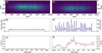
Typical examples of the interference patterns recorded using the SEAHORSE at both the input and output of the fibre are shown in Fig. 2, along with the corresponding temporal dynamics of the phase and amplitude extracted from the raw data. The time interval between two consecutive points in each recorded frame is  $\approx 150$ fs. We have recorded $N=3000$ frames similar to the one displayed in Fig. 2. In order to compare the experimentally measured density of states (DOS) with the theoretical prediction given by Eq. (3), we normalise each experimental frame using the following relations:
 \begin{equation}
\psi=\frac{A}{\sqrt{P_0}},\qquad
z=\frac{1}{2}\gamma \langle P_0\rangle \,z_{lab},\qquad t=\sqrt{\frac{\gamma \langle P_0\rangle }{\beta_2}} \,t_{lab}\, ,
\end{equation}
\begin{equation}
\psi=\frac{A}{\sqrt{P_0}},\qquad
z=\frac{1}{2}\gamma \langle P_0\rangle \,z_{lab},\qquad t=\sqrt{\frac{\gamma \langle P_0\rangle }{\beta_2}} \,t_{lab}\, ,
\end{equation}where  $t_{lab}$, $A(t_{lab})$, $P_0$, $\gamma$ and $\beta_2$ are expressed in physical units, while $\psi$, $z$ and $t$ are dimensionless normalised quantities. Here, $A$ is the slowly varying envelope of the electric field, defined such that $|A|^2$ corresponds to the optical power; $t_{lab}$ is the time, $z_{lab}=1$km is the physical propagation distance in the fibre, $\gamma = 1.3$ W $^{-1}$km $^{-1}$ is the Kerr nonlinearity coefficient and $\beta_2 = -22$ ps $^2$km $^{-1}$ is the group velocity dispersion at the signal wavelength (1550 nm). $P_0$ denotes the optical power averaged over the recorded temporal window. $P_0$ exhibits slight fluctuations from one recorded frame to another (see Appendix A), and $\langle P_0 \rangle$ represents the mean value of $P_0$ averaged over all experimental realisations ( $N = \text{3000}$). All experiments were performed in a single-mode fibre with a physical length of $L_{lab}=1$km. We call $L_{nl}=1/(\gamma\langle P_0\rangle)$. To explore different effective propagation distances $L_{lab}/L_{nl}$, we conducted experiments for several values of $\langle P_0 \rangle$. We have used values of $P_0$ ranking from $3$W to $6$W, which correspond to effective length of propagation ranking from $L_{lab}\approx 4 L_{nl}$ to $L_{lab}\approx 8 L_{nl}$.
Typical intensity and phase dynamics recorded using the SEAHORSE technique (physical units). The left column shows the initial optical field launched into the fibre, while the right column displays the fully developed modulation instability (MI) observed at the fibre output ( $\langle P_0\rangle=6.1$W, $L_{lab}=1$km). The raw SEAHORSE output consists of 2D fringe patterns from interference. (a,d) Raw interferometric data recorded over a temporal window of duration $T_0 \sim 175$ ps. Data processing allows for the reconstruction of the ultrafast temporal dynamics of both the phase and amplitude of the optical field in physical units: (b,e) intensity profiles at the input and output of the fibre, respectively; (c,f) corresponding phase profiles.

Typical examples of the recorded temporal dynamics of both the phase (in red) and power  $|\psi(t)|^2$ (in blue) are shown in Fig. 3. Figure 3(a) was recorded at the input of the fibre, while Figs. 3(b)–(d) were recorded at the output for three different values of the $L_{nl}$. The early development of modulation instability is observed in Fig. 3(b), arising from the nonlinear propagation of a condensate initially perturbed by weak noise, as shown in Fig. 3(a). For larger effective propagation distances, characteristic coherent structures associated with spontaneous MI appear, as illustrated in Fig. 3(c,d).
Single-shot experimental measurements of the phase and amplitude of complex optical fields using the SEAHORSE technique (normalised units). The intensity  $|\psi|^2$, time $t$ and propagation distance $L$ are normalised according to Eq. (4). Normalised intensity (blue) and phase (red) profiles are shown. (a) Complex optical field at the fibre input (initial condition). (b–d) Complex optical fields after propagation through a 1 km single-mode fibre (SMF28), with $L_{lab} = 1$ km. The average injected powers are: (b) 3.05 W ( $L_{lab} \approx 4L_{nl}$), (c) 3.85 W ( $L_{lab} \approx 5L_{nl}$) and (d) 6.1 W ( $L_{lab} \approx 8L_{nl}$).

3.2. Measurement of the density of states (DOS)
Inverse Scattering Transform (IST) – Knowing the full nonlinear field (phase and amplitude)  $\psi(z=L,t)$, the discrete IST spectrum is easily extracted by using the Fourier collocation algorithm described in ref. [Reference Yang53]. For each numerical and experimental realisation, we compute the discrete (IST) spectrum.
Within the framework of the Inverse Scattering Transform (IST), the field  $\psi(z=L,t)$ recorded at the fibre output is associated with the Zakharov–Shabat spectral problem [Reference Yang53], which takes the form of a non-self-adjoint eigenvalue equation:
 \begin{equation}
\widehat{\boldsymbol{\mathcal{L}}} {\boldsymbol{\Phi}} = \lambda {\boldsymbol{\Phi}} ,\qquad
\widehat{\boldsymbol{\mathcal{L}}} =
\begin{pmatrix}
- i \partial_t & -i \psi \\ - i \psi^* & i \partial_t \\
\end{pmatrix}
\end{equation}
\begin{equation}
\widehat{\boldsymbol{\mathcal{L}}} {\boldsymbol{\Phi}} = \lambda {\boldsymbol{\Phi}} ,\qquad
\widehat{\boldsymbol{\mathcal{L}}} =
\begin{pmatrix}
- i \partial_t & -i \psi \\ - i \psi^* & i \partial_t \\
\end{pmatrix}
\end{equation} Here,  $\boldsymbol{\Phi}(t,\lambda)$ is a vector-valued eigenfunction, and $\lambda \in \mathbb{C}$ denotes the spectral parameter. The set of complex eigenvalues $\lambda_j = \xi_j + i \eta_j$ obtained from this equation constitutes the discrete spectrum and provides a spectral fingerprint of the solitonic content of the field. In the context of soliton gases, each eigenvalue $\lambda_j$ corresponds to a single soliton, with its real and imaginary parts ( $\xi_j$, $\eta_j$) determining the free soliton’s velocity and amplitude, respectively. A key feature of integrable dynamics governed by Eq. (1) is that the spectrum remains invariant under evolution – this is the property of isospectrality.
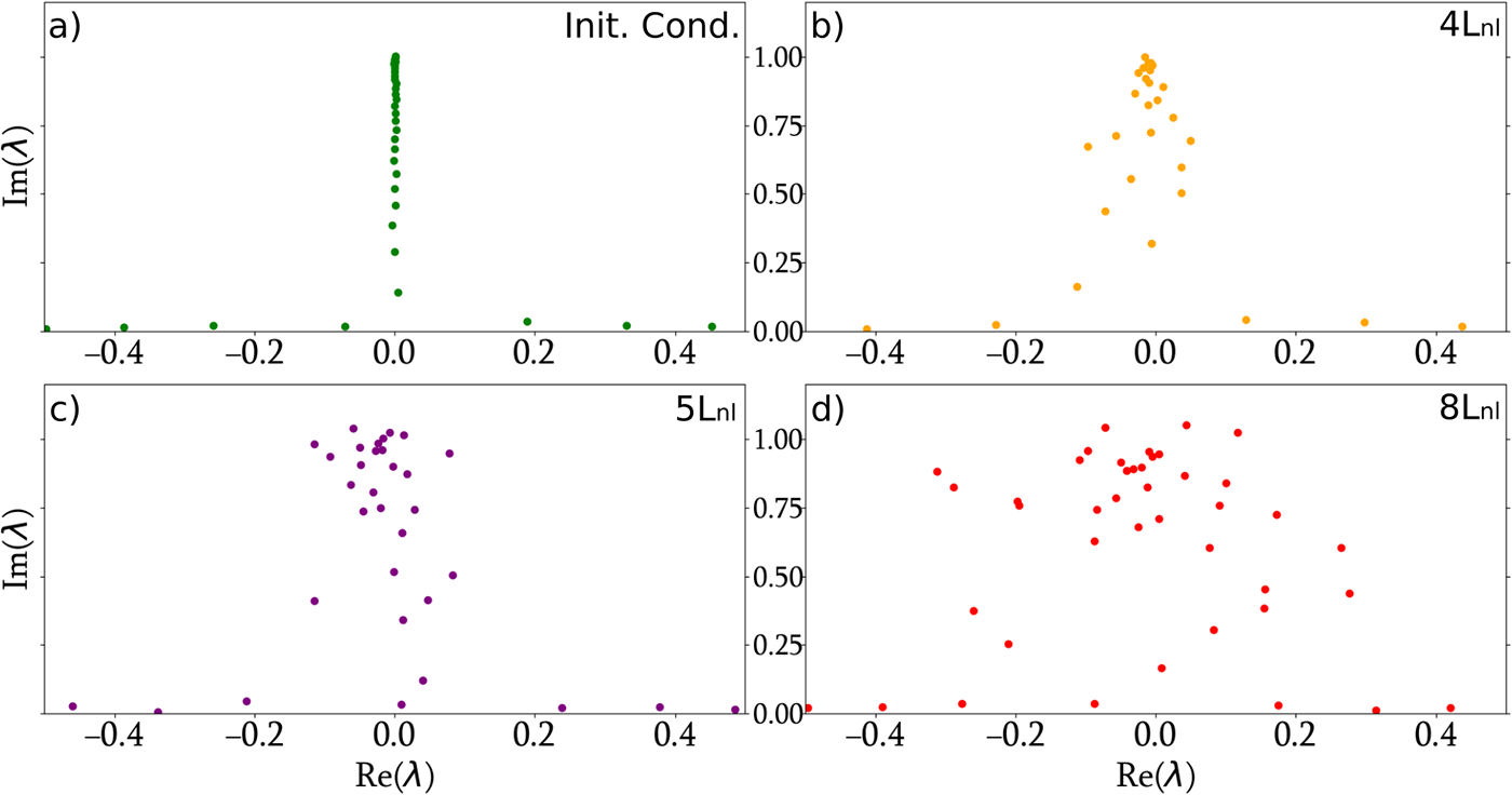
To compute the discrete IST spectrum of the optical soliton gas, we apply the Fourier collocation method (as detailed in [Reference Yang53]) to the experimentally measured, normalised complex field  $\psi$. This numerical procedure yields a set of several tens of discrete eigenvalues $\lambda_j$, all confined to a bounded region of the upper half of the complex plane. The IST spectra corresponding to the fields shown in Fig. 3 are presented in Fig. 4. As expected, for the recorded initial condition ( $z = 0$), which corresponds to a flat, box-shaped pulse with a uniform phase, all eigenvalues lie almost entirely along the imaginary axis ( $\xi_i = 0$), which is consistent with the findings of [Reference Gelash, Agafontsev, Zakharov, El, Randoux and Suret26]. In contrast, one immediately observes deviations from perfect isospectrality in the experimental data: the eigenvalues exhibit a noticeable spread around the imaginary axis, with $\xi_i \ne 0$. Furthermore, the region occupied by the eigenvalues in the complex plane broadens as the effective propagation distance $L=\frac{1}{2}L_{lab}/L_{nl}$ increases. We will discuss later the nature of the higher-order effects responsible for the breaking of integrability in the experiments.
Discrete IST spectra corresponding to the fields shown in Fig. 3. (a) IST spectrum of the initial box-shaped field prior to propagation, corresponding to Fig. 3(a). (b–d) IST spectra associated with the propagated fields shown in Fig. 3(b–d), respectively. The injected average powers are: (b)  $\langle P_0\rangle=3.05$ W ( $L_{lab}\approx 4L_{nl}$), (c) $\langle P_0\rangle=3.85$ W ( $L_{lab}\approx 5L_{nl}$) and (d) $\langle P_0\rangle=6.1$ W ( $L_{lab}\approx 8L_{nl}$).

To investigate the soliton gas and to calculate the DOS, we recorded numerous experimental realisations using different initial conditions, each consisting of a box-shaped pulse with small added noise. The density of states (DOS) is computed by averaging the IST spectra over a large ensemble of  $3000$ realisations. As mentioned earlier, for each realisation, the observation window $T_0$ is much shorter than the full pulse duration $T_{exp}$ and the recorded central portion of the pulse remains extremely flat. Consequently, the soliton gas under investigation can be regarded as homogeneous, and the DOS $f(\lambda, L, t)$ at the normalised propagation distance $z=L$ may be considered independent of $t$, i.e., $f(\lambda, L, t) = f(\lambda, L)$.
The density of states (DOS)  $f(\lambda; L)$, with $\lambda = \xi + i \eta$, is defined such that $f\, d\xi\, d\eta\, dt$ gives the number of solitons in a portion of the soliton gas with spectral parameter $\lambda \in [\xi, \xi + d\xi] \times [\eta, \eta + d\eta]$, within a temporal interval $[t, t + dt]$, at the output of the fibre $z = L$. The probability density function $\phi(\lambda)$ in the complex plane is estimated from the full ensemble of experimental realisations. The DOS is then obtained as $f(\lambda) = \phi(\lambda) / T_0$.
Due to the breaking of integrability in the experimental system, the DOS exhibits a dependence on the propagation distance  $L$ (see Fig. 5). Specifically, we observe both a broadening of the distribution around the imaginary axis and, importantly, the emergence of an asymmetric shape: the DOS is no longer an even function of the real part $\xi_i$.
2D density plots of IST eigenvalues in the complex plane. The colour maps represent the base-10 logarithm of the probability density function (DOS) of the discrete IST eigenvalues  $\lambda$, with $\text{Re}(\lambda)$ on the horizontal axis and $\text{Im}(\lambda)$ on the vertical axis. The first row corresponds to experimental measurements (EXP). Other rows correspond to different models [see Eq. (6)]: NLSE simulations with linear losses only (NLSE), with losses and third-order dispersion (NLSE2) and with losses, third-order dispersion and stimulated Raman scattering (NLSE3). Column (a) shows the initial condition, i.e., before propagation. Columns (b–d) show the DOS after propagation through 1 km of single-mode fibre, for three different input powers: (b) $P_0 = 3.05$ W ( $L_{lab} \approx 4L_\mathrm{nl}$ i.e. $L\approx 2$), (c) $P_0 = 3.85$ W ( $L_{lab} \approx 5L_\mathrm{nl}$ i.e. $L\approx 2.5$)), (d) $P_0 = 6.1$ W ( $L_{lab} \approx 8L_\mathrm{nl}$ i.e. $L\approx 4$)).

Breaking of integrability. – The measurement of the DOS reveals that the nonlinear propagation of light pulses in our experiments is not fully captured by the integrable 1D-NLSE given in Eq. (1). In particular, the gradual evolution of the DOS with the effective propagation distance  $L$ indicates the presence of higher-order effects that break integrability of the wave system. Nonlinear pulse propagation in single-mode optical fibres has been extensively studied, and it is well described not by the integrable 1D-NLSE (Eq. (1)) but by a generalised nonlinear Schrödinger equation (gNLSE) that includes linear losses, higher-order dispersion and stimulated Raman scattering (SRS).
The experimental parameters used in [Reference Fache, Copie, Suret and Randoux23] differ significantly from those in the present work: in [Reference Fache, Copie, Suret and Randoux23], the mean optical power is much lower, the soliton durations are much longer and integrability is primarily broken by linear losses. As a result, the DOS reported in [Reference Fache, Copie, Suret and Randoux23] exhibits a symmetric spreading around the imaginary axis. Here, the observed asymmetry of the DOS with respect to the real part  $\xi$ suggests a breaking of time-reversal symmetry. This asymmetry is consistent with the well-known self-frequency shift induced by SRS – a nonlinear high order effect – which causes an adiabatic redshift of the soliton’s central frequency and, consequently, a modification of its group velocity [Reference Gordon29, Reference Mitschke, Mahnke and Hause34, Reference Okamawari, Hasegawa and Kodama36]. Since the real part of the IST eigenvalue is proportional to the soliton’s free velocity, Raman scattering is expected to play a significant role in the asymmetry of the measured DOS.
In the next section, we present numerical simulations of the generalised NLSE and investigate the individual influence of each additional physical effect.
4. Numerical simulations
In this section, we present numerical simulations based on the generalised nonlinear Schrödinger equation (gNLSE), expressed in physical units as:

where  $\alpha=2.25.10^{-2}$km $^{-1}$ is the linear loss coefficient, $\beta_3 = 10^{3}$ ps $^3$km $^{-1}$ is the third-order dispersion coefficient and $T_r = 3.10^{-3}$ ps is the Raman response time in silica.
We first generate a large ensemble of  $1000$ realisations of initial conditions, consisting of a constant amplitude field $A$ perturbed by random noise, defined over a temporal window of duration $T_{PBC} \approx 250$ ps with periodic boundary conditions. The evolution of the field $A(z, t)$ is computed using a standard adaptive step-size pseudo-spectral method [Reference Randoux, Walczak, Onorato and Suret40]. The DOS is then calculated following the same procedure as in the experiment. In particular, since in the experiment the observation window $T_0$ is much shorter than the full pulse duration $T_{exp}$, we replicate this constraint in the simulations by extracting a temporal window of duration $T_0 \approx 175$ ps from the full periodic domain $T_{PBC}$ prior to computing the IST spectrum. In all simulations, we also incorporate the fluctuations of the input pulse power observed in the experiments (see Sec. A for details).
We perform simulations under three configurations, each including an increasing number of perturbative terms in Eq. (6): (i) NLSE with losses only, (ii) NLSE with losses and third-order dispersion (NLSE2) and (iii) the full model including losses, third-order dispersion and stimulated Raman scattering (NLSE3). The corresponding DOS for these three cases are reported in Fig. 5.
For finite propagation distances  $L \gt 0$, the dynamics of modulation instability (MI) becomes increasingly intricate and the combined effects of losses, windowing and fluctuations (see Sec. A) lead to a mild but symmetric broadening of the DOS around the imaginary axis (see second row of Fig. 5). The addition of third-order dispersion further amplifies this broadening, which becomes non-uniform along the imaginary direction.
The most prominent deformation of the DOS is induced by SRS. In this regime, the DOS becomes asymmetric: the real part  $\xi$ of eigenvalues with large imaginary part $\eta$ shifts towards negative values, while those with small $\eta$ are shifted towards positive values. This behaviour is nontrivial and results from the collective interactions within the soliton gas. Indeed, an isolated soliton is expected to undergo a self-frequency shift towards lower frequencies, corresponding to negative values of $\xi$ [Reference Agrawal5]. This well-known effect likely explains the trend observed for eigenvalues with large $\eta$. However, the counterintuitive behaviour of eigenvalues with small imaginary part can only be understood by considering the many-body interactions among solitons in the SG [Reference Okamawari, Hasegawa and Kodama36].
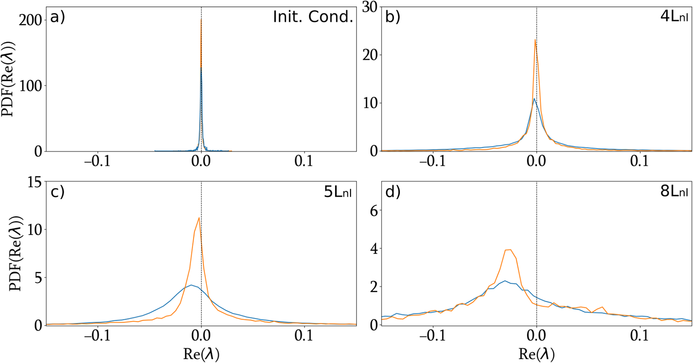
To enable a quantitative comparison between experiments and numerical simulations, we plot in Fig. 6 (resp. Figure 7) the probability density function (PDF) of the real (resp. imaginary) part of the IST eigenvalues, as obtained from the generalised NLSE (6) including all effects, and from experimental data. One observes that the numerical simulations reproduce the main features seen in the experiments: a comparable broadening of the probability density function (PDF) of the real part of the eigenvalues, and a mean shift of the distribution towards negative values of  $\xi$ as the propagation distance $L$ increases. For the imaginary part, in the integrable case, we expect a Weyl-type distribution (see Ref. [Reference Gelash, Agafontsev, Zakharov, El, Randoux and Suret26]), shown as a dashed line in Fig. 7. Due to the finite temporal window used for the IST computation, the eigenvalue spectrum for the initial box-like condition is discretised in a non-uniform manner, as is well known for the box [Reference Gelash, Agafontsev, Zakharov, El, Randoux and Suret26]. As the dynamics become more complex ( $z \ne 0$), the PDF of $\eta$ extracted from both simulations and experiments evolves into a smooth function. Notably, higher-order effects tend to smooth out the distribution around $\eta = 1$, whereas the theoretical Weyl distribution diverges at $\eta = 1$ (see Eq. (3)).
Probability density function (PDF) of the real part of the IST eigenvalues,  $PDF(\text{Re}(\lambda))$, as a function of $\xi = \text{Re}(\lambda)$. Experimental results (blue) are compared with numerical simulations (orange) based on the full NLSE3 model (6), which includes linear losses, third-order dispersion and stimulated Raman scattering. (a) PDFs for the initial condition corresponding to the box-shaped potential before propagation in the optical fibre. (b–d) PDFs obtained after propagation through 1 km of single-mode fibre (SMF28), shown for both experimental measurements (blue) and numerical simulations (orange). The injected average powers are: (b) $P_0 = 3.05$ W ( $L_{\mathrm{lab}}\approx4L_{\mathrm{nl}}$), (c) $P_0 = 3.85$ W ( $L_\mathrm{lab}=5L_{\mathrm{nl}}$), (d) $P_0 = 6.1$ W ( $L_\mathrm{lab}=8L_{\mathrm{nl}}$).

Probability density function (PDF) of the imaginary part of the IST eigenvalues,  $PDF(\text{Im}(\lambda))$, as a function of $\eta = \text{Im}(\lambda)$. Experimental data (blue) are compared with numerical simulations (orange) based on the full NLSE3 model, which includes linear losses, third-order dispersion and stimulated Raman scattering. The dashed line represents the Weyl’s distribution given by Eq. (3). (a) PDFs for the initial condition corresponding to the box-shaped potential before propagation in the optical fibre. (b–d) PDFs obtained after propagation through 1 km of single-mode fibre (SMF28), shown for both experimental measurements (blue) and numerical simulations (orange). The injected average powers are: (b) $P_0 = 3.05$ W ( $L_\mathrm{lab}\approx4L_{\mathrm{nl}}$), (c) $P_0 = 3.85$ W ( $L_\mathrm{lab}=5L_{\mathrm{nl}}$), (d) $P_0 = 6.1$ W ( $L_\mathrm{lab}=8L_{\mathrm{nl}}$).

Our numerical simulations based on the gNLSE combined with fluctuations in the input pulse power, qualitatively reproduce the experimental observations. However, we note some quantitative discrepancies between the PDFs of  $\xi$ and $\eta$ obtained from simulations and those extracted from experimental data. We currently do not have a clear explanation for these differences. It is likely that the parameter fluctuations in the experiments – particularly the variations in the input power – are not fully captured by our minimal fluctuation model. Despite these discrepancies, our key conclusion remains: stimulated Raman scattering (SRS) plays a central role in the adiabatic evolution of the DOS during the propagation and is responsible for the characteristic asymmetry in the DOS, which manifests as nonzero real parts of the IST eigenvalues.
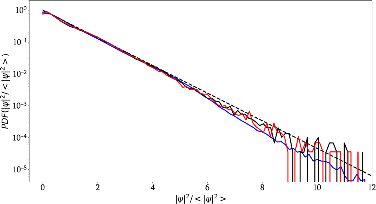
Notably, within the parameter range explored here, the influence of stimulated Raman scattering (SRS) on the statistics of  $ |\psi|^{2} $ is not discernible. It is well established that the long-time evolution of modulation instability in integrable 1D NLSE systems yields an exponential probability density function (PDF) for $ |\psi|^{2} $ (see [Reference Agafontsev and Zakharov4, Reference Kraych, Agafontsev, Randoux and Suret32]). Our experiments and numerical simulations show that the PDF remains very close to this exponential law even in the presence of SRS (see Appendix B). Remarkably, the change in the density of states (DOS) in the IST plane appears more sensitive than any measurable change in direct (physical) space. The relationship between statistics and DOS is a highly nontrivial problem and lies beyond the scope of this study [Reference Congy, El, Roberti, Tovbis, Randoux and Suret16].
5. Conclusion
In this work, we have reported the experimental measurement of the density of states (DOS) associated with the noise-induced modulation instability (MI) in optical fibres, using the full-field reconstruction enabled by the SEAHORSE technique. Our results confirm that in the early stage of MI, the solitonic content of the wavefield is well-described by a soliton gas (SG) characterised by the Weyl distribution of IST eigenvalues, as predicted theoretically. At later stages, we observe a progressive departure from isospectrality, manifested by a broadening and asymmetry of the DOS. By comparing experiments with numerical simulations of the generalised nonlinear Schrödinger equation (gNLSE), we have shown that the stimulated Raman scattering (SRS) plays a central role in this adiabatic deformation of the soliton spectrum.
These results open important theoretical questions. In particular, a major challenge is to develop a kinetic theory for soliton gases beyond integrability, accounting for perturbative effects such as SRS. This would require extending the soliton gas kinetic equation (or, equivalently, the framework of generalised hydrodynamics) to include explicit non-conservative terms (in particular SRS) that break time-reversal symmetry and induce spectral evolution. Our experiments provide a unique benchmark for such theoretical developments and suggest that new classes of hydrodynamic equations – describing the slow evolution of the spectral DOS under weak integrability-breaking perturbations – could be derived. These results pave the way for a more comprehensive statistical theory of out-of-equilibrium nonlinear wave systems beyond the idealised integrable case.
Data availability statement
Data available on reasonable request.
Acknowledgments
We thank Dmitry Agafontsev, Thibault Congy, Andrey Gelash and Alexander Tovbis for their collaboration and the discussions we have had over the years on SG-related topics. The authors would like to thank the Isaac Newton Institute for Mathematical Sciences, Cambridge, for support and hospitality during the programme Emergent phenomena in nonlinear dispersive waves, where work on this paper was undertaken. This work was supported by EPSRC grant EP/V521929/1. FC, SR and PS would like to thank the Centre d’Etudes et de Recherche Lasers et Application (CERLA) for technical support.
Author contributions
Conceptualisation: P.S., S.R., F.C. and A.L. Methodology: all the authors have contributed equally. Data curation: A.L. and P.S. Data visualisation: A.L. Writing original draft: P.S. and A.L. All authors approved the final submitted draft.
Funding statement
This work has been partially supported by the Agence Nationale de la Recherche through the SOGOOD (ANR-21-CE30-0061) projects, the Ministry of Higher Education and Research, Hauts de France council and European Regional Development Fund (ERDF) through the Hauts de France Regional Research Council and the European Regional Development Fund (ERDF) through the Contrat de Projets Etat- Région (CPER Photonics for Society P4S). The authors acknowledge the support of the CDP C2EMPI, as well as the French State under the France-2030 programme, the University of Lille, the Initiative of Excellence of the University of Lille, the European Metropolis of Lille for their funding and support of the R-CDP-24-004-C2EMPI project.
Competing interests
None.
Appendix A. Influence of input power fluctuations on the measurement of the DOS
As discussed in Section 3.1, we inject a  $T_{exp} = 36$ ns-long optical pulse into a 1 km-long single-mode fibre, where modulation instability (MI) develops. From shot to shot, the average optical power of the pulse exhibits slight fluctuations, modelled as $P_0 = \langle P_0 \rangle (1 + \eta)$. Similarly, the pump pulse power fluctuates as $P_{\mathrm{pump}} = \langle P_{\mathrm{pump}} \rangle (1 + \eta_p)$.
In the SEAHORSE technique, the measured signal is proportional to the product of the pump and signal powers, and therefore fluctuates as  $P_{\mathrm{meas}} \propto \langle P_0 \rangle \langle P_{\mathrm{pump}} \rangle (1 + \eta)(1 + \eta_p)$. Assuming that $\eta$ and $\eta_p$ are small, we approximate $(1 + \eta)(1 + \eta_p) \simeq 1 + \eta + \eta_p$, so that the measured power for a single realisation (integrated over one single frame) becomes:
 \begin{equation*}
P_{\mathrm{meas}} \propto \langle P_0 \rangle (1 + \eta + \eta_p).
\end{equation*}
\begin{equation*}
P_{\mathrm{meas}} \propto \langle P_0 \rangle (1 + \eta + \eta_p).
\end{equation*} $\langle P_0\rangle$ is measured by using a standard (slow) powermeter. Moreover, we independently measure the statistical distributions of $\eta$ and $\eta_p$ using a standard photodetector. However, due to the lack of synchronisation between the measurements of $\eta$ and $\eta_p$, it is not possible to determine the exact value of $\eta + \eta_p$ for each individual realisation. Consequently, the precise input power $P_0$ for each SEAHORSE shot remains unknown, introducing a small uncertainty in the normalisation of the experimental data (as described in Eq. (4)).
To assess the impact of this uncertainty, we have investigated a minimal model in which we assume  $\eta_p=0$. More precisely, we performed numerical simulations of the nonlinear Schrödinger equation (1D-NLSE), incorporating input power $P_0$ fluctuations matching the experimental distribution of $\eta$( Gaussian with $\sigma \approx 0.058$). We computed the discrete IST spectra over large ensembles of simulated realisations under two scenarios:
• Ideal normalization: normalisation using the exact value of $P_0$ for both the field and the time axes.
• Experimental-like normalization: normalisation using
$P_0$ for the field but
$\langle P_0 \rangle$ for the time axis (this normalisation is used in the experimental data analysis reported in the paper)


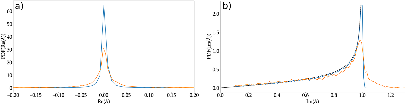
The results, shown in Fig. A1, indicate that imperfect normalisation (as occurs in the experiment) introduces only minor distortions in the IST spectrum. The imaginary part exhibits a slight redistribution of eigenvalues, with a reduced peak in the Weyl distribution and the appearance of a small tail beyond  $\text{Im}(\lambda) = 1$. The real part shows a modest broadening around zero. Overall, these effects remain weak and do not qualitatively affect the interpretation of the experimental spectra.
Impact of fluctuations on the IST spectrum (numerical simulations). The Probability Density Functions (PDF) of (a) the real part and (b) the imaginary part of the IST eigenvalues are shown for the two possible normalisations: ideal normalisation (blue) and experimental-like normalisation (orange). Simulations include input power fluctuations (Gaussian distribution with root mean square  $\sigma \approx 0.058$). $\langle P_0\rangle=6$ W.

Appendix B. Probability density functions of optical power
The statistics of modulation instability (MI) have been extensively studied, both theoretically [Reference Agafontsev and Zakharov4, Reference Gelash, Agafontsev, Zakharov, El, Randoux and Suret26] and experimentally [Reference Kraych, Agafontsev, Randoux and Suret32]. A key result is that the long-time evolution of MI in the 1D NLSE is characterised by an exponential probability density function (PDF) for the intensity  $|\psi|^2$ [Reference Agafontsev and Zakharov4, Reference Gelash, Agafontsev, Zakharov, El, Randoux and Suret26, Reference Kraych, Agafontsev, Randoux and Suret32]. Here, we report the PDFs of the optical power measured at the fibre output in experiments and obtained from numerical simulations, for the largest effective nonlinearity ( $L_{lab}=8L_{nl}$).
One observes that breaking integrability through third-order dispersion and stimulated Raman scattering (SRS) (Eq. (6)) does not significantly alter the statistics (see Fig. B1). For the finite propagation distance  $L_{lab}=8\,L_{nl}$, the stationary statistical state is not fully reached, and the PDF of the normalised intensity $|\psi|^{2}/\langle |\psi|^{2}\rangle$ lies slightly below the exponential law. The experimentally measured PDF exhibits a tail marginally lighter than the one obtained numerically. This small discrepancy can be attributed to uncertainties in parameter estimation and to the finite detection bandwidth [Reference Tikan, Bielawski, Szwaj, Randoux and Suret49].
Probability density function (PDF) of the optical power. The PDF of  $ \frac{|\psi|^{2}}{\langle |\psi|^{2} \rangle} $ measured experimentally at the fibre output is shown in blue. The PDF computed from numerical simulations of the gNLSE with losses only (‘NLSE’ in Eq. (6)) is shown in black. The PDF computed from simulations of the full gNLSE including all higher-order terms (‘NLSE2+NLSE3’ in Eq. (6)) is shown in red. The dashed line denotes the exponential reference $\exp (-|\psi|^{2}/\langle |\psi|^{2} \rangle$).












 Open access

