


1. Introduction
Over the past two decades, Generative Design (GD) has emerged as a promising paradigm in engineering and industrial design. Its rise coincides with increasing demands for efficient product development, sustainable solutions, and the integration of advanced computational tools into design practice. At its core, GD seeks to automate aspects of the design process, enabling designers and engineers to explore extensive design spaces and discover solutions that would be difficult, if not impossible, to obtain manually.
The concept of GD has evolved significantly over time. In its earliest formulation in 2003, GD was described as a workflow aimed at automatically creating parts based on predefined parameters (Reference GraesslerGraessler, 2003). Since manual modelling of components is highly time-consuming, the generative approach was primarily valued for its potential to reduce effort through a high degree of automation. By 2022, the emphasis had shifted towards algorithmic design synthesis. GD was increasingly defined as a process in which algorithms generate designs either through explicit programming or through implicit learning. This framing highlighted the role of computational intelligence in synthesising design alternatives and broadened the understanding of GD beyond rule-based automation (Reference Regenwetter, Nobari and AhmedRegenwetter et al., 2022).
Most Recently, GD was further refined as an integrated approach for both the autonomous generation and the evaluation of designs. Algorithms were now understood to account for user-defined boundary conditions such as materials, manufacturing processes, loads, and supports. This definition marked a step towards industrial applicability, as it acknowledged the necessity of aligning algorithmically generated outcomes with real-world engineering requirements (Reference Gerhard, Köring, Neges, Noël, Nyffenegger, Rivest and BourasGerhard et al., 2023).
Building on these perspectives, we define GD in this work as a process in which product developers translate diverse and complex requirements for components into a form suitable GD tool. Supported by methods of machine learning, a large variety of design variants are produced from these specifications. The aim is to span broad solution spaces through well-defined requirements and relevant information, thereby enabling the discovery of innovative solutions rather than merely refining existing ones. The underlying software is based on optimisation algorithms, machine learning techniques, and physics-based simulations.
So, GD is fundamentally underpinned by optimisation algorithms and machine learning techniques, which rely on physics-based simulations. A particularly noteworthy foundation is topology optimisation (Reference Bendsøe and SigmundBendsøe & Sigmund, 2004), the result of which is a mathematically optimal structure for given boundary conditions. Among these, density-based methods (Reference BendsøeBendsøe, 1989) are the oldest and remain the most widely applied due to their simplicity, flexibility, and robustness. More recent alternatives include level-set methods, which have not yet gained widespread adoption due to their more complex implementation requirements (Reference Wang, Zhao, Zhou, Sigmund and ZhangWang et al., 2021). The principle task of machine learning algorithms within GD is to navigate design spaces, propose candidate designs and classify alternatives (Reference Garcia and LeitãoGarcia & Leitão, 2022). In doing so, the aim is to span extensive solution spaces defined by requirements and relevant information, thereby fostering the generation of innovative solutions rather than continuous incremental refinement of existing ones (Reference Gerhard, Köring, Neges, Noël, Nyffenegger, Rivest and BourasGerhard et al., 2023). Deep generative models are particularly relevant in this context, including feedforward neural networks, generative adversarial networks, variational autoencoders, and, to some extent, deep reinforcement learning frameworks (Reference Regenwetter, Nobari and AhmedRegenwetter et al., 2022). These methods are applied with the objective of identifying the most suitable design proposals. They can also be employed to translate requirements expressed in natural language into machine-readable formats, thereby reducing the manual effort associated with modelling (Reference Gräßler, Preuß, Brandt and MohrGräßler et al., 2023). Recent work has even demonstrated neural network–assisted topology optimisation that does not rely on pre-computed optimised parts as training data (Reference Halle, Campanile and HasseHalle et al., 2021). Nevertheless, topology optimisation typically produces geometries with highly complex and filigree features that cannot easily be manufactured using conventional processes. Even in the case of additive manufacturing, manual post-processing is often required to reduce or eliminate support structures (Reference Rosnitschek, Hentschel, Siegel, Kleinschrodt, Zimmermann, Alber-Laukant and RiegRosnitschek et al., 2021).
Organizing requirements and constraints along the process helps identify objectives and constraints that align with the capabilities of the software tools (Reference Soika, Endress, Schenk and ZimmermannSoika et al., 2025). Despite the mentioned advances, a persistent gap remains between the conceptual potential of GD and the practical capabilities of existing commercial tools. While GD software promises broad applicability, many constraints relevant to engineers, such as wall thickness, anisotropy, or manufacturing-specific rules, are not directly implemented. Designers are therefore required to identify and apply workarounds, such as controlling minimum feature size indirectly by adjusting mesh parameters. These practices are critical for bridging the gap between software functionality and industrial requirements, yet they remain underexplored in both academic literature and design methodology discourse.
Thus, the focus of this paper is to investigate how two commercially available GD tools can be applied to achieve manufacturable outcomes for Design for Additive Casting (DfAC). Rather than questioning the overall capability of these tools, we explore how PTC Creo Generative Topology Optimisation (GTO) and Altair Inspire 2025.1 support the integration of manufacturing-relevant aspects, when only minimal restrictions need to be imposed, as is often the case in DfAC. We examine how indirect approaches can be used to realise constraints that are not explicitly available, while maintaining a broad design space and leveraging the considerable capabilities that both tools already provide. Widening the usability of already existing tools, overcoming barriers by generalizing problems. The contribution is methodological, by identifying designer-level strategies that bridge the gap between available constraint sets and industrial manufacturability requirements. Consequently, we are analysing how to improve the quality or usability of single design proposal withing the variety of designs generated.
Therefore, the purpose of this paper is to advance the methodological discussion on GD and to provide industry-relevant guidance for practitioners seeking to integrate commercial tools effectively into their workflows, despite inherent limitations in constraint handling.
To address this research question, the paper is structured as follows. Section 2 outlines the materials and methods, beginning with a use case in which a deflection lever is optimised using generative design for additive casting (Section 2.1). The specific design objectives are defined in Section 2.2, followed by the description of the finite-element-based verification setup in Section 2.3. Section 3 presents the results and discussion. Particular attention is given to strategies for ensuring pre-defined wall thickness (Section 3.1) and to the consideration of cooling channels (Section 3.2). Finally, Section 4 concludes the paper by summarising the key findings and outlining implications for the application of commercial GD tools in an industrial context.
2. Materials and methods
2.1. Use case: optimizing a deflection lever using generative design for additive casting
Otto Bihler Maschinenfabrik GmbH & Co. KG is one of the world’s leading system suppliers of stamping, bending, and assembly technology. Bihler’s mechanical design team collaborated with the authors to investigate the opportunity for improvement of an existing machine component using GD. The selected component, a deflection lever, serves as a representative industrial use case, combining high mechanical load requirements with geometric and manufacturing constraints typical of complex tooling systems. The objective was to explore how commercial GD tools can be applied to re-engineer such components for additive casting while meeting structural performance targets and manufacturability criteria. As shown in Figure 1(a), the analysed deflection lever forms part of the middle stamp deflection subassembly, which operates within an industrial stamping machine. The deflection lever rotates around a fixed centre bearing, transmitting the linear movement of the upper actuator into the horizontal movement of the middle stamp (Figure 1c). During production, the deflection lever rotates up to 250 times per minute, thus an optimized component (Figure 1(c)) is promising for minimising the operation energy and maximise equipment efficiency.
(a): Middle stamp deflection subassembly; (b): Currently milled component with load requirements; (c): Design optimised using generative design

Figure 1 Long description
Panel A: A diagram of the middle stamp deflection subassembly, showing the mechanical structure and components involved. Panel B: A diagram of a currently milled component with load requirements, highlighting the areas where forces are applied. Panel C: A diagram of a design optimized using generative design, demonstrating the final optimized structure.
The original part is milled from a 16MnCr5 steel block, with a mass of 1.78 kg and an inertia moment of 0.010594 kg m2 around the rotation centre. Under a maximum load of
 $${F_1}$$
= 8,900 N the maximum deformation in terms of length variation between the two rotating bearings must not exceed 0.05 mm to ensure a proper stamping process accuracy. The lubricant of the bearings is fed through several M5 screwed fittings (see Figure 2(a) and Figure 2(b)) from a central lubrication unit. One fitting (A) is screwed directly to the housing of the upper bearing, a second one (B) is connected to a 120 mm long internal channel leading to the bottom bearing and the third and fourth fittings (C) are joined through a 90° internal channel to redirect the lubrication tube to a further component properly. Additionally, two M4 screws (D) attach a small sheet metal tube support to the deflection lever (Figure 2(c)).
$${F_1}$$
= 8,900 N the maximum deformation in terms of length variation between the two rotating bearings must not exceed 0.05 mm to ensure a proper stamping process accuracy. The lubricant of the bearings is fed through several M5 screwed fittings (see Figure 2(a) and Figure 2(b)) from a central lubrication unit. One fitting (A) is screwed directly to the housing of the upper bearing, a second one (B) is connected to a 120 mm long internal channel leading to the bottom bearing and the third and fourth fittings (C) are joined through a 90° internal channel to redirect the lubrication tube to a further component properly. Additionally, two M4 screws (D) attach a small sheet metal tube support to the deflection lever (Figure 2(c)).
The manufacturing batch of the analysed component is around four to ten parts, with an approximate total yearly order of several dozen components. This makes it also suitable for other manufacturing technologies, such as additive casting (3D printing of sand moulds in combination with casting). This indirect additive manufacturing technique is chosen for producing the component due its design freedom. In addition to reducing manufacturing constraints, this combination of technologies has the potential to reduce production costs per part. To further explore this potential, it has been decided to experimentally validate the production of M4 and M5 threads and the internal lubrication channel directly within the casted part (see Figure 3). The threads will be obtained by casting directly onto coated M4 and M5 screws, which will then be removed. The long internal lubrication channel will be obtained by casting on a pre-formed wire, which will also be removed after the part has cooled down. After initial trials, it is recommended that the wire has a continuous radius to facilitate its subsequent extraction. The M5 thread at the beginning of the long lubrication channel will be obtained using an insert placed inside the sand mould and joined to the final part during casting.
(a): M5 lubrication fittings (A), (B), (C); (b): detail view for lubrication fittings (A), (B), (C); (c): tube support fixed with two M4 screws (D)

The deflection lever constitutes a representative benchmark for evaluating GD workflows under DfAC conditions because it combines multi load paths, functional internal channels, strict deformation limits, and a hybrid manufacturing target combining additive mould and casting. These characteristics are typical for high-performance cast components in tooling systems, making the insights transferable to other complex geometries.
(a) Optimised design including the M4 and M5 screws, the pre-formed wire and the M5 insert, before the casting process (b) cross-section of the part

2.2. Generative Design objectives
The primary optimisation target for the given use case is to reduce the inertia moment to minimise the operation energy and maximise equipment efficiency. Due to the lack of commercial solutions for achieving this target directly, minimising the component mass has been defined as the primary objective to indirectly reduce the inertia moment. To meet the deformation goal and allow for a significant reduction in material, a cast iron material (EN-GJS-600-3) has been chosen. Thanks to the flexibility of additively manufactured sand moulds, some traditional design constraints such as draft angles and undercut limitations can be disregarded. Nevertheless, a minimum wall thickness of around 5 mm is recommended to avoid filling defects during the casting process. Also, a gradual variation in wall thickness is required to minimise casting defects. This can be achieved by adding fillet radii to the designed part. Therefore, we chose to indirectly address the minimisation of the inertia moment by minimising the mass alongside stress and displacement constraints. Thereby, the stress constraint was the material’s yield stress, and the displacement constraint was 0.05 mm.
2.2.1. Defined wall-thickness
The minimum feature size constraint is especially applicable for parts manufactured by casting methods, ensuring that the part can be casted without defects due to small channels and cross sections. Restricting the structural size limits the optimisation algorithm yet guarantees manufacturability of the part. The minimum feature size was set to 5 mm to assure best castability while giving highest flexibility for the optimisation algorithm.
To ensure the representation of a minimum structural size, the mesh must use elements smaller than one third of the defined minimum. Smaller elements also allow for finer overall detail. However, simulation time is largely determined by the chosen element size, requiring a trade-off between detail resolution and computational effort.
2.2.2. Integration of cooling channels
We considered the following guidelines for the optimisation of the deflection lever: (i) the integration of additional functional features such as lubrication channels, mounting points, and machining allowances, and (ii) the geometric adaptation of such features to ensure casting feasibility.
To examine the influence of integration timing, two modelling strategies were implemented:
-
1. Concurrent integration, in which the geometry of lubrication channels was incorporated directly into the optimisation domain; and
-
2. Sequential integration, in which the channels and connection points were added manually after the optimisation process.
For both strategies, the design domain, load cases, and boundary conditions were defined identically. The models were exported as STL meshes and, where applicable, re-imported into the CAD environment for post-processing. To evaluate structural performance and manufacturability, the optimised geometries were later compared in Section 3 with respect to their compliance with casting guidelines and their structural response obtained through finite element analysis (FEA). Preliminary decision guidelines on concurrent or sequential integration are discussed and further explored in Section 3.
2.3. Optimisation setup
We used two commercially available tools for GD, GTO and Altair Inspire. In general, we considered four load cases. Two load cases correspond to the lever in its maximum angular deflection, two load cases to the lever in its minimal angular deflection. In both deflection points the force is once applied to the upper bearing and once to the lower bearing with a circular bearing condition applied to the two remaining bearings, fixing axial displacement (see Figure 4).
While no classical parametric sensitivity study was conducted, the four load cases represent different boundary conditions. Evaluating all designs under all load cases therefore serves as an implicit robustness assessment. Four load cases representing the minimal and maximal angular deflections of the lever with the maximum forces applied to the optimised design

Figure 4 Long description
Panel 1: A diagram of a lever with a load case labeled Load Case 1. The lever is subjected to a force of 8900 N at an angle of 22.90 degrees. Panel 2: A diagram of a lever with a load case labeled Load Case 2. The lever is subjected to a force of 8900 N at an angle of 32.60 degrees. Panel 3: A diagram of a lever with a load case labeled Load Case 3. The lever is subjected to a force of 8900 N at an angle of 95.20 degrees. Panel 4: A diagram of a lever with a load case labeled Load Case 4. The lever is subjected to a force of 8900 N at an angle of 53.20 degrees.
2.3.1. Setup for Generative Topology Optimisation in Creo
With the Generative Topology Optimisation (GTO), Creo offers direct integration of part optimisation into its CAD software. The optimisation setup is comparable to a FEA, or a topology optimisation setup. Every load case is represented by loads and boundary conditions.
In GTO, as well as in TO, preserve bodies must be applied and excluded geometry can be applied. All loads and boundary conditions can only be applied to preserve bodies. Excluded geometry defines regions where no material is allowed, such as other components like shafts, bearings, or oil lines. All bearings and shafts, as well as a simplified geometry of adjacent components, were excluded from the optimisation (see Figure 5).
For all casted levers, a cast iron material (EN-GJS-600-3) was used with a Young’s modulus of 171 GPa and a Poisson’s ratio of 0.275. For the milled lever, a structural steel 16MnCr5 was used with a Young’s modulus of 210 GPa and a Poisson’s ratio of 0.3.
The mass limit for the levers was set to 1.25 kg. For the mass calculation of the finished parts density of 7.13
 $${{{\rm{kg}}}}\over{{{\rm{d}}{{\rm{m}}^3}}}$$
for the EN-GJS-600-3 and 7.85
$${{{\rm{kg}}}}\over{{{\rm{d}}{{\rm{m}}^3}}}$$
for the EN-GJS-600-3 and 7.85
 $${{{{\rm{kg}}}}\over{{{\rm{d}}{{\rm{m}}^3}}}}$$
for 16MnCr5 were used.
$${{{{\rm{kg}}}}\over{{{\rm{d}}{{\rm{m}}^3}}}}$$
for 16MnCr5 were used.
(a) Simplified geometry of adjacent parts; (b) simplified geometry cut in half (exclude geometry in red, preserve geometry in blue and the finished part in grey)

2.3.2. Setup for Generative Design in Altair Inspire
Altair Inspire 2025.1 was used for CAD-integrated topology optimization and subsequent geometry reconstruction. The optimization used the same load cases, boundary conditions, and material properties as described in Section 2.3.1. The cylinders interfacing with the bearings were treated as non-design (preserve) regions, and the design space was defined manually (Figure 6). Supports were applied to the inner cylinder surfaces via rigid couplings (RBE2), loads were considered with flexible couplings (RBE3), which were also used for displacement constraints.
After optimization, the final geometry was reconstructed from the density field by fitting PolyNURBS within Inspire’s post-processing. Functional features (e.g., lubrication channels, connection points and surfaces) were added as required to the redesigned part.
Optimization setup: bearing areas as non-design domains in grey; design-domain in brown. Load, supports and displacement constraint are plotted for load case 2

2.4. Finite-element-based verification
The results were verified with a FEA in OptiStruct 2025 using a 3D small-strain linear-elastic formulation. The domain was discretized with quadratic tetrahedral elements. A mesh-convergence study showed that results were stable once each of the three parts exceeded 40,000 elements. All reported verification results therefore use meshes > 40,000 elements per part.
3. Results and discussion
3.1. Ensuring pre-defined wall-thickness and consideration of cooling channels
In addition to the integration of functional features, the preservation of manufacturable wall thicknesses proved essential for ensuring both structural integrity and casting feasibility. Despite only applying a minimum wall-thickness constraint and no control over the maximum wall-thickness, the optimisation outcomes showed that wall geometries that predominantly fell within the desired range for additive casting were generated. Although this behaviour cannot be explicitly enforced through the existing constraint set, the outcome indicates that the algorithm in both tools used implicitly converges towards thickness values consistent with practical design requirements when suitable boundary conditions are applied. This suggests that even limited constraint control can lead to acceptable manufacturability when the design space and loads are defined carefully. In Altair Inspire, the structure can be redesigned automatically within seconds using the integrated PolyNURBS fitting. Alternatively, a manual redesign can be performed with the manual PolyNURBS fitting tool. Although this approach is more time-consuming, it allows for more precise control of features and constraints such as minimum and maximum wall thicknesses as well as surface transitions. The geometry can also be adjusted after additional features have been integrated, which may be necessary if FEA identifies violated constraints.
Overall, the setup of the GD model, the calculation of the GD solution and manual fitting of the PolyNURBS in Altair Inspire is significantly faster than a complete manual design of the component. This is particularly true because the results meet the requirements much more quickly and there is no need to go through an iterative loop of design and simulation. Manual post-processing and PolyNURBS fitting are not necessary in Creo GTO. Here, the results are automatically transferred to usable CAD geometry.
The integration of cooling and lubrication channels was investigated in parallel to the wall-thickness evaluation. Two alternative approaches were compared: (1) direct inclusion of the channels during optimisation and (2) manual addition after the optimisation process. Direct integration ensured the channel geometry was fully embedded in the generated structure and automatically connected to the part volume. However, the resulting designs frequently failed to comply in Creo GTO with essential casting criteria and were difficult to convert into an editable CAD model, as only STL-based data were available.
In contrast, post-optimisation integration enabled the channels to follow existing load paths, thereby improving compliance with foundry requirements. In Creo GTO, a curved channel was implemented, as a flat but wide structure was generated. In Altair Inspire, a straight channel was added after PolyNURBS redesign due to the available space (Figure 7(c)). Nevertheless, the introduction of boreholes into load-bearing areas reduced the local stiffness and load capacity. Structural reinforcement or mild over-dimensioning of these regions was required to restore mechanical performance. Figure 7(b) illustrates the manually added lubrication ports and mounting features for hose clamps, while Figure 7(a) shows the initial version without integrated functional features by example of the Creo GTO outcomes.
Optimised deflection lever following: (a) baseline version without additional functional features; (b) variant with integrated lubrication channels and a mounting feature for lubrication lines in GTO; (c) variant with straight lubrication channel in Inspire

An additional iterative optimisation strategy was explored in Creo GTO to enhance integration. In this approach, a first-stage lever was generated without channels, after which the channel was positioned inside the optimised volume and re-optimised. The aim was to achieve full structural embedding of the channel without significant geometric deviation from the original solution. In practice, the resulting geometry did not meet casting constraints and deviated markedly from the first iteration. Figure 8(a) shows the overlap between the initial lever (grey, semi-transparent) and the lubrication channel (green), whereas Figure 8(b) presents the re-optimised lever, which exhibits substantial geometric variation.
Deflection lever including lubrication channel considered during optimisation: (a) overlap of the first-iteration lever (grey, semi-transparent) and lubrication channel (green); (b) optimisation result including the channel with visible deviations from the initial design

Due to those results, the second strategy, the manual addition after the optimisation process, was chosen for Creo GTO and Altair Inspire a like.
Based on our observations, two preliminary decision guidelines can be formulated. Concurrent integration is preferable when channels must follow structural load paths with minimal manual intervention, sacrificing on the manufacturing aspect. Sequential integration is advantageous when manufacturability, editing flexibility, since it preserves a larger design space. The development of a full decision-support framework is subject to future research.
Overall, the results of this section demonstrate that while commercial tool might provide limited constraint control for wall-thickness and channel integration, suitable boundary definitions and post-processing strategies can yield manufacturable, functionally enhanced components. These findings underline the potential of commercially available generative design tools for industrial applications, highlighting potential for flexibility and adaptiveness, particularly when manufacturing constraints must be considered explicitly.
3.2. Comparison of optimisation results
Although for both tools the identical setup and strategy was used, the obtained design proposals differ from each other, as we depict in Figure 9. Both GD tools generate dozens of intermediate solutions, we analyse only converged, structurally feasible variants, as early-stage candidates often exhibit non or badly manufacturable topologies.
Comparison of the designs: (a) currently used; (b) Creo GTO; (c) Altair Inspire

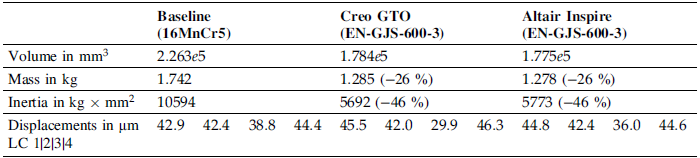
However, despite the different shapes, we summarized in Table 1 that both optimised designs met the prescribed displacement limit of less than 0.05 mm for all four load cases. At the same time, they achieved identical improvements in mass (−26 %) and moment of inertia (−46 %) compared with the baseline component, while its also to considered that the change in material attributes to 9 % weight savings, leading to 17 % weight savings due to the optimised geometry. These reductions confirm that mass minimisation served as an effective proxy objective for inertia reduction within the constraints of the available software environments.
Comparing the baseline with the optimisation results of Creo GTO and Altair Inspire

Both optimisation outcomes represent feasible designs within the defined manufacturing and structural constraints. The fact that two different GD tools produce distinct, yet equally valid, solutions broaden the design space available to engineers, offering additional design alternatives during early-phase product development.
Overall, the comparison demonstrates that commercially available GD tools can produce lightweight and manufacturable design proposals even when ideal objective functions, such as direct inertia minimisation, are not available. Their differing treatments of constraint handling and optimisation heuristics underline the importance of tool-specific parameter calibration. Furthermore, the results show that indirect approaches, including post-optimisation channel integration and mesh-based control of feature sizes, can be used to address manufacturing requirements effectively, thereby enabling industrially viable implementations of Design for Additive Casting.
The two optimization results show that GD tools offer fast workflows even if manual steps like PolyNURBS fitting or sequential manual integration of functional features like cooling channels is needed while resulting in better suited parts for the specific application.
4. Conclusion
This study investigated how commercial generative design tools can be utilised to address manufacturing-related constraints that are not directly implemented in the software. Using an industrial deflection lever to be optimised for Additive Casting as a representative use case, we evaluated to commercial available tools, PTC Creo GTO and Altair Inspire, how they handle manufacturing-relevant requirements such as wall-thickness control, integration of lubrication and cooling channels, and reductions in mass and inertia.
The results showed that both tools are capable of generating lightweight, structurally feasible design proposals that satisfy the prescribed displacement constraints. Although neither environment allows the moment of inertia to be defined as a direct optimisation objective, using mass minimisation as a surrogate led to identical reductions in mass (−26 %) and inertia (−46 %) compared with the baseline component. This demonstrates that indirect objective formulations can be effective in practice when direct objectives are unavailable.
Generalizing problems, a structured workflow and indirect objective formulation widen the application of current GD tools. Reducing barriers, opening the field of GD to a wide range of manufacturing processes state of the art tools are not yet developed for.
The investigation of functional features highlighted that the timing of feature integration is a key methodological decision. Integrating channels directly during optimisation embeds them consistently into the structure but restricts the design space and can compromise casting suitability. Adding channels and mounting points after optimisation in CAD geometry generation step preserves a broader solution space and supports manufacturing requirements more reliably. For practitioners, this trade-off suggests that post-optimisation feature integration is often preferable when manufacturability and flexibility are prioritised, whereas concurrent integration is more suitable when automation and tight coupling of features and structure are desired.
The proposed workflow was demonstrated for a complex, multifunctional, medium-volume cast components. For high-volume production many aspects can be transferred. GD is most impactful in early-stage development and redesign where topology most strongly influences mass and inertia.
Development of solid guidelines, different GD tools as well as different manufacturing processes like conventional sand casting is subject of future work. Taken together, the findings indicate that commercial generative design tools already provide strong support for DfAC, even when ideal objective functions and explicit constraints (e.g. maximum feature size, direct channel constraints) are not available. By combining tool-specific parameter calibration with indirect approaches, such as mesh-based control of feature sizes, manual geometry redesign, and post-optimisation feature integration, designers can obtain multiple, equally valid solutions that expand the available design space in early product development.
Acknowledgement
This research was funded by the Bavarian Research and Transformation Foundation within the Research Consortium FORAnGen under Grant Agreement number AZ 1625-24. The authors would like to express their sincere thanks to Otto Bihler Maschinenfabrik GmbH & Co. KG for providing the use case, granting permission to publish images and technical data, and for the fruitful discussions during the project.



 Open access

