

1. Introduction
Owing to their characteristic geometry, correct modelling of alpine-type glaciers usually requires three-dimensional (3-D) models in order to capture the specific features of their complex dynamics. However, for some glaciers, a relatively low aspect ratio (vertical to horizontal characteristic dimensions) allows the use of the shallow ice approximation (SIA) in two-dimensional (2-D) ice-flow models, provided the emphasis is on large-scale dynamic results as demonstrated by Reference Le Meur and VincentLe Meur and Vincent (2003) and Reference Le Meur, Gagliardini, Zwinger and RuokolainenLe Meur and others (2004). For instance, with such a 2-D SIA model, the dynamics of Glacier de Saint-Sorlin, France, have been modelled and successively compared to measurement data, making it possible to tune a number of key parameters (Reference Le Meur and VincentLe Meur and Vincent , 2003). Regarding the numerical scheme, this model was based on a finite-difference approach making use of the alternating-direction-implicit (ADI) method (Reference HutterHuybrechts, 1992).
A more recent appraisal of the model results, especially when conducted with synthetic, simple-shaped glaciers, showed that our implementation of this numerical scheme did not ensure correct mass conservation. This led us to propose a different numerical scheme (Reference Hindmarsh and PayneHindmarsh and Payne, 1996) that includes more implicitness than the ADI scheme and solves the mass conservation problem. Although mass conservation is important from a theoretical point of view, the real question is how much non-conservation will affect model behaviour, especially for real cases. Although the sensitivity to mass conservation differs greatly depending on the type of glacier modelled, it appears that in most cases the changes in dynamics between the two schemes remain limited. Note that checking for mass conservation with a real case such as Glacier de Saint-Sorlin is difficult to carry out. It was therefore decided to compare the two numerical schemes in terms of final steady-state surfaces. Despite minor differences in these surfaces, which tend to indicate that old results from the ADI scheme are still significant, it was decided to adopt the new scheme because of its relative ease of implementation and the limited extra computer resources it requires.
Whatever scheme is adopted, the way the ice flow is computed from one gridpoint to a neighbouring point sometimes leads to a physical inconsistency in the model, leading to negative ice thicknesses at some points. Simply setting these values to zero, as was initially done, is the simplest way of dealing with the problem but inevitably alters the total mass count. Some spurious dynamic effects could also be expected. A solution that incorporates systematic checks on the capability of peripheral points to provide ice to their neighbouring points partly solves this problem and also contributes to better mass conservation. Another inconsistency inherent in the old algorithm is the colonization of ice in the upper part of the glacier above the bergschrund, resulting in an overestimation of the local mass balance which also affects the ice dynamics. A solution in the form of a very simple additional check is proposed and offers a satisfactory remedy to the problem.
The paper is organized as follows: after identifying the mass conservation problem, the main equations of the SIA model are presented and used to introduce the new semiimplicit (SI) scheme (section 2). This is compared to the ADI scheme in section 3 for the simple case of a theoretical glacier (mass conservation) and for Glacier de Saint-Sorlin (mass conservation and steady-state geometries). Section 4 deals both with the problems of negative ice thicknesses and the upward extension of the glacier, and presents the proposed solutions. This helped in learning more about the dynamics of the glacier from the tracking of ice particles along their flow through the glacier.
2. ADI and SI Schemes
2.1. Main equations of the model within the shallow ice approximation
The main equation of the 2-D SIA model is derived from the continuity equation and gives the ice-thickness rate of change as a function of the local surface mass-balance value and the divergence of the flow:
where H is the ice thickness, q the horizontal ice flux and a the surface mass balance. Under the SIA (Reference Hindmarsh and PayneHutter, 1983) with a non-linear rheology for ice, namely the Glen’s flow power law with exponent n = 3 (Reference GlenGlen, 1955), Equation (1) can be written as the diffusion equation
where S is the surface elevation and D the diffusivity. The latter reads

with flow law rate factor A (1.3×10⁻²⁴Pa−3s−1 (m6 N−3s−1); see, e.g., Reference Vincent, Vallon and ReynaudVincent and others, 2000), ice density p (8.8 × 10²kgm−3) and gravitational acceleration g (9.81 ms−2). ∂H/∂t equals ∂S/∂t since ∂B/∂t = 0 (isostasy neglected). Sliding is accounted for in the form of a Weertman-type sliding law (Reference Le Meur and VincentWeertman, 1964) with a related sliding coefficient A s = 5.0 × 10⁻¹⁴ m8 N−3 a−1 (for more details see, e.g., Reference Le Meur and VincentLe Meur and Vincent , 2003). These equations are then approximated using finite differences.
2.2. Finite-difference discretization schemes
A SI scheme providing more implicitness is introduced as an alternative to the ADI scheme. A similar comparison of various schemes with different degrees of implicitness has been proposed by Reference Greve and CalovGreve and Calov (2002) and further details can be found in Reference HindmarshHindmarsh (2001).
For both the ADI and SI schemes, spatial discretization of the transport equation is carried out by computing the diffusion coefficients at ‘intermediate’ points on a staggered grid (Fig. 1) that are offset from the main points (where thickness and surface elevation are computed) by half a grid spacing (Δ/2). This spatial scheme is fully described in Reference Hindmarsh and PayneHindmarsh and Payne (1996, method 1). Although shifted in the x and y directions by Δ/2, indices for D are designated as integers for clarity such that Di j is computed from ice-thickness and elevation values at the four neighbouring points with indices (i, j), (i, j +1),(i +1, j) and (i + 1,j + 1).

Fig. 1. Staggered grid used for spatial discretization of the model. The area extent requires Nx by Ny gridpoints, but, for calculation purposes, indices are extended from 0 to Nx + 1 and Ny +1 for x and y directions respectively. Grid spacing Δ is the same in both directions.
Equation (2) is discretized by applying the finite-difference method after integration between t 0 and t 0 + Δt (for details see Appendix A). Depending on the chosen scheme (ADI or SI) certain surface terms are evaluated explicitly or implicitly in this discretized equation. The obtained matrix equations are then solved for the new surface elevation Si¦j at every gridpoint of the domain.
2.2.1. ADI scheme
With the ADI scheme, forward integration from t 0 to t 0+Δt is carried out in two half-steps (Δt/2) during which an implicit direction x or y is chosen. At each half-step, the central point and the two neighbouring points along the implicit direction are considered implicit, whereas remaining neighbouring surface points along the other direction are kept explicit. This leads to several tridiagonal matrices at each half-step (see Appendix B for details).
2.2.2. SI scheme
The SI scheme improves the degree of implicitness by considering all neighbouring points implicitly. This leads to one pentadiagonal matrix. Details of the terms of the SI matrix can be found in Appendix C. Inversion of this matrix is carried out using the LAPACK software package (Reference AndersonAnderson and others, 1999).
The main consequence in terms of CPU time is that the SI scheme allows a larger time-step. The more implicit a scheme, the larger the time-step it can adopt without becoming unstable. On the other hand, the new SI matrix is so much larger that its single inversion is more time-consuming than the previous ADI multiple inversions (see computational efficiency below).
2.2.3. Time-step
Several runs have been carried out in order to optimize the time-step in agreement with the grid spacing Δ = 50 m. For comparison of the two methods, a time-step of 0.05 years initially optimized for the ADI scheme will be used. Because of a higher degree of implicitness for the SI scheme, the associated optimal time-step can be increased up to 0.3 years. However, to avoid any spurious effect from too large a time-step, a value of 0.1 years will be used hereafter for simulations only requiring the SI method.
To compare the efficiency of the two schemes, a 100 year benchmark simulation with zero mass balance for a synthetic glacier (described in section 3.1) was run with time-steps of 0.05 and 0.3 years for the ADI and SI schemes, respectively.
With the ADI scheme, this simulation requires 19 s of CPU time, whereas 74 s are needed for the SI scheme. Even with fewer matrix inversions and a longer time-step compared to the ADI scheme, the SI scheme still needs more CPU time. Nevertheless, with grid sizes such as those used here, this increase of the order of a factor of 3–4 remains acceptable given the gain in accuracy expected.
3. Comparison of the Different Numerical Schemes in Terms of Mass Conservation
3.1. Mass non-conservation in the ADI case
The ADI scheme was identified as the cause of the mass conservation problem during simulations on a theoretical simply shaped glacier carried out to provide a better understanding of dynamic effects. The glacier was circularly symmetric with the shape of a flattened hemisphere and rested on an inclined plane with a uniform slope of 0.3, as can be seen in the inset of Figure 2. This simple geometry avoids dynamic effects driven by topographic irregularities and resulting complexities in the flow pattern. The experimental set-up consisted of an initially circular glacier of 700 m radius with a given maximal thickness of 140 m and a zero mass balance over the entire area. The model was run forward in time for 100 years with parameters similar to those used by Reference Le Meur and VincentLe Meur and Vincent (2003), that is a grid spacing of 50 m, a time-step of 0.05 years and with sliding incorporated. As can be seen from Figure 2 (curve labelled ADI), the total mass of the glacier is not constant and a gain in mass of about 5% can be detected after about 10 years of simulation. Despite a much less pronounced mismatch for the real case of Glacier de Saint-Sorlin (see section 3.3), this led us to question the ADI scheme or at least the way it is implemented in the model.

Fig. 2. Time-dependent total mass of the circularly symmetric synthetic glacier when modelled with the ADI and SI numerical schemes. The results have already been corrected for negative ice thicknesses as described in section 4.1. The inset shows the crosssection of the synthetic glacier resting on an inclined plane.
3.2. Mass conservation with the synthetic glacier in the SI case
The same experiment as in section 3.1 was performed with the new SI scheme, and the corresponding mass of the synthetic glacier during the 100 year simulation is depicted in Figure 2 (curve labelled SI). As can be seen from the figure, no mass change is detectable, which shows the efficiency of the new scheme with regard to mass conservation.
3.3. Evolution of Glacier de Saint-Sorlin
A similar comparison was then carried out for the more realistic case of Glacier de Saint-Sorlin. Again, the model was run forward in time for 100 years starting from the 1998 surface of the glacier (see, e.g., Reference Le Meur and VincentLe Meur and Vincent, 2003) and with a prescribed zero mass balance throughout, which made it possible to focus on the ability of the numerical scheme to conserve mass. As Figure 3 shows, the SI scheme strictly conserves mass similarly to the previous case, whereas a mass loss is observed with the ADI scheme. However, note that the Saint-Sorlin case is much less sensitive to mass nonconservation than the theoretical glacier. The mass loss after 100 years of simulation is less than 0.2%.

Fig. 3. Time-dependent total mass of Glacier de Saint-Sorlin for the two numerical schemes with zero mass balance. The same correction with regard to negative ice thicknesses as in Figure 2 has been applied.
The same experiment with a natural mass-balance field made it possible to assess more realistically the impact of the numerical scheme on the ice dynamics. The same comparison experiment (apart from the duration, which is now 300 years to ensure a steady state for the non-zero mass balan ce) was considered with both schemes, forced by the 1957–1997 measured average mass-balance field for the glacier (see section 4.2 and Fig. 4). Mass conservation is more difficult to assess here because the total ice mass count is modified by the prescribed surface mass balance and the fact that the glacier extent varies during the simulation. However, the SI scheme still proves more efficient (not shown). The focus is now on the comparison of final steady-state surfaces for both cases. As depicted in Figure 5, some changes can be detected, but they remain minor and are essentially concentrated at the glacier snout. Because of this limited sensitivity of Glacier de Saint-Sorlin to the numerical scheme with regard to mass conservation and ice dynamics, previous results such as those of Reference Le Meur and VincentLe Meur and Vincent (2003) can still be considered as significant for the overall glacier dynamics. However, as demonstrated above, some theoretical glacier configurations are definitely more sensitive, and we believe that switching to the SI method constitutes a real improvement in the correct representation of ice dynamics of several real-case glaciers.

Fig. 4. Average measured mass balance for Glacier de Saint-Sorlin for 1957–99 (adapted from Reference Le Meur and VincentLe Meur and Vincent, 2003).

Fig. 5. Steady-state simulation over 300 years for Glacier de Saint-Sorlin with the 1957–99 average measured mass balance. In (a) the ice thickness obtained with the SI numerical scheme is presented as well as the bedrock topography, whereas in (b) the absolute value of the difference (m) between the two schemes is shown.
3.4. Explanation for the mass-conservation properties of the ADI and SI schemes
With a zero surface mass balance, Equation (1) can be written
For mass to be conserved, spatial integration of the discretized flux divergence (∂qx/∂x + ∂qy/∂y ) should equal zero.
Integration of ∂qx/∂x in the x direction can be written such that all terms except those at the border of the grid cancel each other. The remaining border terms, which are proportional to the corresponding diffusion coefficients, finally reduce to zero since the domain is chosen such that its outer fringe remains ice-free, leading to zero diffusion coefficients there (for details see Appendix D1).
By contrast, spatial integration at the same half time-step of the term ∂qy/∂y in the y direction is not equal to zero (see Appendix D1) because of remaining terms of the form

The same calculation for the second half time-step leads to a similar result, which does not cancel out that of the first half time-step. Our implementation of the ADI scheme is therefore inherently non-mass conserving. It is possible to imagine another form of the ADI scheme (Appendix D2) that would be inherently mass conserving, but this alternative shows problems regarding numerical stability.
It can easily be shown that the SI scheme conserves mass, since ∂qx/∂x and ∂qy/∂y both have the same expression as ∂qx/∂x computed in the ADI scheme (by replacing t 0 + Δt/2 with t 0 + Δt), which equals zero after spatial integration.
A closer look at the remaining terms in Equation (4) shows that with the ADI scheme the non-conservation of mass should be more pronounced where the glacier undergoes the largest thickness changes. This was confirmed by running the model forward in time for 5 years with the SI scheme and the same glacier as above. From there, one more time-step was integrated with either the SI or the ADI scheme, and the differences in the final thicknesses were assessed.
Since the SI method conserves mass, points where there are differences with the ADI method are most likely those where errors on mass conservation originate. As can be seen in Figure 6, these areas correspond to those where the glacier surface evolved most over the last time-step, which confirms the link between mass non-conservation and the ice-thickness rate of change. It is therefore not surprising to observe that the glacier area near the snout is mainly conserved, since the initial glacier configuration is far from steady state (an extremely thin and extended glacier), leading the glacier to spread rapidly downstream. In this process of converging towards steady state, driving slopes and thicknesses rapidly reduce, thereby reducing the ice flow in such a way that the total mass eventually stabilizes (with the ADI scheme).

Fig. 6. Localization of the mass-balance error with the ADI scheme. The upper panel is a longitudinal profile showing both the difference between the two schemes (abs(ADI–SI), dashed curve) and the ice thickness change (abs(ΔH), dotted curve) during the last time-step with the SI method. From the inset in the lower panel, it is clear that this mass error (dark contours) is concentrated at the glacier area near the snout where the glacier undergoes the largest ice thickness changes.
The fact that Glacier de Saint-Sorlin is much less sensitive to the mass conservation problem (see section 3.3) now becomes clearer. The explanation probably resides in low dynamics for the glacier. Indeed, starting from the 1998 surface under a zero mass-balance field, forthcoming ice-thickness changes will only result from ice flow in a glacier with small driving slopes (at least compared to those of the beginning of the synthetic glacier).
Inspection of Equation (4) also suggests a possible effect of the time-step on the mass error term. This expression can in fact be summarized as D × ∂S/∂t × Δt. If the diffusion coefficient were time-step-independent, a time-step-independent total mass error could be expected, as the cumulative mass error should become something like D(S final − S initial). However, because D changes from one time-step to another, the error term grows with the chosen time-step, and in the particular case of the synthetic glacier we even observed strictly linear growth.
4. Further Improvements to the Model
4.1. Handling of negative ice thicknesses
Implementation of an ice-flow scheme requires careful attention as some gridpoints may undergo negative ice thicknesses, especially in the vicinity of the border of the glacier. In order to avoid the ensuing model crash, these negative ice thicknesses were first unsatisfactorily reset to zero, leading to a degradation in mass conservation and possible impacts on the ice flow. For instance, resetting the negative ice thicknesses to zero in a 100 year simulation of Glacier de Saint-Sorlin under zero mass balance led to an error of 20% on the final mass (when using the SI scheme).
When considering Equation (1) in its discrete form, given the new ice thickness at t 0 + Δt,
it is clear that negative ice thicknesses can be a consequence of a negative mass balance and/or of ice flow divergence exceeding the available amount of ice.
The problem of mass errors resulting purely from surface mass balance, especially with negative values downstream of the ice margin, has been treated by Reference Van den Berg, van de Wal and OerlemansVan den Berg and others (2006). In the present case, such negative ice thicknesses are simply set to zero. Methods to deal with negative ice thicknesses resulting from ice flow divergence are described in sections 4.1.1 and 4.1.2. Note that the results of Figures 3 and 5 have already been corrected using these methods.
4.1.1. Ice-free points at the border of the glacier
Because of the staggered grid and the way the diffusion coefficient is computed from neighbouring points, some ice can theoretically flow from an ice-free point towards one of its adjacent icy points, as shown in Figure 7a. In such a case, corresponding coefficients in the matrix are set such that outflow from this point as well as the relevant inflows towards the neighbouring points are zero. If such an ice-free point undergoes positive mass balance, the outflow remains zero as described above and the final thickness is set to this mass-balance value, which leads to a small error.

Fig. 7. The two conditions of negative ice thickness resulting from an erroneous ice-flow computation by the model.
The ice-free gridpoints seem to account for most of the mass error, given that the error in the run cited above (100 years, no mass balance, Glacier de Saint-Sorlin) is reduced from 20% to only 0.1%.
4.1.2. Lightly ice-covered points
This problem essentially concerns border points for which the theoretical ice outflow exceeds the available ice, as shown in Figure 7b. This is possible because this outflow depends on the four neighbouring diffusion coefficients, which are themselves computed from averaged neighbouring thicknesses and slopes. In fact, points where an excess of ice outflow can potentially occur are almost systematically border points with less than 10 cm of ice and at least one of the neighbouring points with more than 1 m of ice, leading to an overestimation of the diffusion coefficient. This error is therefore due to a geometrical problem, confirmed by the fact that varying the time-step brought no noticeable changes. We suspect a strong sensitivity to grid spacing instead.
In this case the ice thickness is only set to zero, as in the initial case. Mass conservation would require restricting the outflow to the available amount of ice. This is not easy as the outflow is split between the four neighbouring points. Note that this error remains small compared to the error in section 4.1.1.
4.2. Preventing spurious dynamics from ice above the bergschrund
4.2.1. Unrealistic ice settlement
The upper part of the glacier is outlined by a bergschrund above which no significant ice thickness can develop as slopes are too pronounced. Snow may temporarily accumulate there, but eventually avalanches or is blown away, ending up on the glacier downstream where it contributes to the mass balance. The mass-balance field depicted in Figure 4 already takes this extra snow into account as it is measured from stakes. Therefore, measurements should not be extrapolated to the region above the bergschrund, as this would be equivalent to counting the same snow twice in the glacier budget.
In other cases, for instance, if the mass-balance field comes from a mass-balance model (generally fed by climate model outputs), this snow redistribution must be accounted for explicitly. In any case, to prevent unrealistic ice development over the upper part of the glacier, ice is not allowed to settle over points satisfying the following three conditions: (1) the point lies in the region above the bergschrund, (2) it was initially not glaciated (for Saint-Sorlin the 1998 surface is taken as reference) and (3) the slope at that point is steeper than a certain threshold. Note that this test still allows the glacier to progress on flatter areas if allowed by the mass balance. This check was already used by Reference Le Meur and VincentLe Meur and Vincent (2003) but was not discussed explicitly.
4.2.2. Effects on modelled dynamics
The impacts on the glacier dynamics resulting from letting the ice settle, or preventing it from settling, above the bergschrund have been assessed by simulating the glacier starting from its 1998 surface under the 1957–99 average mass-balance field with and without applying this check.
The SI-simulated steady-state surface of the glacier as well as the time-dependent evolution of the total mass of the glacier when computed without this check is depicted in Figure 8. Observing the figure, the most striking result is the fact that, despite a negative specific mass balance of around −0.25 m w.e. a−1 (see Reference Le Meur and VincentLe Meur and Vincent, 2003 concerning a similar experiment), the glacier gains mass. Moreover, steady state is achieved only after 500 years of simulation time, which contradicts previous results with a similar experiment (Reference Le Meur and VincentLe Meur and Vincent , 2003).

Fig. 8. Steady-state ice-thickness distribution (a) and time-dependent total mass (b) for Glacier de Saint-Sorlin when ice is allowed to settle above the bergschrund.
The same experiment was performed with the ice prevented from colonizing areas above the bergschrund, and the corresponding results are depicted in Figure 9. The slope threshold was set to 0.7 corresponding to a slope of 35°. Results are quite different in terms of total ice mass evolution, since the glacier now loses mass, consistent with a negative specific mass balance, until achieving steady state. Furthermore, the time required to reach steady state and the final surface are now more compatible with results of Reference Le Meur and VincentLe Meur and Vincent (2003).

Fig. 9. As for Figure 8, but ice is prevented from settling above the bergschrund (with a slope threshold of 0.7).
The final surface also differs significantly. The difference between the two steady-state surfaces as depicted in Figure 10 is essentially concentrated over the glacier snout area and to a lesser degree over the area above the bergschrund. This suggests that over-thickening and over-expansion on the lower part of the glacier is a direct consequence of the unrealistic ice settlement above the bergschrund. To confirm this, the trajectories of particles deposited above the bergschrund are computed according to the previous steady-state surface of the glacier.

Fig. 10. Difference (m) between steady-state glacier surfaces with and without ice-settling restriction (absolute values).
Tracking of ice particles
Ice tracking consists of following ice particles during their travel inside the glacier from their sinking after deposition in the accumulation zone until their re-emergence at the surface in the ablation zone. Calculation of the trajectories is done iteratively; at each time-step, the three components of the steady-state velocity vector (u, v, w) are computed to obtain the new position of each particle at the next time-step (x n+1, yn+1 , z n+1 ). The relationship between the new and the previous position (xn, yn, zn ) is simply
The starting point x0, y0 can be chosen freely and z0 is then the surface elevation at this point. The iteration is stopped when the ice particle reaches the surface. Δt has been set at 0.05 years. Figure 11 shows the trajectories of selected particles deposited on the ‘forbidden settling zone’ (above the bergschrund). Also depicted are the two steady-state extents of the glacier when ice freely expands in the upper part (dotted curve) and when it is restricted according to our criterion (solid curve).
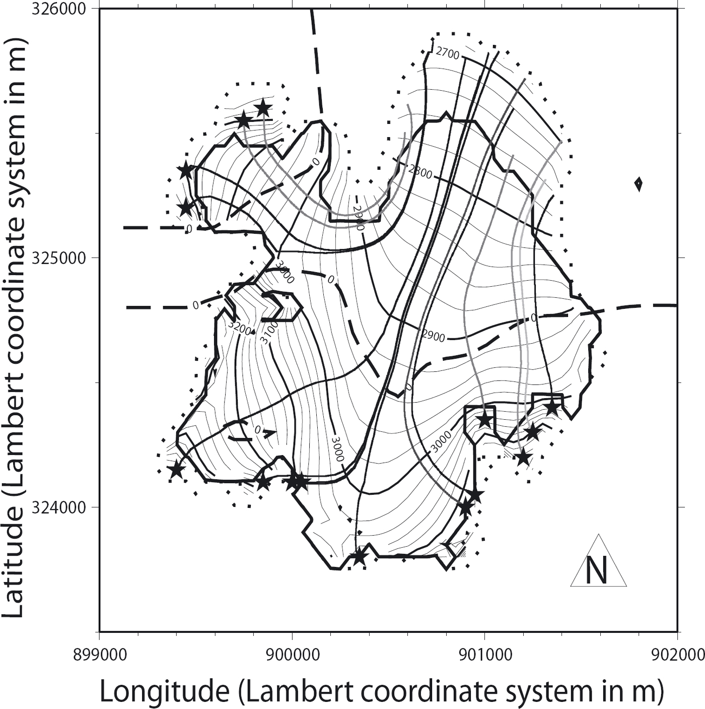
Fig. 11. Trajectories followed by ice particles deposited in the ‘forbidden zone’ (stars). The darker the featured trajectories, the longer the corresponding times between deposition and re-emergence. The two glacier extents with (full curve) and without (dotted curve) the ice-settling restriction are also shown as well as the equilibrium line (dashed curve indicating zero mass balance).
As expected, the figure confirms that particles deposited in the region above the bergschrund re-emerge in the overexpansion and over-thickening region in the lower part of the glacier.
This result is consistent with allowing ice to settle above the actual upper limit of the glacier when it has already been included in the mass balance further down the glacier, hence leading to an overestimation of the total glacier mass budget. This causes the glacier to grow whereas it should shrink under the 1957–99 average mass-balance field. The singularity in the time-dependent mass evolution shown in Figure 8 can now also be explained. Under a negative specific balance of −0.25 m w.e. a−1, the glacier starts shrinking but later grows to an erroneous steady-state configuration due to the spurious ice settling over the bergschrund.
5. Conclusions
Several shortcomings of a 2-D SIA ice-flow model applied to an alpine glacier have been identified and corresponding solutions proposed. First, the initial ADI numerical scheme used so far proved deficient with regard to mass conservation, although the consequences on the actual dynamics of Glacier de Saint-Sorlin remain limited. Because some other types of glaciers might be more sensitive to mass conservation, an SI scheme is proposed as an alternative due to its ability to conserve mass and for its low costs (easy implementation and limited CPU time).
Two other problems concerning the flow of ice and the way it is accounted for in the model appear to alter the total mass count with potential effects on ice dynamics. The first illustrates the inability of the model to distribute ice in a consistent manner between certain points, mainly on the glacier periphery. Appropriate methods are proposed that solve most of the errors. Lastly, with the help of particle tracking, a tendency of the modelled glacier to extend above its upper bergschrund has been identified as the main cause of an overestimation of the glacier mass balance with noticeable changes on the glacier behaviour. A very simple solution to this problem based on the slope of the bedrock is described and demonstrates the importance of understanding the real physics of glaciers rather than solely relying on model equations.
Acknowledgements
We thank all those who contributed to the data collection effort on Glacier de Saint-Sorlin. Support from the French Ministry of Research financing the GLACIOCLIM Observatory (http://www-lgge.ujf-grenoble.fr/ServiceObs/) and from INSU (Institut National des Sciences de l’Univers du CNRS) is gratefully acknowledged. This work benefited from financial support from the French glacier survey observatory, part of the Observatoire des Sciences de l’Univers de Grenoble (OSUG). We express our gratitude to R. Greve, R.C.A. Hind-marsh and F. Saito for considerably improving the quality of this paper.
Appendix A. Discretization of the Ice-Thickness Equation
Discretization of the ice-thickness Equation (2) requires the calculation of several derivatives according to

Therefore,

and


The diffusivity D splits into a deformation component Ddef and a sliding component Dslid according to

and their discretizations lead to


Finally, the discretized version of the ice-thickness Equation (2) can be written

where k = (ρg3/5) x (Δt /Δ2).
In the last equation, the lower indices for the surface S refer to the gridpoints. Depending on the position indices, S on the lefthand side is evaluated either at t1, t2 or t3. Respective values for these times depend upon the selected scheme and reflect its degree of implicitness, as detailed in Appendices B and C. The terms on the righthand side and the diffusitivity D are always evaluated explicitly, that is, at time t o .
Appendix B. ADI Scheme
Forward integration of Equation (2) is carried out in two half-steps during which an implicit direction is chosen. For instance, during the first half-step, the system is solved according to the lines x, y where the x, y directions are denoted by the indices i, j. This implies that the system variables can be reduced to the central point (i, j) and the two neighbouring points alongthe implicitdirection with indexes (i − 1, j)and (i +1, j). Therefore, upper surface points ![]()
![]() are considered implicit (evaluated at to
+ Δt/2), whereas remaining neighbouring surface points along the y direction
are considered implicit (evaluated at to
+ Δt/2), whereas remaining neighbouring surface points along the y direction ![]() remain explicit (i.e. evaluated at t
0).That means t
1 = t
2 = to
+ Δt/2 and t
3 = to
.
remain explicit (i.e. evaluated at t
0).That means t
1 = t
2 = to
+ Δt/2 and t
3 = to
.
For each of the lines (terms of constant index j), this leads to a system of Ny equations with three unknowns (Ny being the number of rows) written in a matrix form implying a tridiagonal matrix. After inverting all of the Nx resulting matrices (Nx being the number of lines), an intermediate surface at t 0 + Δt/2 is obtained, and from this surface, the second step of the forward integration is now performed according to the rows (y direction) in order to provide the final surface at to + Δt. This procedure is exactly the same as above but with inversion of indices i and j. It then leads to t 1 = t 3 = t 0 +Δt , t 2 = t 0 +Δt/2.
Appendix C. SI Scheme
In this scheme, all neighbouring points are considered implicitly, that is, directly at t0 + Δt, leading to t 1 = t 2 = t 3 = t 0 + Δt. The area needs to be swept only once, leading to a system that can now be expressed with a pentadiagonal NxNy x NxNy matrix resulting from NxNy equations with five unknowns (central and all neighbouring points evaluated at to + Δt),
where ![]() is the vector of all implicit surface elevations
is the vector of all implicit surface elevations ![]() A is a pentadiagonal matrix and
A is a pentadiagonal matrix and ![]() is a vector of all explicit terms, including the previous step surface and mass balance at all NxNy
gridpoints (i, j) of the domain.
is a vector of all explicit terms, including the previous step surface and mass balance at all NxNy
gridpoints (i, j) of the domain.
Reshuffling Equation (A10) gives the entries of the A matrix of Equation (C1). A is a Nx Ny x Nx Ny matrix, indexed by ind = (j − 1) Nx + i.
With c 1 = 0.5 x Δt/Δ2, the entries of the five diagonals of A can be written
The remaining terms are equal to zero. The values of the vector ![]() are given by
are given by
Appendix D. Mass Conservation
D1. ADI case
Once integrated over the first half time-step with the ADI scheme, the x and y derivatives of the flux along the x and y directions can be expressed as

and

where c = 2(ρg)3/5. Spatial integration of ∂qx/∂x gives the following equations for all values of j:


and finally goes to zero since the domain is chosen such that its outer fringe remains ice-free, leading to zero diffusion coefficients at points (0, j), (0, j – 1), (Nx, j) and (Nx, j – 1).
Spatial integration at the same half time-step of the term ∂qy/∂y in the y direction gives

for all i. Because of remaining terms of the form

spatial integration of ∂qy/∂y (and therefore that of ∂qx/∂x+ ∂qy/∂y) over the first half-step is not equal to zero.

D2. An alternative form of the ADI scheme
In order to guarantee ![]() as well as Δ ·
as well as Δ ·
![]() at each half time-step, another form of the ADI scheme can be proposed. So far, all Si,j terms (first line of Equation (A10)) have been considered to be implicit for both half time-steps, whereas Si,j
[1 + k(Di,j
+ Di,j-1
+ Di—1j +D
i–1/
·
j–1
) could be considered implicit and Si,j
[k(D
i,j
+ Di,j_1
+ Di–1j + Di–1
,
j–1
)] left explicit. Over the first half time-step, this leads to the same expression for ∂qx/∂x as before, whereas the expression for ∂qy∂y then reads
at each half time-step, another form of the ADI scheme can be proposed. So far, all Si,j terms (first line of Equation (A10)) have been considered to be implicit for both half time-steps, whereas Si,j
[1 + k(Di,j
+ Di,j-1
+ Di—1j +D
i–1/
·
j–1
) could be considered implicit and Si,j
[k(D
i,j
+ Di,j_1
+ Di–1j + Di–1
,
j–1
)] left explicit. Over the first half time-step, this leads to the same expression for ∂qx/∂x as before, whereas the expression for ∂qy∂y then reads
It can easily be shown that this leads to ![]() (similar to the approach used with Equation (D2)). An analogous calculation leads to the same result for the second half time-step.
(similar to the approach used with Equation (D2)). An analogous calculation leads to the same result for the second half time-step.
Although it is inherently mass-conserving, under certain geometrical conditions this scheme is numerically unstable unless abnormally small time-steps are used. In a sensitivity test, we observed that some reasonable geometries (bedrock and ice surface slopes) require very small time-steps of the order of 0.001 years. This means that in order to avoid any numerical instability for the various geometries possibly encountered with a real glacier, the time-step has to be extremely small. It was therefore impossible for us to use an ADI scheme that was both inherently mass-conserving and numerically stable.


