


1. INTRODUCTION
As a consequence of a strong seasonality in the climate of the subtropical semiarid Andes (29°–34°S), the mass balance of glaciers in this region is characterized by a well-defined winter accumulation season (April–September) and a warm and dry ablation season, when clear-sky conditions dominate (Pellicciotti and others, Reference Pellicciotti2008; Rabatel and others, Reference Rabatel, Castebrunet, Favier, Nicholson and Kinnard2011; Masiokas and others, Reference Masiokas2016). During the austral winter, snow accumulates in the Andes Cordillera when cold precipitation fronts arrive from the Pacific Ocean, accounting for 85–95% of annual precipitation (Masiokas and others, Reference Masiokas, Villalba, Luckman, Le Quesne and Aravena2006; Falvey and Garreaud, Reference Falvey and Garreaud2007; Viale and others, Reference Viale, Nuñez and Nuñez2011). The frequency and magnitude of the precipitation fronts determine the amount of snow deposited over Andean glaciers (Masiokas and others, Reference Masiokas, Villalba, Luckman, Le Quesne and Aravena2006, Reference Masiokas2012), but the final spatial distribution of the accumulated snow mass is also shaped by other processes typical of mountainous catchments, such as orographic effects, preferential deposition, avalanching and wind redistribution (Gascoin and others, Reference Gascoin, Lhermitte, Kinnard, Bortels and Liston2013). During summer, the ice and seasonal snowpack melt due to stable, warm and dry conditions maintained by the strengthening of the South Pacific Anticyclone (Montecinos and Aceituno, Reference Montecinos and Aceituno2003; Valdés-Pineda and others, Reference Valdés-Pineda, Valdés, Diaz and Pizarro-Tapia2015). The spatial patterns of snow and ice melt over glaciers are determined by the energy exchanges between the glacier surface and its surrounding atmosphere. A significant aspect of the subtropical semiarid Andes climate is that the combination of high-elevation and a warm and dry atmosphere might produce larger sublimation than on other glaciers located in more humid environments. It has been suggested that sublimation could represent a significant portion of total ablation and eventually reduce the contribution to runoff from glaciers and the seasonal snowpack (Favier and others, Reference Favier, Falvey, Rabatel, Praderio and Lopez2009; Gascoin and others, Reference Gascoin2011; MacDonell and others, Reference MacDonell, Kinnard, Mölg, Nicholson and Abermann2013). However, most of the estimates have been made at the point-scale and there are no studies focusing on the spatial and temporal distribution of ablation rates over the entire extent of a glacier in this region.
During summer, the contrast between a cold glacier surface and a warm surrounding atmosphere produces a stable atmospheric condition in which katabatic winds typically form. These winds consist of cold air masses moving down-slope due to density differences with the surrounding warm atmosphere. Previous studies have shown that katabatic winds can modify the spatial distribution of near-surface air temperature and wind speed and, consequently, the energy exchanges between the glacier surface and the atmosphere (van den Broeke, Reference van den Broeke1997a; Denby and Greuell, Reference Denby and Greuell2000; Oerlemans and Grisogono, Reference Oerlemans and Grisogono2002). In particular, it has been shown that during the occurrence of katabatic winds, near-surface air temperatures cannot be described by a linear altitudinal gradient (Greuell and Böhm, Reference Greuell and Böhm1998; Shea and Moore, Reference Shea and Moore2010; Petersen and others, Reference Petersen, Pellicciotti, Juszak, Carenzo and Brock2013; Ayala and others, Reference Ayala, Pellicciotti and Shea2015). The interaction of katabatic winds with mesoscale systems and other processes occurring within the atmospheric boundary layer, such as slope or valley winds, further complicates the modelling of the meteorological variables that affect the glacier energy balance (van den Broeke, Reference van den Broeke1997b; Oerlemans, Reference Oerlemans, Holtslag and Duynkerke1998). Typically, the calculation of meteorological variables over mountain glaciers has been carried out using on-glacier measurements and simple extrapolation approaches, such as uniform distributions or linear lapse rates. An alternative has been the derivation of on-glacier conditions from synoptic or mesoscale atmospheric forcing, using statistical relations (e.g. Schneeberger and others, Reference Schneeberger, Albrecht, Blatter, Wild and Hock2001; Radić and Hock, Reference Radić and Hock2006) or dynamical atmospheric modelling (e.g. Mölg and Kaser, Reference Mölg and Kaser2011; Collier and others, Reference Collier2013; Collier and Immerzeel, Reference Collier and Immerzeel2015).
Previous studies have derived estimates of melt and surface sublimation rates for glaciers of the semiarid Andes using point-scale observations (Ginot and others, Reference Ginot, Kull, Schotterer, Schwikowski and Gäggeler2006; Gascoin and others, Reference Gascoin2011), point-scale energy-balance models (Corripio, Reference Corripio2003a; Pellicciotti and others, Reference Pellicciotti2008; MacDonell and others, Reference MacDonell, Kinnard, Mölg, Nicholson and Abermann2013) and regional atmospheric circulation models (Favier and others, Reference Favier, Falvey, Rabatel, Praderio and Lopez2009). Other studies have calculated only melt by including a temperature-index model in glacier mass-balance reconstructions (Masiokas and others, Reference Masiokas2016), and catchment-scale hydrological models (Ragettli and Pellicciotti, Reference Ragettli and Pellicciotti2012; Ayala and others, Reference Ayala2016). Estimates of surface sublimation rates are between 1 and 6 mm w.e. d−1 and represent up to 81% of total ablation at glacierized sites above 5000 m a.s.l (MacDonell and others, Reference MacDonell, Kinnard, Mölg, Nicholson and Abermann2013). To date, the most detailed physically-based distributed modelling study of glaciers in the semiarid Andes is the one by Gascoin and others (Reference Gascoin, Lhermitte, Kinnard, Bortels and Liston2013) over the partly glacierized Pascua-Lama catchment (29°S) using SnowModel, which calculates surface and blowing snow sublimation (Liston and Elder, Reference Liston and Elder2006a). However, they focused on the accumulation season and the effect of wind on the snow dynamics in that period. More recently, a large-scale study used the same model to simulate snow dynamics and glacier mass balance along the entire Andes Cordillera at a spatial and temporal resolutions of 1 km and 3 h, respectively (Mernild and others, Reference Mernild, Liston, Hiemstra and Wilson2017).
In this study, we calculate the spatial distribution of energy fluxes and ablation rates over the surface of an Andean glacier during the austral summer at a high spatial resolution (50 m), which allows the inclusion of small-scale processes, such as katabatic and valley winds, refreezing and topographic shading, and knowledge of the local variability of topographic parameters, such as sky-view factors and local slopes. Our main objectives are to: (i) advance our understanding of glacier ablation in the subtropical semiarid Andes by providing the first spatially-distributed quantification of energy fluxes and ablation rates on a glacier in this region and (ii) explore the use in energy-balance models of two methods to generate fields of near-surface air temperature and wind speed, which provide new alternatives to solve some of the interactions between large-scale meteorological forcing and the atmospheric boundary layer over a mountain glacier during the summer period. These methods are the ModGB model (Ayala and others, Reference Ayala, Pellicciotti and Shea2015), which reproduces a characteristic spatial pattern of near-surface air temperature observed over mountain glaciers during warm ambient conditions, and the methodology presented by Peleg and others (Reference Peleg, Fatichi, Paschalis, Molnar and Burlando2017), which simulates fields of wind speed over rough terrain as a function of the free atmospheric flow, the atmospheric stability conditions and topographic parameters.
2. STUDY SITE AND DATA
2.1. Juncal Norte Glacier
We selected Juncal Norte Glacier as our study site. This glacier lies in the semiarid Andes of central Chile in the Aconcagua River catchment, next to the Chilean-Argentinean border (Fig. 1a and Table 1). The glacier provides a key contribution to runoff during the austral summer (Ohlanders and others, Reference Ohlanders, Rodriguez and McPhee2013; Ragettli and others, Reference Ragettli, Immerzeel and Pellicciotti2016; Rodriguez and others, Reference Rodriguez, Ohlanders, Pellicciotti, Williams and Mcphee2016) and its hydrological significance is likely to increase during periods of drought, such as the one experienced by central Chile during the period 2010–15 (Boisier and others, Reference Boisier, Rondanelli, Garreaud and Muñoz2016; Cornwell and others, Reference Cornwell, Molotch and McPhee2016; Garreaud and others, Reference Garreaud2017).
(a) The location of Juncal Norte Glacier in the semiarid Andes of central Chile, with the Aconcagua River catchment indicated. (b) Map of Juncal Norte Glacier, with the location of the AWSs and the colour code showing the calculated flowline. (c) Tongue of Juncal Norte Glacier. We use the same numbering of AWSs as in Pellicciotti and others (Reference Pellicciotti2008) in a similar field campaign on Juncal Norte Glacier during summer 2005/06.

Main characteristics of Juncal Norte Glacier

The glacier has a north-facing aspect and is one of the largest glaciers in central Chile with an area of 7.6 km2 and an elevation range of almost 3000 m (2904–5896). The glacier flows northwards from an upper cirque that extends down to ~4500 m a.s.l. and its tongue extends along a 5 km valley of ~1 km wide. The presence of thin debris patches is noticeable at its terminus and lateral sites. While other glaciers in the study region have lost almost 63% of their area in the period 1955–2013, Juncal Norte Glacier had one of the slowest recession rates (14 m a−1) and it only lost 10% in the same period (Janke and others, Reference Janke, Bellisario and Ferrando2015; Malmros and others, Reference Malmros, Mernild, Wilson, Yde and Fensholt2016). Pellicciotti and others (Reference Pellicciotti2008) measured total ablation rates of ~3.7 m w.e. during the summer season 2005/06 at the glacier tongue. At a glacier-wide scale, Ragettli and Pellicciotti (Reference Ragettli and Pellicciotti2012) and Ragettli and others (Reference Ragettli, Cortés, Mcphee and Pellicciotti2014) estimated average melt rates of 20 mm w.e. d−1 using the TOPKAPI-ETH hydrological model. Surface sublimation at one location on the glacier tongue was calculated with a point-scale energy-balance model to be 38 mm w.e. by Pellicciotti and others (Reference Pellicciotti2008) during the summer season 2005/06.
2.2. Field measurements
A field campaign to measure meteorological, hydrological and glaciological data at Juncal Norte Glacier was carried out from December 2008 to February 2009 in the context of the ACQWA project from the European Union (http://www.acqwa.ch/). As the access to the upper areas of the glacier is difficult, field measurements were concentrated on the glacier tongue at elevations between 3000 and 3400 m a.s.l., within a horizontal distance of 2 km (Figs 1b, c). The dataset acquired during this field campaign has been previously used for hydrological modelling (Ragettli and Pellicciotti, Reference Ragettli and Pellicciotti2012; Ragettli and others, Reference Ragettli, Cortés, Mcphee and Pellicciotti2014) and the modelling of near-surface air temperature (Petersen and Pellicciotti, Reference Petersen and Pellicciotti2011; Ayala and others, Reference Ayala, Pellicciotti and Shea2015). This field campaign was a follow-up to a similar study that took place in summer 2005/06 (Pellicciotti and others, Reference Pellicciotti2008).
Meteorological measurements were conducted at three Automatic Weather Stations (AWSs) that recorded incoming and reflected shortwave radiation, wind speed and direction, air temperature and relative humidity (Figs 1b, c and Table 2). One of the AWSs was placed in the proglacial valley and the other two on the glacier tongue (Figs 1b, c). As the on-glacier AWSs sat on tripods, they sank with the melting surface and thus maintained a distance of 2 m to the surface during the entire study period. As it was installed over a snow surface that later revealed the presence of an irregular ice surface, AWS3 was more affected by levelling issues than AWS1. In addition, a set of 12 low-cost temperature sensors (T-loggers) was installed on the glacier tongue to record the spatial distribution of air temperature. The T-loggers consisted of a Hobo H8 Pro Temp sensor (Onset Computer Corporation, 2003) with an internal data logger inside a PVC cylinder that was fixed at 2 m on a vertical pole. The poles sat on a tripod and maintained a constant height during the study period. Air temperature was measured every 5 min. The temperature sensors were naturally ventilated by the channelized wind flow inside the PVC cylinders and the cylinders were shielded from direct solar radiation using aluminium foil (Petersen and Pellicciotti, Reference Petersen and Pellicciotti2011). In this study, we use the pre-processed dataset from Petersen and Pellicciotti (Reference Petersen and Pellicciotti2011), who corrected for outliers and errors in the T-loggers data. As in Ayala and others (Reference Ayala, Pellicciotti and Shea2015), we neglect three T-loggers that show several gaps in their records and use a subset of nine T-loggers that shared the longest common period of measurements (indicated in Fig. 1c). All data are aggregated to hourly averages. The location of AWSs and T-loggers is shown in Figures 1b, c and Table 2 lists technical details of the sensors.
Main characteristics of the AWSs

T a, air temperature; RH, relative humidity; WS, wind speed; S in , shortwave radiation; SH, surface height.
A set of 16 ablation stakes was installed on the glacier tongue on 8 December 2008 and readings were performed regularly during the study period (Figs 1b, c). The ablation stakes span 2.2 km of horizontal distance and 270 m of elevation. A snow pit was dug next to AWS3 on 7 December 2008, when a snow density of 481 kg m−3 was measured. An Ultrasonic Depth gauge (UDG Campbell SR50) was installed on an arm fixed to a pole drilled into the ice next to AWS1 and measured 5 min records of surface height.
We complement the data from the field campaign with hourly temperature records from Portillo AWS (32.8412°S, 70.0942°W, 3000 m a.s.l.), located ~20 km to the north of Juncal Norte Glacier and operated by the Chilean Water Authority (Dirección General de Aguas, DGA). Data from this station are used to represent local off-glacier conditions, as AWS2 in the proglacial valley has been shown to be affected by glacier winds (Pellicciotti and others, Reference Pellicciotti2008).
Air temperature (Fig. 2a), specific humidity (Fig. 2b), wind speed (Fig. 2c) and wind direction (Fig. 2d) exhibit a strong diurnal variability. Diurnal values of air temperature on the glacier tongue (AWS1 and AWS3) vary between 4 (at 7–8 am) and 12°C (at 4 pm). The proglacial station (AWS2) has higher temperatures and a larger range of diurnal variation (between 6 and 18°C) than the on-glacier AWSs. The smaller air temperature range at the on-glacier stations is related to the cooling influence of the glacier surface, which dampens diurnal fluctuations. Average diurnal cycles of specific humidity vary between 2.8 and 5.5 g kg−1. The observed increase in air temperature during the afternoon is associated with a strong decrease of humidity at all stations.
Summary of meteorological observations during the study period. (a–d) Average diurnal cycles of air temperature, specific humidity, wind speed and wind direction, (e–g) Frequency of wind direction at the three AWSs, with the colour code showing the corresponding velocities (wind roses), (h) On-glacier air temperature observations as a function of elevation and fitted lapse rates (LR). In panel (h) warm (red), average (yellow) and cold (blue) off-glacier conditions are determined using the data within the percentiles 0–10, 45–55 and 90–100 of Portillo air temperature (see Section 5.1).

Constant katabatic winds dominate at all AWSs between 7 and 12 pm (Figs 2c–g). Afternoon hours are characterized by an increase in wind speed associated with the appearance of up-valley winds carrying dry warm air masses from the lower elevations of Juncal River catchment (Petersen and Pellicciotti, Reference Petersen and Pellicciotti2011). These winds can be clearly seen in the change of wind direction at the proglacial station (Figs 2d, f) and are consistent with observations in 2005/06 (Pellicciotti and others, Reference Pellicciotti2008). Changes in wind speed are also notable at AWS1 and AWS3, but the change in wind direction is not as evident as at AWS2 (Figs 2d, e, g). At all sites, however, the change in wind direction of the afternoon hours corresponds to the wind maxima.
Figure 2h shows air temperature recorded at the T-loggers as a function of elevation. Similarly to Ayala and others (Reference Ayala, Pellicciotti and Shea2015), we define three categories of observations as a function of off-glacier temperatures (from Portillo AWS) that represent cold (blue), average (yellow) and warm (red) ambient conditions. The three categories contain on-glacier temperatures recorded at time steps between percentiles 0–10, 45–55 and 90–100 of Portillo AWS air temperature. The objective is to show changes in air temperature lapse rates as a function of external meteorological conditions. Figure 2h shows how the lapse rate on Juncal Norte Glacier increases its magnitude from −4.4 °C km−1 during cold periods to −12 °C km−1 during high temperature episodes. Importantly, for high off-glacier temperatures, the correlation coefficient between air temperature and elevation increases from 0.64 to 0.96 (Petersen and Pellicciotti, Reference Petersen and Pellicciotti2011; Ayala and others, Reference Ayala, Pellicciotti and Shea2015).
2.3. DEM, reanalysis data and initial conditions
The topography of Juncal Norte Glacier was extracted from a 30 m resolution DEM produced by the Aster GDEM v2 project (Tachikawa and others, 2011). To reduce computational costs, the DEM was resized to a 50 m resolution using a bilinear interpolation.
We obtain the dominant synoptic meteorological conditions at the time of the field campaign from the ERA-Interim reanalysis (Dee and others, Reference Dee2011). From this dataset we extract specific humidity, air pressure and wind speed at different pressure levels at a spatial resolution of 0.125° and a temporal resolution of 6 h, which was linearly interpolated to hourly time steps. These data are used in the generation of forcing fields of wind speed (Section 3.1.2) and humidity (Section 3.1.3).
As initial condition to the energy-balance simulations, we use distributed maps of surface albedo and snow water equivalent (SWE) from a hydrological simulation of Juncal Norte Glacier that included the accumulation season (Ragettli and others, Reference Ragettli, Cortés, Mcphee and Pellicciotti2014). As these maps were produced by the TOPKAPI-ETH glacio-hydrological model at a resolution of 100 m, we perform a linear interpolation to the 50 m resolution of the DEM used in this study.
3. METHODS
3.1. Generation of input meteorological fields
3.1.1. Air temperature
We generate fields of near-surface air temperature using a combination of linear lapse rates, under cold ambient conditions (below 0°C), and the ModGB air temperature model suggested by Ayala and others (Reference Ayala, Pellicciotti and Shea2015), under warm ambient conditions (above 0°C). The latter attempts to reproduce the effects on near-surface air temperature of the interaction between katabatic winds and external sources of heat over glacier tongues. ModGB is a modified version of the thermodynamic model proposed by Greuell and Böhm (Reference Greuell and Böhm1998) (GB), which solves the energy balance of an idealized air parcel that comes in to contact with a cold glacier surface in the upper section of the glacier and descends along the flow line due to its density difference with the surrounding warm atmosphere. As the air parcel descends, it cools down by turbulent exchange of sensible heat with the cold glacier surface, but it heats up due to adiabatic warming. Theoretically, at a sufficient long distance, these two processes reach an equilibrium and the temperature of the air parcel converges to a constant value. In practice, katabatic winds are usually mixed on the glacier tongue with up-valley and slope winds, producing a warming effect and steep temperature gradients well correlated with elevation on the lowest glacier section (Petersen and Pellicciotti, Reference Petersen and Pellicciotti2011). These effects on near-surface air temperature were shown to exist for high ambient temperatures and the ModGB model to be superior than linear lapse rates for those conditions (Ayala and others, Reference Ayala, Pellicciotti and Shea2015).
The ModGB model calculates fields of near-surface air temperature on melting glaciers as a function of the distance along the flow line, using the equations derived in Ayala and others (Reference Ayala, Pellicciotti and Shea2015):
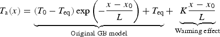 $$T_{\rm a}(x) = \underbrace{{(T_0 - T_{{\rm eq}})\exp \left( { - \displaystyle{{x - x_0} \over L}} \right) + T_{{\rm eq}}}}_{{{\rm Original\; GB\; model}}} + \underbrace{{K\displaystyle{{x - x_0} \over L}}}_{{{\rm Warming\; effect}}}$$
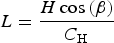 $$L = \displaystyle{{H\cos {\rm (}\beta {\rm )}} \over {C_{\rm H}}}$$
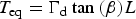 $$T_{{\rm eq}} = {\rm \Gamma} _{\rm d}\tan \,(\beta )L$$
where T a is near-surface air temperature [°C], x is the distance along the flow line [m], T 0 is air temperature at the theoretical location (x 0) where the air enters the katabatic layer [°C], T eq is the equilibrium temperature reached, in the original GB model, at x = ∞ [°C], L is a characteristic length scale [m], K is an empirical factor that represents the additional heat sources over the glacier tongue [°C], H is the height of the katabatic boundary layer [m], β is the average glacier slope [°], C H is the bulk transfer coefficient (assumed equal to 0.002 as in the original GB model) and Γd is the dry adiabatic lapse rate (−0.0098 °C m−1).
We apply the ModGB model at sites below the elevation of x 0 (a point referred to as z 0) only at time steps when the air temperature at x 0 is high enough to generate katabatic winds, typically some degrees above 0°C (Shea and Moore, Reference Shea and Moore2010; Ayala and others, Reference Ayala, Pellicciotti and Shea2015). In all other conditions, when temperature shows a strong correlation with elevation over the entire glacier length, we use linear lapse rates, as well as for sites above x 0.
Similarly to Ayala and others (Reference Ayala, Pellicciotti and Shea2015) and Petersen and others (Reference Petersen, Pellicciotti, Juszak, Carenzo and Brock2013), we use H and K as tuning parameters. We obtain the location of z 0 (and the equivalent x 0) and the variation of H and K as a function of off-glacier temperatures using the following approach: (i) we calculate air temperature at a set of z 0 (and equivalent x 0) values within the glacier elevation range using the Environmental Lapse Rate (ELR = −0.0065 °C m−1) and off-glacier temperature data from Portillo AWS, (ii) we calculate air temperature over the glacier tongue using the ModGB model and the possible locations for x 0, (iii) we select the best location of x 0 and preliminary values for H and K by minimizing the Root Mean Squared Error (RMSE) between the ModGB simulated values and the T-loggers observations, (iv) once x 0 is selected, we split the calculated values of air temperature at x 0 (T 0) in bins of 1°C, (v) we calibrate a new value of H and K for each T 0 temperature bin (also minimizing the RMSE) and (vi) we fit a curve to the relations found between H, K and T 0, which are later used to apply the model.
3.1.2. Wind speed
Turbulent heat fluxes are highly sensitive to variations in local wind speed and this sensitivity increases with higher air temperatures (Dadic and others, Reference Dadic2012). Modelling of wind is, however, challenging and the assumption of a uniform wind speed across a glacier is frequently used in energy-balance studies (Hock and Holmgren, Reference Hock and Holmgren2005; Anslow and others, Reference Anslow, Hostetler, Bidlake and Clark2008; Gabbi and others, Reference Gabbi, Carenzo, Pellicciotti, Bauder and Funk2014). This assumption is certainly unrealistic on large glaciers and reduces the spatial variability of energy and mass balance.
To simulate wind speed, we derive vertical wind profiles along the glacier elevation using the similarity-theory model proposed by Zilitinkevich and others (Reference Zilitinkevich, Johansson, Mironov and Baklanov1998), as used by Burlando and others (Reference Burlando, Carassale, Georgieva, Ratto and Solari2007) and Peleg and others (Reference Peleg, Fatichi, Paschalis, Molnar and Burlando2017). In this method, horizontal components of wind speed of free atmospheric flow (above the local topography) are rotated and projected over the vertical axis using logarithmic vertical profiles that are derived depending on the current atmospheric stability conditions, providing near-surface wind fields. The necessary inputs to the model are the speed and direction of the free atmospheric flow, the incoming shortwave radiation (measured at from AWS1) to derive atmospheric stability and the aerodynamic surface roughness length of the glacier surface (see Section 4.2). As representative of free atmospheric flow at that site, we use horizontal wind components at 450 HPa (at ~6600 m a.s.l.) from the ERA-Interim reanalysis dataset. The obtained near-surface fields of wind speed are further modified for the effect of elevation, slope and curvature using the equations included in the MicroMet model (Liston and Sturm, Reference Liston and Sturm1998; Liston and Elder, Reference Liston and Elder2006b), which has been used in previous snow simulations on glaciers of the semiarid Andes (Gascoin and others, Reference Gascoin, Lhermitte, Kinnard, Bortels and Liston2013; Mernild and others, Reference Mernild, Liston, Hiemstra and Wilson2017). This modification increases wind speed at high-elevation and wind-exposed sites compared with valley bottoms and wind-protected slopes.
Peleg and others (Reference Peleg, Fatichi, Paschalis, Molnar and Burlando2017) included this approach in a distributed weather generator model to generate near-surface wind speed on a 625 km2 domain in the complex orography of the Swiss Alps. Their study concluded that the model correctly reproduces several statistics of the wind speed and direction ground data, but extreme events are not well simulated. This is the first time that this method is used to generate distributed near-surface wind fields over a mountain glacier.
3.1.3. Incoming radiation and specific humidity
We distribute three components of the shortwave radiation: direct, diffuse and reflected from the surrounding terrain. Direct shortwave radiation measured at AWS1 is distributed over the glacier as a function of the position of the sun and the slope and aspect of each grid cell. Diffuse (reflected) shortwave radiation measured at AWS1 is distributed as a function of the sky (sun-exposed terrain) view factor. The fraction of shortwave radiation measured at AWS1 that corresponds to diffuse and direct radiation is theoretically calculated based on the average latitude of the catchment, day of the year, hour of the day and atmospheric transmissivity coefficients using the equations detailed in Corripio (Reference Corripio2003a), Pellicciotti and others (Reference Pellicciotti, Raschle, Huerlimann, Carenzo and Burlando2011) and Carenzo (Reference Carenzo2012). We assume that 5% of the observed radiation at AWS1 corresponds to reflected radiation from the surrounding terrain.
Incoming longwave radiation is calculated at each grid cell of the model domain as the sum of the longwave radiation from the sky, the snow-covered terrain and the snow-free terrain, following Corripio (Reference Corripio2003a) and Carenzo (Reference Carenzo2012):
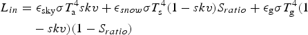 $$\eqalign{L_{in} & = \epsilon _{{\rm sky}}\sigma T_{\rm a}^{\rm 4} skv + \epsilon _{snow}\sigma T_{\rm s}^{\rm 4} (1 - skv)S_{ratio} + \epsilon _{\rm g}\sigma T_{\rm g}^{\rm 4} (1 \cr & \quad - skv)(1 - S_{ratio})}$$
where L in is total incoming longwave radiation [Wm−2], ε sky is the emissivity of the sky [-], σ is the Stefan-Boltzmann constant [-], skv is the sky view factor [-], ε snow is the emissivity of a snow surface [-], T s is the surface temperature at the grid cell [K], S ratio is the ratio between the area of snow-covered cells to the glacier catchment area [-], ε g is the emissivity of the bare ground [-] and T g is the temperature of the surrounding ground that we assume equal to the air temperature at each grid cell [K]. As clear sky conditions dominate at Juncal Norte Glacier (Corripio, Reference Corripio2003a; Pellicciotti and others, Reference Pellicciotti2008), we use the Prata (Reference Prata1996) parametrization for clear sky longwave emission to estimate ε sky . The Prata (Reference Prata1996) parametrization depends on precipitable water and it has been previously used in point-scale energy-balance models in the semiarid Andes of central Chile (Corripio, Reference Corripio2003a; Pellicciotti and others, Reference Pellicciotti2008).
Specific humidity from the different pressure levels in the ERA-Interim reanalysis is linearly interpolated to every grid cell based on its elevation. As the reanalysis data are not representative of the conditions within the glacier boundary layer, we modify their values using a linear correction. At each time step, we calculate a correction factor equal to the ratio between the specific humidity at AWS1 (calculated from the observed air temperature and relative humidity) and that interpolated to the corresponding AWS1 grid cell. The correction factor is then used at each time step to correct the ERA-Interim interpolated values across the entire glacier domain.
3.2. Distributed energy-balance model
We use the generated meteorological fields to force a two-layer distributed energy-balance model. Following previous studies on this glacier, we set a depth of d 1 = 5 and d 2 = 25 cm for the top and second layers, respectively (Pellicciotti and others, Reference Pellicciotti2008, Reference Pellicciotti, Ragettli, Carenzo and McPhee2014). We assume that all forcing energy fluxes are absorbed in the first centimetres, i.e. in the top model layer. This assumption is well justified for longwave radiation and turbulent heat fluxes, but it is arguable for shortwave radiation, which might penetrate several centimetres in the ice depending on the radiation wavelength and the impurities in the ice (Bintanja and van den Broeke, Reference Bintanja and van den Broeke1995; Mölg and others, Reference Mölg, CUllen, Hardy, Kaser and Klok2008; Oerlemans, Reference Oerlemans2010). However, as shortwave radiation is not able to penetrate snow, which typically covers the glacier accumulation area, and the ice of Juncal Norte Glacier tongue is likely to have some impurities from the surrounding debris that enhance absorption, we decided to neglect the penetration of shortwave radiation into depths larger than 5 cm. Consequently, at every grid cell the energy-balance equation of the top (or surface) layer is:
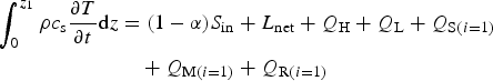 $$\eqalign{\int_0^{z_1} {\rho c_{\rm s}} \displaystyle{{\partial T} \over {\partial t}}{\rm d}z & = (1 - \alpha )S_{{\rm in}} + L_{{\rm net}} + Q_{\rm H} + Q_{\rm L} + Q_{{\rm S}(i = 1)} \cr & \quad + Q_{{\rm M}(i = 1)} + Q_{{\rm R}(i = 1)}}$$
where ρ is the snow or ice density [kg m−3], c s is the specific heat capacity [J kg−1 K−1], T is the snow or ice temperature [K], z is the vertical axis (positive downward) [m], α is the surface albedo [-], S in is the incoming shortwave radiation, L net is the net longwave radiation, Q H is the sensible heat flux and Q L is the latent heat flux. Q S(i=1), Q M(i=1) and Q R(i=1) are the conductive heat flux, the latent heat from melt and the latent heat from refreezing in the top layer, respectively. Index i refers to the layer number and all energy fluxes are in W m−2. As no precipitation was observed during the study period, snow mass accumulation and heat from the rain were neglected. The equation of the second layer only includes the subsurface heat fluxes, latent heat from melt and latent heat from refreezing:
 $$\int_{z_1}^{z_2} {\rho c_{\rm s}} \displaystyle{{\partial T} \over {\partial t}}{\rm d}z = Q_{{\rm S(}i = 2{\rm )}} + Q_{{\rm M(}i = 2{\rm )}} + Q_{{\rm R(}i = 2{\rm )}}$$
Conductive heat fluxes are calculated by solving the heat equation for two layers, similar to Klok and Oerlemans (Reference Klok and Oerlemans2002), as:
 $$Q_{{\rm S(}i = 1{\rm )}} = k_{\rm T}\displaystyle{{(T_2 - T_{\rm s})} \over {d_1}}$$
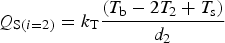 $$Q_{{\rm S(}i = 2{\rm )}} = k_{\rm T}\displaystyle{{(T_{\rm b} - 2T_2 + T_{\rm s})} \over {d_2}}$$
where k T is thermal conductivity [W m−1 K−1], T 2 is the temperature of the second layer [K] and T b is a boundary condition that corresponds to the temperature of the glacier below the second layer [K]. Thermal conductivity is calculated as a function of density in the case of snow (Sturm and others, Reference Sturm, Holmgren, König and Morris1997) and assumed as 2.07 W m−1 K−1 in the case of ice (Pellicciotti and others, Reference Pellicciotti, Carenzo, Helbing, Rimkus and Burlando2009). We estimate T b as the weekly running mean of air temperature at each grid cell (Carenzo, Reference Carenzo2012).
If the temperature of a layer reaches 0°C in Eqns (5) and (6), the latent heat from melt is calculated as the residual of the energy-balance equation. Total melt (M) is calculated as:
 $$M = \displaystyle{{\mathop \sum \nolimits_i Q_{Mi}} \over {\lambda _{\rm f}\rho _{\rm w}}}$$
where Q Mi is the latent heat of fusion due to melt at layer i [W m−2], λ f is the latent heat of fusion (3.34·105 J kg−1) and ρ w is the density of water.
In the presence of snow, we assign to each layer a maximum storage capacity of liquid water, which is a function of snow density (Anderson, Reference Anderson1976; Essery and others, Reference Essery, Morin, Lejeune and Ménard2013). The top layer transfers its excess meltwater to the second layer, but if both layers are saturated all excess meltwater is converted to runoff. Refreezing of meltwater occurs in snow layers when the layer temperature drops below 0°C and the liquid content is more than zero. Snow density, as measured in the snow pit at the beginning of the study period, is kept constant during the entire simulation. Variations in albedo are parametrized as a function of the cumulative daily maximum positive temperature since snowfall at each grid cell (Brock and others, Reference Brock, Willis and Sharp2000). At the starting point of the simulation, we calculate the value of cumulative daily maximum positive temperature using the initial albedo map and solving the Brock and others (Reference Brock, Willis and Sharp2000) parameterization.
The model calculates surface temperature T s from Eqn (5) and outgoing longwave radiation using the Stefan–Boltzmann equation:
 $$L_{{\rm out}} = \epsilon _{\rm s}\sigma T_{\rm s}^{\rm 4} $$
where L out is outgoing longwave radiation [W m−2], ε s is surface emissivity (taken equal to 1) (Reid and others, Reference Reid, Carenzo, Pellicciotti and Brock2012; Juszak and Pellicciotti, Reference Juszak and Pellicciotti2013; MacDonell and others, Reference MacDonell, Kinnard, Mölg, Nicholson and Abermann2013), σ is the Stefan–Boltzmann constant [W m−2 K−4] and T s is surface temperature [K].
Turbulent heat fluxes are calculated using a first order closure of the turbulence, a stability correction based on the similarity theory of Monin and Obukhov (Reference Monin and Obukhov1954) and the parameterization of surface roughness length for temperature and humidity proposed by Andreas (Reference Andreas1987). The turbulent fluxes are calculated as:
 $$\eqalign{Q_{\rm H} & = \; \rho _{{\rm air}} \cdot c_{\rm p} \cdot k^2 \cdot WS \cr & \quad \cdot \displaystyle{{T_{\rm a} - T_{\rm s}} \over {({\rm ln((}z_{{\rm ins}} - d_0)/z_{\rm m}{\rm )} - {\rm \Psi} _{\rm m}) \cdot ({\rm ln((}z_{{\rm ins}} - d_0)/z_{\rm t}{\rm )} - {\rm \Psi} _{\rm t})}}}$$
 $$\eqalign{Q_{\rm L} & = \; \rho _{{\rm air}} \cdot \lambda _{\rm v} \cdot k^2 \cdot WS \cr & \quad \cdot \displaystyle{{q_{\rm a} - q_{\rm S}} \over {({\rm ln((}z_{{\rm ins}} - d_0)/z_{\rm m}{\rm )} - {\rm \Psi} _{\rm m}) \cdot ({\rm ln((}z_{{\rm ins}} - d_0)/z_{\rm q}{\rm )} - {\rm \Psi} _{\rm q})}}}$$
where ρ air is air density (1.26 kg m−3), c p is the specific heat of air [J kg−1 K−1], K is the Von Karman constant (0.4), WS is wind speed [m s−1], λ v is the latent heat of vaporization/sublimation [J kg−1], q a and q s are the specific humidity of air and glacier surface [-], z ins is the instrumental height [m], d 0 is the displacement length [m] calculated as in Brutsaert (Reference Brutsaert1982), z m, z t and z q are the aerodynamic surface roughness length for momentum, temperature and humidity [m] and Ψm, Ψt and Ψq are the vertically integrated stability correction functions [-]. A complete description of the chosen equations to model turbulent fluxes can be found in Carenzo (Reference Carenzo2012) and Dadic and others (Reference Dadic2012). We use an aerodynamic surface roughness length for momentum of 1 and 2 mm for snow and ice, respectively (Pellicciotti and others, Reference Pellicciotti2005). Latent heat fluxes are converted to a water loss or gain based on their direction, i.e. towards or away from the surface. During time steps at which surface temperature is below 0°C only sublimation and deposition can occur, but if the surface temperature reaches 0°C, evaporation and condensation can also occur. As the differentiation between evaporation and sublimation (and condensation and deposition) when the air temperature reaches 0°C is difficult, we assume that negative (positive) latent heat fluxes correspond only to sublimation (deposition), i.e. no evaporation (condensation) is calculated.
3.3. Sensitivity analyses and comparison with simple methods of meteorological variables distribution
Air temperature plays a crucial role in the calculation of incoming longwave radiation and turbulent heat fluxes. Indeed, air temperature lapse rates have been recognized as one of the variables to which glacier melt is most sensitive (MacDougall and others, Reference MacDougall, Wheler and Flowers2011; Ragettli and Pellicciotti, Reference Ragettli and Pellicciotti2012; Ayala and others, Reference Ayala2016), but the sensitivity of distributed estimates of surface sublimation has not been analysed. As we test a new approach to derive forcing fields of air temperature on distributed energy-balance models, we perform a sensitivity analysis of melt and surface sublimation to variations in air temperature.
We select for the analysis the off-glacier lapse rate, because it directly controls air temperature on the upper glacier areas and indirectly on the glacier tongue, through the ModGB model. The objective of this analysis is to calculate the variations of melt and surface sublimation produced by changes in the mesoscale patterns of air temperature, represented, in this case, by the off-glacier lapse rate. First, we define a reference model run in which we use an off-glacier temperature lapse rate equal to the ELR (see Section 3.1.1). Four additional simulations are run using values of 80, 90, 110 and 120% of the ELR, which produces air temperature lapse rates between −5.2 and −7.8 °C km−1. A large number of air temperature lapse rates reported on alpine regions during summer are within this range of variation (Rolland, Reference Rolland2003; Pigeon and Jiskoot, Reference Pigeon and Jiskoot2008). We note, however, that these average lapse rates are sometimes affected by temperature inversions, which are not considered in our model.
Finally, to further assess the impact of using our proposed methods, we compare our results to those derived from the use of simple and commonly used strategies to distribute air temperature and wind speed. In the case of air temperature we use a uniform and constant linear gradient (extrapolated from AWS1) equal to the ELR, and in the case of wind speed we use a uniform value equal to that measured at AWS1 at each time step. We run three new simulations of the energy-balance model using different combinations of our approaches and these simple assumptions: (i) linear gradient and uniform wind speed (ELR-uWS), (ii) linear gradient and distributed wind speed (ELR-dWS), and (iii) ModGB model and uniform wind speed (ModGB-uWS).
4. RESULTS
4.1. Input meteorological fields
Results from the ModGB parameter calibration (explained in Section 3.1.1) yield values of 4000 m a.s.l. and 4500 m for z 0 and x 0, respectively. The variation of H and K as a function of T 0 is presented in Figure 3, where a power function is fitted to the discrete values of H and K for every 1°C interval. When T 0 is below 5°C, H and K converge to very large values outside the ranges obtained for higher temperatures, and we thus decided to only use the ModGB model when T 0 ≥ 5°C. The convergence of H and K to these large values occurs when the ModGB equation is fitted to air temperature data that follows a linear gradient. This threshold for the use of the ModGB model is consistent with the threshold for the onset of katabatic winds found on other glaciers (Shea and Moore, Reference Shea and Moore2010; Ayala and others, Reference Ayala, Pellicciotti and Shea2015). In this way, we apply the ModGB model to calculate air temperature at sites below z 0 during time steps when T 0 ≥ 5°C. The ELR, applied at the data from Portillo AWS, is used for sites above z 0 when T 0 ≥ 5°C and for the entire glacier, starting from AWS1, when T 0 <5°C.
Calibrated values of ModGB parameters H and K as a function of the air temperature at the theoretical location where the air enters the katabatic layer (T 0). A power function is fit to each set of points. R 2 are 0.7621 for H and 0.7646 for K.

In Figure 4 we show the average distributed air temperature for cold and warm off-glacier conditions, defined as a function of percentiles of Portillo air temperature (as explained in Section 5.1). While cold conditions (Fig. 4a) corresponds to linear gradients (because T 0 <5°C), warm conditions (Fig. 4b) reflect the application of ModGB at elevations below z 0. The ModGB model reproduces the steep temperature gradients observed at the glacier terminus, but the total effect is the homogenization of temperatures along the entire glacier tongue. This effect can also be better seen in Figures 4c, d, where simulated and observed air temperatures are plotted against elevation and the flow line, at elevations below z 0. In Figure 4d, the curve corresponding to the P90–100 percentiles shows a stable or slowly increasing air temperature at flow line distances between 5000 and 7000 m. This effect is caused by the turbulent heat flux exchanged with the glacier surface (the ‘original GB model term’ in Eqn (1)). At flow line distances larger than 7000 m, air temperatures increase due to other heat sources (the ‘warming effect’ term in Eqn (1)).
(a) Map of average air temperature during the 10% coldest time steps at Portillo AWS, (b) Map of average air temperature during the 10% warmest time steps at Portillo AWS, (c and d) Averages of simulated (colour points) and observed (black circles) air temperatures versus elevation (c) and distance along the flow line (d) during the 10% coldest (in blue) and 10% warmest (in red) time steps at Portillo AWS.

Figure 5 summarizes results from the wind field modelling. While the glacier centre flow line presents uniform wind speeds (~4 m s−1) along the entire elevation range, the lateral slopes at the upper sections of the glacier are more exposed to large-scale winds and wind speed can reach values of up to 8 m s−1 (Fig. 5a). This effect is confirmed by Figure 5b, where higher magnitude and spatial variability of wind speed is evident at higher elevations. Similarly, Figure 5c shows a decrease in magnitude and spatial variability of wind speed at the glacier terminus. The aspect of each grid cell does not seem to play a significant role for its average wind speed over the study period, as similar ranges of wind speed can be found for each geographical orientation (Fig. 5d). This is likely related to changes in the dominant wind direction of the free atmospheric flow, as simulated by the ERA reanalysis. As the glacier has a north-facing aspect, the boxplot corresponding to orientation south is built with few data points. With some exceptions, Figure 5e shows that sites with steep slopes, likely at high elevations, tend to be windier than flat sites, mostly located along the central flow line.
(a) Map of average wind speed, (b–e) Distribution of wind speed as a function of topographic parameters, the central mark of each boxplot is the median, the box shows the 25th and 75th percentiles and the whiskers extend to the most extreme data points, (f and g) Frequency distributions of observed wind speed at the on-glacier AWSs and simulated wind speed at the corresponding grid cells.

In Figures 5f, g, we compare observations of wind speed at AWS1 and AWS3 with simulated values at the corresponding grid cells. Not surprisingly, simulated wind speeds capture neither the frequency distribution nor the diurnal variation (not shown) of observed values. Indeed, as shown in Section 5.1 and as described by Petersen and Pellicciotti (Reference Petersen and Pellicciotti2011), wind speeds at the glacier tongue are mostly driven by local wind systems, i.e. katabatic and valley winds, whereas simulated wind speeds are calculated using the dominant large-scale conditions. Nevertheless, we note that the order of magnitude of observed wind speeds is correctly approximated and it is likely that large-scale conditions play a more significant role at higher elevations. Strengths and weaknesses of using the proposed method to distributed wind speed and the implications for the energy fluxes are discussed later in Section 5.
Figure 6a shows a map of average incoming shortwave and longwave radiation. Due to its north-facing aspect and the dominant clear sky conditions, Juncal Norte Glacier receives large amounts of incoming shortwave radiation, ranging from 190 to 335 W m−2 as the average rate over the entire simulation period. The central glacier flow line receives the largest daily input of shortwave radiation (>300 W m−2 as average rate), whereas the lateral slopes receives smaller values. This effect is produced by the west and east orientation of the lateral slopes, which prevent them from receiving morning and afternoon sun rays, respectively. In comparison with shortwave radiation, incoming longwave radiation shows lower maximum values (265 W m−2) and a stronger connection to elevation differences, due to the temperature dependence. Figures 6c, d present a comparison between observed and simulated diurnal cycles of incoming shortwave radiation at the on-glacier AWSs. The model performance shows good values of commonly used fit indices with a RMSE of 7.45 and 90.85 W m−2 and a mean bias of −2.23 and 7.91 W m−2 for AWS1 (which was used as reference to distribute shortwave radiation) and AWS3, respectively. The relatively large RMSE observed at AWS3 can be explained by differences between the slope of the 50 m grid cell and the local slope, a possible tilt of the radiation sensor as the snow melted and differences between the episodic cloud cover at AWS 1 and 3.
(a, b) Maps of average incoming shortwave and longwave radiation, (c, d) Comparison of average diurnal cycles of observed incoming shortwave radiation at the on-glacier AWSs and simulated values at the corresponding grid cells.

4.2. Energy and summer mass balance
We validate the results of the energy-balance model using the set of ablation stakes readings and the UDG at AWS1 (Fig. 7). Results are good and show that the model correctly reproduces ablation patterns on the glacier tongue with a slight tendency to underestimation at stakes 1, 2, 5, 6, 7, 8, 10, 12 and 14. The average bias and RMSE of the simulations of surface lowering are −23.5 and 39.3 mm. Errors are not associated with a particular elevation band or glacier region and are most likely related to differences between one point and the 50 m grid cells.
Comparison of observed and simulated cumulative ablation at the location of the two AWSs and ablation stakes. The blue line shows readings at the UDG at AWS1 and violet diamonds are the surface height readings at all sites. Simulated values are extracted from the DEM for the corresponding grid cells. Values of mean bias and root mean squared error (RMSE) between the simulations and the ablation stakes are provided. The average bias and RMSE are −23.5 and 39.3 mm. The elevation of each stake is also indicated.

Average results of the distributed energy fluxes and total mass-balance components are presented in Figure 8. Both energy fluxes and mass-balance components present a large spatial variability with distinct patterns. Net shortwave radiation is the largest component of the energy balance and its values range from 70 W m−2 at the snow-covered upper areas to 285 W m−2 on the low-albedo ice-exposed glacier tongue (Fig. 8a). The longwave radiation balance results in an energy loss ranging from −75 to −45 W m−2 (Fig. 8b). Maximum longwave radiation losses are located in the accumulation area in correspondence to areas with the highest solar irradiance (Fig. 6a). Sensible heat fluxes are positive and reach up to 65 W m−2 at the glacier terminus, where air temperature is highest, but are close to zero at the wind-protected upper sites of the glacier cirque (Fig. 8c). Latent heat fluxes are negative across the entire glacier and vary from −70 to −10 W m−2 (Fig. 8d). The largest negative values are found at the wind-exposed lateral sites. At the lower sites, net longwave radiation and turbulent heat fluxes nearly balance each other out, with net shortwave radiation providing most of the energy for melt. In the upper areas, the net radiation balance and the sensible heat fluxes are close to zero, with negative latent heat fluxes controlling surface sublimation. In fact, while melt amounts are large at elevations below 3500 m a.s.l. (4300 mm w.e.) and decrease to zero above 5500 m a.s.l. (Fig. 8e), surface sublimation increases with elevation from 30 to 130 mm w.e.. Refreezing varies from 0 to 610 mm w.e. with a maximum between 4500 and 5000 m a.s.l.. Since the model only considers refreezing within the snowpack, this maximum is explained by two reasons: (i) at lower elevations the snowpack depth is small and it is quickly depleted as the summer advances and (ii) at higher elevations melt amounts are small and thus liquid water available for refreezing is almost absent. Above 4500 m a.s.l., melt dominates the wind-protected strong-radiated central areas and sublimation is largest at the lateral wind-exposed sites. Averaged over the entire glacier, surface sublimation and melt sum to 82.8 mm w.e. (6.5% of total ablation) and 1194.1 mm w.e., respectively.
Maps of average energy fluxes and total mass balance components over the 2-month study period.

Figure 9 presents altitudinal profiles of total ablation, melt, surface sublimation and refreezing, which are used to investigate the elevation dependence of the energy and mass fluxes. Here we refer to total ablation as the sum of melt and surface sublimation. Ablation rates, averaged over the study period and within each elevation band, decrease from 70 mm w.e. d−1 at 3000 m a.s.l. to <5 mm w.e. d−1 above 5500 m a.s.l. (Fig. 9a). The variability of ablation rates within the same elevation (black lines in Fig. 9) is relatively large between 3500 and 5500 m a.s.l., likely due to the large range of aspect and slope at those elevations, which is not observed on the glacier tongue or at the highest sites. Melt slowly decreases as percentage of the total ablation from nearly 100% at the glacier terminus to 80% ~5250 m a.s.l. Above this level, the percentage of melt over total ablation decreases fast, reaching 50% ~5600 m a.s.l. and 20% at the highest sites of the glacier (5896 m a.s.l.). Surface sublimation follows the opposite behaviour. Refreezing increases from 0 to 75% ~5200 m a.s.l. Above this elevation, almost all available meltwater refreezes. Figures 9b, c show the same profiles as in Figure 9a for two 10-days periods during December and January. Ablation rates at the glacier terminus are higher in December than in January, but over the entire glacier total ablation increases from 207.7 mm w.e. in December to 230.8 mm w.e. in January. In December (Fig. 9b), melt is less dominant in the mass balance than in January and the transition from melt to sublimation as the dominant ablation component occurs at a lower elevation (Fig. 9c). In January, melt represents more than 50% of total ablation up to 5700 m a.s.l. and almost 40% of total ablation at the highest glacier sites. As the season advances and the snowpack at high-elevation sites melts, refreezing becomes more important at those sites where meltwater appears.
Mass-balance components calculated by the distributed energy-balance model as a function of elevation. The lines are drawn based on spatial averages over 100 m elevation bands. The left axis shows the percentage that melt, sublimation and refreezing represent of the total ablation, which is shown in absolute values on the right axis. Black lines around ablation values represent maximum and minimum values at that elevation.

Figure 10 shows the variation of diurnal cycles of average energy fluxes (for the reference model run) and ablation rates (for the reference model run and the sensitivity experiments) for three elevation bands. Net shortwave radiation is the dominant component of the energy balance, but its magnitude decreases with elevation mostly as a result of the higher albedo. In fact, despite its connection to air temperature, the altitudinal variation of net longwave radiation is considerably smaller than that of net shortwave radiation. Positive sensible heat fluxes decrease with elevation to almost zero at 5500 m a.s.l. and negative latent heat fluxes are large during daytime and tend to increase in magnitude with elevation, because of the increase of wind speed and water vapour pressure gradient associated with temperature differences between the air and the glacier surface. Surface sublimation rates increase with elevation from 1.0 mm w.e. d−1 at 3500 m a.s.l. to 1.5 mm w.e. d−1 at 5500 m a.s.l. and show a strong diurnal cycle with values close to zero during night and large values in the afternoon. This diurnal variation tends to be enhanced at higher elevation. On the other hand, melt rates vary from 49.5 mm w.e. d−1 at 3500 m a.s.l. to 2.3 mm w.e. d−1 at 5500 m a.s.l. Melt exhibits peak values during the time of maximum shortwave radiation and values close to zero at night time. At 5500 m a.s.l., melt occurs only during 4–5 h in the afternoon (Fig. 10f).
Average diurnal cycles of energy fluxes (for the reference model run) and ablation rates (for the reference model run and the sensitivity experiments) for three elevation bands (a and b: 3500 ± 10, c and d: 4500 ± 10 and e and f: 5500 ± 10 m a.s.l.). Ablation rates on the second y-axis indicate either sublimation (left panels, a, c and e) or melt (right panels, b, d and f) and are calculated for the reference model run and for sensitivity analysis runs using 80% (−0.0052 °C m−1) and 120% (−0.0078 °C m−1) of the air temperature ELR. Daily average sublimation and melt rates are shown in the upper left corner of each panel. S net is the net shortwave radiation, L net is the net longwave radiation, Q H is the sensible heat flux and Q L is the latent heat flux.

4.3. Sensitivity analysis and comparison to simple methods of meteorological variables distribution
The central columns of Table 3 present the variation of glacier-wide melt and sublimation rates as a function of the off-glacier lapse rate. In the reference model run, daily average rates of glacier-wide melt and surface sublimation are 19.9 and 1.4 mm w.e. d−1, respectively. These rates proportionally decrease as we use steeper values for the off-glacier lapse rate. The use of steeper lapse rates to extrapolate air temperature from Portillo AWS decreases air temperatures at the glacier upper sites, which effectively diminishes energy inputs from longwave radiation and sensible heat fluxes (reducing melt) and increases relative humidity (reducing surface sublimation). We calculate average changes of −0.19 mm w.e. d−1%−1 for melt and −0.01 mm w.e. d−1%−1 for surface sublimation, given a change in the ELR. We note that, as depicted in Figure 10, the sensitivity of ablation rates to air temperature lapse rates is not the same over the entire glacier. In fact, most of the variations on ablation rates are concentrated in the upper sites (Figs 10e, f). The use of a lapse rate equal to 0.8*ELR drives the glacier surface at 5500 m a.s.l. to reach the melting temperature more often than using a steeper lapse rate, producing considerably larger melt rates (Fig. 10f).
Sensitivity of glacier-wide melt and sublimation rates to variations in off-glacier lapse rates and results of the additional simulations using simple assumptions to distribute air temperature and wind speed

ELR, environmental lapse rate; uWS, uniform wind speed; dWS, spatially distributed wind speed.
In Table 3 (right columns), the comparison between our reference results and those from simple assumptions show that the use of a uniform and constant temperature gradient from AWS1 (simulation ELR-dWS) reduces melt and surface sublimation in 20.0 and 14.3%, respectively. These differences are likely caused by a lower air temperature, linked to the use of an on-glacier AWS as base station, in opposite to the ModGB model, which uses the off-glacier Portillo AWS. Additionally, the ModGB model produces over the glacier tongue high air temperatures, which are linked to the steep gradients observed during the afternoon. On the other hand, the use of a uniform wind speed field (simulation ModGB-uWS) produces an increase of 5.0% in melt and a decrease of 21.4% of surface sublimation, which can be both explained by the decrease in magnitude of negative latent heat fluxes at high-elevation, wind-exposed sites. The combined effect of using both simple strategies (simulation ELR-uWS) produces a decrease of 17.6 and 28.6% of melt and surface sublimation, respectively.
Figure 11 shows the spatially distributed differences between the ELR-uWS simulation and the reference one. Melt derived from the proposed methods is higher than that obtained in the ELR-uWS simulation over the lowest glacier sections and the upper cirque, but the spatial patterns look similar because the main control of melt is shortwave radiation (Figs 11a–c). On the contrary, surface sublimation shows different spatial patterns on both simulations, suggesting that the topographic exposure to large-scale winds shapes its spatial distribution (Figs 11d–f). Importantly, the spatially uniform wind fields decrease the coefficient of variation (CV) of surface sublimation (from 0.53 to 0.43), which is characterized by large spatial variations (Gascoin and others, Reference Gascoin, Lhermitte, Kinnard, Bortels and Liston2013; Groot Zwaaftink and others, Reference Groot Zwaaftink, Mott and Lehning2013; Musselman and others, Reference Musselman, Pomeroy, Essery and Leroux2015; Sauter and Galos, Reference Sauter and Galos2016). We also find that the ELR-uWS simulation has a lower performance in the reproduction of the ablation stakes readings than the reference simulation. The ELR-uWS underestimates the observed ablation in 15.9 mm more than what the reference simulation does, resulting in an increase of 12.8% in the RMSE averaged over the entire set of ablation stakes (with a maximum of 40.7%), in comparison with that shown in the caption of Figure 7.
Maps of total melt and surface sublimation from the reference simulation (a and d), the linear lapse rate and uniform wind speed (ELR-uWS) simulation (b and e) and their differences (reference minus ELR-uWS, c and f). The spatial coefficient of variation is given at panels a, b, d and e.

5. DISCUSSION
5.1. Meteorological modelling
As previously described, the generation of meteorological fields is a crucial step in glacier energy-balance calculations (MacDougall and Flowers, Reference MacDougall and Flowers2011; Pellicciotti and others, Reference Pellicciotti, Ragettli, Carenzo and McPhee2014) for which strong assumptions, such as uniform wind speed or glacier-wide linear lapse rates, are often applied. In comparison with those simple approaches, our methods are able to reveal some of the spatial and temporal patterns that would be otherwise neglected. In the context of glacier mass-balance models, our strategy to distribute meteorological variables over the surface of a mountain glacier can be considered of intermediate complexity between simple extrapolation methods (e.g. Klok and Oerlemans, Reference Klok and Oerlemans2002; MacDougall and Flowers, Reference MacDougall and Flowers2011; Huintjes and others, Reference Huintjes2015) and complex models that fully solve the atmospheric dynamics, such as ARPS (Mott and others, Reference Mott2008; Mott and Lehning, Reference Mott and Lehning2010) or WRF (Mölg and Kaser, Reference Mölg and Kaser2011; Collier and others, Reference Collier2013). As the distributed modelling of solar radiation and snow albedo has been extensively analysed elsewhere and the models are now relatively advanced also for complex topography (Hock, Reference Hock1999; Brock and others, Reference Brock, Willis and Sharp2000; Corripio, Reference Corripio2003b; Pellicciotti and others, Reference Pellicciotti, Raschle, Huerlimann, Carenzo and Burlando2011), we focus this discussion on the wind and air temperature modelling, which are still open research issues.
Meteorological variables on the tongue of Juncal Norte Glacier are controlled by the occurrence of temperature-driven local winds, such as cold katabatic winds generated in the glacier upper areas or warm up-valley winds from the proglacial valley. Pellicciotti and others (Reference Pellicciotti2008) first recognized these patterns on Juncal Norte Glacier and Petersen and Pellicciotti (Reference Petersen and Pellicciotti2011) showed the strong connection between local winds and air temperature lapse rates on the glacier tongue. As Juncal Norte Glacier extends up to almost 5900 m a.s.l., the upper areas are likely to be exposed to wind systems that are driven by large-scale processes and not by local thermal gradients. Even if these local gradients exist, their associated winds are likely to be weaker than those on the glacier tongue because they have not reached a sufficient distance to fully develop (van den Broeke, Reference van den Broeke1997b; Oerlemans, Reference Oerlemans, Holtslag and Duynkerke1998) or might be overruled at sites exposed to large-scale winds (Gascoin and others, Reference Gascoin, Lhermitte, Kinnard, Bortels and Liston2013; MacDonell and others, Reference MacDonell, Kinnard, Mölg, Nicholson and Abermann2013). However, other effects, e.g. the acceleration of down-glacier winds due to funnelling (Munro, Reference Munro2006; Jiskoot and Mueller, Reference Jiskoot and Mueller2012), are not simulated by the model, thus wind speed at middle-elevation areas might be underestimated. We note that independent observations above 5000 m a.s.l. in the study region (MacDonell and others, Reference MacDonell, Kinnard, Mölg, Nicholson and Abermann2013) show values of average wind speed similar to those obtained in this study. While the wind modelling approach is likely a sound option for the unmonitored upper sites, where large-scale patterns dominate, the local wind dynamics over the glacier tongue, controlled by katabatic flows and valley winds, are not accounted for. Nevertheless, the model correctly reproduces the range of observed wind speed on the glacier tongue, which is of fundamental importance for the calculation of turbulent heat fluxes and the resulting surface energy balance.
In contrast to the wind model, which does not explicitly consider the effect of the glacier surface on the boundary layer (except for the aerodynamic surface roughness length), the ModGB model was developed to account for glacier-specific processes associated with the onset of katabatic winds and the additional warming on the tongue. Additionally, the ModGB model provides a temperature extrapolation method from observations from the glacier tongue to the upper areas that provides remarkably different results from those obtained with local lapse rates measured on the glacier tongue. As shown by Ayala and others (Reference Ayala, Pellicciotti and Shea2015), these local lapse rates might reach steep values during stable warm periods, typically in the afternoon, that are not necessarily maintained along the entire glacier profile and can lead to a large temperature underestimation in the upper sections. By using the ModGB model, we assume that only off-glacier air temperature can be described by a linear lapse rate, such as the ELR. Near-surface air temperatures, in contrast, have a different relation with altitude during warm and stable off-glacier conditions (Greuell and Böhm, Reference Greuell and Böhm1998; Denby and Greuell, Reference Denby and Greuell2000; Carturan and others, Reference Carturan, Cazorzi, De Blasi and Dalla Fontana2015). While the obtained ModGB parameters of H and K are similar to those found on Haut Glacier d'Arolla, the value of z 0 is lower than the one previously used in Juncal Norte Glacier (Ayala and others, Reference Ayala, Pellicciotti and Shea2015). However, the study of Ayala and others (Reference Ayala, Pellicciotti and Shea2015) used a visual selection of this point. The z 0 value found in this study is more consistent with the altitudinal profile of Juncal Norte Glacier, which contains two or three sections of steep slopes between 4000 and 4500 m a.s.l.. In this topographic setting the ModGB assumption of a constant slope, which is required in the original equations of Greuell and Böhm (Reference Greuell and Böhm1998), is not fulfilled, and we thus apply the model only to the lower section with relatively constant slope where the model assumptions hold.
5.2. Energy and summer mass balance
The methods used in this study allow the understanding of several spatial and temporal patterns of energy fluxes and ablation rates, which have not been previously studied on glaciers in the study region. As described in Section 4.2, these patterns are mostly related to elevation, exposure to large-scale winds and the temperature and wind dynamics over the glacier tongue. The distributed energy-balance model produces values of surface lowering that are consistent with readings of ablation stakes covering a range of 300 m of elevation and 2 km of horizontal distance on the glacier tongue. These good results can be attributed to the correct distributed simulation of shortwave radiation, air temperature and wind speed. Despite these good results, the lack of high-elevation data (meteorological stations and ablation stakes) in our study is a limitation for a full validation of our results and methods. As an additional independent validation of our results, the elevation of the snow line in the last day of our simulation (8 February 2009) is at ~4150 m a.s.l., which can be used as a rough indicator of the ELA. Using radiosonde data of the 0°C isotherm and field observations in central Chile, Carrasco and others (Reference Carrasco, Casassa and Quintana2005, Reference Carrasco, Osorio and Casassa2008) suggested an approximated ELA of 4200 m a.s.l. for the study region. Our estimate is slightly lower, but it must be considered that the simulation did not cover the entire ablation season.
As the summer season in the study region is characterized by intense direct shortwave radiation, surface albedo is a key variable for the energy balance. In comparison with sites on the glacier tongue, high albedo values at the upper sites reduce net shortwave radiation down to 100 W m−2. Figures 6, 8 show that S net and L in are the largest fluxes absorbed by the glacier surface, with S net being the largest energy flux on the glacier tongue (285 versus 265 W m−2) and L in at the upper sites (190 versus 70 W m−2). Once L out is considered in the energy balance, net radiation at the upper sites is close to zero. As Q H is also close to zero, negative values of Q L, associated with surface sublimation, determine a negative energy balance. On the glacier tongue, positive values of Q H associated with warm air masses advected from the proglacial valley enhance melt by providing a significant addition of energy. Although the wind model does not capture the increase in wind speed associated with the valley winds, the advection of these warm air masses is partly represented by the increase in air temperature simulated by the ModGB model. van den Broeke (Reference van den Broeke1997a, Reference van den Broekeb) described a similar local wind system at Pasterze Glacier (Austrian Alps), but in contrast to the dry up-valley winds observed at Juncal Norte Glacier, up-valley winds at Pasterze Glacier showed a large water vapour content, which relates to the characteristics of the regional climate and vegetation of the European Alps.
We found an average glacier-wide surface sublimation rate of 1.4 mm w.e. d−1 over the study period with local maxima of 3.7 mm w.e. d−1, which are consistent with point-scale studies on other glaciers in the study region. MacDonell and others (Reference MacDonell, Kinnard, Mölg, Nicholson and Abermann2013) calculated an average sublimation rate of 1.3 mm w.e. d−1 over a 2.5 years period at a 5324 m a.s.l. site on Guanaco Glacier. Stichler and others (Reference Stichler2001) measured rates between 2 and 4 mm w.e. d−1 during summer at Tapado Glacier (30°S) using snow lysimeters placed at 4550 m a.s.l. and Gascoin and others found values of 2.5 mm w.e. d−1 using the same technique on glaciers of the Huasco River catchment (29°S). Falvey and Garreaud (Reference Falvey and Garreaud2007) used a regional weather simulation to calculate an average sublimation rate of 1.5 mm w.e. d−1 between 32 and 35°S, which is very similar to the glacier-wide rate we found in our study (1.4 mm w.e. d−1). As we only simulate the ablation season, it is difficult to compare our results with those from studies that calculated sublimation rates at the annual scale, but a rough comparison can be provided. Favier and others (Reference Favier, Falvey, Rabatel, Praderio and Lopez2009) used a regional weather simulation to calculate an average sublimation of 80 mm w.e. a−1 at 4000 m a.s.l between 26 and 32°S. In our study, glacier-wide surface sublimation over the 2-month study period is 82.8 mm w.e., which might lead to higher annual rates than those found by Favier and others (Reference Favier, Falvey, Rabatel, Praderio and Lopez2009). To the north of Juncal Norte Glacier, in the Norte Chico region (where the climate is drier, winter accumulation smaller and sublimation is likely to be more important than in central Chile), Ginot and others (Reference Ginot, Kull, Schotterer, Schwikowski and Gäggeler2006) found a rate of 327 mm w.e. a−1 over the period 1962–99 using an ice core extracted at 5536 m a.s.l. from Tapado Glacier (30°S). Surface sublimation at 5500 m a.s.l in Juncal Norte Glacier is 91 mm w.e. over the 2-month study period, which might lead to lower annual rates than those found by Ginot and others (Reference Ginot, Kull, Schotterer, Schwikowski and Gäggeler2006). Compared with these previous studies, our simulations can provide glacier-wide estimates that result from complex spatial patterns (Fig. 8), which cannot be obtained from simple extrapolation of point-scale values.
Even if surface sublimation rates are low in comparison with melt on the glacier tongue, surface sublimation might have a relevant role in the long-term mass balance of glaciers in the subtropical semiarid Andes. As found by MacDonell and others (Reference MacDonell, Kinnard, Mölg, Nicholson and Abermann2013), sites above 5000 m a.s.l. on Guanaco glacier (also in the Norte Chico region) have negative mass balances, due to combination of surface sublimation and a small winter snow accumulation. Similarly, Ginot and others (Reference Ginot, Kull, Schotterer, Schwikowski and Gäggeler2006) found an average annual mass balance of only 316 mm w.e. at Tapado Glacier. As winter accumulation in Juncal Norte is considerably larger than at those glaciers, these negative mass balances above 5000 m a.s.l. are not likely to occur. However, negative phases of El Niño Southern Oscillation (ENSO), such as the ones associated with the extremely low-precipitation conditions experienced in north-central Chile during the period 2010–15 (Boisier and others, Reference Boisier, Rondanelli, Garreaud and Muñoz2016; Cornwell and others, Reference Cornwell, Molotch and McPhee2016), could considerably decrease glacier mass balance through low snow accumulation and large surface sublimation.
As we did not consider blowing snow sublimation in our simulations, mass losses to the atmosphere are likely to be underestimated. Gascoin and others (Reference Gascoin, Lhermitte, Kinnard, Bortels and Liston2013) found that blowing snow sublimation accounts for 18% of total ablation during a winter season in the Pascua-Lama catchment (29°S). However, as melt occurs over most of Juncal Norte Glacier area during summer, it is likely that the snow is wet and thus less prone to be mechanically lifted by wind (and subsequently sublimated) than in winter. Glacier mass-balance simulations over the entire year should include this process.
This is the first study in the semiarid Andes that; thanks to distributed simulation of the glacier energy and mass balance, provides profiles of ablation components with elevation. More work is needed to confirm that similar profiles exist also on other glaciers and establish through physically-based modelling the limit of the area contributing to melt and runoff, and the magnitude of sublimation rates. Our study confirms through advanced distributed modelling the intuitive or qualitative evidence gathered through point-scale energy-balance modelling at multiple sites (Ginot and others, Reference Ginot, Kull, Schotterer, Schwikowski and Gäggeler2006; Pellicciotti and others, Reference Pellicciotti2008; MacDonell and others, Reference MacDonell, Kinnard, Mölg, Nicholson and Abermann2013), but also shows a high variability in space and time of both melt and sublimation.
Our sensitivity analysis confirms the relevance of air temperature distribution for the energy balance and ablation rates. Several authors have noted the importance of air temperature lapse rates in the calculation of melt (Gardner and Sharp, Reference Gardner and Sharp2009; Petersen and Pellicciotti, Reference Petersen and Pellicciotti2011; Immerzeel and others, Reference Immerzeel, Petersen, Ragettli and Pellicciotti2014), but we show, for the first time to our knowledge, that the effect on sublimation rates is similar. Uncertainties associated with other parameters or variables were not considered in this study and they could create an uncertainty band around our results, especially in the upper glacier sections, where validation datasets are not available. Of particular importance is the selection of the aerodynamic surface roughness length, which has been shown to play a significant role on sites where penitentes are likely to develop, such as the subtropical semiarid Andes (Lhermitte and others, Reference Lhermitte, Abermann and Kinnard2014; Nicholson and others, Reference Nicholson, Petlicki, Partan and Macdonell2016).
A comparison of the results produced by our methods and those coming from simple assumptions, such as linear air temperature gradients and uniform wind speeds measured at low-elevation sites, suggest that melt and surface sublimation are likely underestimated with these simple assumptions. This is because the observed spatial patterns of air temperature during warm ambient conditions are more complex than those a linear gradient would prescribe (Greuell and Böhm, Reference Greuell and Böhm1998; Ayala and others, Reference Ayala, Pellicciotti and Shea2015) and the upper sites are exposed to strong winds from synoptic circulation (Gascoin and others, Reference Gascoin, Lhermitte, Kinnard, Bortels and Liston2013; MacDonell and others, Reference MacDonell, Kinnard, Mölg, Nicholson and Abermann2013) that are not measured at lower elevation AWSs.
6. CONCLUSIONS
We simulated the distributed energy balance of Juncal Norte Glacier in the subtropical semiarid Andes of central Chile to quantify melt and surface sublimation during the period December 2008 to February 2009. This is the first study that provides estimates of melt and sublimation rates at the glacier scale by means of a fully-distributed physically-based model in this study region. Forcing fields of near-surface air temperature and wind speed are generated using two methods accounting for the main physical processes that shape their spatial variations. Our results reveal the main spatial and temporal patterns of the glacier energy and summer mass balance, and while agreeing with data collected on the glacier tongue and point-scale results from previous studies in the region, also show high spatial variability of melt and sublimation. However, the lack of field data at high-elevation sites prevents validation of our results in the upper sections of the glacier. While the main results of this study are obtained for the semiarid Andes, the presented methods, models and analyses might be useful for glaciological studies in other regions, and point to the importance of distributed estimates of melt and ablation and to an important knowledge gap regarding the spatial modelling of the meteorological input. We summarize our conclusions as follows:
-
1. Our glacier-scale estimates for surface sublimation and melt over the study period are 82.8 mm w.e. (6.5% of total ablation) and 1194.1 mm w.e., respectively. Averaged per elevation band, ablation decreases from 70 mm w.e. d−1 at the low-albedo glacier terminus (~3000 m), where almost 100% of total ablation corresponds to melt, to <5 mm w.e. d−1 at the wind-exposed strong-irradiated sites above 5500 m, where surface sublimation represent more than 75% of total ablation. Refreezing increases with elevation and nearly 100% of meltwater in the snowpack refreezes above 5250 m a.s.l. We obtained maximum rates of surface sublimation of 3.7 mm w.e. d−1 at wind-exposed, lateral sites above 4500 m a.s.l., where sublimation adds to 128.6 mm w.e. over the study period.
-
2. Compared with the traditional use of linear lapse rates and uniform wind speeds, our forcing meteorological fields produce results that are in better agreement with data collected on the glacier tongue and the observed and expected spatial variations of melt and surface sublimation. However, more data are needed to validate results at the glacier upper sites and the representation of wind dynamics over the glacier tongue should be improved. While the ModGB model would benefit from data from the middle and upper sections of the glacier, the wind distribution model should incorporate some type of dependency of the thermal difference between the glacier surface and the surrounding atmosphere to account for the wind dynamics over the glacier tongue.
-
3. Large melt rates at the low-elevation low-albedo sites are produced by a large net shortwave radiation and high air temperatures associated with afternoon up-valley winds. On the upper areas, large albedo values prevent shortwave radiation from counterbalancing the energy loss induced by net longwave radiation and latent heat fluxes, leading to a negative energy balance, short episodes of melt and relatively large surface sublimation rates.
-
4. Sensitivity experiments show that variations in air temperature lapse rates produce comparable changes on glacier-wide ablation, but most of these changes are concentrated in the upper areas. As air temperature plays a significant role in the energy fluxes and air temperature lapse rates directly affect the air temperature distribution model, we have focused on the sensitivity to this parameter, but other parameters, such as aerodynamic surface roughness, might add a significant uncertainty.
Despite their uncertainties, distributed energy-balance models are a powerful tool to obtain accurate estimates of glacier ablation and gain a better understanding of the dominant physical processes. Our simulations have shown that surface sublimation has complex spatial patterns controlled by the interplay of wind speed, air temperature and solar radiation variability, which only a fully-distributed energy-balance model forced with distributed meteorological input can reproduce. Simulations of the summer energy balance, as the one presented in this study, would benefit from continuous meteorological datasets at high-elevation sites and a better coupling of the glacier boundary layer and regional climate dynamics in the atmospheric modelling.
ACKNOWLEDGEMENTS
We thank all the people involved in the data collection on Juncal Norte Glacier, and Jakob Helbing, Marco Carenzo, Roberto Garrido, and Salvador Ayala in particular. Alvaro Ayala acknowledges the Becas Chile scholarship program. Silvan Ragettli is kindly acknowledged for providing results of TOPKAPI-ETH simulations. ASTER GDEM is a product of NASA and METI. We also thank very much a reviewer and the editors for their thoughtful comments that helped improve the manuscript.


 Open access