


Nomenclature
- 3D
-
three-dimensional
- $a$
,
$c$
$a$
,
$c$
-
waveform and root radius fitting parameters
-
$b$
,
$f$
,
$\nu$
-
waveform fitting parameters
- B-K
-
Benzeggagh-Kenane
- CFRP
-
carbon fibre-reinforced polymer
-
$d$
-
interlaminar damage variable
-
${d_i}$
-
intralaminar damage variables
-
${E_0}$
-
initial channel energy density
-
${E_{i{\rm{\;}}}}$
-
Young’s moduli
- ECF
-
expanded copper foil
-
$f( \eta )$
-
dimensionless supersonic shock wave pressure function
-
${\,f_{fxc{\rm{\;}}}}$
-
longitudinal compressive strength ratio scaling parameter
-
${\,f_{\mathcal{G}1 + }}$
-
fraction of the fracture toughness dissipated in the second arm of the bilinear softening law
-
${\,f_{XC}}$
-
longitudinal compressive strength ratio at the inflection point
-
$f_{XC}^{ef}$
-
effective longitudinal compressive strength ratio at the inflection point
-
${\,f_{XT}}$
-
longitudinal tensile strength ratio at the inflection point
-
${\mathcal{G}_{1 + }}$
-
longitudinal tensile fracture toughness
-
${\mathcal{G}_{1 - }}$
-
longitudinal compressive fracture toughness
-
${\mathcal{G}_{2 + }}$
-
transverse tensile fracture toughness
-
${\mathcal{G}_6}$
-
in-plane shear fracture toughness
-
$\mathcal{G}_6^{ef}$
-
effective in-plane shear fracture toughness
-
${\mathcal{G}_{Ic{\rm{\;}}}}$
-
mode I interlaminar fracture toughness
-
${\mathcal{G}_{IIc}}$
-
mode II interlaminar fracture toughness
-
${G_{ij}}$
-
shear moduli
-
${I_3}$
-
stress invariant of transverse isotropy
-
${I_{{\rm{max}}}}$
-
peak current
-
$J(t)$
-
transient lightning current amplitude
-
$k$
-
spatial distribution parameter of the transient plasma pressure
-
$K$
-
cohesive surface stiffness
-
${K_P}$
-
shear modulus degradation factor
- LSP
-
lightning strike protection
-
$p\left( {\eta ,t} \right)$
-
transient supersonic shock wave pressure
-
${p_{\rm{e}}}( {r,t} )$
-
spatial distribution of the transient plasma pressure
-
${p_{\rm{e}}}(t)$
-
transient effective plasma pressure
-
${p_{\rm{m}}}( {r,t} )$
-
effective magnetic surface pressure
-
$r$
-
radial coordinate from the lightning attachment point
-
$R(t)$
-
transient shock wave radius
-
${R_R}(t){\rm{\;}}$
-
transient arc root radius
-
${R_{{R_0}}}$
-
initial arc root radius
-
${S_L}$
-
in-plane shear strength
-
${S_{LP}}$
-
in-plane shear yield stress
-
$t$
-
time variable
-
${t_{{\rm{max}}}}$
-
time at the peak current
-
${t_s}$
-
root radius fitting parameter
- UD
-
unidirectional
- VISAR
-
velocity interferometer system for any reflector
- X, Y, Z
-
coordinate axes
-
${x_0}$
,
${y_0}$
-
lightning attachment (offset) coordinates
-
${X_C}$
-
longitudinal compressive strength
-
${X_T}$
-
longitudinal tensile strength
-
$Y_C$
-
transverse compressive strength
-
${Y_T}$
-
transverse tensile strength


Greek symbol
-
$\alpha $
,
$\beta $
-
root radius fitting parameters
-
${\alpha _0}$
-
fracture angle under uniaxial transverse compression
-
$\beta $
-
supersonic shock wave pressure parameter for
$t \lt 0.5\ \mu \textrm{s}$
-
$\eta $
-
dimensionless radius
-
${\eta _{{\rm{B}} - {\rm{K}}}}$
-
interlaminar fracture toughness mixed-mode parameter
-
${\eta _G}$
-
in-plane shear fracture toughness scaling parameter
-
${\mu _0}$
-
permeability of the free space
-
$\mu_r$
-
relative permeability
-
$\nu_{ij}$
-
Poisson’s ratios
-
${\rho _0}$
-
initial mass (air) density
-
${\sigma _{ij}}$
-
components of the stress tensor
-
${\tau _1}$
,
${\tau _2}$
-
interlaminar shear strengths
-
${\tau _3}$
-
interlaminar normal strength


1.0 Introduction
Painting is often applied on the surface of composite structures to protect from environmental effects and to personalise the product. In the case of composite airframes, the use of paint becomes even more necessary to create a uniform exterior surface.
Paints are generally insulators, and the amount of damage caused by lightning strikes to protected composite airframe structures depends on the paint characteristics above the lightning strike protection (LSP) layer. It is, therefore, important to consider the thickness of the paint layer in the analysis and in the prediction of the damage behaviour of a composite aero-structure when subjected to a lightning strike.
While composite laminates with an LSP layer are more efficient than unprotected composite panels when subjected to lightning strikes [Reference Guo, Xu, Wang, Dong, Yi and Jia1], the efficiency of the LSP layer decreases as the paint thickness increases [Reference Bigand and Duval2, Reference Tristant and Fustin3]. Due to Joule heating, the metallic protection explodes [Reference Karch, Honke, Steinwandel and Dittrich4], while the paint confines the explosive gases. This inertial confinement leads to an enhanced overpressure generated on the surface, before the paint is ejected at a later stage [Reference Lepetit, Escure, Guinard, Revel, Peres and Duval5, Reference Bigand, Espinosa, Bauchire, Flourens and Lachaud6]. For this reason, the paint thickness (or strictly speaking the total surface weight of the paint system) affects adversely the thermal-mechanical damage induced by lightning strikes on composite structures [Reference Bigand and Duval2, Reference Murillo, Flourens, Garcia, Duval and Cavaliere7]. In addition, the paint restricts the fast dissipation of the current, even with a highly electrically conductive LSP layer [Reference Kumar, Yokozeki, Karch, Hassen, Hershey, Kim, Lindahl, Barnes, Bandari and Kunc8].
The presence of the paint layer, which is actually a thick dielectric layer over the metallic protection, produces two main effects that add further complexity to the lightning strike event:
-
1. Dielectric constriction effect on the lightning arc expansion and energy dissipation into the metal protection [Reference Murillo, Flourens, Garcia, Duval and Cavaliere7, Reference Kumar, Yokozeki, Karch, Hassen, Hershey, Kim, Lindahl, Barnes, Bandari and Kunc8].
-
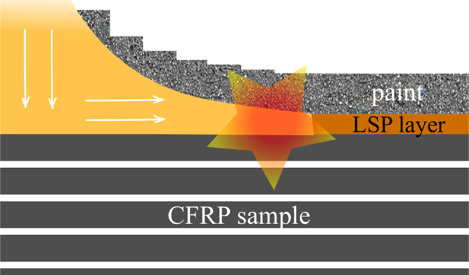
2. Confinement of the surface explosion. Due to Joule effect, the metallic protection below the paint layer vaporises rapidly, creating a surface explosion. However, ejection of the paint is slower than the explosion propagation in the LSP layer (Fig. 1). This creates a confinement effect that enhances the shock wave generated by the explosion, leading to additional damage [Reference Lepetit, Escure, Guinard, Revel, Peres and Duval5, Reference Bigand9]. Therefore, the parameters that will affect the overpressure enhancement are the paint density and thickness. The thickness of the panel does not have influence on the surface phenomena [Reference Murillo, Flourens, Garcia, Duval and Cavaliere7].
Illustration of paint confinement of the surface explosion [Reference Bigand9].

In a protected carbon fibre-reinforced polymer (CFRP) subjected to a transient lightning current, the induced damage can be separated in two kinds: thermal surface damage and structural damage. The former is mainly due to the thermal-electrical effects of the lightning current in the LSP layer and in the composite [Reference Lepetit, Escure, Guinard, Revel, Peres and Duval5, Reference Soulas10]. Employing copper mesh or other, metallic or non-metallic LSP with sufficient in-plane conductivity can significantly reduce thermal damage depth by reducing the temperature rise in the plies below the LSP layer [Reference Lee, Lacy, Pittman and Mazzola11–Reference Zhang, Zhang, Cheng and Huang15]. Thermal damage then remains confined to the LSP layer and eventually the very first few plies. Therefore, the surface damage can be measured by visual inspection, where vaporisation of the LSP layer and ejection of the paint, dry fibres (tufting) due to resin deterioration and broken fibres can be observed [Reference Bigand9]. On the other hand, the assessment of structural damage needs a specialised procedure. Common inspection techniques include ultrasonic C-scan [Reference Hirano, Katsumata, Iwahori and Todoroki16] or X-ray [Reference Ackermann17] analysis to measure delamination, which has a mechanical origin [Reference Soulas10].
Several studies have already been reported about the influence of the paint thickness on lightning damage, including composite and aluminium structures in aircraft. It is clear that the type and the thickness of the paint layer are among the most important factors of the damage induced by the mechanical loads of lightning strikes to aircraft structures of a predefined lay-up [Reference Kumar, Yokozeki, Karch, Hassen, Hershey, Kim, Lindahl, Barnes, Bandari and Kunc8, Reference Soulas10, Reference Bigand, Espinosa and Bauchire18].
Lepetit et al. [Reference Lepetit, Escure, Guinard, Revel, Peres and Duval5] showed that the paint layer enhances the shock waves due to the concentrated arc, with a detrimental effect on the damage caused by lightning strikes. The experiments, supported by high-speed camera analysis, showed that an explosion occurred on the surface due to the rapid vaporisation of the LSP layer. Similarly, Bigand et al. [Reference Bigand, Espinosa and Bauchire18] performed specific tests that demonstrate the expansion of the lightning arc and hot gases, the shock front propagation from the lightning arc and the ejection of pieces of paint.
Bigand and Duval [Reference Bigand and Duval2] showed that the damage extent in thin CFRP laminate panels protected with expanded copper foil (ECF) increases with increasing paint thickness. Murillo et al. [Reference Murillo, Flourens, Garcia, Duval and Cavaliere7] showed that a variation of the paint thickness can lead to an increase of the size of damage induced by simulated lightning strike. The same work [Reference Murillo, Flourens, Garcia, Duval and Cavaliere7] also proved the importance of paint thickness on the mechanical loads suffered by the panel, with a thicker paint layer leading to a faster deflection of the panel.
A few more authors studied the paint thickness effect using aluminium panels [Reference Chemartin, Lalande, Peyrou, Chazottes, Elias, Delalondre, Cheron and Lago19–Reference Moupfouma21]. For example, Chemartin et al. [Reference Chemartin, Lalande, Peyrou, Chazottes, Elias, Delalondre, Cheron and Lago19] studied aluminium and composite panels and, in both cases, a correlation was found between the increase of damage extent and the increase of paint thickness of the tested panels. Surface damage was identified in thinner paint layers, while the panel was punctured for thicker paint layers. Lago [Reference Lago20] used stereo digital image correlation to study the paint thickness effect on the deformation, showing that the thicker the paint layer, the larger the deflection.
Lepetit et al. [Reference Lepetit, Escure, Guinard, Revel, Peres and Duval5] developed the first model for the overpressure that considered the confinement effect due to the paint layer, which was then improved by Karch et al. [Reference Karch, Honke, Steinwandel and Dittrich4]. In this approach, the paint is considered as a mass, which leads to an inertial effect on the overpressure occurring on the surface. Alternatively, Espinosa et al. [Reference Espinosa, Montel, Pons, Lachaud and Soulas22] used thermal-mechanical numerical simulations to assess the effect of an overpressure due to the presence of paint on the damage suffered by the composite. The paint confinement contribution was simulated by an equivalent pressure.
As the industry moves towards design and certification by analysis processes, the ability to accurately capture the effects of product design options, such as the lay-up of the laminate but also the type and thickness of the paint system applied on the surface of the structure, in the context of lightning strike damage tolerance becomes crucial [Reference Xu, Millen, Lee, Abdelal, Mitchard, Wisnom and Murphy23, Reference Millen, Xu, Lee, Mukhopadhyay, Wisnom and Murphy24]. For instance, painting of the CFRP is recommended by Kumar et al. [Reference Kumar, Yokozeki, Karch, Hassen, Hershey, Kim, Lindahl, Barnes, Bandari and Kunc8] to demonstrate the effectiveness of an LSP for actual application. The same must be considered when developing analysis methods for CFRP subjected to lightning strikes.
Therefore, in this work, physically based models of the mechanical loads induced by lightning strikes [Reference Karch, Arteiro and Camanho25] are employed in the generation of the mechanical overpressure fields due to a simulated lightning strike, while accounting for the effect of paint thickness without paint-thickness calibration. These fields are then implemented into a three-dimensional (3D) finite element framework and combined with a continuum damage mechanics model for CFRPs [Reference Furtado, Catalanotti, Arteiro, Gray, Wardle and Camanho26] to predict the effect of paint thickness on the mechanical damage in composite structures subjected to this type of events. Unpainted structures and three different paint thicknesses are considered in the analyses and correlated with data from literature and from industry for unpainted and painted structures.
2.0 Mechanical lightning loads
In protected CFRP subjected to a transient lightning current, the shock waves generated by the exploding vaporised materials at the arc attachment area (or within the material volume extremely heated by the generated Joule heat) confined between the composite material and the paint layer are the main contribution to lightning-induced mechanical damage [Reference Karch, Honke, Steinwandel and Dittrich4, Reference Lepetit, Escure, Guinard, Revel, Peres and Duval5, Reference Duval, Lepetit, Revel and Peres27, Reference Wulbrand and Karch28] (see the generated mechanical impulses in Figs 4 and 5). It should be noted that due to the extremely high energy density of a lightning strike at the arc root area, an extremely short evaporation of the material cannot be avoided, which then leads to an explosion and ultimately the generation of shock waves. However, the contributions from the shock waves caused by the supersonic expansion of the hot plasma channel [Reference Karch, Honke, Steinwandel and Dittrich4, Reference Plooster29–Reference Karch, Wulbrand and Müller31] and the magnetic volume forces (magnetic pressures) caused by the impressed current flow in the electrically conducting structures [Reference Karch, Honke, Steinwandel and Dittrich4, Reference Karch and Wulbrand32] cannot be neglected (see Section 5), especially in the unpainted cases. Because the presence of the LSP layer minimises thermal damage and temperature rise in the underlying plies [Reference Millen, Murphy, Abdelal and Catalanotti13], in a first approximation, thermal and thermal-mechanical effects can be neglected [Reference Pedro, Gonçalves, Soares, Arteiro, Honke and Karch33].
2.1 Root radius
The root radius expansion ${R_R}(t)$
is calculated using the finite volume degradation approach [Reference Karch, Arteiro and Camanho25]. The root radius data computed by Karch et al. [Reference Karch, Arteiro and Camanho25] for two protected CFRP with different expanded copper foils (ECFs) – 2Cu4-100FA, with a surface weight of 73.3 g/m
${R_R}(t)$
is calculated using the finite volume degradation approach [Reference Karch, Arteiro and Camanho25]. The root radius data computed by Karch et al. [Reference Karch, Arteiro and Camanho25] for two protected CFRP with different expanded copper foils (ECFs) – 2Cu4-100FA, with a surface weight of 73.3 g/m ${{\rm{\;}}^2}$
(ECF 73), and 3Cu7-100FA, with a surface weight of 195.3 g/m
${{\rm{\;}}^2}$
(ECF 73), and 3Cu7-100FA, with a surface weight of 195.3 g/m ${{\rm{\;}}^2}$
(ECF 195) – are fitted using a double exponential function:
${{\rm{\;}}^2}$
(ECF 195) – are fitted using a double exponential function:
 \begin{equation}{R_R}(t) = \begin{cases}{{R_{{R_0}}} + a\big( {{e^{\alpha t}} - {e^{\beta t}}} \big),} & {}t \le {t_s}\\{c,} & {}{t \gt {t_s}}\end{cases} \end{equation}
with ${R_{{R_0}}} = $
0.5 mm ensuring an initial arc root radius of 0.5 mm independently of the parameters
${R_{{R_0}}} = $
0.5 mm ensuring an initial arc root radius of 0.5 mm independently of the parameters $a$
,
$a$
, $\alpha $
and
$\alpha $
and $\beta $
, which are obtained by curve fitting of the finite volume results [Reference Karch, Arteiro and Camanho25].
$\beta $
, which are obtained by curve fitting of the finite volume results [Reference Karch, Arteiro and Camanho25].
2.2 Near-surface explosion of the lightning protection layer
The explosion of the LSP layer is assumed to be caused mainly by the rapid vaporisation of the metallic mesh of the LSP layer due to Joule resistive heating and direct heat transfer from the plasma channel at the arc root area. It is assumed that the spatial distribution of the expanding plasma pressure can be approximated by a Gaussian bell-shaped curve:
 \begin{equation}{p_e}( {r,t} ) = {p_e}(t){\rm{\;\;}}{k^{ - 2}}{\rm{\;\;exp}}\left[ { - \frac{{{r^2}}}{{{{( {k{\rm{\;\;}}{R_R}(t)} )}^2}}}} \right]\end{equation}
where the effective plasma overpressure ${p_e}(t)$
is numerically determined as described by Karch et al. [Reference Karch, Arteiro and Camanho25]. The parameter
${p_e}(t)$
is numerically determined as described by Karch et al. [Reference Karch, Arteiro and Camanho25]. The parameter $k \lt 1$
in Equation (2) is used to limit the pressure distribution mainly to the arc root area
$k \lt 1$
in Equation (2) is used to limit the pressure distribution mainly to the arc root area $\pi R_R^2(t)$
by controlling the shape of the Gaussian curve.
$\pi R_R^2(t)$
by controlling the shape of the Gaussian curve.
2.3 Supersonic plasma expansion
A supersonic shock wave is created by the overpressure caused by the rapid temperature rise of the plasma channel. Following Lin’s approach [Reference Lin34], the shock wave expands radially according to the following equation [Reference Karch, Arteiro and Camanho25]:
 \begin{equation}R(t) \cong {\begin{cases}{1.004{{\left( {\dfrac{{{E_0}}}{{{\rho _0}}}} \right)}^{0.25}}\sqrt {0.5}}\, {}, & t \lt 0.5\ \mu s\\[8pt]{1.004{{\left( {\dfrac{{{E_0}}}{{{\rho _0}}}} \right)}^{0.25}}\sqrt t }\, {}, & t \ge 0.5\ \mu s\end{cases}} ,\end{equation}
where ${E_0}$
is the initial channel energy density and
${E_0}$
is the initial channel energy density and ${\rho _0}$
the initial mass (air) density. The following relationship between the initial channel energy density
${\rho _0}$
the initial mass (air) density. The following relationship between the initial channel energy density ${E_0}$
(J/m) and the lightning current peak
${E_0}$
(J/m) and the lightning current peak ${I_{{\rm{max}}}}$
(A) can be established [Reference Karch, Wulbrand and Müller31, Reference Karch, Schreiner, Honke and Wolfrum35]:
${I_{{\rm{max}}}}$
(A) can be established [Reference Karch, Wulbrand and Müller31, Reference Karch, Schreiner, Honke and Wolfrum35]:
 \begin{equation}{E_0} \cong 0.45 \times {10^{ - 2}}{\rm{\;}}{( {{I_{{\rm{max}}}}} )^{1.25}}\end{equation}
Finally, the shock wave pressure is described by:
 \begin{equation}p( {\eta ,t} ) \cong {\begin{cases}{\beta \cdot t} {}, & t \lt 0.5\, \mu s\\[3pt]{0.180{{\left( {{\rho _0}{E_0}} \right)}^{0.5}}f( \eta ){\rm{\;}}{t^{ - 1}} - 1} {}, & t \ge 0.5\, \mu s\\[3pt]0 {}, & t \gt 100\, \mu s\end{cases}}\!,\end{equation}
where $\beta $
ensures a linear evolution of the pressure with time before the radial shock wave detaches from the hot, overpressured lightning channel,
$\beta $
ensures a linear evolution of the pressure with time before the radial shock wave detaches from the hot, overpressured lightning channel, $f( \eta )$
is a dimensionless pressure function and
$f( \eta )$
is a dimensionless pressure function and $\eta = r/R(t)$
is the dimensionless radius [Reference Karch, Wulbrand and Müller31].
$\eta = r/R(t)$
is the dimensionless radius [Reference Karch, Wulbrand and Müller31].
2.4 Magnetic forces
The current flow in the LSP layer creates a magnetic pressure whose amplitude depends on whether it lies inside ( $0 \lt r \lt {R_R}(t)$
) or outside the arc root radius (
$0 \lt r \lt {R_R}(t)$
) or outside the arc root radius ( $r \gt {R_R}(t)$
) [Reference Karch, Arteiro and Camanho25]. Taking this into account, the effective magnetic surface pressure acting on the upper side of the LSP layer is given as:
$r \gt {R_R}(t)$
) [Reference Karch, Arteiro and Camanho25]. Taking this into account, the effective magnetic surface pressure acting on the upper side of the LSP layer is given as:
 \begin{equation}{p_{\rm{m}}}( {r,t} ) = {\begin{cases}{\dfrac{{{\mu _r}{\rm{\;}}{\mu _0}{\rm{\;}}J{{(t)}^2}}}{{8{\pi ^2}}}\dfrac{{{r^2}}}{{R_R^4(t)}}} {}, {}&0 \lt r \lt {R_R}(t)\\[9pt]{\dfrac{{{\mu _r}{\rm{\;}}{\mu _0}{\rm{\;}}J{{(t)}^2}}}{{8{\pi ^2}{r^2}}}} {}, {}&r \gt {R_R}(t)\end{cases}} \end{equation}
where ${\mu _0} = 4\pi \times {10^{ - 7}}$
Hm
${\mu _0} = 4\pi \times {10^{ - 7}}$
Hm ${{\rm{\;}}^{ - 1}}$
is the permeability of the free space,
${{\rm{\;}}^{ - 1}}$
is the permeability of the free space, ${\mu _r} = 1$
is the relative permeability of the non-magnetic LSP layer, and
${\mu _r} = 1$
is the relative permeability of the non-magnetic LSP layer, and $J(t)$
is the total lightning current amplitude [Reference Karch, Arteiro and Camanho25].
$J(t)$
is the total lightning current amplitude [Reference Karch, Arteiro and Camanho25].
3.0 Composite damage model
A modification [Reference Furtado, Catalanotti, Arteiro, Gray, Wardle and Camanho26] to the continuum damage mechanics model proposed by Maimí et al. [Reference Maimí, Camanho, Mayugo and Dávila36, Reference Maimí, Camanho, Mayugo and Dávila37] is implemented in a user-defined subroutine VUMAT for the commercial explicit finite element solver Abaqus/Explicit [38] to model failure of the composite plies. Each ply, which is assumed transversely isotropic, must be represented explicitly in the finite element model. To account for ply thickness effects, in-situ strengths are defined as a function of ply thickness [Reference Furtado, Catalanotti, Arteiro, Gray, Wardle and Camanho26, Reference Camanho, Dávila, Pinho, Iannucci and Robinson39]. Therefore, adjacent plies with the same fibre orientation are modelled by a single element through the thickness [Reference Arteiro, Gray and Camanho40].
Bilinear softening laws are employed to model longitudinal damage growth in tension and in compression (according to the parameters ${\,f_{\mathcal{G}1 + }}$
,
${\,f_{\mathcal{G}1 + }}$
, ${\,f_{XT}}$
and
${\,f_{XT}}$
and ${\,f_{XC}}$
). To represent the effects of hydrostatic pressure [Reference Camanho, Arteiro, Melro, Catalanotti and Vogler41], the in-plane shear strength
${\,f_{XC}}$
). To represent the effects of hydrostatic pressure [Reference Camanho, Arteiro, Melro, Catalanotti and Vogler41], the in-plane shear strength ${S_L}$
, the fracture toughness for longitudinal compression (
${S_L}$
, the fracture toughness for longitudinal compression ( ${\mathcal{G}_{1 - }}$
) and the longitudinal compressive strength ratio at the inflection point (
${\mathcal{G}_{1 - }}$
) and the longitudinal compressive strength ratio at the inflection point ( ${\,f_{XC}}$
) are scaled as a function of the applied hydrostatic pressure [Reference Furtado, Catalanotti, Arteiro, Gray, Wardle and Camanho26]. In addition, the fracture toughness for in-plane shear (
${\,f_{XC}}$
) are scaled as a function of the applied hydrostatic pressure [Reference Furtado, Catalanotti, Arteiro, Gray, Wardle and Camanho26]. In addition, the fracture toughness for in-plane shear ( ${\mathcal{G}_6}$
) is scaled to account for the effect of transverse compressive stresses on the fracture toughness associated with in-plane shear fracture [Reference Furtado, Catalanotti, Arteiro, Gray, Wardle and Camanho26].
${\mathcal{G}_6}$
) is scaled to account for the effect of transverse compressive stresses on the fracture toughness associated with in-plane shear fracture [Reference Furtado, Catalanotti, Arteiro, Gray, Wardle and Camanho26].
To ensure mesh-independent results after damage onset, an energy regularisation approach based on the fracture energy associated to each failure mechanism and based on the characteristic length of the finite elements is used [Reference Furtado, Catalanotti, Arteiro, Gray, Wardle and Camanho26, Reference Bažant and Oh42].
Delamination between plies is modelled using the interaction properties with cohesive behaviour available in Abaqus [38]. The cohesive interaction is defined by a bilinear traction-separation damage law accounting for mode dependency according to the B-K law [Reference Benzeggagh and Kenane43], and the onset of interlaminar damage is predicted by a quadratic stress-based criterion. A friction coefficient of 0.3 is assumed [Reference Arteiro, Gray and Camanho40].
The continuum damage mechanics and cohesive zone models [Reference Furtado, Catalanotti, Arteiro, Gray, Wardle and Camanho26, Reference Arteiro, Gray and Camanho40] employed in this work do not include strain rate effects. Although the authors recognise that strain rate effects would be required for higher fidelity of the mechanical response predictions, and despite the availability of strain rate-dependent formulations in literature [Reference Rodrigues Lopes, Camanho, Andrade Pires and Arteiro44, Reference Cózar, Maimí, González, Camanho and Otero45], in the present work, the authors opted for employing a composite damage model that has been thoroughly validated in the past [Reference Furtado, Catalanotti, Arteiro, Gray, Wardle and Camanho26, Reference Pedro, Gonçalves, Soares, Arteiro, Honke and Karch33, Reference Arteiro, Gray and Camanho40, Reference Ni, Kopp, Kalfon-Cohen, Furtado, Lee, Arteiro, Borstnar, Mavrogordato, Helfen, Sinclair, Spearing, Camanho and Wardle46–Reference Vallmajó, Descamps, Arteiro and Turon48] before moving to newer formulations.
4.0 Composite material, coupon geometry and finite element model
Following Lepetit et al. [Reference Lepetit, Escure, Guinard, Revel, Peres and Duval5], CFRP samples made from eight T700/M21 unidirectional (UD) plies with a quasi-isotropic [45/0/–45/90] $_{\rm{S}}$
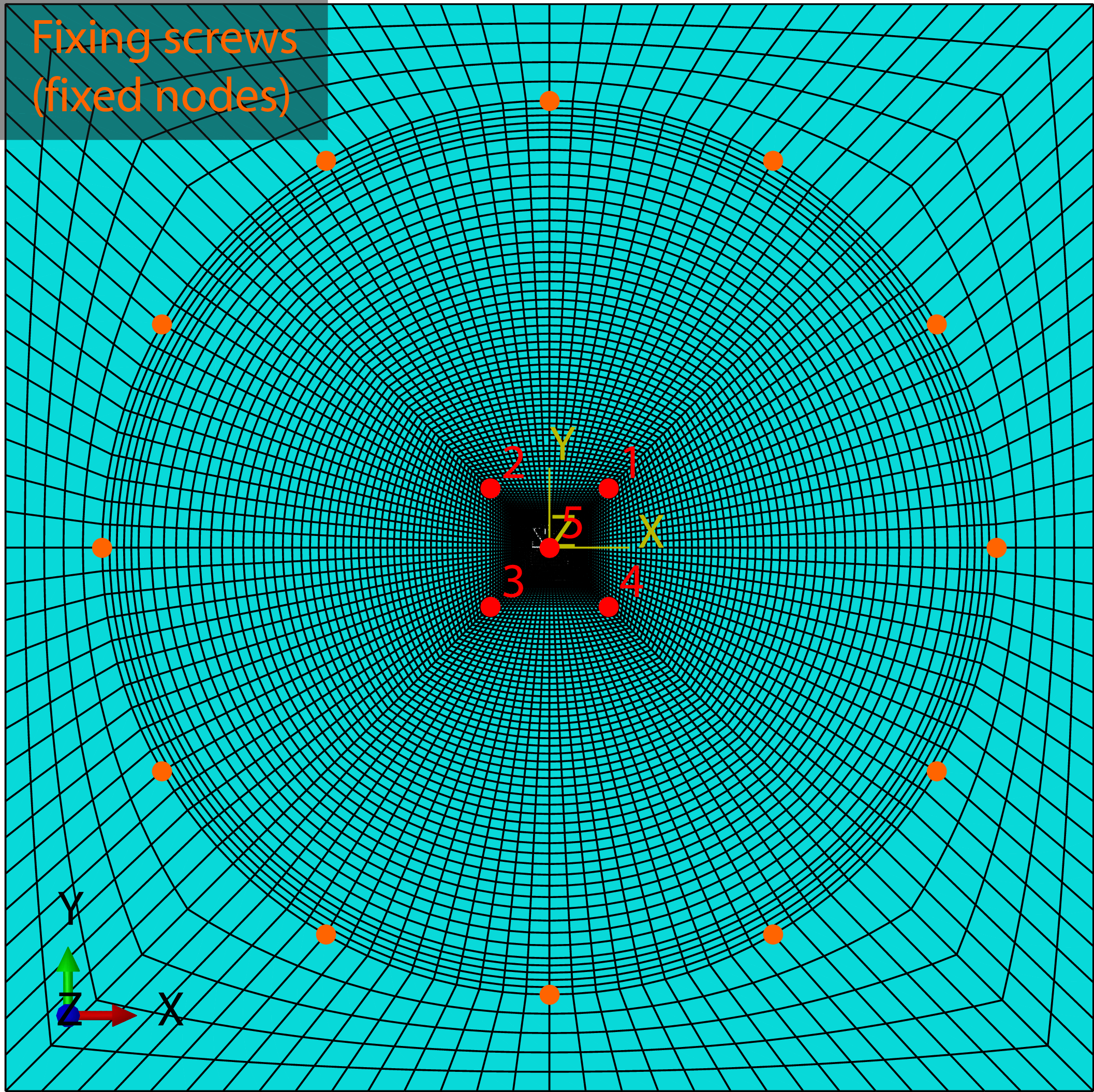
lay-up are considered in this study. Each T700/M21 UD ply is 0.262 mm thick. Two sets of samples were tested by Lepetit et al. [Reference Lepetit, Escure, Guinard, Revel, Peres and Duval5], protected using ECF 73 and ECF 195, respectively. The samples were subjected to standard arc attachment tests, with a lightning waveform of D type. The experimental setup included a very fast camera (1,000,000 fps) filtered to avoid saturation of the sensors by the light emitted by the electrical arc in the front face of the sample, where the lightning discharge is applied. In the back face, Doppler interferometry (or velocity interferometer system for any reflector – VISAR) was applied to measure deflection of the sample. Five VISAR sensors were used to measure the displacement speed on different points of the sample, located on a square with 49 mm-long sides (illustrated in the finite element mesh in Fig. 2). Sensor 5 (IDF5) was positioned in line with the position of the electrode, on the opposite face. A polyurethane paint system with a thickness of 200
$_{\rm{S}}$
lay-up are considered in this study. Each T700/M21 UD ply is 0.262 mm thick. Two sets of samples were tested by Lepetit et al. [Reference Lepetit, Escure, Guinard, Revel, Peres and Duval5], protected using ECF 73 and ECF 195, respectively. The samples were subjected to standard arc attachment tests, with a lightning waveform of D type. The experimental setup included a very fast camera (1,000,000 fps) filtered to avoid saturation of the sensors by the light emitted by the electrical arc in the front face of the sample, where the lightning discharge is applied. In the back face, Doppler interferometry (or velocity interferometer system for any reflector – VISAR) was applied to measure deflection of the sample. Five VISAR sensors were used to measure the displacement speed on different points of the sample, located on a square with 49 mm-long sides (illustrated in the finite element mesh in Fig. 2). Sensor 5 (IDF5) was positioned in line with the position of the electrode, on the opposite face. A polyurethane paint system with a thickness of 200 ${\rm{\mu }}$
m was applied to each sample over a surfacing film of 127
${\rm{\mu }}$
m was applied to each sample over a surfacing film of 127 ${\rm{\mu }}$
m. Assuming that part of the film fills the surface roughness, a 300
${\rm{\mu }}$
m. Assuming that part of the film fills the surface roughness, a 300 ${\rm{\mu }}$
m dielectric coating (paint) layer is assumed in this study.
${\rm{\mu }}$
m dielectric coating (paint) layer is assumed in this study.
Composite plate finite element mesh.

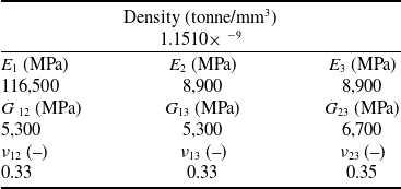
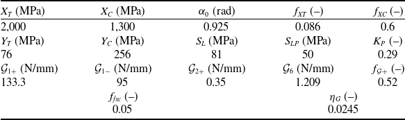
Tables 1 and 2 show, respectively, the UD ply elastic properties and the strength and material degradation properties used in the simulations, including the in-plane yield stress and shear modulus degradation factor ( ${S_{LP}}$
and
${S_{LP}}$
and ${K_P}$
), the longitudinal tensile and compressive plain strengths (
${K_P}$
), the longitudinal tensile and compressive plain strengths ( ${X_T}$
and
${X_T}$
and ${X_C}$
), the UD transverse tensile and compressive strengths (
${X_C}$
), the UD transverse tensile and compressive strengths ( ${Y_T}$
and
${Y_T}$
and ${Y_C}$
), the assumed composite fracture angle in uniaxial transverse compression (
${Y_C}$
), the assumed composite fracture angle in uniaxial transverse compression ( ${\alpha _0}$
), the UD in-plane shear strength (
${\alpha _0}$
), the UD in-plane shear strength ( ${S_L}$
), the longitudinal tensile fracture toughness and the fraction of the fracture toughness dissipated in the second arm of the bilinear softening law (
${S_L}$
), the longitudinal tensile fracture toughness and the fraction of the fracture toughness dissipated in the second arm of the bilinear softening law ( ${\mathcal{G}_{1 + }}$
and
${\mathcal{G}_{1 + }}$
and ${\,f_{\mathcal{G}1 + }}$
), the longitudinal compressive, transverse tensile and in-plane shear fracture toughness (
${\,f_{\mathcal{G}1 + }}$
), the longitudinal compressive, transverse tensile and in-plane shear fracture toughness ( ${\mathcal{G}_{1 - }}$
,
${\mathcal{G}_{1 - }}$
, ${\mathcal{G}_{2 + }}$
and
${\mathcal{G}_{2 + }}$
and ${\mathcal{G}_6}$
), the frictional parameter (
${\mathcal{G}_6}$
), the frictional parameter ( ${\,f_{fxc}}$
) used to scale the crushing (compression) strength factor (
${\,f_{fxc}}$
) used to scale the crushing (compression) strength factor ( ${\,f_{XC}}$
) as a function of the hydrostatic pressure [Reference Furtado, Catalanotti, Arteiro, Gray, Wardle and Camanho26]:
${\,f_{XC}}$
) as a function of the hydrostatic pressure [Reference Furtado, Catalanotti, Arteiro, Gray, Wardle and Camanho26]:
 \begin{equation}f_{XC}^{ef} = {\rm{min}}\{ {1,{\,f_{XC}}( {1 - {\,f_{fxc}} \langle -{I_3}\rangle} )} \},{\rm{\;\;\;\;}}{I_3} = {\sigma _{22}} + {\sigma _{33}}\end{equation}
and the material dependent empirically derived enhancement factor ( ${\eta _G}$
) used in the definition of the effective fracture toughness for in-plane shear in the presence of transverse compressive stresses [Reference Furtado, Catalanotti, Arteiro, Gray, Wardle and Camanho26]:
${\eta _G}$
) used in the definition of the effective fracture toughness for in-plane shear in the presence of transverse compressive stresses [Reference Furtado, Catalanotti, Arteiro, Gray, Wardle and Camanho26]:
 \begin{equation}\mathcal{G}_6^{ef} = {\mathcal{G}_6}( {1 - {\eta _G} \langle- {\sigma _{22}}}\rangle )\end{equation}
T700/M21 UD ply density, Young’s moduli, shear moduli and Poisson’s ratios

T700/M21 strengths and material degradation properties [Reference Huchette50–Reference Charrier53] used in the continuum damage mechanics model [Reference Furtado, Catalanotti, Arteiro, Gray, Wardle and Camanho26]

Table 3 shows the interlaminar properties used in the simulations, including the stiffness of the cohesive surfaces before damage onset ( $K$
) and the mixed-mode parameter of the B-K law (
$K$
) and the mixed-mode parameter of the B-K law ( ${\eta _{B - K}}$
) [Reference Benzeggagh and Kenane43]. The shear strengths (
${\eta _{B - K}}$
) [Reference Benzeggagh and Kenane43]. The shear strengths ( ${\tau _1} = {\tau _2}$
) are determined as a function of the mode I and mode II fracture toughness (
${\tau _1} = {\tau _2}$
) are determined as a function of the mode I and mode II fracture toughness ( ${\mathcal{G}_{Ic}}$
and
${\mathcal{G}_{Ic}}$
and ${\mathcal{G}_{IIc}}$
), and the normal strength (
${\mathcal{G}_{IIc}}$
), and the normal strength ( ${\tau _3}$
) [Reference Turon, Camanho, Costa and Renart49]:
${\tau _3}$
) [Reference Turon, Camanho, Costa and Renart49]:
 \begin{equation}{\tau _1} = {\tau _2} = {\tau _3}\sqrt {\frac{{{\mathcal{G}_{IIc}}}}{{{\mathcal{G}_{Ic}}}}} \end{equation}
T700/M21 interlaminar properties

The effective properties of the LSP layers ECF 73 and ECF 195 filled with epoxy resin M21 were determined using a micro-mechanical finite element homogenisation approach by Karch et al. [Reference Karch, Arteiro and Camanho25]. The properties used in the simulations are given in Table 4.
Effective properties of ECF 73 and ECF 195 filled with epoxy resin M21

The tested samples are square laminated plates (450 mm-long sides) supported on a fixed plate with a circular opening (340 mm diameter), fixed using screws placed along a circumference concentric with the central opening of the support plate (370 mm diameter). The CFRP sample is modelled fixing the out-of-plane displacements on the supported area outside the circular opening and fixing the nodes along the circumference where the screws are placed (Fig. 2). The finite element mesh used in this study was carefully chosen to ensure that the local response below the impact point is accurately captured, especially in the initial nanoseconds corresponding to the peak value of the overpressure caused by the explosion of the LSP layer (see Fig. 3) within a very small region (expanding arc root) [Reference Pedro, Gonçalves, Soares, Arteiro, Honke and Karch33]. The 8-node C3D8R 3D brick elements with reduced integration are used to model each layer of the composite structure under consideration, including the LSP layer. It is assumed that, due to its soft behaviour, the stiffness and strength of the paint is negligible, and therefore it is not explicitly represented in the finite element model, but implicitly accounted for in the computed overpressure caused by the explosion of the surface conducting materials.
Calculated overpressure caused by the explosion of the LSP layers as a function of time.

5.0 Lightning current and lightning loads implementation
To represent the measured lightning transient D current waveform tested by Lepetit et al. [Reference Lepetit, Escure, Guinard, Revel, Peres and Duval5], a modified double exponential function was proposed by Karch et al. [Reference Karch, Arteiro and Camanho25]:
 \begin{equation}J(t) = {\begin{cases}{c( {{e^{ - at}} - {e^{ - bt}}} )} {}, & {}{t \lt {t_{{\rm{max}}}}}\\[3pt]{c( {{e^{ - af( {t - \nu} )}} - {e^{ - bf( {t - \nu} )}}} )} {},& {}{t \ge {t_{{\rm{max}}}}}\end{cases}} \end{equation}
where ${t_{{\rm{max}}}}$
is the time at the current peak. The parameters for the D current waveform with a time to peak of 26.8
${t_{{\rm{max}}}}$
is the time at the current peak. The parameters for the D current waveform with a time to peak of 26.8 ${\rm{\mu }}$
s, a decay time of 48.5
${\rm{\mu }}$
s, a decay time of 48.5 ${\rm{\mu }}$
s and a peak current of 96.4 kA [Reference Lepetit, Escure, Guinard, Revel, Peres and Duval5] are summarised in Table 5.
${\rm{\mu }}$
s and a peak current of 96.4 kA [Reference Lepetit, Escure, Guinard, Revel, Peres and Duval5] are summarised in Table 5.
Waveform parameters for the 26.8/48.5 ${\rm{\mu }}$
s, 96.4 kA modified double exponential function
${\rm{\mu }}$
s, 96.4 kA modified double exponential function

This modified D current waveform [Reference Lepetit, Escure, Guinard, Revel, Peres and Duval5] is then used to calculate the root radii, following Karch et al. [Reference Karch, Arteiro and Camanho25]. The parameters of the fitting function in Equation (1) are obtained using the curve fitting application from MATLAB. These parameters are shown in Table 6.
Parameters for root radius fitting of the correct transient D current waveform with a time to peak of 26.8 ${\rm{\mu }}$
s, a decay time of 48.5
${\rm{\mu }}$
s, a decay time of 48.5 ${\rm{\mu }}$
s and a peak current of 96.4 kA [Reference Lepetit, Escure, Guinard, Revel, Peres and Duval5]
${\rm{\mu }}$
s and a peak current of 96.4 kA [Reference Lepetit, Escure, Guinard, Revel, Peres and Duval5]

The effective overpressure caused by the explosion of the LSP layer is directly dependent on the root radius. Therefore, the pressure magnitudes for the two ECFs are determined considering the same transient D current waveform [Reference Lepetit, Escure, Guinard, Revel, Peres and Duval5]. The effective plasma overpressure is generated considering protected CFRP without paint and with a paint thickness (dielectric coating) of 200, 300 and 400 ${\rm{\mu }}$
m. Figure 3 shows the effective plasma overpressure determined following the approach proposed by Karch et al. [Reference Karch, Arteiro and Camanho25], with the parameter
${\rm{\mu }}$
m. Figure 3 shows the effective plasma overpressure determined following the approach proposed by Karch et al. [Reference Karch, Arteiro and Camanho25], with the parameter $k$
in Equation (2) set to 0.4 and 0.1 for ECF 73 and ECF 195, respectively. This parameter was selected based on the available experimental data for a paint thickness of 300
$k$
in Equation (2) set to 0.4 and 0.1 for ECF 73 and ECF 195, respectively. This parameter was selected based on the available experimental data for a paint thickness of 300 ${\rm{\mu }}$
m [Reference Lepetit, Escure, Guinard, Revel, Peres and Duval5, Reference Karch, Arteiro and Camanho25] and a sensitivity analysis using the composite damage model and the finite element model presented respectively in Sections 3 and 4. It is important to emphasise that parameter
${\rm{\mu }}$
m [Reference Lepetit, Escure, Guinard, Revel, Peres and Duval5, Reference Karch, Arteiro and Camanho25] and a sensitivity analysis using the composite damage model and the finite element model presented respectively in Sections 3 and 4. It is important to emphasise that parameter $k$
is fitted for each LSP layer considering the results for just one case (with a defined paint thickness), since
$k$
is fitted for each LSP layer considering the results for just one case (with a defined paint thickness), since $k$
is assumed to be mainly dependent on the properties of the LSP layer, and not the paint thickness; no other parameter in Section 2 is calibrated to fit velocity or deflection test data. Figure 4 shows the impulses generated by the explosion of the LSP layers as a function of time considering the protected CFRPs with ECF 73 and ECF 195, without paint and with a paint thickness of 200, 300 and 400
$k$
is assumed to be mainly dependent on the properties of the LSP layer, and not the paint thickness; no other parameter in Section 2 is calibrated to fit velocity or deflection test data. Figure 4 shows the impulses generated by the explosion of the LSP layers as a function of time considering the protected CFRPs with ECF 73 and ECF 195, without paint and with a paint thickness of 200, 300 and 400 ${\rm{\mu }}$
m. As can be observed in Figs 3 and 4, independently of the LSP layer, the overpressure and, consequently, the impulse due to the explosion of the LSP layers are mostly negligible if the structure is unpainted. The presence of paint leads to significantly higher loading, whose magnitude increases with increasing paint thickness.
${\rm{\mu }}$
m. As can be observed in Figs 3 and 4, independently of the LSP layer, the overpressure and, consequently, the impulse due to the explosion of the LSP layers are mostly negligible if the structure is unpainted. The presence of paint leads to significantly higher loading, whose magnitude increases with increasing paint thickness.
Calculated impulse caused by the explosion of the LSP layers as a function of time.

The supersonic plasma expansion overpressure is determined using the peak current ${I_{{\rm{max}}}}$
of the transient D current waveform [Reference Lepetit, Escure, Guinard, Revel, Peres and Duval5] in Equation (4). In this case,
${I_{{\rm{max}}}}$
of the transient D current waveform [Reference Lepetit, Escure, Guinard, Revel, Peres and Duval5] in Equation (4). In this case, ${\rm{\beta }} = 392.2952$
bar/
${\rm{\beta }} = 392.2952$
bar/ ${\rm{\mu }}$
s. Because the supersonic plasma expansion overpressure is just a function of the current amplitude, its contribution to mechanical loads is the same independently of the LSP layer used.
${\rm{\mu }}$
s. Because the supersonic plasma expansion overpressure is just a function of the current amplitude, its contribution to mechanical loads is the same independently of the LSP layer used.
To determine the pressure due to the magnetic forces given by Equation (6), the total lightning current amplitude $J(t)$
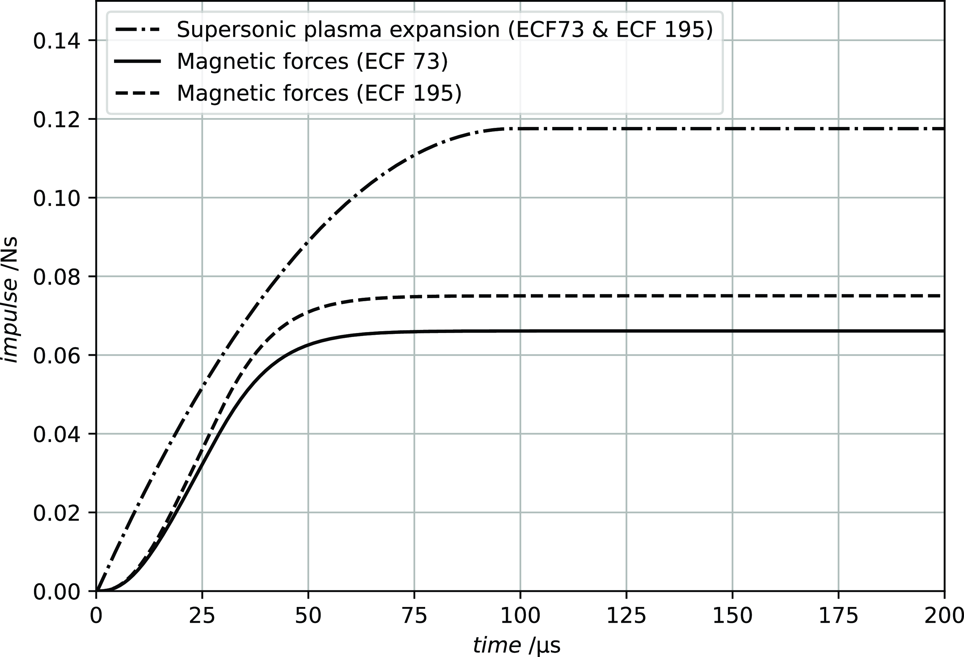
approximated by the modified double exponential function in Equation (10) is used [Reference Karch, Arteiro and Camanho25]. Figure 5 shows the impulses generated by the supersonic plasma expansion and by the magnetic forces. Compared with the impulses caused by the explosion of the LSP layers in Fig. 4, it is clear that all contributions are comparable in the case of unpainted structures. In the case of painted structures, and for the paint thicknesses considered in this study, the effects of the supersonic plasma expansion and of the magnetic forces (Fig. 5) are lower than the effects of the explosion of the LSP layer (Fig. 4), which has the highest contribution to the mechanical lightning loads. Nevertheless, and even in the case of painted structures, the supersonic plasma expansion and the magnetic forces cannot be neglected.
$J(t)$
approximated by the modified double exponential function in Equation (10) is used [Reference Karch, Arteiro and Camanho25]. Figure 5 shows the impulses generated by the supersonic plasma expansion and by the magnetic forces. Compared with the impulses caused by the explosion of the LSP layers in Fig. 4, it is clear that all contributions are comparable in the case of unpainted structures. In the case of painted structures, and for the paint thicknesses considered in this study, the effects of the supersonic plasma expansion and of the magnetic forces (Fig. 5) are lower than the effects of the explosion of the LSP layer (Fig. 4), which has the highest contribution to the mechanical lightning loads. Nevertheless, and even in the case of painted structures, the supersonic plasma expansion and the magnetic forces cannot be neglected.
Calculated impulse caused by the supersonic plasma expansion and by the magnetic forces as a function of time.

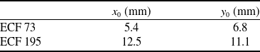
Following Karch et al. [Reference Karch, Arteiro and Camanho25], the mechanical pressure fields resulting from the near-surface explosion of the LSP layer, from the supersonic plasma expansion and from the magnetic field caused by the impressed current flow in the electrically conducting structures are implemented in the finite element software Abaqus [38] using the user-defined subroutine VDLOAD and applied to the top surface of the LSP layer in the composite plate. Because the VISAR deflection measurements conducted by Lepetit et al. [Reference Lepetit, Escure, Guinard, Revel, Peres and Duval5] indicate that the lightning strike did not initiate from the middle of the CFRP samples, the pressure fields are centred at the average offset coordinates (Table 7), obtained by fitting a 2D symmetric Gauss function to the deflection measurements for different times [Reference Karch, Arteiro and Camanho25].
Offset coordinates for ECF 73 and ECF 195

6.0 Finite element results
Using the finite element model described in Section 4, the mechanical response and damage of the composite panels tested by Lepetit et al. [Reference Lepetit, Escure, Guinard, Revel, Peres and Duval5] are predicted, including two LSP layers and an effective paint thickness (including surfacing film) of 300 ${\rm{\mu }}$
m. The predictions are then extended to the unpainted case and to a paint thickness of 200 and 400
${\rm{\mu }}$
m. The predictions are then extended to the unpainted case and to a paint thickness of 200 and 400 ${\rm{\mu }}$
m for the two LSP layers, ECF 73 and ECF 195. It is important to note that the overpressure due to the near-surface explosion of the LSP layer is the lightning load that changes with the thickness of the paint layer. Therefore, this is the dominant lightning load contribution for the effect of paint thickness (see Fig. 3).
${\rm{\mu }}$
m for the two LSP layers, ECF 73 and ECF 195. It is important to note that the overpressure due to the near-surface explosion of the LSP layer is the lightning load that changes with the thickness of the paint layer. Therefore, this is the dominant lightning load contribution for the effect of paint thickness (see Fig. 3).
6.1 ECF 73 LSP layer
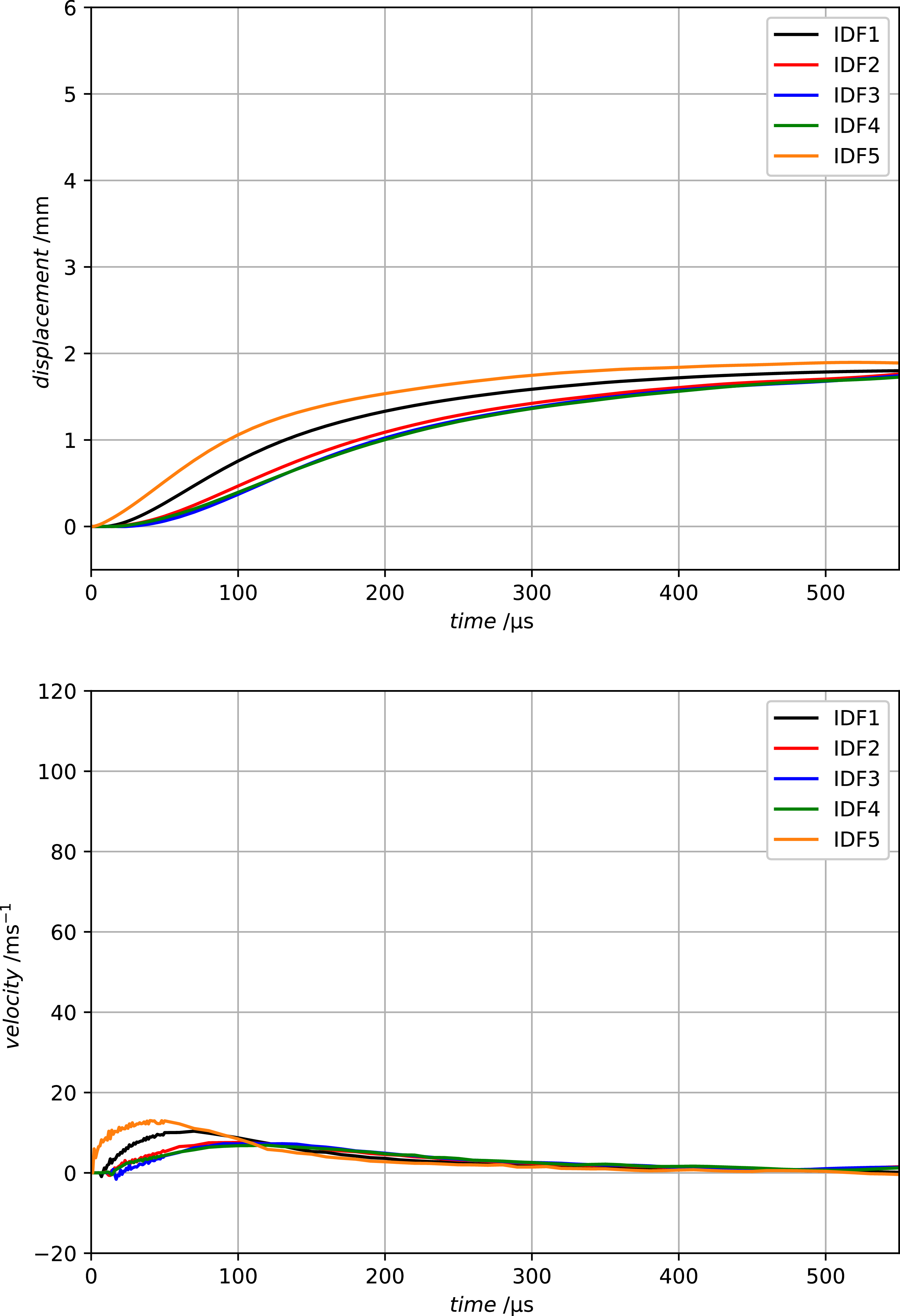
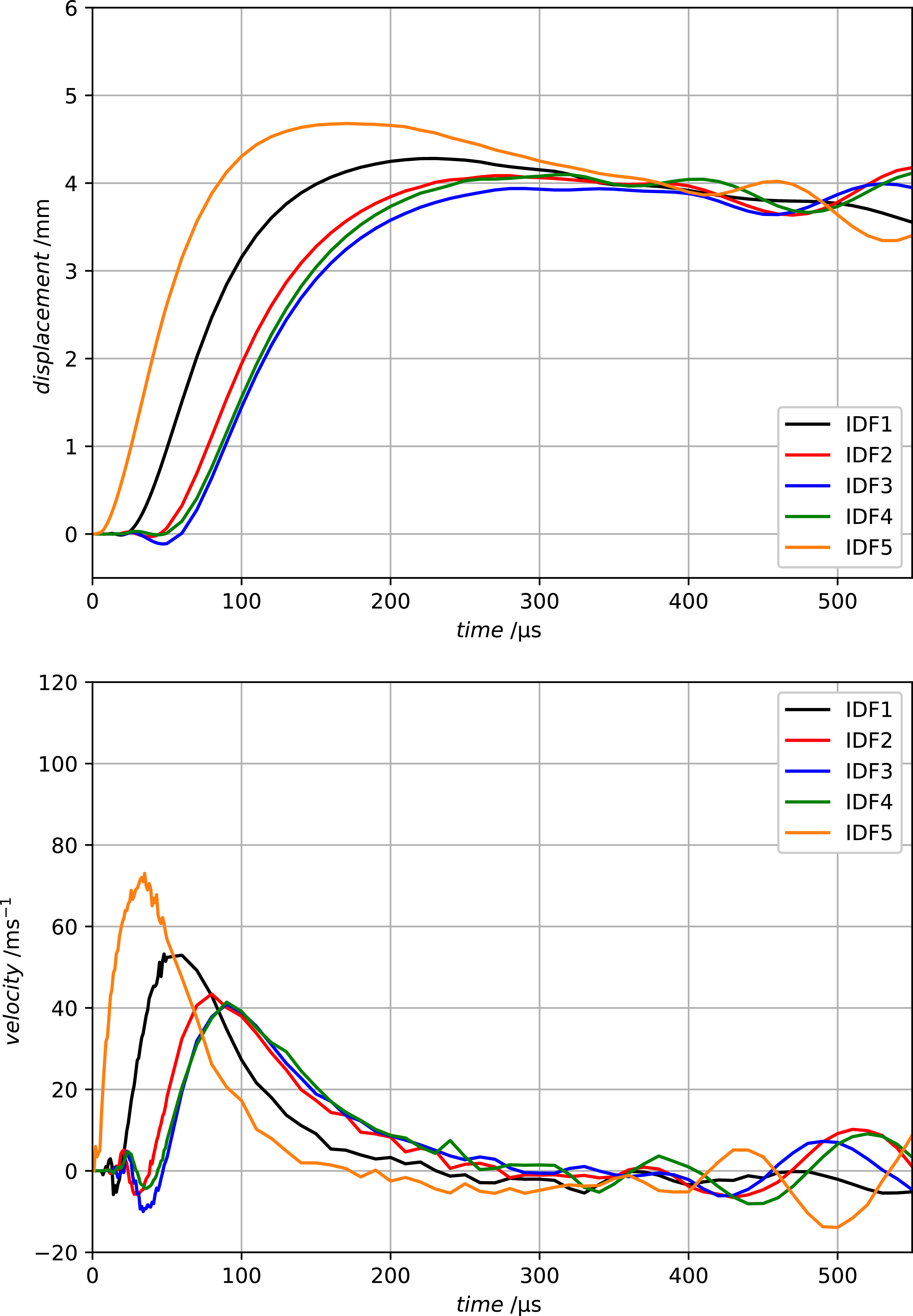
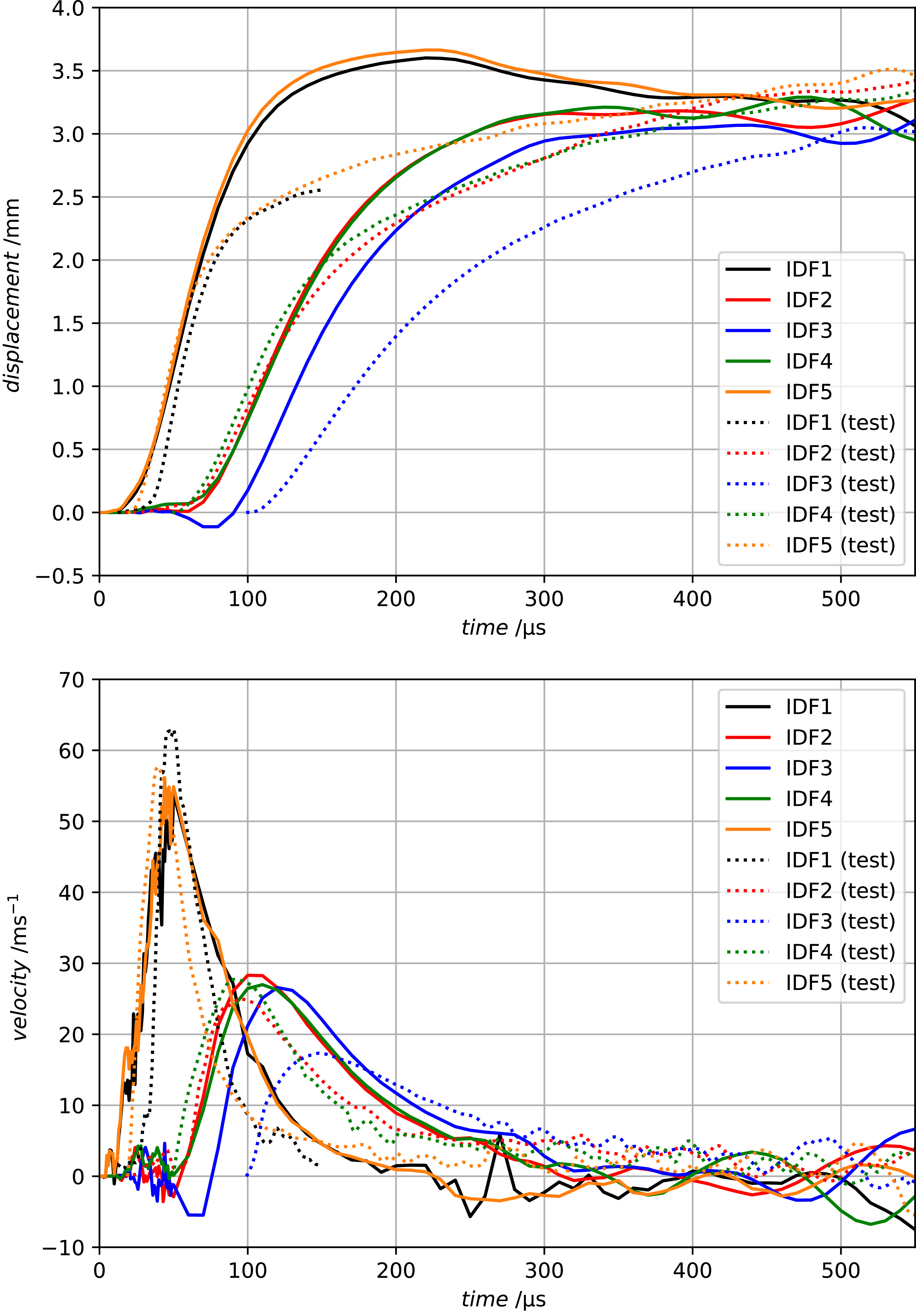
Figures 6–9 show the predicted displacement and velocity histories on the five points identified in Fig. 2 for the unpainted and painted cases with different paint thicknesses. For 300 ${\rm{\mu }}$
m paint thickness, the predictions are compared with the VISAR experimental measurements performed by Lepetit et al. [Reference Lepetit, Escure, Guinard, Revel, Peres and Duval5]; the displacement and velocity histories correlate well between simulations and experiments, validating the hypothesis that the paint layer does not need to be explicitly modelled in the mechanical finite element analysis. It is also clear that the presence of paint, and consequent enhancement of the contribution of the near-surface explosion of the LSP layer, leads to a significantly higher maximum displacement and velocity for the painted cases when compared with the unpainted case. Moreover, as the paint thickness increases, the maximum displacement and velocity also increases, demonstrating that implicitly accounting for the paint layer in the formulation of the mechanical lightning loads allows capturing the trends observed in experiments [Reference Bigand and Duval2, Reference Murillo, Flourens, Garcia, Duval and Cavaliere7].
${\rm{\mu }}$
m paint thickness, the predictions are compared with the VISAR experimental measurements performed by Lepetit et al. [Reference Lepetit, Escure, Guinard, Revel, Peres and Duval5]; the displacement and velocity histories correlate well between simulations and experiments, validating the hypothesis that the paint layer does not need to be explicitly modelled in the mechanical finite element analysis. It is also clear that the presence of paint, and consequent enhancement of the contribution of the near-surface explosion of the LSP layer, leads to a significantly higher maximum displacement and velocity for the painted cases when compared with the unpainted case. Moreover, as the paint thickness increases, the maximum displacement and velocity also increases, demonstrating that implicitly accounting for the paint layer in the formulation of the mechanical lightning loads allows capturing the trends observed in experiments [Reference Bigand and Duval2, Reference Murillo, Flourens, Garcia, Duval and Cavaliere7].
Finite element predictions of the displacement and velocity histories on the five points identified in Fig. 2 for the unpainted case of ECF 73.

Finite element predictions of the displacement and velocity histories on the five points identified in Fig. 2 for a paint thickness of 200 ${\rm{\mu }}$
m and ECF 73.
${\rm{\mu }}$
m and ECF 73.

Finite element predictions of the displacement and velocity histories on the five points identified in Fig. 2 for a paint thickness of 300 ${\rm{\mu }}$
m and ECF 73, and comparison with VISAR experimental measurements [Reference Lepetit, Escure, Guinard, Revel, Peres and Duval5].
${\rm{\mu }}$
m and ECF 73, and comparison with VISAR experimental measurements [Reference Lepetit, Escure, Guinard, Revel, Peres and Duval5].

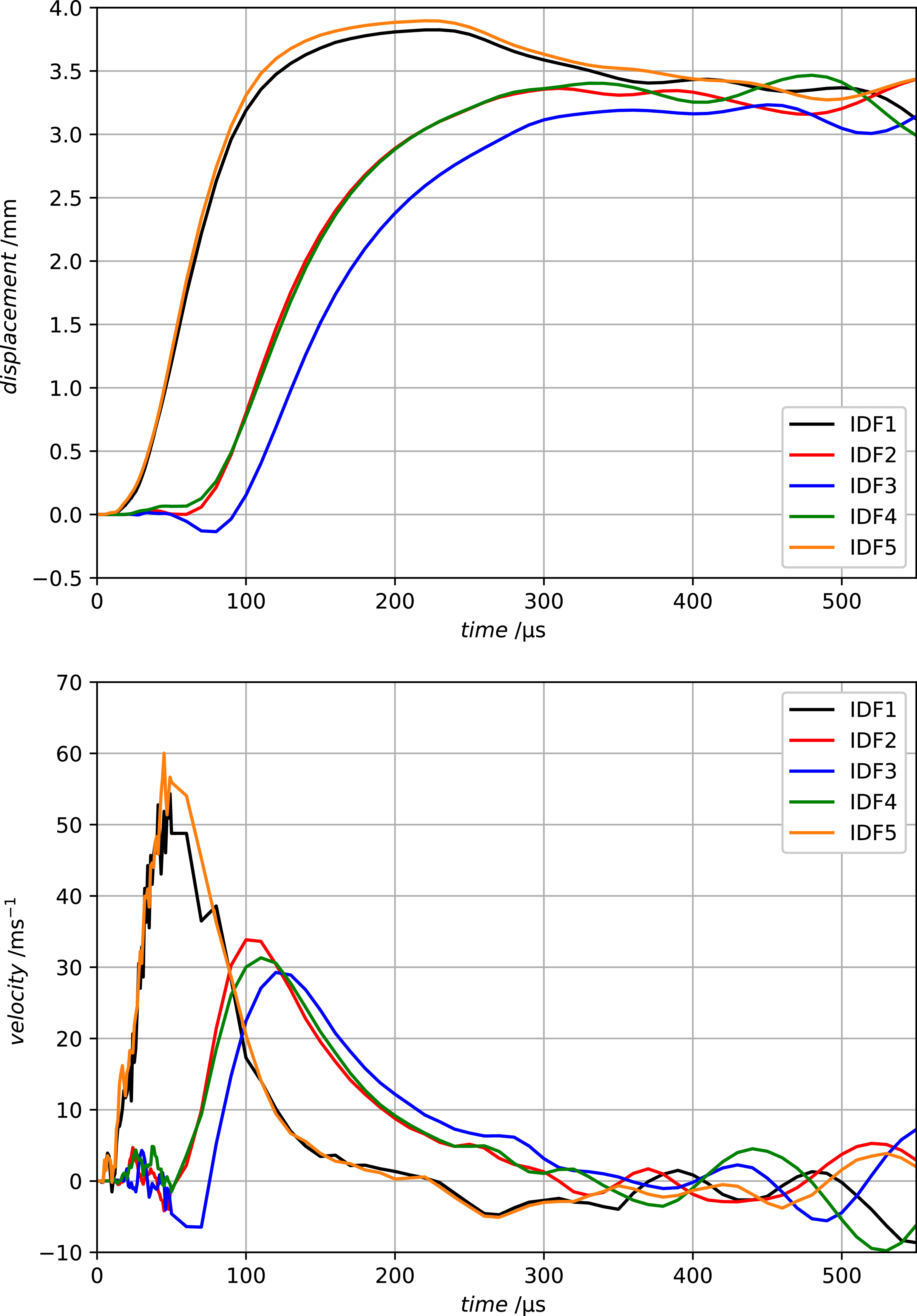
Finite element predictions of the displacement and velocity histories on the five points identified in Fig. 2 for a paint thickness of 400 ${\rm{\mu }}$
m and ECF 73.
${\rm{\mu }}$
m and ECF 73.

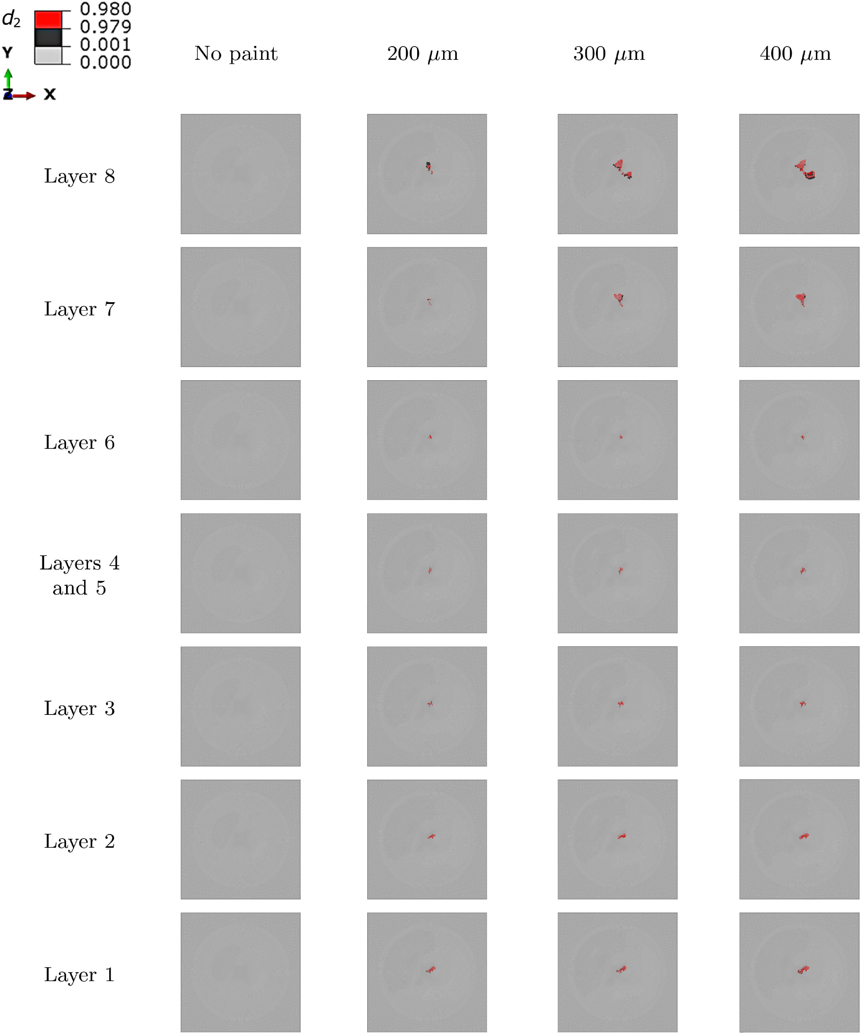
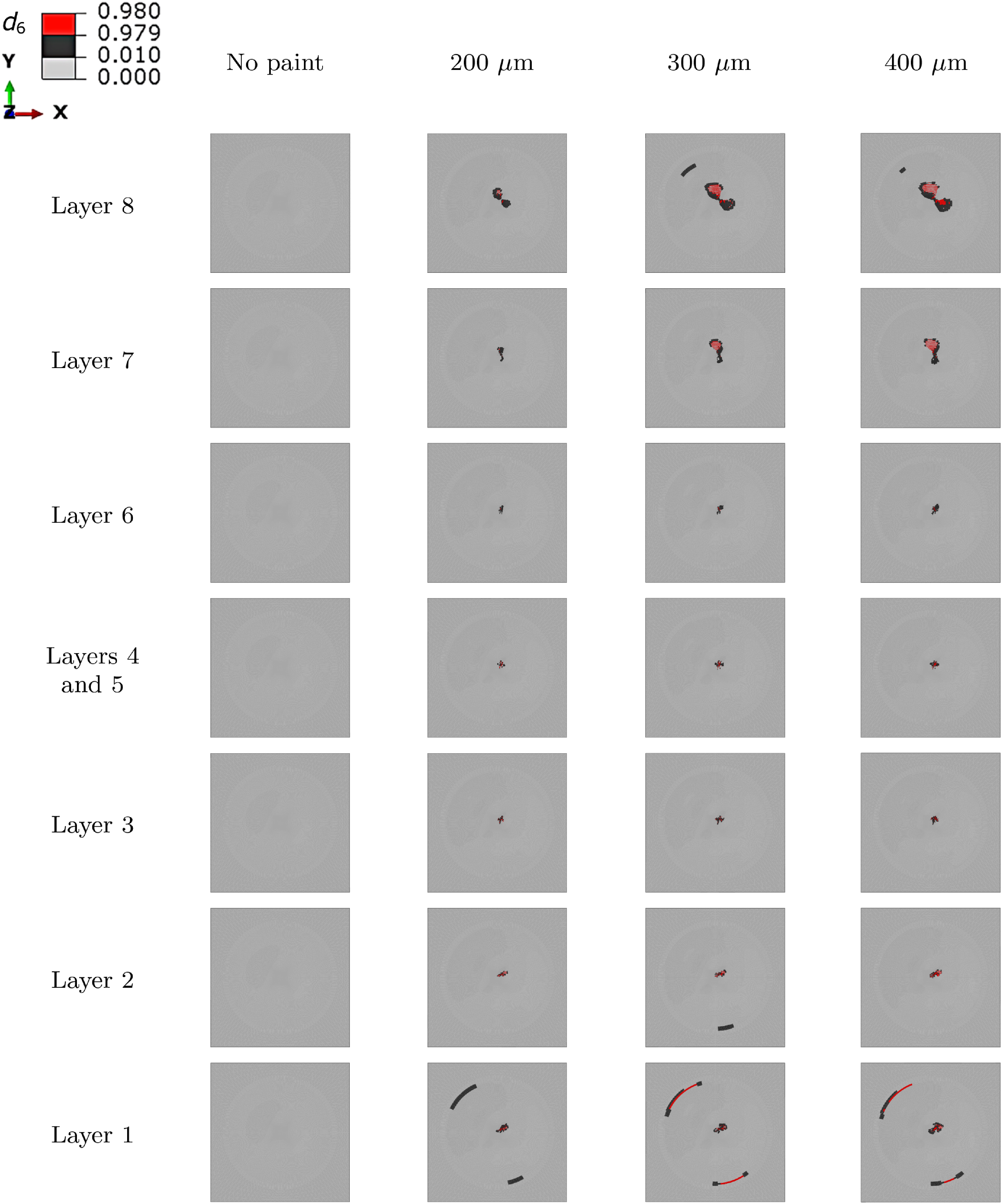
Figures 10–13 show, respectively, the predictions of longitudinal, transverse, shear and interlaminar damage on ECF 73 for the unpainted case and for different paint thicknesses. No damage is observed in the unpainted panels, while an increasing extent of intralaminar and interlaminar damage with increasing paint thickness is observed in the panels coated with a paint layer.
Longitudinal damage ( ${d_1}$
) extent considering the effect of paint thickness for ECF 73. The 0° direction is parallel to the (horizontal) X-axis. The layer count starts from the bottom of the laminate (Layer 1) to the top of the laminate (Layer 8). The latter is immediately below the LSP layer, where the VDLOAD pressure profiles are applied.
${d_1}$
) extent considering the effect of paint thickness for ECF 73. The 0° direction is parallel to the (horizontal) X-axis. The layer count starts from the bottom of the laminate (Layer 1) to the top of the laminate (Layer 8). The latter is immediately below the LSP layer, where the VDLOAD pressure profiles are applied.

Transverse damage ( ${d_2}$
) extent considering the effect of paint thickness for ECF 73. The 0° direction is parallel to the (horizontal) X-axis. The layer count starts from the bottom of the laminate (Layer 1) to the top of the laminate (Layer 8). The latter is immediately below the LSP layer, where the VDLOAD pressure profiles are applied.
${d_2}$
) extent considering the effect of paint thickness for ECF 73. The 0° direction is parallel to the (horizontal) X-axis. The layer count starts from the bottom of the laminate (Layer 1) to the top of the laminate (Layer 8). The latter is immediately below the LSP layer, where the VDLOAD pressure profiles are applied.

Shear damage ( ${d_6}$
) extent considering the effect of paint thickness for ECF 73. The 0° direction is parallel to the (horizontal) X-axis. The layer count starts from the bottom of the laminate (Layer 1) to the top of the laminate (Layer 8). The latter is immediately below the LSP layer, where the VDLOAD pressure profiles are applied.
${d_6}$
) extent considering the effect of paint thickness for ECF 73. The 0° direction is parallel to the (horizontal) X-axis. The layer count starts from the bottom of the laminate (Layer 1) to the top of the laminate (Layer 8). The latter is immediately below the LSP layer, where the VDLOAD pressure profiles are applied.

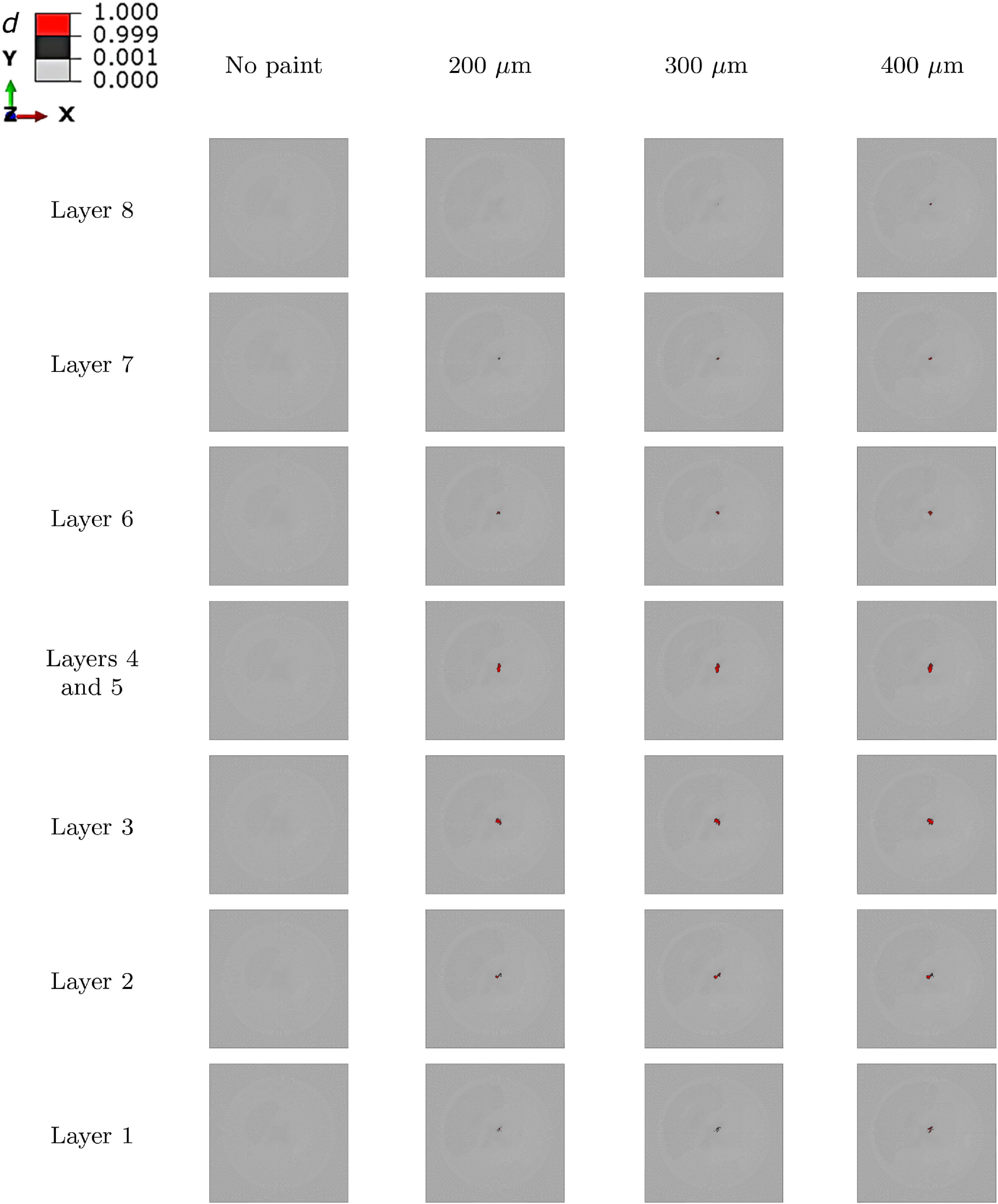
Interlaminar damage ( $d$
) extent considering the effect of paint thickness for ECF 73. The 0° direction is parallel to the (horizontal) X-axis. The layer count starts from the bottom of the laminate (Layer 1) to the top of the laminate (Layer 8). The latter is immediately below the LSP layer, where the VDLOAD pressure profiles are applied.
$d$
) extent considering the effect of paint thickness for ECF 73. The 0° direction is parallel to the (horizontal) X-axis. The layer count starts from the bottom of the laminate (Layer 1) to the top of the laminate (Layer 8). The latter is immediately below the LSP layer, where the VDLOAD pressure profiles are applied.

6.2 ECF 195 LSP layer
Following the study of ECF 73, Figs 14–17 now show the numerical results obtained for ECF 195. Again, the predictions for 300 ${\rm{\mu }}$
m paint thickness are compared with the VISAR experimental measurements performed by Lepetit et al. [Reference Lepetit, Escure, Guinard, Revel, Peres and Duval5], whose good correlation reinforces the hypothesis that the paint layer does not need to be explicitly modelled in the mechanical finite element analysis. Also here, the presence of paint, and consequent enhancement of the contribution of the near-surface explosion of the LSP layer, leads to an increase of the displacement and velocity amplitudes, which keep increasing as the thickness of the paint layer increased from 200 to 400
${\rm{\mu }}$
m paint thickness are compared with the VISAR experimental measurements performed by Lepetit et al. [Reference Lepetit, Escure, Guinard, Revel, Peres and Duval5], whose good correlation reinforces the hypothesis that the paint layer does not need to be explicitly modelled in the mechanical finite element analysis. Also here, the presence of paint, and consequent enhancement of the contribution of the near-surface explosion of the LSP layer, leads to an increase of the displacement and velocity amplitudes, which keep increasing as the thickness of the paint layer increased from 200 to 400 ${\rm{\mu }}$
m. This again demonstrates, now for a higher electrically conducting LSP layer, that implicitly accounting for the paint layer in the formulation of the mechanical lightning loads allows capturing the trends observed in experiments [Reference Bigand and Duval2, Reference Murillo, Flourens, Garcia, Duval and Cavaliere7].
${\rm{\mu }}$
m. This again demonstrates, now for a higher electrically conducting LSP layer, that implicitly accounting for the paint layer in the formulation of the mechanical lightning loads allows capturing the trends observed in experiments [Reference Bigand and Duval2, Reference Murillo, Flourens, Garcia, Duval and Cavaliere7].
Finite element predictions of the displacement and velocity histories on the five points identified in Fig. 2 for the unpainted case of ECF 195.

Finite element predictions of the displacement and velocity histories on the five points identified in Fig. 2 for a paint thickness of 200 ${\rm{\mu }}$
m and ECF 195.
${\rm{\mu }}$
m and ECF 195.

Finite element predictions of the displacement and velocity histories on the five points identified in Fig. 2 for a paint thickness of 300 ${\rm{\mu }}$
m and ECF 195, and comparison with VISAR experimental measurements [Reference Lepetit, Escure, Guinard, Revel, Peres and Duval5].
${\rm{\mu }}$
m and ECF 195, and comparison with VISAR experimental measurements [Reference Lepetit, Escure, Guinard, Revel, Peres and Duval5].

Finite element predictions of the displacement and velocity histories on the five points identified in Fig. 2 for a paint thickness of 400 ${\rm{\mu }}$
m and ECF 195.
${\rm{\mu }}$
m and ECF 195.

Figures 18–21 show, respectively, the predictions of longitudinal, transverse, shear and interlaminar damage on ECF 195. As in ECF 73 (Figs 8–11), no damage is observed in the unpainted panels, while an increasing extent of intralaminar and interlaminar damage with increasing paint thickness is observed in the panels with paint.
Longitudinal damage ( ${d_1}$
) extent considering the effect of paint thickness for ECF 195. The 0° direction is parallel to the (horizontal) X-axis. The layer count starts from the bottom of the laminate (Layer 1) to the top of the laminate (Layer 8). The latter is immediately below the LSP layer, where the VDLOAD pressure profiles are applied.
${d_1}$
) extent considering the effect of paint thickness for ECF 195. The 0° direction is parallel to the (horizontal) X-axis. The layer count starts from the bottom of the laminate (Layer 1) to the top of the laminate (Layer 8). The latter is immediately below the LSP layer, where the VDLOAD pressure profiles are applied.

Transverse damage ( ${d_2}$
) extent considering the effect of paint thickness for ECF 195. The 0° direction is parallel to the (horizontal) X-axis. The layer count starts from the bottom of the laminate (Layer 1) to the top of the laminate (Layer 8). The latter is immediately below the LSP layer, where the VDLOAD pressure profiles are applied.
${d_2}$
) extent considering the effect of paint thickness for ECF 195. The 0° direction is parallel to the (horizontal) X-axis. The layer count starts from the bottom of the laminate (Layer 1) to the top of the laminate (Layer 8). The latter is immediately below the LSP layer, where the VDLOAD pressure profiles are applied.

Shear damage ( ${d_6}$
) extent considering the effect of paint thickness for ECF 195. The 0° direction is parallel to the (horizontal) X-axis. The layer count starts from the bottom of the laminate (Layer 1) to the top of the laminate (Layer 8). The latter is immediately below the LSP layer, where the VDLOAD pressure profiles are applied.
${d_6}$
) extent considering the effect of paint thickness for ECF 195. The 0° direction is parallel to the (horizontal) X-axis. The layer count starts from the bottom of the laminate (Layer 1) to the top of the laminate (Layer 8). The latter is immediately below the LSP layer, where the VDLOAD pressure profiles are applied.

Interlaminar damage ( $d$
) extent considering the effect of paint thickness for ECF 195. The 0° direction is parallel to the (horizontal) X-axis. The layer count starts from the bottom of the laminate (Layer 1) to the top of the laminate (Layer 8). The latter is immediately below the LSP layer, where the VDLOAD pressure profiles are applied.
$d$
) extent considering the effect of paint thickness for ECF 195. The 0° direction is parallel to the (horizontal) X-axis. The layer count starts from the bottom of the laminate (Layer 1) to the top of the laminate (Layer 8). The latter is immediately below the LSP layer, where the VDLOAD pressure profiles are applied.

7.0 Discussion
Because the model of the overpressure generated by the explosion of the LSP layer can account for the effect of paint thickness, the related mechanical loads allow predicting paint thickness effects on the mechanical response and damage of protected CFRP laminates. In this study, the predictions show that the deflection for a 400 ${\rm{\mu }}$
m paint layer is about 3
${\rm{\mu }}$
m paint layer is about 3 $ \times $
higher than the unpainted case for ECF 73, and 2.2
$ \times $
higher than the unpainted case for ECF 73, and 2.2 $ \times $
higher for ECF 195. Moreover, the velocity histories demonstrate that thicker paint layers lead to faster deflection of the panel, as observed in literature [Reference Murillo, Flourens, Garcia, Duval and Cavaliere7].
$ \times $
higher for ECF 195. Moreover, the velocity histories demonstrate that thicker paint layers lead to faster deflection of the panel, as observed in literature [Reference Murillo, Flourens, Garcia, Duval and Cavaliere7].
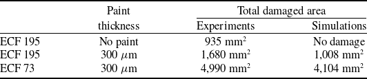
Experimental data available for the laminates with a 300 ${\rm{\mu }}$
m paint layer show that the proposed models can capture the displacement and velocity fields [Reference Karch, Arteiro and Camanho25] reasonably well (see Figs 8 and 16), as well as the total delaminated area identified by C-scan below the second plyFootnote
1
(Table 8) when considering the predicted combined extent of matrix-dominated damage (
${\rm{\mu }}$
m paint layer show that the proposed models can capture the displacement and velocity fields [Reference Karch, Arteiro and Camanho25] reasonably well (see Figs 8 and 16), as well as the total delaminated area identified by C-scan below the second plyFootnote
1
(Table 8) when considering the predicted combined extent of matrix-dominated damage ( ${d_i},{\rm{\;\;}}i = 2,6$
, and
${d_i},{\rm{\;\;}}i = 2,6$
, and $d$
).
$d$
).
C-scan data of the experiments reported by Lepetit et al. [Reference Lepetit, Escure, Guinard, Revel, Peres and Duval5], available for unpainted ECF 195, ECF 195 with 300 ${\rm{\mu }}$
m equivalent paint layer thickness and ECF 73 with 300
${\rm{\mu }}$
m equivalent paint layer thickness and ECF 73 with 300 ${\rm{\mu }}$
m equivalent paint layer thickness, and comparison with the sum of delaminated areas for all interfaces below the second ply obtained from the simulations of this study
${\rm{\mu }}$
m equivalent paint layer thickness, and comparison with the sum of delaminated areas for all interfaces below the second ply obtained from the simulations of this study

Lepetit et al. [Reference Lepetit, Escure, Guinard, Revel, Peres and Duval5] also show velocity measurements at the VISAR point closer to the initial lightning strike attachment (corresponding to IDF5, see Fig. 2) of an unpainted panel with ECF 195, with a peak velocity of approximately 10 m/s, matched by the predictions in Fig. 14. However, C-scan data (Table 8) show damage occurring on the unpainted panel with ECF 195, which is not predicted by the models (see Figs 18–21). In fact, the results of this study show an under-prediction of damage extent for all configurations with C-scan data available (Table 8). Hence, although the predictions of the effect of paint thickness are consistent with the available data [Reference Lepetit, Escure, Guinard, Revel, Peres and Duval5] and literature [Reference Bigand and Duval2, Reference Murillo, Flourens, Garcia, Duval and Cavaliere7] by predicting a clear increase of damage extent in the protected CFRP laminates with increasing paint thickness (Figs 10–13 and 18–21), there is room for improvement in terms of damage prediction accuracy. One possible explanation for the under-predictions of this study is the fact that all material properties are considered independent of temperature; although the temperature rise in these cases is not expected to cause thermal damage, it may be sufficient to soften the polymer matrix and therefore facilitate damage onset. Yet, it is important to note that the experimentally measured total delaminated area of the ECF 195 unpainted panel is approximately 1.8 $ \times $
smaller than the total delaminated area measured below the second ply of the painted case (with a 300
$ \times $
smaller than the total delaminated area measured below the second ply of the painted case (with a 300 ${\rm{\mu }}$
m paint layer).
${\rm{\mu }}$
m paint layer).
8.0 Concluding remarks
The models proposed in this work predict the faster deflection and the increase of damage extent with the increase of paint thickness so far observed experimentally [Reference Bigand and Duval2, Reference Lepetit, Escure, Guinard, Revel, Peres and Duval5, Reference Murillo, Flourens, Garcia, Duval and Cavaliere7] without fitting parameters calibrated based on test data for different paint thicknesses. Moreover, they satisfactorily capture the effect of paint thickness for LSP layers of different areal weight, following the experimentally observed trends reported in literature [Reference Bigand and Duval2, Reference Lepetit, Escure, Guinard, Revel, Peres and Duval5, Reference Murillo, Flourens, Garcia, Duval and Cavaliere7]. It is important to mention that the possibility of having a tool that is capable of predicting the effect of paint thickness on the damage induced by lightning strikes could support the assessment of the thickness of the paint layer that minimises mechanical damage induced by lightning strikes, at the same time it complies with the environmental protection requirements. Improvements to the models presented in this study include the addition of strain-rate and temperature dependency in the constitutive models, which are expected to increase the level of fidelity of these simulations. Moreover, building upon the development and validation of appropriate models for the thermal, thermal-mechanical and mechanical lightning loads (the latter being addressed in the present work) and for the composite material behaviour could ultimately support the qualification and certification by analysis of new LSP technologies [Reference Kumar, Yokozeki, Karch, Hassen, Hershey, Kim, Lindahl, Barnes, Bandari and Kunc8] and of protected (generally painted) composite aero-structures subjected to lightning strike.
Acknowledgements
The authors acknowledge the financial support provided by AIRBUS, under the contracts ‘Modelling and Simulation of Lightning Induced Damage of Composite Structures’, ‘Improved simulation of mechanical lightning loads on composite laminated structures’, ‘Lightning Protection’, ‘Lightning Induced Damage of Composite Structures’ and ‘Damage Mechanics for Lightning Strike of Protected CFRP Structures’. A. Arteiro acknowledges Fundação para a Ciência e a Tecnologia (FCT) for its financial support to LAETA via the project UID/50022/2025 (https://doi.org/10.54499/UID/50022/2025).
Competing interests
The authors declare none.


 Open access