1. INTRODUCTION
Satellite formation flying is one of the typical forms of a so-called Distributed Space System, in which more than two spacecraft are flying in a coordinated manner to fulfil a particular space mission. The formation flying of spacecraft to replace a single large satellite will provide opportunities for a number of future applications, including synthetic apertures for high-resolution interferometry missions. Such missions require precise relative satellite state (position and velocity) information. Hence relative navigation is one of the primary tasks in a satellite formation flying mission.
Traditionally external observations from ground stations have been used for satellite orbit determination. However, more and more space missions benefit from the use of an autonomous navigation system, which can estimate a satellite's state using the measurements available on board. Since the beginning of the 1990s, the U.S. Global Positioning System (GPS) has been used for spacecraft navigation, providing high precision orbit information with minimum ground intervention.
The differential GPS technique can produce sub-centimetre-level relative positioning precision and accuracy in software or/and hardware-in-the-loop simulations, and centimetre-level precision in (near) real time for low Earth orbit (LEO) satellite formation flying missions. One significant issue affecting relative navigation performance is the inter-satellite distance. For formations with large separation, e.g. over 100 km, even though most common GPS errors can be eliminated by using the double-differenced observables, ionospheric delay residuals may still be significant. Moreover, the common-in-view GPS satellites change rapidly, which will degrade the success rates of integer ambiguity resolution and lead to solution gaps when there are insufficient double-differenced observables (Mohiuddin and Psiaki, Reference Mohiuddin and Psiaki2005; Tancredi et al., Reference Tancredi, Renga and Grassi2010; Montenbruck and D'Amico, Reference Montenbruck and D'Amico2013). As a consequence, the navigation performance will deteriorate significantly. Relative positioning performance for some formation flying missions are summarised in Table 1.
Relative positioning performance using real data for several LEO formation flying missions.

Given the wide range of formation flying missions, a single navigation system will not necessarily be able to meet all functional and operational requirements. For example, as introduced in the previous section, some weakness still exists in GPS standalone baseline determination for satellite formation flying applications. However, inter-satellite ranging observations are sometimes available for satellite formation flying missions to provide robust and autonomous measurements (Tapley et al., Reference Tapley, Bettadpur, Ries, Thompson and Watkins2004; Montenbruck et al., Reference Montenbruck, Delpech, Ardaens, Delong, D'Amico and Harr2008). Inter-satellite ranging systems are categorised as optical, radio, laser, or laser interferometry (Renga et al., Reference Renga, Grassi and Tancredi2013). Radio signal measurement is the most mature class of technology.
The Gravity Recovery and Climate Experiment (GRACE) mission has successfully demonstrated the use of inter-satellite ranging between two satellites to aid determination of the Earth's gravitational field in a precise manner (Tapley et al., Reference Tapley, Bettadpur, Ries, Thompson and Watkins2004). The relative distance between the satellites is measured with a resolution of 10 μm using a K/Ka-band ranging (KBR) system, which is a dual one-way ranging instrument. A GRACE follow-on mission is planned to launch in 2017 (Sheard et al., Reference Sheard, Heinzel, Danzmann, Shaddock, Klipstein and Folkner2012). It is planned to use microwave ranging as the primary instrument for inter-satellite distance measurements, however laser interferometry has been proposed as an alternative system, able to achieve improved inter-satellite ranging precision. Another mission known as PRISMA also benefits from use of a radio frequency (RF) metrology subsystem for relative positioning (Montenbruck et al., Reference Montenbruck, Delpech, Ardaens, Delong, D'Amico and Harr2008). A summary of these systems is given in Table 2.
Inter-satellite ranging systems for some LEO formation flying missions.

In these flight missions the inter-satellite ranging instruments have been applied to measure the inter-satellite baseline directly, or with the aid of GPS. An augmented relative navigation system (ARNS) is one that combines GPS measurements with inter-satellite range measurements, which is able to provide a sufficient number of measurements, as well as more rapid and stable navigation filter solutions. In this navigation system, the inter-satellite range measurement is treated as a new observation, which can be combined with the original GPS stand-alone measurements. Alternatively, the baseline measurement can be used as a non-linear equality constraint. A number of approaches to applying equality constraints with a Kalman filter framework (Simon, Reference Simon2010) can also be applied to the ARNS. In particular, a smoothly-constrained Kalman filter (SCKF) (De Geeter et al., Reference De Geeter, Van Brussel, De Schutter and Decreton1997) can be used.
An augmented relative navigation system for satellite formation flying is described in this paper. Section 2 presents the functional models and the extended Kalman filter architecture for the stand-alone GPS-based kinematic relative navigation system. Section 3 introduces two approaches to incorporating the extra measurements from the inter-satellite ranging instrument into the ARNS. A phase ambiguity fixing and feedback scheme is investigated in Section 4. A set of fight data from the GRACE mission was used to test and validate the ARNS performance.
2. GPS-BASED KINEMATIC RELATIVE NAVIGATION
The double-differenced GPS observables are widely used to obtain high accuracy baseline solutions. By taking differences between GPS satellites and two receivers the double-differenced observation equation can be written as follows:
 $$\eqalign{ & \delta PR_{r_{cd}} ^{s_{ij, f}} = - {\bf los}_{r_d, 0}^{s_{ij}} \delta {\bi r}_{r_{cd}} - \dot \rho _{r_c} ^{s_i} \delta cl_{r_c} + \dot \rho _{r_c} ^{s_j} \delta cl_{r_c} + \dot \rho _{r_d} ^{s_i} \delta cl_{r_d} - \dot \rho _{r_d} ^{s_j} \delta cl_{r_d} + I_{r_{cd}} ^{s_{ij, f}} + \nu _{r_{cd}} ^{s_{ij, f}} \cr & \delta CP_{r_{cd}} ^{s_{ij, f}} = - {\bf los}_{r_d, 0}^{sij} \delta {\bi r}_{r_{cd}} - \dot \rho _{r_c} ^{s_i} \delta cl_{r_c} + \dot \rho _{r_c} ^{s_j} \delta cl_{r_c} + \dot \rho _{r_d} ^{s_i} \delta cl_{r_d} - \dot \rho _{r_d} ^{s_j} \delta cl_{r_d} - I_{r_{cd}} ^{s_{ij, f}} + \lambda ^f N_{r_{cd}} ^{s_{ij, f}} + \nu _{r_{cd}} ^{s_{ij}}} $
where the superscript s and f indicate the GPS satellite and the signal frequency respectively, and subscript r indicates the receiver. The terms in the equations are:
δ Increment operator: $\delta \left( {} \right) = \left( {} \right) - \left( {} \right)_0 $
PR, CP Code phase and carrier phase observations [m]
ρ PR, ρCP Geometric distance between receiver and GPS satellites [m]
I Ionospheric delay [m]
cl Clock error [s]
λf Signal wavelength at frequency f [m]
N Carrier phase integer ambiguity [cycle]
v Unmodelled code phase and carrier phase errors [m]

As indicated in the above models, the terms associated with the receiver clock errors remain and need to be accounted for. A typical GPS receiver with a pulse per second output can provide an accuracy of between 100 nanoseconds and 1 microsecond. In the high dynamic motion of a spacecraft where the multiplier $\dot \rho _r^s $ is large, e.g. about 7·5 km/s on a 500 km circular orbit, the magnitude of these terms will be at the millimetre level and can be ignored. Common expressions of the double-differenced models are the same as those used in terrestrial scenarios:
 $$\eqalign{& \delta PR_{r_{cd}} ^{s_{ij}, f} = - {\bf los}_{r_d, 0}^{s_{ij}} \delta {\bi r}_{r_{cd}} + I_{r_{cd}} ^{s_{ij}, f} + \nu _{r_{cd}} ^{s_{ij}, f} \cr & \delta CP_{r_{cd}} ^{s_{ij}, f} = - {\bf los}_{r_d, 0}^{sij} \delta {\bi r}_{r_{cd}} - I_{r_{cd}} ^{s_{ij}, f} + \lambda ^f N_{r_{cd}} ^{s_{ij}, f} + \nu _{r_{cd}} ^{s_{ij}}} $$
The extended Kalman filter (EKF) can be used to resolve the optimal estimation problem of non-linear systems, which are linearized around the current estimate and its covariance. The relative navigation system employs a common EKF for estimating the relative states of two spacecraft. The single point positioning (SPP) approach is used to estimate the absolute orbits and receiver clock errors, which are then treated as the initial approximate values for linearization of the system of equations. A several metre-level of accuracy for absolute orbit determination is sufficient. The unknown parameters to be estimated are:
 $$x = (r_{xc}, r_{yc}, r_{zc}, cl_c, r_{xd}, r_{yd}, r_{zd}, cl_d, {\bf B},vTEC_c, vT\dot EC_c, vTEC_d, vT\dot EC_d, {\bf N})^T $
The subscript c and d designate the “chief” and “deputy” spacecraft, respectively, [r x, ry, rz] are the absolute position components in the Earth-Centred-Earth-Fixed (ECEF) coordinate system, cl denotes the receiver clock error, B=[B x, By, Bz] is the baseline vector, vTEC and $vT\dot EC$ are the vertical total electron content and its rate, respectively. ${\bf N} = (N_{cd}^{1,L_1}, N_{cd}^{2,L_1}, \cdots N_{cd}^{i,L_1}, N_{cd}^{1,L_2}, N_{cd}^{2,L_2}, \cdots N_{cd}^{i,L_2} )^T $ denotes the single-differenced carrier phase ambiguities. Only $({\bf B},vTEC_c, vT\dot EC_c, vTEC_d, vT\dot EC_d, {\bf N})^T $ are estimated as states in the EKF. The formulation of the first order ionospheric error with respect to vTEC can be expressed as:
 $$I_r^s = \displaystyle{{40{\cdot}3} \over {\,f^2}} \cdot m \cdot vTEC$$
where m is the mapping function and f denotes the carrier frequency. Since GPS observations by space borne receivers are all measured within the ionosphere rather than underneath it, the ionospheric pierce point model used for terrestrial receivers cannot be applied directly. The Lear mapping function (Leung and Montenbruck, Reference Leung and Montenbruck2005; van Barneveld et al., Reference van Barneveld, Montenbruck and Visser2008) is commonly used, which is dependent on the elevation angle:
 $$m\left( E \right) = \displaystyle{{2{\cdot}037} \over {\sqrt {\sin ^2 E + 0{\cdot}076} + \sin E}}$$
There are two steps in the EKF process: state prediction and state propagation. When only the kinematic relative navigation approach is applied, the baseline components can be propagated using the identify matrix without any a priori knowledge of relative motion. vTEC is modelled to change with a constant rate within a short time interval. Based on this assumption, its dynamics can be modelled as a second-order random walk process. In the state prediction step the relative states propagate as follows:
 $$\eqalign{ & {\bf \hat B}_{k + 1}^ - = {\bf \hat B}_k^ + \cr & vT\hat EC_{c,k + 1}^ - = vT\hat EC_{c,k}^ + + vT\hat{ \dot E}C_{c,k}^ + \cdot (t_{k + 1} - t_k ) \cr & vT\hat EC_{d,k + 1}^ - = vT\hat EC_{d,k}^ + + vT\hat {\dot E}C_{d,k}^ + \cdot (t_{k + 1} - t_k ) \cr & (vT\hat {\dot E}C_c, vT\hat {\dot E}C_d, {\bf N})_{k + 1}^ - = (vT\hat {\dot E}C_c, vT\hat {\dot E}C_d, {\bf N})_k^ +} $$
After the ionosphere error is modelled with respect to vTEC by means of the Lear mapping function, the double-differenced observables can be finally expressed as:
 $$\eqalign{ & \delta PR_{r_{cd}} ^{s_{ij}, L_1} = - {\bf los}_{r_d, 0}^{s_{ij}} {\bf B} + \displaystyle{1 \over {\,f_{L_1} ^2}} (m_d^{ij} vTEC_d - m_c^{ij} vTEC_c ) + \nu _{PR_{cd}} ^{s_{ij}, L_1} \cr & \delta PR_{r_{cd}} ^{s_{ij}, L_2} = - {\bf los}_{r_d, 0}^{s_{ij}} {\bf B} + \displaystyle{1 \over {\,f_{L_2} ^2}} (m_d^{ij} vTEC_d - m_c^{ij} vTEC_c ) + \nu _{PR_{cd}} ^{s_{ij}, L_2} \cr & \delta CP_{r_{cd}} ^{s_{ij}, L_1} = - {\bf los}_{r_d, 0}^{sij} {\bf B} - \displaystyle{1 \over {\,f_{L_1} ^2}} (m_d^{ij} vTEC_d - m_c^{ij} vTEC_c ) + \lambda ^f (N_{r_{cd}} ^{s_i, L_1} - N_{r_{cd}} ^{s_j, L_1} ) + \nu _{CP_{cd}} ^{s_{ij}, L_1} \cr & \delta CP_{r_{cd}} ^{s_{ij}, L_2} = - {\bf los}_{r_d, 0}^{sij} {\bf B} - \displaystyle{1 \over {\,f_{L_2} ^2}} (m_d^{ij} vTEC_d - m_c^{ij} vTEC_c ) + \lambda ^f (N_{r_{cd}} ^{s_i, L_2} - N_{r_{cd}} ^{s_j, L_2} ) + \nu _{CP_{cd}} ^{s_{ij}, L_2}} $
3. AUGMENTED RELATIVE NAVIGATION SYSTEM
Two approaches can be used to implement the augmented navigation system with baseline measurements: system re-parameterisation and a smoothly-constrained Kalman filter (SCKF).
3.1. System re-parameterisation
RF inter-satellite observations may be range and carrier phase:
 $$\eqalign{& R_{BL} = \rho _{BL} + E_r + \sigma _r \cr & P_{BL} = \rho _{BL} + E_p + b + \sigma _p} $
ρ BL denotes the true range, b denotes the phase ambiguity, and E denotes the total of other errors or biases such as antenna offsets, ionospheric errors and light time delays. As in the case of GPS measurements, the RF measurements are the lower accuracy but unbiased range measurements, and the more accurate but biased carrier phase measurements. If the bias is removed and other errors are corrected, both observations will have a design matrix similar to GPS measurements:
 $$\eqalign{ & C = \displaystyle{{\partial c} \over {\partial x}} = \left( {\displaystyle{{\rho _{BL}} \over {B_x}} \displaystyle{{\rho _{BL}} \over {B_y}} \displaystyle{{\rho _{BL}} \over {B_z}} \; 0_{1 \times 4} \; 0_{1 \times 2n}} \right) \cr & R = \sigma _{BL}^2} $$
where n is the number of common-in-view satellites. The inter-satellite range measurements are combined with GPS measurements in the augmented design matrix:
$$H^* = \left[ \matrix{\matrix{ { - {\bf los}_{r_d, 0}^{s_{12}}} & { - \displaystyle{{m_c^{12}} \over {\,f_{L_1} ^2}}} & 0 & {\displaystyle{{m_d^{12}} \over {\,f_{L_1} ^2}}} & 0 & 0 & \cdots & 0 & 0 & \cdots & 0 \cr \vdots & \vdots & \vdots & \vdots & \vdots & \vdots & \vdots & \vdots & \vdots & \vdots & \vdots \cr { - {\bf los}_{r_d, 0}^{s_{1j}}} & { - \displaystyle{{m_c^{1j}} \over {\,f_{L_1} ^2}}} & 0 & {\displaystyle{{m_d^{1j}} \over {\,f_{L_1} ^2}}} & 0 & 0 & \cdots & 0 & 0 & \cdots & 0 \cr { - {\bf los}_{r_d, 0}^{s_{12}}} & { - \displaystyle{{m_c^{12}} \over {\,f_{L_2} ^2}}} & 0 & {\displaystyle{{m_d^{12}} \over {\,f_{L_2} ^2}}} & 0 & 0 & \cdots & 0 & 0 & \cdots & 0 \cr \vdots & \vdots & \vdots & \vdots & \vdots & \vdots & \vdots & \vdots & \vdots & \vdots & \vdots \cr { - {\bf los}_{r_d, 0}^{s_{1j}}} & { - \displaystyle{{m_c^{1j}} \over {\,f_{L_2} ^2}}} & 0 & {\displaystyle{{m_d^{1j}} \over {\,f_{L_2} ^2}}} & 0 & 0 & \cdots & 0 & 0 & \cdots & 0 \cr { - {\bf los}_{r_d, 0}^{s_{12}}} & {\displaystyle{{m_c^{12}} \over {\,f_{L_1} ^2}}} & 0 & { - \displaystyle{{m_d^{12}} \over {\,f_{L_1} ^2}}} & 0 & 1 & { - 1} & \cdots & 0 & \cdots & 0 \cr \vdots & \vdots & \vdots & \vdots & \vdots & \vdots & \vdots & \vdots & \vdots & \vdots & \vdots \cr { - {\bf los}_{r_d, 0}^{s_{1j}}} & {\displaystyle{{m_d^{1j}} \over {\,f_{L_1} ^2}}} & 0 & { - \displaystyle{{m_d^{1j}} \over {\,f_{L_1} ^2}}} & 0 & 1 & \cdots & { - 1} & 0 & \cdots & 0 \cr { - {\bf los}_{r_d, 0}^{s_{12}}} & {\displaystyle{{m_c^{12}} \over {\,f_{L_2} ^2}}} & 0 & { - \displaystyle{{m_d^{12}} \over {\,f_{L_2} ^2}}} & 0 & 0 & \cdots & 0 & 1 & { - 1} & \cdots \cr \vdots & \vdots & \vdots & \vdots & \vdots & \vdots & \vdots & \vdots & \vdots & \vdots & \vdots \cr { - {\bf los}_{r_d, 0}^{s_{1j}}} & {\displaystyle{{m_c^{1j}} \over {\,f_{L_2} ^2}}} & 0 & { - \displaystyle{{m_d^{1j}} \over {\,f_{L_2} ^2}}} & 0 & 0 & \cdots & 0 & 1 & \cdots & { - 1} \cr} \cr \matrix{ {\displaystyle{{\rho _{BL}} \over {B_x}}} & {\displaystyle{{\rho _{BL}} \over {B_y}}} & {\displaystyle{{\rho _{BL}} \over {B_z}}} & 0 & 0 & 0 & 0 & 0 & \cdots & 0 & 0 & \cdots & 0 \cr} } \right]_{\left( {4n + 1} \right) \times \left( {7 + 2n} \right)} $An iterative EKF strategy can be used to reduce the errors resulting from the nonlinearity of the RF measurements.
3.2. Smoothly-constrained Kalman filter
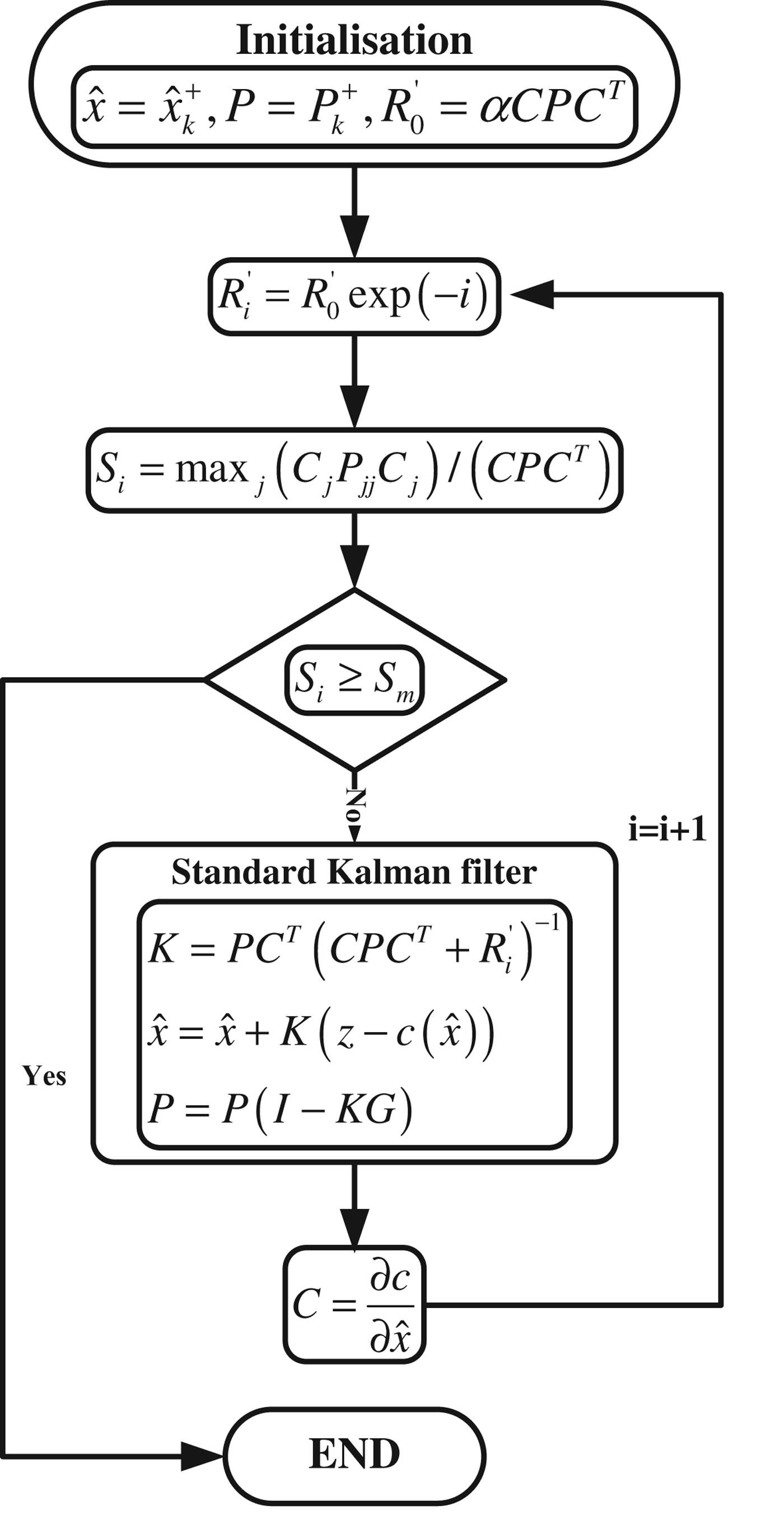
Alternatively, a SCKF can be used to process the inter-satellite measurements. In the derivation of the design matrix, the linearization is applied by truncating the Taylor series to the first order, which will result in two types of error: truncating error and base point error (De Geeter et al., Reference De Geeter, Van Brussel, De Schutter and Decreton1997). In terms of the nonlinearity of the inter-satellite range measurements, a SCKF scheme is also developed in which the ARNS makes the assumption that all the inter-satellite measurements are treated as equality constraints. In addition, the SCKF operates separately from the GPS EKF, as an independent module, which will contribute to a modular design of the relative navigation system. The algorithm is illustrated in Figure 1 (Simon, Reference Simon2010), where α is a tuning parameter and S th is a threshold value, both of which are empirical parameters to control the iterations of the SCKF. c is the constraint equation and C is its Jacobian matrix as expressed in Equation (9).
SCKF algorithm.
4. CARRIER PHASE INTEGER AMBIGUITY FIXING AND FEEDBACK SCHEME
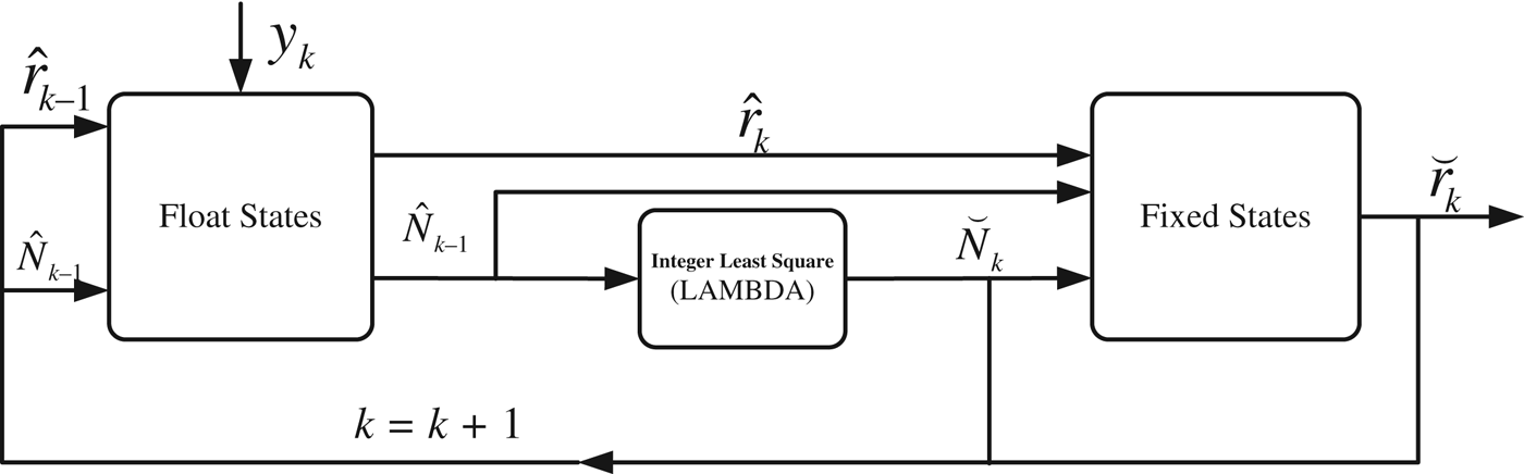
The EKF scheme mentioned in the last section gives the ambiguity float solutions of the relative states. For short baseline scenarios (<10 km), the float solutions have been shown to be of centimetre-level accuracy because the double-differencing operation largely removes the measurements errors (Busse, Reference Busse2003). However, the integer property of the phase ambiguity should be exploited, especially when the residual ionospheric error still contaminates the double-differenced observables in the case of a large separation of the two spacecraft. For applications of satellite navigation/positioning, a more efficient scheme for fixing integer ambiguity is required (Kroes et al., Reference Kroes, Montenbruck, Bertiger and Visser2005; Tancredi et al., Reference Tancredi, Renga and Grassi2013). The ambiguity float solutions obtained from the EKF are used in an integer least squares (ILS) procedure, as implemented by the LAMBDA method. Once the potential integer solutions are verified in the validation step, they are adopted as pseudo-perfect measurements to be introduced into the update of the EKF for the next epoch (shown in Figure 2). A fixed ambiguity is held to an integer value until a cycle slip occurs or the filter diverges with large residuals. The pseudo-perfect measurements are formulated as:
 $$\eqalign{ & z = {\u {\bf N} } \cr & H = \displaystyle{{\partial z} \over {\partial x}} = \left[ {\matrix{ 0 & 0 & 0 & 0 & 0 & 0 & 0 & T \cr}} \right] \cr & R = 0} $$
where T is the transformation matrix between the single-differenced ambiguities and the double-differenced ambiguities, and R is the observation noise matrix which equals zero for a perfect measurement.
Fixed ambiguity feedback scheme for the GPS stand-alone relative navigation system.
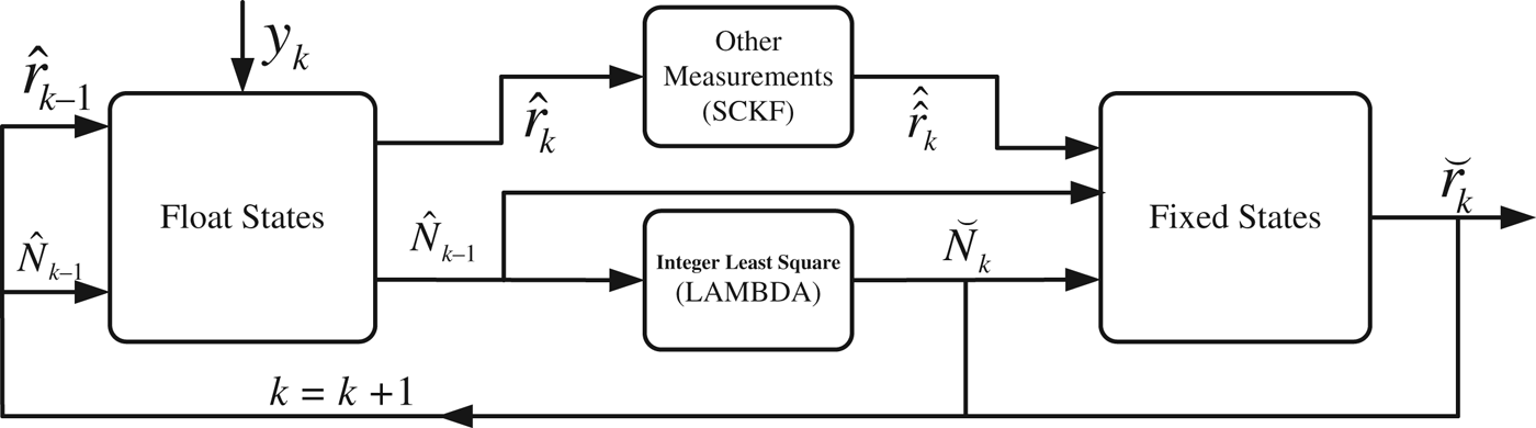
In the ARNS, the procedure for fixing the integer ambiguities is almost the same as in Figure 2. More specifically, when the SCKF is used to deal with the additional range measurements in the ARNS, the float relative states from the EKF are imported into the SCKF first before they are generated as fixed states, and then fed back for the next update of the EKF (Figure 3).
Fixed ambiguity feedback scheme for the SCKF-based ARNS.
5. ARNS PERFORMANCE TESTS USING GRACE FLIGHT DATA
Real data from the GRACE mission was used to test the ARNS performance, as the two identical satellites are equipped with GPS receivers and K/Ka-Band Ranging (KBR) instruments. A post-processed version of the GRACE data, known as Level 1B data, was archived by JPL's Physical Oceanography Distributed Active Archive Centre (PODAAC) and is available to the science community (Case et al., Reference Case, Kruizinga and Wu2002). PODAAC provides GPS flight data and K Band Ranging data products in the format of GPS1B and KBR1B, respectively. The Level 1B data also includes a GPS Navigation (GNV) product that contains precise orbit determination solutions of each spacecraft.
The 24 hour dataset with data interval of ten seconds, from 11 September 2005 has been selected to test the proposed ARNS. There is a gap of 30 minutes for GRACE A observation data due to receiver malfunction from epoch 3509. Hence for relative navigation only 8460 epochs of data are valid. The separation between two satellites ranged from 20 km to 55 km during the day (Figure 4).
Inter-satellite separation for the GRACE mission.
5.1. K/Ka band range measurements
The KBR1B data are the ionosphere-free biased ranges between the GRACE A and B spacecraft. The biased range can be treated as the true range adding an unknown bias that varies at every epoch. A procedure proposed by Kroes (Reference Kroes2006) can be used to extract the true ranges from the biased measurements. After the biases are removed, the inter-satellite range measurements can be taken as additional measurements or treated as tight constraints in the ARNS. As shown in Figure 5, the biased KBR range data is not available for all epochs, and the bias changes with time. In total there are only 6185 epochs of valid unbiased KBR data that can be processed together with double-differenced GPS observables in the ARNS.
Biased KBR data.
5.2. Test results
Several tests have been conducted using the GRACE dataset. The relative positioning results are compared with the GNV products/solutions. The stand-alone GPS measurements are processed to determine the reference trajectory. The baseline estimation errors (expressed in the ECEF frame) are plotted in Figure 6. The 3D RMS error is 0·53 m. When integrating the additional range measurements from the inter-satellite ranging system, the baseline determination accuracy improves significantly, with the 3D RMS error now being at the centimetre-level. In addition, the baseline component errors decrease to the sub-decimetre-level. Figure 7 shows the baseline error components determined using the ARNS with the SCKF algorithm.
Baseline estimation errors for GPS stand-alone solutions.
Baseline estimation errors for SCKF-based ARNS.
However, as the separation distance increases, more peaks in the error occur in all three components. This confirms that long inter-satellite distances will lead to a decrease in the relative navigation performance due to de-correlated ionospheric delays, which will also worsen the phase ambiguity-fixing ratio. Figure 8 shows the vTEC values (in TEC units) for the two GPS receivers, and it can be seen clearly that the vTEC profiles of the two receivers are consistent. However, this consistency reduces as the two spacecrafts' separation increases. In Figure 9 the relative navigation solution modes of all processed epochs are plotted. The carrier phase ambiguity fixed ratio reduces with increasing inter-satellite distance.
VTEC profiles of two spacecraft receivers.
Relative navigation solution modes for the ARNS with fixed ambiguity feedback.
The tests results are summarised in Table 3. The fixed phase integer ambiguity ratio benefits from the feedback strategy, which improves by about 10%, from 71·0% to 81·0%. This strategy also results in an improvement in the relative states estimation. The additional inter-satellite measurements in the ARNS only affect the ambiguity fixing procedure slightly, with less than 1·0% change. However, the ARNS performance has been improved significantly, by one order of baseline magnitude, in comparison with the GPS stand-alone solutions. Both methods – system re-parameterisation and SCKF – can be used to achieve sub-decimetre accuracy of relative state estimation in terms of the distance RMS, and centimetre accuracy for the 3D baseline estimation.
Test results in terms of RMS error and fixed ratio value.

6. CONCLUDING REMARKS
An inter-satellite ranging augmented GPS relative navigation system has been presented in this paper. To combine the inter-satellite measurements with GPS, two approaches were investigated. In the first method, system re-parameterisation, the original GPS stand-alone filter is augmented by one dimension in the observation equations. In contrast, in the second method the SCKF works in parallel with the original EKF as an independent module. Both methods can achieve significant improvement of the relative navigation performance in comparison with the GPS stand-alone solution. A phase ambiguity fixing and feedback strategy was investigated, which has been proven to increase the fix rate as well as improve the relative positioning accuracy. Real flight data from the GRACE mission was used to test the ARNS performance. The carrier-based KBR measurements were post-processed to remove the biases before they were used for relative navigation. The proposed ARNS has potential application for real-time autonomous LEO satellite formation flying missions.
ACKNOWLEDGEMENT
China Scholarship Council (CSC) is gratefully acknowledged for supporting the first author's visiting periods at University of New South Wales.