

1. Introduction
Many fold-and-thrust belts are the product of thick-skinned deformation, where passive margin cover units, coupled or decoupled from their basement, are shortened as a result of inversion of basement faults. In some fold-and-thrust belts, in addition to passive margin normal faults, which are inverted during convergence, the basement is also dissected by orogen-perpendicular or orogen-oblique basement faults, e.g. Taiwan (Mouthereau & Lacombe, Reference Mouthereau and Lacombe2006), Himalaya (Dasgupta, Mukhopadhyay & Nandy, Reference Dasgupta, Mukhopadhyay and Nandy1987; Godin & Harris, Reference Godin and Harris2014), the Alps (Mosar, Reference Mosar1999) and the Zagros (Berberian, Reference Berberian1995; Molinaro et al. Reference Molinaro, Leturmy, Guezou, Frizon de Lamotte and Eshraghi2005). During convergence, these strike-slip faults are reactivated and play a significant role in the continued structural evolution of the orogen. Godin & Harris (Reference Godin and Harris2014) interpreted gravity data that reveals several continuous Himalayan cross-strike discontinuities to represent crustal faults which project northwards beneath the Himalayan system and South Tibet. Some structural features (e.g. South Tibetan grabens) are spatially related to deep-seated crustal-scale faults rooted in the underplated Indian crust. These transverse structures in the Himalayan basement have been reactivated during continental collision and formation of the Himalayan orogen (Valdiya, Reference Valdiya1976). These faults are interpreted to be extended under the Himalayan foredeep and some of them may be seismically active (Dasgupta, Mukhopadhyay & Nandy, Reference Dasgupta, Mukhopadhyay and Nandy1987). Even though these faults in the Himalayan basement are not classified as strike-slip faults, based on gravity data Godin & Harris (Reference Godin and Harris2014) estimated the dip direction of some of these faults and argued that some of them represent near-vertical discontinuities, which have a significant impact on the structural evolution of the belt.
Strike-slip fault systems commonly show an anastomosing array of contemporaneous faults including rhomb-shaped pull-apart basins and push-up structures. This pattern is interpreted to have developed in transfer zones, where displacement is conveyed from one fault segment to another in systems of stepped strike-slip faults, and in bends, where the orientation of the main fault is deflected (Ramsay & Huber, Reference Ramsay and Huber1987). Recently, Dooley & Schreurs (Reference Dooley and Schreurs2012) published a comprehensive review on a wide range of experimental studies on intraplate strike-slip tectonics, ranging from the traditional Riedel shear experiments to studies focused on structures formed between segmented or curved, strike-slip fault zones. However, few studies have yet focused on the interference of basement strike-slip faults with compressional structures in the cover. For example, Koyi et al. (Reference Koyi, Ghasemi, Hessami and Dietl2008) used field observations and the results of analogue models to argue that some of the salt diapirs in the Zagros fold-and-thrust belt are localized along the intersection of cover thrusts and basement strike-slip faults. Using analogue sandbox models, Duarte et al. (Reference Duarte, Rosas, Terrinha, Gutscher, Malavieille, Silva and Matias2011) studied tectonic interference between the Gulf of Cadiz accretionary wedge and a wrench system in three different scenarios (inactive basement strike-slip fault; active basement fault underlying an inactive accretionary wedge; and simultaneous activity of both the accretionary wedge and the strike-slip fault). They concluded a two-phase evolution of the Gulf of Cadiz, where formation of an accretionary wedge on top of inactive basement faults is followed by a phase of basement fault reactivation simultaneous with continued tectonic accretion. Rosas et al. (Reference Rosas, Duarte, Schellart, Tom, Grigorova and Terrinha2014) used analogue models to study the effect of the angle between thrusts and wrench faults during their simultaneous reactivation. Their results show that the structural configuration of a tie-knot structure formed owing to the interference between the thrust and wrench fault varies significantly as a function of the prescribed interference angle. Waffel, Godin & Harris (Reference Waffel, Godin and Harris2014) modelled basement strike-slip in the Himalaya, where a rigid basement was separated from a layered package (simulating upper crust) by a ductile layer simulating middle crust. Their model results showed localization of thrust and strike-slip faults in the upper brittle layer above the reactivated basement faults during the early stage of evolution, where deformation in the cover was partitioned as offset folds, tear faults and wrench faults.
Farzipour-Saein, Nilfouroushan & Koyi (Reference Farzipour-Saein, Nilfouroushan and Koyi2013) ran a series of analogue models to show how basement step/topography affects sedimentation and its impact on the kinematics and geometric evolution of a fold-and-thrust belt. They concluded that the basement step/topography shifts the location of the deformation front. The greater the difference in thickness between the adjacent cover units across the basement step, the sharper and clearer will be the offset of the deformation front.
In this study, we focus on a different basement configuration where no steps or overlap between parallel basement faults blocks are introduced. We use the results of analogue models to study the effect of movement along parallel basement faults, achieved by rotation of rigid blocks, on deformation of the overlying cover units. Model results are compared with observations from two fold-and-thrust belts in Iran (Alborz and Zagros) where strike-slip basement faults have had an impact on their evolution.
2. Geological framework
The Iranian plateau lies between the two lithospheric plates of Arabia and Eurasia, which converge at a rate of about 22 (± 2) mm yr−1 at the longitude of Central Iran (Nilforoushan et al. Reference Nilforoushan, Masson, Vernant, Vigny, Martinod, Abbassi, Nankali, Hatzfeld, Bayer, Tavakoli, Ashtiani, Doerflinger, Daignières, Collard and Chéry2003; Vernant et al. Reference Vernant, Nilforoushan, Hatzfeld, Abbassi, Vigny, Masson, Nankali, Martinod, Ashtiani, Bayer, Tavakoli and Chéry2004b ). In western Iran (west of 58°E), this convergence is mainly accommodated by shortening on both sides of Central Iran: across the Zagros, in the south, and the Alborz Mountains, in the north (Fig. 1).

The Zagros fold-and-thrust belt extends for about 1800 km from the Taurus Mountains in NE Turkey, to the Strait of Hormuz in southern Iran. Geological evidence indicates that deformation within the Zagros fold-and-thrust belt is due to the northward motion of Arabia with respect to Central Iran since Middle–Late Cretaceous time (Falcon, Reference Falcon and Spencer1974; Koyi, Reference Koyi1988; Karim et al. Reference Karim, Koyi, Baziany and Hessami2011; Farahpour & Hessami, Reference Farahpour and Hessami2012; Mouthereau, Lacombe & Vergez, Reference Mouthereau, Lacombe and Vergez2012). The suturing of Arabia with Central Iran in Oligocene time (Stoneley, Reference Stoneley1981; Agard et al. Reference Agard, Omrani, Jolivet, Whitechurch, Vrielynck, Spakman, Monié, Meyer, Wortel, Lacombe, Grasemann and Simpson2011) occurred along the SSW-verging Main Zagros Reverse Fault marking the NE limit of the Zagros fold-and-thrust belt.
The average thickness of cover sediments deposited along the northern margin of Arabia is about 5–12 km. These sediments are decoupled from their underlying basement in some parts of the belt along the Lower Cambrian Hormuz Salt Formation (O'Brien, Reference O'Brien1957; Falcon, Reference Falcon and Spencer1974; National Iranian Oil Company, 1975, 1976; Kent, Reference Kent1979). It has long been suggested that extrusion of some of the Hormuz salt diapirs in the Zagros is controlled by N–S-trending transverse strike-slip faults in the Zagros basement (Fürst, Reference Fürst1990; McQuillan, Reference McQuillan1991; Hessami, Koyi & Talbot, Reference Hessami, Koyi and Talbot2001; Koyi et al. Reference Koyi, Ghasemi, Hessami and Dietl2008). The strike-slip faults in the Zagros are interpreted to be the surface manifestations of old Pan-African structures which have controlled the facies and thickness of sediments deposited since at least Middle Cretaceous time (Koop & Stoneley, Reference Koop and Stoneley1982), and which have influenced the styles of their subsequent deformation (McQuillan, Reference McQuillan1991; Hessami, Koyi & Talbot, Reference Hessami, Koyi and Talbot2001). Thus, recent studies suggest that the shortening of the basement across the Zagros is mainly accommodated by strike-slip faults as well as thrusts. However, the sedimentary cover is shortened above the basement by folding and thrusting (Hessami, Koyi & Talbot, Reference Hessami, Koyi and Talbot2001; Talebian & Jackson, Reference Talebian and Jackson2004).
The Alborz Mountains is a region of intense deformation forming an arcuate E–W range across northern Iran (Fig. 1). The main structural trend varies along the length of the range, changing from WNW in the west to ENE in the east. Deformation within the range is due to northward motion of Central Iran relative to Eurasia (i.e. the south Caspian basin) since Ordovician–Silurian time, which ended with a collision in Late Triassic time (Sengör et al. Reference Sengör, Altiner, Cin, Ustaomer, Hsu, Audley-Charles and Hallman1988; Stampfli, Marcoux & Baud, Reference Stampfli, Marcoux and Baud1991). Jackson et al. (Reference Jackson, Priestley, Allen and Berberian2002) and Allen et al. (Reference Allen, Ghassemi, Shahrabi and Qorashi2003) considered the deformation in Alborz to be partitioned into range-parallel left-lateral strike-slip faults and range-normal thrusts that dip inwards towards the interior of the range from both sides. Moreover, GPS measurements (Vernant et al. Reference Vernant, Nilforoushan, Chery, Bayer, Djamour, Masson, Nankali, Ritz, Sedighi and Tavakoli2004a ; Djamur et al. Reference Djamour, Vernant, Bayer, Nankali, Ritz, Hinderer, Hatam, Luck, LeMoigne, Sedighi and Khorrami2010) indicate that left-lateral motion occurs at a rate of about 2 mm yr−1 along WNW faults in the west-central Alborz, while range-normal shortening occurs at a rate of about 5 mm yr−1 along thrusts. However, the total left-lateral movement and dip-slip along thrusts estimates are ~30–35 km and ~36 km, respectively, based on offset geological markers along the Mosha and Taleghan faults and a restored structural cross-section across the range (Guest et al. Reference Guest, Axen, Lam and Hassanzadeh2006).
3. Model setup
We ran a series of analogue models to simulate multi-phase and simultaneous cover and basement shortening in fold-and-thrust belts. The model setup is based on basement block rotations and their associated strike-slip faulting on the cover deformation (Fig. 2). We analysed and interpreted our model results according to our new thoughts and observations from the Zagros (SW Iran) and Alborz (North Iran). However, our general approach has implications for any fold-thrust belt (FTB) with similar configurations and kinematics.
Sketch of model setup. Two mutual motor-driven pistons shorten the upper part (cover sand with first piston) and lower part (basement with second piston). Basement shortening rotates parallel blocks and introduces strike-slip kinematics along the block boundaries.
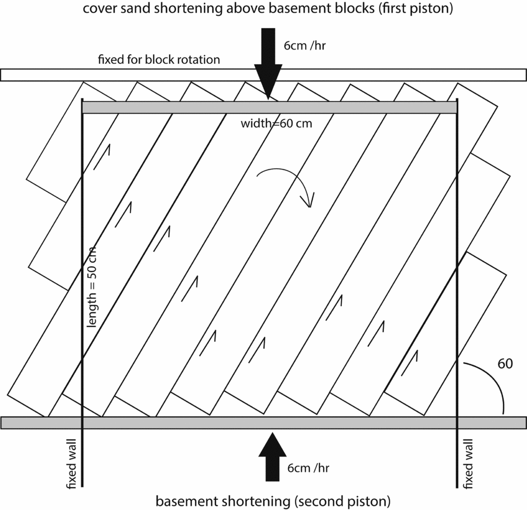
We setup and ran three models as summarized in Table 1. In the first model, cover sand shortened up to 5 cm and after that both cover and basement were simultaneously shortened. In the second model, basement was shortened up to 4 cm and blocks were rotated clockwise, which caused sinistral strike-slip faulting along the blocks, and then cover and basement were shortened simultaneously. In the third model, both cover and basement were shortened simultaneously from the beginning (Table 1).
Model parameters
Our models consist of two parts: an upper part which consists of a 60 cm by 50 cm and 1.5 cm thick sand layer that represents the cover sequence, and a lower part of rigid parallel blocks, placed on a rigid table, simulating basement blocks. These rectangular Plexiglas blocks were placed parallel to each other and their rotation caused strike-slip faulting in the basement. To be able to rotate the blocks and introduce strike-slip kinematics, we set them on the table obliquely to the shortening direction with an angle of 30° and pushed them parallel to the cover shortening direction (Fig. 2). The basement blocks were not shortened, as they were rigid, but instead rotated as they were pushed oblique to their long axis.
The material used in our models was quartz sand, which is widely used in analogue experiments to simulate brittle deformation of cover sediments in nature (Davy & Cobbold, Reference Davy and Cobbold1991; Weijermars, Jackson & Vendeville, Reference Weijermars, Jackson and Vendeville1993; Koyi & Petersen, Reference Koyi and Petersen1993; Nilforoushan et al. Reference Nilforoushan, Koyi, Swantesson and Talbot2008). The sand used has an internal coefficient of friction of 0.73 (angle of internal friction 36°) measured in the same way as in Maillot & Koyi (Reference Maillet and Koyi2006), a bulk density of 1550 kg m−3, a cohesive strength of 140 Pa and an average grain size of about 35 mm (Cotton & Koyi, Reference Cotton and Koyi2000).
To shorten both the cover and the basement, two motor-driven pistons on opposite sides were used, and the rate of shortening was averaged to 6 cm hr−1 for both cover and basement. To record and monitor the top surface deformation of the models, we installed a laser scanner on top of the models and collected 3D data at various stages as shown in Figures 3–5.
Laser scanned image of the top surface topography of Model 1 at different stages of deformation. Interpretations of the surface structures are outlined in some of the images to allow the reader to compare uninterpreted model surfaces with our interpretations. Stage A – cover 5 cm (10%) and basement 0 cm shortened. Stage B – cover 7 cm (14%) and basement 2 cm (4%) shortened. Stage C – cover 10 cm (20%) and basement 5 cm (10%) shortened. Stage D – the final stage in which cover of 16 cm (32%) and basement of 9 cm (18%) were shortened. Dashed lines are projections of the actual location of boundaries (faults) between basement blocks which show rotation with progressive deformation (compare stages B and D). Note also the shift between the actual location of basement faults and their traces in the cover structures. Circles outline bends in the trend of the cover structures giving them a wavy trend. Colour scale and axis are in millimetres.

4. Scaling
The models presented in this study are scaled to natural prototypes geometrically, kinematically and also partially dynamically (Table 2). Geometric similarity (length ratio) was fulfilled by using a thickness ratio of approximately (3×10⁻⁶) where 1 cm of loose sand in the models simulates 3 km of sediments in nature. Kinematic similarity was approached by testing three different scenarios in basement fault movement versus cover shortening. No syn-kinematic sedimentation or erosion was simulated in the models.
Scaling parameters
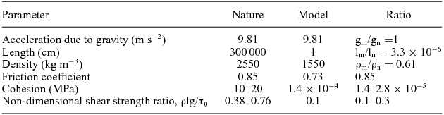
Partial dynamic similarity was fulfilled by simulating physical properties of the sedimentary rocks with appropriate modelling materials. In this respect, the intrinsic material properties, such as the coefficient of cohesion (τ0) and the coefficient of internal friction (μ), in the model and nature need to be approximated (Koyi & Peterson, Reference Koyi and Petersen1993; Weijermars, Jackson & Vendeville, Reference Weijermars, Jackson and Vendeville1993). The angle of internal friction of rocks in the upper crust (< 10 km) is averaged to 40° (Brace & Kohlstedt, Reference Brace and Kohlstedt1980), which gives a coefficient of internal friction (μ) of 0.85. The angle of internal friction of the uncompacted loose sand used in the models is 36° giving a coefficient of internal friction of 0.73 (Koyi, Reference Koyi2001; Koyi & Vendeville, Reference Koyi and Vendeville2003; Maillot & Koyi, Reference Maillet and Koyi2006), which is very close to rocks in the upper crust. Cohesion on the other hand is scaled by equality between the non-dimensional shear strength both in the model and nature:
 $$\begin{equation}
{\left( {{\rm{\rho lg/}}{{\rm{\tau }}_{\rm{0}}}} \right)_{\rm{m}}}\;{\rm{ = }}\;{\left( {{\rm{\rho lg/}}{{\rm{\tau }}_{\rm{0}}}} \right)_{\rm{n}}}
\end{equation}$$
$$\begin{equation}
{\left( {{\rm{\rho lg/}}{{\rm{\tau }}_{\rm{0}}}} \right)_{\rm{m}}}\;{\rm{ = }}\;{\left( {{\rm{\rho lg/}}{{\rm{\tau }}_{\rm{0}}}} \right)_{\rm{n}}}
\end{equation}$$
where, ρ is density, l is length, g is the acceleration due to gravity, and subscripts m and n denote the model and nature, respectively. This non-dimensionalized ratio was calculated for the model and nature using a shear strength of sedimentary rocks ranging between 1 and 10 MPa (Hoshino et al. Reference Hoshino, Koide, Inami, Iwamura and Mitsui1972). However, Schellart (Reference Schellart2000) reported that values of the cohesion of rocks in nature range between 20 and 110 MPa. For clastic sediments, we have taken the shear strength to be ranging between 10 and 20 MPa and the density to be 2550 kg m−3. Our loose sand acquired cohesion during scraping. Its cohesion is c. 140 Pa and its density is 1550 kg m−3. These figures give the non-dimensional shear strength in equation 1 a value of 0.1 and 0.38–0.76 for the model and nature, respectively. These two ratios, which are within the same order of magnitude, suggest that our models approximate dynamic similarity with a natural prototype.
5. Results
Several models were prepared in this study. The results of only three of these models (models 1, 2 and 3 in Table 1) are presented here.
In Model 1, where cover shortening (thin-skinned shortening) preceded strike-slip movement along basement faults, a series of imbricate thrusts and folds formed parallel to the pushing wall during thin-skinned shortening (Fig. 3). After formation of these structures, in addition to shortening of the cover units, basement faults were activated by rotation of the basement blocks. During this stage of deformation, most imbricates possessed a wavy pattern in the immature foreland. Further, basement shortening amplified the effect of strike-slip faults, which displaced the fore- and back-thrusts bounding the newly formed frontal imbricate. This frontal imbricate was thus dissected into rhombic structures (Fig. 3d). However, the effect of the basement strike-slip faults was not directly visible in the hinterland structures of the model.
In Model 2, rotation of basement blocks before any thin-skinned shortening of the cover units resulted in reactivation of basement faults, which were transmitted to the cover units (Fig. 4). Subsequent deformation, which included continued reactivation of basement faults and simultaneous cover shortening, resulted in formation of imbricates with wavy strike, dissected into rhombic structures along the basement faults. The surface trace of the basement faults can be followed from the foreland all the way to the hinterland of the model.
Laser scanned image of the top surface topography of Model 2 at different stages of deformation. Interpretations of the surface structures are outlined in some of the images to allow the reader compare uninterpreted model surfaces with our interpretations. Stage A – cover 0 cm and basement 3 cm (5%) shortened. Note the surface trace of the basement faults in the early imbricates in the hinterland. Stage B – cover 7 cm (14%) and basement 9 cm (18%) shortened. Stage C – cover 10 cm (20%) and basement 12 cm (24%) shortened. Stage D – the final stage in which cover of 13 cm (26%) and basement of 14.5 cm (29%) were shortened. Note the absence of the surface trend of the basement faults in the hinterland. Dashed lines are projections of the actual location of boundaries (faults) between basement blocks which show rotation with progressive deformation (compare stages B and D). Note also the shift between the actual location of basement faults and their traces in the cover structures. Cover structures show a strong wavy trend. Small arrows outline segments of basement fault traces, which show a change in trend towards the foreland. Colour scale and axis are in millimetres.

In Model 3, rotation of basement blocks simultaneously with thin-skinned shortening of the cover units resulted in transmission of movement of the basement strike-slip faults to the developing imbricates within the cover units (Fig. 5). These imbricates showed a wavy pattern displaced by basement faults. With subsequent deformation, the deformation front propagated towards the foreland where new imbricates formed with a wavy strike. The foreland imbricates were dissected into rhombic structures along the basement faults. In the final stages of deformation, the surface impression of the basement faults was more visible in the foreland imbricates than in the hinterland. In contrast to Model 2, the traces of the basement faults are not as well defined in the cover units in this model, nor the rhombic structures as clearly outlined in the cover.
Laser scanned image of the top surface topography of Model 3 in which cover and basement shortened simultaneously. Stages A, B, C and D are cover shortening at 2 cm, 8 cm 11.5 cm and 17 cm (4%, 16%, 23% and 34%), respectively. The small arrows in D outline segments of the trace of basement faults in the cover. Interpretations of the surface structures are outlined in some of the images to allow the reader to compare uninterpreted model surfaces with our interpretations. Dashed lines are projections of the actual location of boundaries (faults) between basement blocks, which show rotation with progressive deformation (compare stages A, B and D). Note also the shift between the actual location of basement faults and their traces in the cover structures. Circles outline bends in the trend of the cover structures giving them a wavy trend. Colour scale and axis are in millimetres.

In all models, the surface trends of the basement faults do not maintain a constant value. In general, the trends form a larger angle with the shortening direction in the hinterland than in the foreland where the angle is smaller (Figs 4–6). Measurements of the traces of the basement faults in the cover units after some shortening and basement block rotation show that they start at c. 40° and rotate to c. 70° to the shortening direction in the final stages of deformation (Figs 4–6).
Plots of angle of actual location of basement faults and their traces in the cover units for (a) Model 2 and (b) Model 3 with percentage of cover shortening. The plots show that both the actual location of the basement faults and their traces in the cover rotate during shortening. However, the trace of the basement faults in the cover rotate more than the basement faults indicating a foreland-ward shift of the trace of the basement faults with progressive shortening.

6. Discussion
6.a. Field observations
The Alborz Mountains and the Zagros fold-and-thrust belt, forming the northern and southern mountain ranges across the Iranian plateau, are excellent examples of coeval strike-slip and compressional deformation (Hessami, Koyi & Talbot, Reference Hessami, Koyi and Talbot2001; Allen et al. Reference Allen, Ghassemi, Shahrabi and Qorashi2003; Guest et al. Reference Guest, Axen, Lam and Hassanzadeh2006). Below, we describe some structural patterns and their distribution in the west-central Alborz Mountains and the southeastern-most parts of the Zagros fold-and-thrust belt, to show the influence of basement strike-slip faults and their associated block rotation in shaping cover deformation within orogenic belts.
The influence of block rotation and their associated strike-slip faults in accommodating shortening of the basement blocks and in lateral offset of the cover features have been demonstrated in several mountain belts (e.g. England & Molnar, Reference England and Molnar1990; Kuhn & Reuther, Reference Kuhn and Reuther1999; Hollingsworth et al. Reference Hollingsworth, Jackson, Walker, Gheitanchi and Bolourchi2006). Lateral offset of fold axes and geomorphic features along the strike-slip faults in both the Alborz Mountains (e.g. Bachmanov et al. Reference Bachmanov, Trifonov, Hessami, Kozhurin, Ivanova, Rogozhi, Hademi and Jamali2004; Ritz et al. Reference Ritz, Nazari, Ghassemi, Salamati, Shafei, Solaymani and Vernant2006; Solaymani Azad, Ritz & Abbassi, Reference Solaymani Azad, Ritz and Abbassi2011) and Zagros fold-and-thrust belt (e.g. Barzegar, Reference Barzegar1994; Hessami, Koyi & Talbot, Reference Hessami, Koyi and Talbot2001; Joudaki, Farzipour-Saein & Nilfouroushan, Reference Joudaki, Farzipour-Saein and Nilfouroushan2016) have also been frequently demonstrated. Nevertheless, in the following discussion we have made an attempt to use model results and the rhomb-shaped features observed in nature to recognize the coeval shortening of the cover sediments and rotation of the basement blocks in both the Zagros fold-and-thrust belt and the Alborz Mountains where the regional strain field involves both left-lateral faults and thrusts.
6.a.1. Alborz Mountains
Rhombic blocks in the west-central Alborz can easily be seen on geological maps (Fig. 7). These structures are bound on four sides by oblique faults with both dip and strike displacements. In general, the faults are oblique thrusts with left-lateral slip and different degrees of obliquity. Some of these faults have experienced a dextral sense of movement before possessing their current sinistral kinematics (Guest et al. Reference Guest, Axen, Lam and Hassanzadeh2006). Applying the model results to the Alborz, we suggest that these rhombic blocks must have formed owing to interaction between basement faults and cover shortening. The trend of the basement faults which could provide clockwise rotation of basement blocks and sinistral motion along them during a N–S (or NNE–SSW) shortening needs to be ENE. A NNE-trending fault (Araks fault) outlined by Allen, Jackson & Walker (Reference Allen, Jackson and Walker2004) in the western Alborz shows a sinistral sense of movement and is a basement structure. However, even though the presence of ENE-trending basement faults may explain some of the fault kinematics in the western Alborz and formation of the rhombic structures, we keep this explanation as an unsupported alternative since basement faults with such a trend have not been widely documented in previous studies. However, clockwise rotation of blocks about vertical axes is supported by recent global navigation satellite system (GPS) measurements in and around the Alborz Mountains which show the western side of the Alborz is obliquely shortening (NNE) and rotating clockwise (Djmaour et al. Reference Djamour, Vernant, Bayer, Nankali, Ritz, Hinderer, Hatam, Luck, LeMoigne, Sedighi and Khorrami2010; Mousavi et al. Reference Mousavi, Walpersdorf, Walker, Tavakoli, Pathier, Nankali, Nilfouroushan and Djamour2013). Moreover, the new stress map of Iran, which was deduced from both seismic and geodetic data, also illustrates the oblique shortening in the western side of the Alborz (Zarifi, Nilfouroushan & Raeesi, Reference Zarifi, Nilfouroushan and Raeesi2014). The simultaneous clockwise rotation and shortening of the simulated cover sediments in our models loosely mimics the current tectonic situation in the western side of the Alborz where interaction between the rotating basement blocks and cover shortening results in the formation of rhombic structures (Figs 3–7). The clockwise rotation of the basement blocks can explain the inconsistencies observed in the recently proposed kinematic models (Allen et al. Reference Allen, Ghassemi, Shahrabi and Qorashi2003; Guest et al. Reference Guest, Axen, Lam and Hassanzadeh2006) for the west-central Alborz Mountains. A second alternative for the basement kinematics is having left-lateral movement along range-parallel (i.e. NW–SE) basement faults. However, such an alternative fails on two accounts relative to the observations; first, NW–SE-trending basement faults rotate anticlockwise, not clockwise, during N–S (or NNE–SSW) shortening, and secondly, during their anticlockwise rotation, they acquire a dextral, not sinistral sense of movement. The fact remains though that the rhombic structures are bounded by faults with oblique kinematics. Field evidence indicates that the left-lateral faults are not pure strike-slip faults but that a reverse component accompanies the left-lateral faults in the west-central Alborz range (Guest et al. Reference Guest, Axen, Lam and Hassanzadeh2006; Yassaghi & Naeimi, Reference Yassaghi and Naeimi2011). Such observations indicate that oblique NNE–SSW shortening across the range is not partitioned into parallel pure left-lateral strike-slip faults and thrusts across the Alborz Mountains (since strike-slip faults and thrusts are not parallel). Thus, we suggest partitioning of strain along oblique slip thrusts and strike-slip faults which form and evolve owing to interaction between basement fault activation, rotation of basement blocks and cover shortening during thick-skinned shortening in the western Alborz range.
Geological map of the western Alborz Mountains showing rhomboic structures. These structures indicate clockwise rotation of basement blocks about vertical axes (see Fig. 1 for location).

6.a.2. Zagros fold-and-thrust belt
A number of strike-slip faults which are consistent with the alignments of salt plugs and distort the fold axes in the sedimentary cover have long been identified by early workers (McQuillan, Reference McQuillan1973, Reference McQuillan1991; Fürst, Reference Fürst1990; Barzegar, Reference Barzegar1994; Edgell, Reference Edgell, Alsop, Blundell and Davison1996) (Fig. 8 Figure 8b shows two domains of strike-slip faults crossing the Zagros belt; the western domain is trending NNW while the eastern domain is NE. The left-lateral sense of motion along the faults in the eastern domain (NE faults) has been interpreted to result from clockwise rotation of fault-bounded basement blocks about vertical axes (Hessami, Koyi & Talbot, Reference Hessami, Koyi and Talbot2001). However, Aubourg et al. (Reference Aubourg, Smith, Bakhtari, Guya, Eshragi, Lallemant, Molinaro, Braud, Delaunay and Sussman2004) disregarded the proposed block rotation and attributed the left-lateral ‘shear band’ across the southeastern-most Zagros to the Oman peninsula acting as an indenter. Here we use observations of the deformation pattern in the southeastern-most part of the Zagros to support our previous suggestion of clockwise rotation of basement blocks there. Cover structures in the SE Zagros are mainly displayed as E–W whale-back anticlines (Fig. 9). Some of these anticlines are bounded or bent by NE-trending strike-slip faults (Fig. 8a).
(a) Geological map of the SE Zagros fold-and-thrust belt (see Fig. 1 for location), showing distribution of salt diapirs (red spots), strike-slip faults and whale-back anticlines deformed as rhomboid blocks (denoted by ‘R’) along the strike-slip faults. (b) Simplified map of the Zagros fold-and-thrust belt showing major discrete orogenic zones and major strike-slip faults. Right-lateral faults trend NNW while left-lateral faults, dominant in the southeastern-most part of the belt, are trending NE.

DEM view of (a) left-lateral displacements and (b) right-lateral displacement of fold axes and development of rhomboid structures (whale-back anticlines) in the SE Zagros.

The rhombic structures are not well visible in the Zagros fold-and-thrust belt. This could partly be due to a different combination of regional shortening/strike-slip regimes. Here, we show that post-shortening strike-slip movements along the basement faults have little influence on the structural evolution of the cover units. Across the Zagros fold-and-thrust belt, several along-strike zones of discrete deformation episodes have been recognized which have propagated from the NE to the SW since Cretaceous time to the present (Falcon, Reference Falcon and Spencer1974; Hessami et al. Reference Hessami, Koyi and Talbot2001; Agard et al. Reference Agard, Omrani, Jolivet, Whitechurch, Vrielynck, Spakman, Monié, Meyer, Wortel, Lacombe, Grasemann and Simpson2011). As can be seen from Figure 8b, most of the transverse strike-slip faults in the cover (such as the Karebas, Sabzpoushan and Sarvestan right-lateral faults and many other left-lateral faults in the southeastern-most part of the Zagros) appear to terminate at the SW limit of the High Zagros. The fact that no continuations of these faults are recognized in the High Zagros suggests either that some of the strike-slip faults in the basement were reactivated after the deformation across the High Zagros and the Sanandaj–Sirjan Zone, and/or their impact is obscured by the thickened hinterland. Results of Model 1, which show a resemblance to the Zagros fold-and-thrust belt, could be used to interpret the structural relationship between the cover and basement in this belt. However, caution is needed in applying the model results to the Zagros fold-and-thrust belt. The tectonically thickened hinterland may obscure the impact of the basement strike-slip faults on cover sediments, which can be up to 12 km thick in this part of the belt. In addition, a greater amount of rotation of the fault traces in the cover units in the hinterland, which has undergone larger amounts of shortening, may display the traces as oblique thrusts rather than strike-slip faults. Along these rotated strike-slip traces, a greater amount of dip-slip is expected to be accommodated during the collision converting them to oblique thrusts rather than strike-slip faults. Furthermore, a greater amount of erosion in the uplifted hinterland may obscure the surface traces of the basement strike-slip faults (i.e. their surface expressions).
On the other hand, the model results indicate that pre- and syn-orogenic activity along basement strike-slip faults show a great impact on the structural pattern of the cover units in fold-and-thrust belts. Some of the most prominent basement strike-slip faults such as the Kazerun fault seem to have been active before and/or coeval with the formation of the High Zagros belt, which has been offset along the northern segment of the Kazerun fault (known also as Dena fault) (Fig. 8b). However, as can be seen from Figure 8 the surface expression of the other right-lateral faults (i.e. the Karebas, Sabzpoushan and Sarvestan faults) is deviated significantly from a straight and continuous line into several left-stepping fault segments while the left-lateral faults (restricted mainly to the southeastern-most Zagros) stepped right (Fig. 8a). This can be interpreted as apparent displacement (i.e. separation) of oblique strike-slip faults along folds and thrusts in the foreland as the cover shortens with time.
The less well-developed rhombic structures in the Zagros could also be due to the spacing of the strike-slip faults. Large spacing between basement strike-slip faults does not promote the formation of such rhomboid structures. In the case of widely spaced basement faults, shortening structures in the cover (anticlines, thrusts and thrust-related anticlines) develop in areas between the widely spaced strike-slip faults not directly confined by the basement faults. Instead, they are displaced, or bent across the traces of basement faults.
Another reason for the less developed rhombic structures in the Zagros can be due to the degree of (de)coupling between cover units and the basement. Large parts of the southwestern-most segment of the Zagros fold-and-thrust belt are floored by a thick layer of Hormuz salt, which deforms in a ductile way. Moreover, in addition to thick carbonate formations, the Zagros stratigraphy includes several horizons of thick and less-competent units of salt, shale and marl. Basal Hormuz salt and the less-competent units within the Zagros stratigraphy may decouple the basement from the cover units preventing basement faults from directly propagating upwards into the surface. Displacement along basement faults may be ‘refracted’ across the less-competent units and initiate a relatively wider deformation zone within the cover units. It is important to underline here that some of the basement faults may have been active throughout the evolution history of the Zagros where both simultaneous sedimentation and basement fault movement have taken place. In addition to Hormuz salt, the Zagros stratigraphy includes several mechanically weak formations with substantial thickness of Late Jurassic (Hith Formation) and Early Miocene (Gachsaran Formation) ages (Blanc et al. Reference Blanc, Allen, Inger and Hassani2003; Sherkati & Letouzey, Reference Sherkati and Letouzey2004; Sepehr & Cosgrove, Reference Sepehr and Cosgrove2005; Farzipour-Saein et al. Reference Farzipour-Saein, Yassaghi, Sherkati and Koyi2009), which may have acted as a decoupling agent between the deeper and shallower units in the Zagros fold-and-thrust belt and decreased the impact of basement faulting on the cover and its upwards propagation. And finally, another probable reason for the missing well-developed rhombic structures in the Zagros is the type of deformation and the nature of structures which formed during shortening in the cover, especially in the Simply-Folded Zone and foreland of the belt. Even though many of the anticlines in the Zagros fold-and-thrust belt are thrust related, some of the folds in the Zagros are detachment folds and thereby with less well-defined thrusts. Such structures show deflection rather than rhombic structures. Bends in the trends of folds in the Zagros are well documented and attributed to strike-slip movement along basement faults (Fig. 9a, b) (Hessami, Koyi & Talbot, Reference Hessami, Koyi and Talbot2001; Sepehr & Cosgrove, Reference Sepehr and Cosgrove2004; Authemayou et al. Reference Authemayou, Bellier, Chardon, Malekzade and Abbassi2005).
6.b. Rhombic versus flower structures
The rhombic structures are similar in appearance to positive flower structures. Similar to flower structures, the rhombic structures are bounded on two opposite sides by thrusts (or oblique thrusts) and on the other two sides by strike-slip faults (oblique faults), which are partly overstepped. They develop positive topographies. However, there are some fundamental differences between these two types of structures.
(a) The most obvious difference is that the rhombic structures differ in the sense of movement along the bounding strike-slip faults. A positive flower structure forms as a result of a left-step overlap between two dextral strike-slip fault segments, or a right-step overlap between two sinistral strike-slip fault segments. However, in the rhombic structures described in this study, the two sinistral strike-slip fault segments overlap in a left-step configuration, which should form a structural low (negative flower structure) instead of a structural high. Applying this concept to the Alborz, where such structural highs are documented, reveals some fundamental elements for their formation. In order to form a positive flower structure, the strike-slip faults in the Alborz, which are in a left-step configuration, need to be dextral, not sinistral. As such, they are not a classic positive flower structure.
(b) A second difference between the two kinds of structures is the dip direction of the thrusts. Unlike in positive flower structures, where the thrusts dip towards each other, dip direction of thrusts in the rhombic structures can vary depending on which types of thrusts (fore- or back-thrusts) the strike-slip faults cross; when strike-slip faults cross two adjacent fore-thrusts, the opposite thrusts within the rhombic structure dip in the same direction towards the hinterland; when strike-slip faults cross a fore- and back-thrust pair, the opposite thrusts within the rhombic structure dip in towards each other similar to ‘regular’ flower structures or dip away from each other if the fore-thrust is located in the hinterland side of the back-thrust; and strike-slip faults cross-cutting two adjacent back-thrusts produce a rhombic structure where thrusts dip in the same direction towards the foreland. Some of these different combinations are seen in the Alborz Mountains (Fig. 7). One of the rhombic structures in the Alborz, located directly north of Tehran (Fig. 7), shows thrusts dipping in the same direction (i.e. northwards, this is an exceptional case). This structure must be the product of a combination of two strike-slip faults cutting across two adjacent fore-thrusts. This is because the thrusts are the result of regional shortening, not a local shortening due to strike-slip faulting.
(c) A third difference between the two structures is the relationship between the thrusts and strike-slip fault segments. In ‘regular’ flower structures, thrusts are bounded by the strike-slip faults, i.e. the thrusts form and are active only within the area bounded by the strike-slip faults. This does not seem to be the case in the Alborz where the thrusts associated with the rhombic structures seem to cut/displace the strike-slip faults that bound the same rhombic feature. In other words, the thrusts are not confined to the area defined by the strike-slip fault segments.
(d) Thrusts in flower structures form as a result of movement along the strike-slip faults, and as stated above, are confined within the area of the influence of the latter. Thrusts in the rhombic structures seen in the Alborz are not a product of movement along the strike-slip faults, but have formed owing to regional shortening. Actually, both formation of the thrusts and movement along the strike-slip faults are the product of the regional shortening caused by collision.
Our models show that the thrust segments bounding the rhombic structures rotate with progressive deformation to trends oblique to the bulk shortening direction (Figs 3–6). Their rotation leads to initiation of oblique rather than pure dip-slip along them. The degree of oblique slip along these thrusts depends on the degree of their rotation. As such, these thrusts which formed as dip-slip faults would acquire a component of strike-slip along them albeit dip-slip being the main slip component. The same is true for the strike-slip segments bounding the rhombic structures. The strike-slip faults acquire some component of dip-slip as they rotate and thus become oblique slip faults (Figs 3, 4). Such oblique slip faults (both thrust and strike-slip segments bounding the rhombic structures) are observed in the Alborz Mountains (Fig. 7).
6.c. Basement faults and their surface traces
The model results show that basement faults leave a stronger impact on the cover when they are active prior to cover shortening. In this case, basement faults form clear traces in the cover and are incorporated within the structures formed during cover shortening (Model 2; Fig. 4). When cover shortening precedes basement fault movement, the impact of basement faulting is most visible through the local bends in the cover structures in the foreland. Their impact in the hinterland is not clear (Model 1; Fig. 3). However, during simultaneous basement faulting and cover shortening, the impact of basement faults is visible as bends in the cover structures and less basement traces develop in the cover units (Model 3; Fig. 5). In contrast to Model 2, the traces of the basement faults are less well defined in Model 3, and the rhombic structures are less clearly outlined. These differences are probably due to the fact that rigid block rotation started from an earlier stage prior to any cover shortening in Model 2 compared to Model 3, where basement fault rotation was simultaneous with cover shortening. Cover shortening seems to have diminished and/or overprinted the effect of basement block rotation.
Model results show that the trends of the surface expression of the basement wrench faults in the cover change with progressive shortening (Fig. 6). When basement faulting is prior to or is simultaneous with cover shortening, the trends of the surface expression of the basement faults change from the hinterland to the foreland. The surface trends form a larger angle with the shortening direction in the hinterland than in the foreland where the angle is smaller (Figs 4, 5). Measurements of traces of the basement fault in the cover units after some shortening and basement block rotation show that they start at c. 40° and rotate to c. 70° to the shortening direction at the final stages of deformation (Figs 4–6). Rotation of the wrench trace is less likely to solely be due to the rotation of the basement blocks and could also be caused by deformation within the cover structures (imbricates/folds) that thicken and shorten with progressive deformation. As the fault traces rotate, they increase their angle to the shortening direction. As a result, they acquire a larger component of dip-slip and accommodate part of the cover shortening. As such, the traces of the basement faults in the cover are not pure strike-slip, but oblique slip (Figs 3–5). Such oblique slip is shown along some of the ‘strike-slip’ faults in the Alborz, which are trending at a high angle to the shortening direction of the belt (Fig. 7).
The traces of the basement wrench faults do not only rotate, but are also shifted forwards towards the foreland. This ‘shift’ of traces in the cover units rooted in basement wrench faults towards the foreland, if not accompanied by the same amount of deformation in the basement, may lead to mismatch between the actual position of a basement fault at depth and its trace in the cover units (Fig. 6). Basement traces picked out in the models do not coincide with the actual projected location of the basement faults (Figs 3–6) indicating a faster foreland ‘migration’ of the traces than the rate at which the basement blocks (hence the faults bounding them) rotate. Both the rotation of surface traces of basement faults, and their deformation and forward migration with the cover structures have significant implications for correct identification of position and orientation of the basement faults that create them. Traces of basement faults depicted in the cover units in the Zagros may not represent the surface projection of the actual basement faults. It is easier to link surface traces with basement faults which are seismic through their fault plane solutions. However, aseismic basement faults and uncertainty in positioning the focal mechanism of seismic faults renders the match between basement faults and their surface traces difficult.
Basement faults which form a high angle to the strike of cover structures (i.e. small angle to the direction of bulk shortening) form traces which rotate less and migrate relatively close to the basement fault. This situation was demonstrated clearly in the models conducted by Rosas et al. (Reference Rosas, Duarte, Schellart, Tom, Grigorova and Terrinha2014) where the basement fault was parallel to the shortening direction (i.e. almost orthogonal to the trend of the cover thrusts).
7. Conclusions
Model results helped to define the tectonic link between basement strike-slip faults and deformation in cover units in natural fold-and-thrust belts such as the Alborz and Zagros mountains.
-
(1) Basement block rotation about their vertical axes, their timing and their associated strike-slip faults have a great impact on the pattern of cover deformation in fold-and-thrust belts. Aside from displacing surface structures in a strike-slip mode, rotation of basement blocks prior to or simultaneously with cover shortening results in the formation of cover blocks that exhibit rhombic shapes. These rhombic blocks are totally different in genesis from positive flower structures which develop in transfer zones, where displacement is conveyed from one fault segment to another in systems of stepped strike-slip faults. In other words, the coeval activity of oblique basement strike-slip faults and shortening of the overlying cover leads to the formation of a typical structural pattern which could not be solely formed along straight strike-slip faults.
-
(2) The typical rhombic pattern produced in the models can be used to derive the kinematic models of the active crustal deformation in fold-and-thrust belts. This pattern we recognized in the southeastern-most part of the Zagros coincides completely with the previous claims of clockwise rotation of basement blocks about vertical axes. The rhombic pattern we detected within the central-west Alborz may suggest clockwise rotation of basement blocks about vertical axes resulting in left-lateral motion along faults bounding the blocks contemporaneous with N–S shortening of the cover.
-
(3) Interaction between traces of the basement faults and thrusts in the cover result in bending of the surface expression of structures, including folding, and may give a wavy pattern to the deformation front of a fold-and-thrust belt.
-
(4) Model results show that the accurate location of basement strike-slip faults is often disturbed by the cover structures overriding and/or deforming their surface traces as the deformation front migrates forwards. Thus, our models can be invoked to map the locations of the basement faults where obscured beneath the cover.
Acknowledgements
Constructive and detailed comments of Filipe M. Rosas improved both the content and presentation of this article. We also thank the Editor Jonas Ruh for help during handling of the manuscript. HAK and FN are funded by the Swedish Research Council (VR).


