


Nomenclature
- t
-
core material thickness of CKW
- h
-
cell height of CKW
- l
-
cell length of CKW
- θ
-
internal cell angle of CKW
- EI
-
flexural stiffness
- N
-
each normalised value
- Nm
-
normalised value for wingbox mass
- Nf
-
normalised value for flutter speed
- Nd
-
normalised value for maximum deformation displacement
- X
-
each computed value within the initial dataset
- X best
-
the best value among the initial dataset
- X worst
-
the worst value among the initial dataset
- f(θ, t)
-
Bayesian optimisation objective function
- m
-
the weight for wingbox mass
- f
-
the weight for flutter speed
- d
-
the weight for maximum deformation displacement
1.0 Introduction
Micro unmanned aerial vehicles (micro-UAVs) have become a focal point in aerospace research due to their small size, operational flexibility and applicability in constrained or dynamic environments [Reference Ahmed, Mohanta, Keshari and Yadav1]. Among them, morphing wing UAVs enable adaptive changes in wing geometry during flight, which can improve aerodynamic performance under varying flight conditions and expand mission capabilities [Reference Barbarino, Bilgen, Ajaj, Friswell and Inman2]. In the design of fixed-wing micro-UAVs, aspect ratios are commonly lower than those of full-scale aircraft, typically ranging from 1 to 4, to accommodate structural compactness, increase manoeuverability and improve gust response under low Reynolds number conditions [Reference McMichael3, Reference Zufferey, Klaptocz, Beyeler, Nicoud and Floreano4]. Additionally, in small-scale and flexible wing structures, it is often observed that torsional, in-plane and bending natural frequencies lie within a similar range due to the relatively uniform stiffness distribution and low mass, which can lead to mode coupling and reduced frequency separation [Reference Livne5, Reference Wright and Cooper6].
The cellular wingbox structure, inspired by natural honeycomb configurations, utilises a lattice framework made from high-strength, lightweight materials, optimising weight and strength. This structure’s flexibility accommodates mechanical stresses from in-flight shape changes, maintaining structural integrity and aerodynamic efficiency [Reference Heo, Ju and Kim7]. For the manufacturing of UAVs, additive manufacturing technology has been widely adopted due to its ability to utilise various materials to create lightweight structures with complex geometric shapes [Reference Goh, Agarwala, Goh, Dikshit, Sing and Yeong8]. However, Kirigami techniques hold a distinct advantage in terms of adaptively deforming according to aerodynamic demands. This advantage stems from their ability to introduce controlled hinge points within the material, which enable the structure to morph dynamically [Reference Callens and Zadpoor9, Reference Zhai, Wu and Jiang10]. The integration of the cellular wingbox structure with Kirigami techniques provides a cutting-edge approach for the design of morphing wing UAVs. This combination enhances flexibility and tailor-made mechanical properties, making it highly suitable for UAVs operating in diverse and demanding environments [Reference Saito, Agnese and Scarpa11].
Aeroelastic analysis of the cellular Kirigami wingbox (CKW) structure constitutes a pioneering effort within the field. Prior to this, Li et al. [Reference Li, Ainsworth, Allegri, Yuan and Scarpa12] had made a preliminary estimation of the divergence speed of CKW structures using analytic equations. Comparable aeroelastic studies include the research by Leitch et al. [Reference Leitch, Yuan and Stodieck13] on continuous tow sheared structures, Rivero et al. [Reference Rivero, Weaver, Cooper and Woods14] on fish bone active camber trailing edge devices and Wang et al. [Reference Wang, Khodaparast, Friswell and Shaw15] on the application of round corrugated panels in the compliant structure. Conducting aeroelastic analysis on such an innovative structure as the CKW is crucial for ensuring structural integrity and operational safety. This encompasses both static aeroelasticity and flutter analysis. Static aeroelasticity evaluates how the wingbox structure deforms under steady aerodynamic forces. Flutter analysis explores the dynamic interactions between aerodynamic forces, structural elasticity and inertia, which are essential for assessing the wingbox structure’s resistance to destructive vibrations that could precipitate catastrophic failure. Collectively, these analyses are vital for defining safe operational thresholds and enhancing the reliability of the wingbox structure under diverse flight conditions, thus proving indispensable in the design process of the wingbox structure [Reference Wright and Cooper6].
The application of Bayesian optimisation to the innovative design of the CKW structure enhances both the novelty and research value of this work. Utilising Bayesian optimisation for parameter tuning in CKW structures significantly enhances design efficiency and effectiveness. This optimisation method leverages probabilistic models to predict and evaluate the performance of various design configurations, reducing the need for extensive physical testing. Compared to conventional strategies such as genetic algorithms, which often require a large number of function evaluations and are less sample-efficient, Bayesian optimisation offers a more data-efficient and computationally economical approach. This is particularly beneficial when each design evaluation involves high-fidelity finite element simulations [Reference Forrester, Sobester and Keane16–Reference Snoek, Larochelle and Adams18]. Bayesian optimisation has been widely applied in wing design; for example, Jim et al. [Reference Jim, Faza, Palar and Shimoyama19] optimised the wing design of supersonic aircraft using Bayesian optimisation to effectively balance aerodynamic performance and reduce noise. In another study, Saporito et al. [Reference Saporito, Da Ronch, Bartoli and Defoort20] employed Bayesian optimisation for the design of flexible aircraft, considering dynamic aeroelastic constraints such as flutter and gust loads, and uncertainties in wing structural parameters, providing optimised solutions with reliability assessments. Overall, applying Bayesian optimisation to the design of the CKW structure provides an efficient solution for the high-fidelity design of complex wingboxes.
The aim of this paper is to efficiently search for optimal design parameters under different optimisation criteria using Bayesian optimisation, based on finite element analysis results of CKW with various structural parameters. To achieve this, the paper initially constructs wingbox models, detailing their geometrical parameterisation and finite element modelling. Notably, the wingbox structure will manifest as either hexagonal honeycomb or butterfly honeycomb depending on the sign of the internal cell angles. Hexagonal cells exhibit positive internal cell angles; reducing these angles decreases the Poisson’s ratio of the honeycomb. Conversely, butterfly cells, with their negative internal cell angles, display a negative Poisson’s ratio; stretching along one direction causes the honeycomb to expand perpendicular to the applied displacement. Subsequent numerical evaluations of different wingbox configurations include mesh sensitivity analysis, modal analysis, static aeroelastic analysis and flutter analysis. These evaluations yield data on the wingbox’s mass, deformation and flutter speed sensitivities relative to the internal cell angle and cell material thickness. Ultimately, initial data under various internal angles and material thicknesses are utilised for Bayesian optimisation, resulting in optimal internal angles and material thicknesses under different optimisation criteria. The primary contribution of this work is demonstrating the aeroelastic advantages of CKW structures, such as structural stability and high flutter resistance. Additionally, it establishes the feasibility of applying Bayesian optimisation to multi-objective, multidimensional design problems in high-fidelity, complex wingbox configurations.
2.0 Wingbox modeL
2.1 Geometrical parameterisation
The parameters defining the unit cell of centre-symmetric honeycomb configurations are described by Gibson and Ashby [Reference Gibson and Ashby21]. To enhance the efficiency and flexibility of the modeling process, Li et al. [Reference Li, Ainsworth, Allegri, Yuan and Scarpa12] described Matlab/CAD processing method to perform Parametric Modeling techniques. The modelling approach enables the customisation of honeycomb wingbox structures by considering input parameters like aerofoil chord length, wingbox width, distance from the core to leading and trailing edge, material thickness t, cell dimensions h and l and the internal cell angle θ. Positive values of θ result in classical hexagonal and overexpanded honeycomb configurations, while negative values lead to butterfly honeycomb architectures with negative in-plane Poisson’s ratios. The parameters t, l, h and θ are illustrated in Fig. 1.
2D geometry parameters: (a) hexagonal cell configuration, (b) butterfly cell configuration.

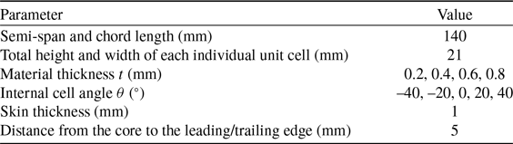
The wingbox models in this study are constructed based on the NACA 2415 aerofoil, which has been effectively utilised for low-speed MAVs [Reference Saito, Agnese and Scarpa11, Reference Genç, Kaynak and Yapici22, Reference Soylak23]. Both the wing semi-span and chord length for this configuration are set at 0.14 m. The total height and total width of each individual unit cell are consistently maintained at 0.021 m, with a 5 mm distance from the cellular core to both the leading and trailing edges. The skin thickness is set to 1 mm. These values are adopted as preliminary design parameters to ensure structural strength under reasonable operational conditions [Reference Li, Ainsworth, Allegri, Yuan and Scarpa12, Reference Thill, Etches, Bond, Potter and Weaver24], and their further exploration within a multidimensional design space is planned for future work. As the internal cell angle θ changes, the lengths h and l are proportionally scaled to preserve the number of cells and the overall geometry of the wingbox. The orientation of the wingbox’s chord length is consistent with the h dimension of the cells. The aerofoil and wingboxes with different cell configurations generated by the parametric modeling programme are depicted in Fig. 2. The study explores the impact of the internal cell angle θ within a range of −40° ≤ θ ≤ 40°. The maximum and minimum values of θ are based on the largest and smallest angles possible before wall contact becomes an issue relative to the length l. The investigation into the influence of material thickness t spans a range from 0.2 to 0.8 mm, which falls within a structurally reliable engineering range for core material polyether-ether-ketone (PEEK) and has been widely adopted in Kirigami cellular structure studies [Reference Li, Ainsworth, Allegri, Yuan and Scarpa12, Reference Chen, Scarpa, Remillat, Farrow, Liu and Leng25, Reference Del Broccolo, Laurenzi and Scarpa26]. The material thickness t is sampled at 0.2 mm intervals and the internal cell angle θ at 20° intervals to obtain a sufficiently diverse set of initial data points for Bayesian optimisation. The design parameters explored in this research are summarised in Table 1.
The schematic of the wingbox structure generated by the parametric modeling programme includes: (a) aerofoil, (b) butterfly honeycomb configuration (θ = –20°), (c) rectangular honeycomb configuration (θ = 0°), (d) hexagonal honeycomb configuration (θ = 20°), axis units: mm.

The design parameters of the baseline CKW architectures explored in this research

2.2 Finite element modelling
Scripts generated by parametric modeling in ANSYS Design Modeler are executed to create CKW models. After this initial creation, a skin conforming to the core of the wingbox is added. The model is then converted into a shell model due to the material thickness of wingbox being significantly smaller than other dimensions. This conversion enables the use of face meshing for both the core and skin of the wingbox, instead of body meshing, thereby reducing the number of elements and nodes, accelerating processing times and enhancing the representation of structural behaviour in thin-walled areas [Reference Nguyen-Thanh, Rabczuk, Nguyen-Xuan and Bordas27]. The finite element shell models of the wingbox with skin and the wingbox cores with different cell configurations are shown in Fig. 3. As shown in Fig. 3(a), the boundary conditions of the model are depicted with a fixed support set on the edge that would connect to the fuselage, to simulate the real wing scenario.
CKW models: (a) with skin, (b) butterfly honeycomb configuration (θ = –20°), (c) rectangular honeycomb configuration (θ = 0°), (d) hexagonal honeycomb configuration (θ = 20°).

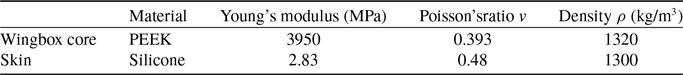
The core of the CKW utilises PEEK due to its high strength-to-weight ratio, excellent wear resistance and thermal stability. These properties enable the wingbox to achieve efficient aerodynamic performance and maintain structural integrity and durability under extreme environmental conditions [Reference Flower and Soutis28]. The skin of the CKW is made from silicone elastomers, chosen for their high elongation at break and fatigue resistance, which provide the wingbox skin with effective deformation capabilities, ensuring structural integrity under fluctuating aerodynamic loads [Reference Ahmad, Ajaj and Amoozgar29]. The wingbox design using PEEK as the core material and silicone elastomers as the skin material demonstrated favourable mechanical properties in the studies conducted by Li et al. [Reference Li, Ainsworth, Allegri, Yuan and Scarpa12]. Material properties of the CKW are shown in Table 2.
Material properties of the CKW

Following a mesh sensitivity analysis, where the modal analysis results were influenced by less than 1% due to changes in mesh size while minimising the computational resources required, this study employs a meshing size of 1.2 mm as the standard. Additionally, rigid meshing is applied to the wingbox core to control mesh quality in the corner regions of the honeycomb walls, while flexible meshing is used for the skin to accommodate its curved structure and reduce computational resources.
3.0 Numerical evaluation
3.1 Modal analysis
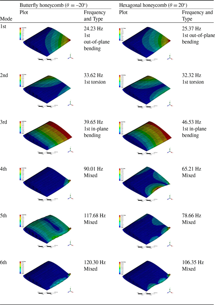
The modal analysis was performed in ANSYS. The results for the butterfly honeycomb configuration (θ = –20°) and hexagonal honeycomb configuration (θ = 20°), both with t = 0.2 mm, are presented in Table 3. The mode types and frequencies of the first three modes for both configurations are quite similar. The first mode is a first out-of-plane bending mode, with frequencies of 24.23 Hz for the butterfly configuration and 25.37 Hz for the hexagonal configuration. The second mode is a first torsion mode, with frequencies of 33.62 Hz and 32.32 Hz for the butterfly and hexagonal configurations, respectively. The third mode is a first in-plane bending mode, with frequencies of 39.65 Hz for the butterfly configuration and 46.53 Hz for the hexagonal configuration. The subsequent modes for both the butterfly honeycomb configuration and the hexagonal honeycomb configuration are all mixed modes, showing significant differences in mode types and frequencies. While the wingboxes in both configurations exhibit similarities in the lower-order modes, there are clear distinctions in the higher-order modes.
Modal analysis results for the first six modes of a CKW featuring butterfly honeycomb configuration (θ = –20°) and hexagonal honeycomb configuration (θ = 20°), both with t = 0.2 mm

3.2 Static aeroelastic analysis
Static aeroelastic analysis was performed in Nastran using SOL 144 with the results visualised in Patran. The Doublet-Lattice Method (DLM) was utilised in aerodynamic modeling to supply the necessary aero loads for aeroelastic analyses [Reference Demasi30]. In general, controlling the angle-of-attack between 0° and 6° can ensure the highest aerodynamic efficiency for UAVs [Reference Liao, Cheng, Sun, Zhao, Jia and Qi31]. Kachel et al. [Reference Kachel, Okoń, Frant and Majcher32] compared six typical micro-UAVs, all of which have maximum speed ranging from 20 m/s to 28 m/s. This study initially conducted a static aeroelastic analysis on a CKW under the conditions of an air density of 1.226 kg/m3, with the flight speed set at 20 m/s and the angle-of-attack at 5°, both of which are considered reasonable for this analysis. The deformation displacement result of the CKW with the butterfly honeycomb configuration (θ = –20°, t = 0.2 mm) is presented in Fig. 4. The deformation displacement increases in the spanwise direction from the fixed support, with the maximum displacement of 1.71 mm occurring at the trailing edge of wing tip.
Displacement distribution of the CKW with butterfly honeycomb configuration (θ = –20°, t = 0.2 mm) under aerodynamic conditions of air density 1.226 kg/m³, flight speed 20 m/s and angle-of-attack 5°, unit: mm.

To further expand the analysis on the ranges of flight speed and angle-of-attack, under aerodynamic conditions with air density maintained at 1.226 kg/m³, the flight speed was varied from 0 to 25 m/s, and the angle-of-attack ranged from 0° to 10°. The variation in maximum displacement of the CKW with the butterfly honeycomb configuration (θ = –20°, t = 0.2 mm) is shown in Fig. 5. The maximum displacement exhibits a linear relationship with the angle-of-attack and an approximately quadratic relationship with the flight speed, as aligned as in the literature [Reference Anderson33]. The peak displacement reaches approximately 5 mm, corresponding to a tip deflection of 3.57% relative to the semi-span of 140 mm. Given the elastic properties of the core material PEEK, this level of deformation remains within the expected linear-elastic range, thereby ensuring structural stability and preserving aerodynamic integrity [34].
Maximum displacement of the CKW with butterfly honeycomb configuration (θ = –20°, t = 0.2 mm) as a function of flight speed and angle-of-attack.

To investigate the effects of internal cell angle θ and material thickness t on the static aeroelastic performance of the CKW, Fig. 6 illustrates the variation in maximum displacement of the CKW within the ranges of –40° ≤ θ ≤ 40° and 0.2 mm ≤ t ≤ 0.8 mm under conditions of an air density of 1.226 kg/m³, a flight speed of 20 m/s and an angle-of-attack of 5°. It can be observed that for configurations with the same θ, the maximum displacement decreases with increasing material thickness. This is primarily because an increase in thickness enhances the flexural stiffness EI of the wingbox, leading to smaller deformations under the same external load. However, for a constant material thickness, the wingbox configurations with different θ exhibit significant variations in deformation under the same external load.
Maximum displacement of the CKW across internal cell angles θ and material thicknesses t under aerodynamic conditions of air density 1.226 kg/m³, flight speed 20 m/s, and angle-of-attack 5°.

Figure 7 presents the variation in total mass of the wingbox within the ranges of –40° ≤ θ ≤ 40° and 0.2 mm ≤ t ≤ 0.8 mm. It can be observed that the mass of the wingbox decreases significantly with increasing θ. The butterfly honeycomb configuration requires less material compared to the hexagonal honeycomb configuration. However, the monotonic decrease in mass does not result in a monotonic reduction in EI. The butterfly honeycomb configuration, which has lower mass, exhibits better deformation resistance, whereas the rectangular honeycomb configuration demonstrates the poorest deformation resistance among the studied configurations. Nevertheless, Li et al. [Reference Li, Ainsworth, Allegri, Yuan and Scarpa12] found that the rectangular honeycomb configuration of CKW exhibits the highest spanwise EI, which contradicts its poor resistance to deformation. This inconsistency arises because when the length walls fully align with the spanwise direction, it no longer contributes to EI in the chordwise direction. Consequently, this alignment leads to a decrease in chordwise EI, resulting in increased deformation at the trailing edge of the wing tip.
Total mass of the CKW across internal cell angles θ and material thicknesses t.

3.3 Flutter analysis
Flutter analysis was performed in NASTRAN using SOL 145. Figure 8(a) illustrates the variation in the natural frequencies of the first and second modes of the CKW for different internal cell angles θ as a function of flight speed, with a material thickness of t = 0.2 mm. It can be observed that, under the same flight speed, the natural frequency of the first mode is higher for configurations with θ = –20° and θ = 20°. For the second mode, the natural frequency decreases from θ = –40° to θ = 0°, then increases from θ = 0° to θ = 40°. The natural frequency of the first mode increases with flight speed, while that of the second mode decreases, leading to modal coupling when the frequencies of the two modes converge. As shown in Fig. 8(b), for all θ configurations of the CKW, the damping of the first two modes is slightly greater than zero at low speeds. As the flight speed increases, the damping of one of the modes decreases to negative upon modal coupling, at which point the vibrational energy of the system is no longer dissipated but accumulates with each vibration cycle. This accumulation causes the vibration amplitude to gradually increase, which ultimately leads to structural failure. This phenomenon marks the onset of flutter, with the flutter speed corresponding to the flight speed at which the damping becomes zero [Reference Sudha, Deodhare and Venkatraman35].
The variation in (a) the natural frequencies and (b) the damping of the first and second modes of the CKW for different internal cell angles θ as a function of flight speed, with a material thickness of t = 0.2 mm.

The curves where damping = 0 in Fig. 8(a) represent the relationship between flutter speed and θ. The flutter speed decreases initially with increasing θ, reaching a minimum value of 65 m/s at θ = 0°, before increasing again. This flutter speed is significantly higher than the maximum speed of the six typical micro-UAVs investigated by Kachel et al. [Reference Kachel, Okoń, Frant and Majcher32], among which the fastest, the RQ-11 Raven, has a maximum speed of 27.8 m/s. This indicates that the CKW in this study has a substantial design margin for flight speed, providing ample design space for high-speed applications. Furthermore, Li et al. [Reference Li, Ainsworth, Allegri, Yuan and Scarpa12] estimated the divergence speed of a CKW structure with comparable size and configuration using a theoretical expression [Reference Megson36], concluding that a structure with a 0.2 mm material thickness would diverge below 20 m/s. In contrast, the present study demonstrates that the wingbox encounters flutter prior to static divergence, and the predicted flutter speed exceeds 65 m/s, which is significantly higher than the value estimated by Li et al. This discrepancy may arise from the limitations of the theoretical formulation employed, which is derived under simplifying assumptions such as linear aerodynamic behaviour, uniform torsional stiffness and idealised beam models. These conservative assumptions are not fully applicable to the CKW configuration, which features complex geometry, distributed stiffness and coupled deformation characteristics that are better represented through finite element modelling.
The variation in flutter speed of the wingbox within the ranges of –40° ≤ θ ≤ 40° and 0.2 mm ≤ t ≤ 0.8 mm is shown in Fig. 9. Under the same angle θ configuration, the flutter speed increases with increasing thickness because the increase in thickness enhances the EI of the wing box. Under the same thickness t configuration, the flutter speed decreases initially and then increases with increasing θ. The flutter speed reaches its minimum at θ = 0° and its maximum at θ = –40°.
Flutter speed of the CKW across internal cell angles θ and material thicknesses t.

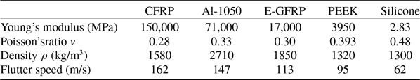
The influence of different honeycomb core materials on flutter speed was also investigated. In addition to PEEK and silicone, which were previously discussed, three additional materials commonly employed in flexible wing applications were considered for comparative analysis: carbon fiber reinforced polymer (CFRP) [Reference Katagiri, Yamaguchi, Kawakita, Honda, Sasaki, Kogiso and Tamayama37], Al 1050 alloy [Reference Emad, Mohamed and Fanni38] and elastomer-glass fiber reinforced polymer (E-GFRP) [Reference Mühlich, González, Born, Körner, Schwill, Gresser and Knippers39]. The analysis was conducted based on the butterfly honeycomb configuration with θ = −20° and t = 0.2 mm. As presented in Table 4, the results demonstrate a general positive correlation between flutter speed and the Young’s modulus of the core material. This trend can be attributed to the fact that materials with higher stiffness enhance the bending and torsional rigidity of the wingbox, thereby increasing its natural frequencies and requiring greater aerodynamic loading, in terms of flight speed, to induce flutter [Reference Wright and Cooper6]. Nevertheless, when considering the overall structural mass, PEEK emerges as a particularly suitable core material due to its relatively low density while still maintaining sufficiently high flutter resistance.
Material properties and corresponding flutter speeds for different core materials under butterfly honeycomb configuration (θ = −20°, t = 0.2 mm)

4.0 Baysian optimisation
In this study, the bayesopt function in Matlab is utilised to perform Bayesian optimisation on the internal cell angles θ and material thickness t of a CKW. The optimisation ranges are set from –40° ≤ θ ≤ 40° and 0.2 mm ≤ t ≤ 0.8 mm. The optimisation objectives include minimising mass, maximising flutter speed and minimising maximum displacement under aerodynamic conditions with an air density of 1.226 kg/m³, flight speed of 20 m/s and an angle-of-attack of 5°. In the objective function, the mass, flutter speed and maximum displacement of the wingbox are normalised, with each objective scaled such that the best value is normalised to 0 and the worst value to 1 using the following equation:
 \begin{align}N = \frac{{X - {X_{{\rm{best}}}}}}{{{X_{{\rm{worst}}}} - {X_{{\rm{best}}}}}} \end{align}
Where, $N$
represents each normalised value,
$N$
represents each normalised value, $X$
denotes a computed value within the initial dataset as shown in Figs 7, 8 and 10,
$X$
denotes a computed value within the initial dataset as shown in Figs 7, 8 and 10, ${X_{{\rm{best}}}}$
indicates the best value among the initial dataset, and
${X_{{\rm{best}}}}$
indicates the best value among the initial dataset, and ${X_{{\rm{worst}}}}$
signifies the worst value. The Bayesian optimisation objective function
${X_{{\rm{worst}}}}$
signifies the worst value. The Bayesian optimisation objective function $f\left( {\theta ,\,t} \right)$
is presented as follow:
$f\left( {\theta ,\,t} \right)$
is presented as follow:
 \begin{align}f\left( {\theta ,t} \right) = m \cdot {N_m} + f \cdot {N_f} + d \cdot {N_d} \end{align}
Results of the Bayesian optimisation objective function model after 60 evaluations for different ${\rm{m}}:{\rm{\;f}}:{\rm{\;d}}$
: (a) 1: 1: 1, (b) 3: 1: 1, (c) 1: 3: 1, (d) 1: 1: 3.
${\rm{m}}:{\rm{\;f}}:{\rm{\;d}}$
: (a) 1: 1: 1, (b) 3: 1: 1, (c) 1: 3: 1, (d) 1: 1: 3.

Where, ${N_m}$
,
${N_m}$
, ${N_f}$
, and
${N_f}$
, and ${N_d}$
represent the normalised values for the wingbox mass, flutter speed and maximum displacement, respectively.
${N_d}$
represent the normalised values for the wingbox mass, flutter speed and maximum displacement, respectively. $m$
,
$m$
, $f$
and
$f$
and $d$
are the weights for the respective optimisation objectives. To investigate the impact of prioritising different design objectives on optimisation outcomes, the weights for
$d$
are the weights for the respective optimisation objectives. To investigate the impact of prioritising different design objectives on optimisation outcomes, the weights for $m$
,
$m$
, $f$
and
$f$
and $d$
are considered in four distinct allocations: 1: 1: 1, 3: 1: 1, 1: 3: 1 and 1: 1: 3.
$d$
are considered in four distinct allocations: 1: 1: 1, 3: 1: 1, 1: 3: 1 and 1: 1: 3.
The results of the Bayesian optimisation objective function model after 60 evaluations are shown in Fig. 10, which effectively illustrates the shape of the predicted objective function under different weights and indicates the predicted point of the minimum value. Results of the objective values converge with the number of evaluations are shown in Fig. 11. The estimated minimum values stabilise after approximately 10 evaluations. The estimated optimal minimum of $m:\;f:\;d\;$
= 1: 1: 1 and 1: 1: 3 is located at t = 0.8 mm and θ = 40°, with
$m:\;f:\;d\;$
= 1: 1: 1 and 1: 1: 3 is located at t = 0.8 mm and θ = 40°, with $\;f\left( {\theta ,t} \right)$
= 0.839 and 0.887. The estimated optimal minimum of
$\;f\left( {\theta ,t} \right)$
= 0.839 and 0.887. The estimated optimal minimum of $m:\;f:\;d\;$
= 3: 1: 1 is located at t = 0.2 mm and θ = 40°, with
$m:\;f:\;d\;$
= 3: 1: 1 is located at t = 0.2 mm and θ = 40°, with $f\left( {\theta ,t} \right)$
= 1.161. The estimated optimal minimum of
$f\left( {\theta ,t} \right)$
= 1.161. The estimated optimal minimum of $m:\;f:\;d\;$
= 1: 3: 1 is located at t = 0.8 mm and θ = –40°, with
$m:\;f:\;d\;$
= 1: 3: 1 is located at t = 0.8 mm and θ = –40°, with $f\left( {\theta ,t} \right)$
= 1.278. Under varying priority objective weights, different optimal design parameters emerge. These optimisation results converge at the endpoints of the optimisation range, indicating that the best solutions are constrained by the boundaries of the optimisation space. Figure 12 displays Pareto points for multi-objective optimisation, showcasing the optimal design solutions within the optimisation range under different objective weights.
$f\left( {\theta ,t} \right)$
= 1.278. Under varying priority objective weights, different optimal design parameters emerge. These optimisation results converge at the endpoints of the optimisation range, indicating that the best solutions are constrained by the boundaries of the optimisation space. Figure 12 displays Pareto points for multi-objective optimisation, showcasing the optimal design solutions within the optimisation range under different objective weights.
Results of the objective values converge with the number of evaluations for different ${\rm{m}}:{\rm{\;f}}:{\rm{\;d}}:$
(a) 1: 1: 1, (b) 3: 1: 1, (c) 1: 3: 1, (d) 1: 1: 3.
${\rm{m}}:{\rm{\;f}}:{\rm{\;d}}:$
(a) 1: 1: 1, (b) 3: 1: 1, (c) 1: 3: 1, (d) 1: 1: 3.

Pareto points of initial dataset and optimised best points under different objective weights.

Given that the minimum flutter speed in the initial dataset is 65 m/s, which is substantially higher than the typical maximum flight speed of micro-UAVs, a flutter speed of 65 m/s is deemed to provide adequate safety margins. Therefore, within the optimisation ranges, the flutter speed is consistently within acceptable limits and is no longer considered in the optimisation objectives. The new Bayesian optimisation objective function is defined as $\left( {\theta ,t} \right) = {N_m} + {N_d}$
, considering only the impact of wingbox mass and maximum displacement. The results of this optimisation objective function model after 60 evaluations, and the convergence of objective values with the number of evaluations, are shown in Fig. 13. The estimated minimum values stabilise after 26 evaluations. The estimated optimal minimum is located at t = 0.313 mm and θ = 20.1°, with
$\left( {\theta ,t} \right) = {N_m} + {N_d}$
, considering only the impact of wingbox mass and maximum displacement. The results of this optimisation objective function model after 60 evaluations, and the convergence of objective values with the number of evaluations, are shown in Fig. 13. The estimated minimum values stabilise after 26 evaluations. The estimated optimal minimum is located at t = 0.313 mm and θ = 20.1°, with $f\left( {\theta ,t} \right)$
= 0.341. This represents a predicted best point that is distinct from any initial data point and does not reside at the edge of the optimisation ranges. New simulation for a wingbox model at t = 0.31 mm and θ = 20° yields a mass of 0.0706 kg and a maximum displacement of 1.57 mm. The corresponding normalised values are 0.105 for mass and 0.224 for maximum displacement, with an objective function value of 0.329. The Pareto points for mass and maximum displacement are displayed in Fig. 14. The optimised best point is located on the Pareto Front and is closer to the origin than all initial data points. The best objective function value in the initial dataset is located at t = 0.4 mm and θ = 20°, with a value of 0.335. After Bayesian optimisation, the new best objective function value is 0.329, an improvement of approximately 1.8%. When considering a scenario closer to reality, without the influence of sufficiently high flutter speeds, Bayesian optimisation effectively improves the design parameters of the CKW, making t = 0.31 mm and θ = 20° the new optimal design parameters.
$f\left( {\theta ,t} \right)$
= 0.341. This represents a predicted best point that is distinct from any initial data point and does not reside at the edge of the optimisation ranges. New simulation for a wingbox model at t = 0.31 mm and θ = 20° yields a mass of 0.0706 kg and a maximum displacement of 1.57 mm. The corresponding normalised values are 0.105 for mass and 0.224 for maximum displacement, with an objective function value of 0.329. The Pareto points for mass and maximum displacement are displayed in Fig. 14. The optimised best point is located on the Pareto Front and is closer to the origin than all initial data points. The best objective function value in the initial dataset is located at t = 0.4 mm and θ = 20°, with a value of 0.335. After Bayesian optimisation, the new best objective function value is 0.329, an improvement of approximately 1.8%. When considering a scenario closer to reality, without the influence of sufficiently high flutter speeds, Bayesian optimisation effectively improves the design parameters of the CKW, making t = 0.31 mm and θ = 20° the new optimal design parameters.
Results of (a) Bayesian optimisation objective function $f\left( {\theta ,t} \right) = {N_m} + {N_d}$
model after 60 evaluations and (b) objective values converge with the number of evaluations. The minimum value is 0.341 at t = 0.313 mm and θ = 20.1°.
$f\left( {\theta ,t} \right) = {N_m} + {N_d}$
model after 60 evaluations and (b) objective values converge with the number of evaluations. The minimum value is 0.341 at t = 0.313 mm and θ = 20.1°.

Pareto points and optimised best point of the Bayesian optimisation objective function $f\left( {\theta ,t} \right) = {N_m} + {N_d}$
.
$f\left( {\theta ,t} \right) = {N_m} + {N_d}$
.

5.0 Conclusion
This study advances the aeroelastic analysis and optimisation of CKW structures. Through finite element modeling and extensive numerical evaluations, it highlights the effects of internal cell angles θ and material thickness t on the aeroelastic properties of CKW for micro-UAV applications. The mass of the wingbox significantly decreases with increasing θ. The deformation resistance of the wingbox increases with t but varies non-monotonically with θ; the rectangular honeycomb configuration exhibits the least deformation resistance, while the hexagonal honeycomb configuration at θ = 20° shows the strongest. In terms of flutter speed for the wingbox, the performance of the butterfly honeycomb configuration is slightly better than that of the hexagonal honeycomb configuration and significantly superior to the rectangular honeycomb configuration.
Building on this, the study effectively employed Bayesian optimisation to search for optimal design parameters aimed at balancing minimising mass, minimising deformation, and maximising flutter speed. The results indicate that under different design objective weights, there are various optimal parameter configurations, allowing for customisation based on specific requirements. The study also conducted optimisation under the more realistic assumption that a flutter speed of 65 m/s is sufficiently safe, predicting optimal aeroelastic performance at t = 0.31 mm and θ = 20°. Finite element results align with this prediction, showing a performance improvement of approximately 1.8% over the best initial data.
This research demonstrates that CKW structures possess sufficient structural stability to maintain aerodynamic integrity under loading conditions, and that their favourable flutter characteristics may support high-speed or manoeuvering flight scenarios. Furthermore, the integration of Bayesian optimisation provides a practical framework for multi-objective optimisation in multidimensional design spaces for high-fidelity complex wingbox structures.
Acknowledgements
The authors would like to acknowledge the support from Computational Engineering Design Group at the University of Southampton.


 Open access