Nomenclature
- AAM
-
Advanced Air Mobility
- AARON
-
AeroAcoustic ROtor Noise
- AGL
-
above ground level
- ANOPP2
-
Aircraft NOise Prediction Program 2
- ATR
-
average temperature response
- CAMRAD
-
Comprehensive Analytical Model of Rotorcraft Aerodynamics and Dynamics
- CFD
-
computational fluid dynamic
- CFR
-
code of federal regulations
- CHARM
-
Comprehensive Hierarchical Aeromechanics Rotorcraft Model
- dB
-
decibel, unit of sound intensity
- DEP
-
distributed electric propulsion
- DGW
-
design gross weight
- DPFC
-
distributed propulsion and flight control
- DRB
-
disturbance rejection bandwidth
- EPNL
-
effective perceived noise level
- ETS
-
emissions trading scheme
- ESC
-
engine speed control
- FHA
-
functional hazard analysis
- FMECA
-
failure mode, effects, and criticality analysis
- FTA
-
fault tree analysis
- HECTR
-
high-efficiency civil tilt rotor
- ISA
-
international standard atmosphere
- MCP
-
maximum continuous power
- MRP
-
maximum rated power (typically 10 min)
- NASA
-
National Aeronautics and Space Administration
- NDARC
-
NASA Design and Analysis of Rotorcraft
- NOTAR
-
NO TAil Rotor
- ODM
-
on-demand mobility
- OEI
-
one engine inoperative
- OGE
-
out of ground effect
- QSMR
-
quiet single main rotor
- RCOTools
-
Rotorcraft Optimisation Tools
- RPM
-
revolutions per minute
- RVLT
-
Revolutionary Vertical Lift Technology
- SF
-
size factor
- TRL
-
technology readiness level
- UAM
-
Urban Air Mobility
- VTOL
-
vertical take-off and landing
- XDSM
-
eXtensible Design Structure Matrix
Symbols
- A
-
rotor disk area, $\pi$
R
2
$\pi$
R
2
- A blade
-
total blade planform area
- C
-
charge capacity
- C T
-
rotor thrust coefficient, T/
$\rho$
AV
tip
2
- C W
-
aircraft weight coefficient, W/
$\rho$
AV
tip
2
- D
-
rotor diameter, 2R; drag
- DL
-
disk loading, GW divided by total rotor disk area
- FM
-
aircraft or rotor figure of merit
- GW
-
gross weight (WO + payload + fuel)
- I
-
current, I = xC
- L
-
rotor lift
- L/D e
-
aircraft effective lift-to-drag ratio, WV/P
- L/D e
-
rotor effective lift-to-drag ratio, LV/(P o + P i )
- P
-
power
- P o
-
profile power
- P i
-
induced power
- R
-
rotor blade radius; range
- T
-
rotor thrust
- V
-
speed
- V be
-
best endurance speed (maximum 1/fuelflow)
- V br
-
best range speed (99% high side maximum V/fuelflow)
- V cruise
-
cruise speed
- V y
-
speed for best rate of climb
- V tip
-
rotor tip speed, ΩR
- V H
-
speed at maximum continuous power
- W
-
weight
- WE
-
aircraft empty weight
- WO
-
operating weight (WE + fixed useful load)
- x
-
current (capacity per hour)
-
$\rho$
-
air density
-
$\sigma$
-
rotor solidity, A blade /A
- Ω
-
rotor angular rotation speed


1.0 Introduction
There is a dream growing now in the aviation community of providing air mobility as an alternative for everyday transportation requirements, described variously as On Demand Mobility (ODM), Urban Air Mobility (UAM), Air Taxi Operations or Advanced Air Mobility (AAM).
The invention of a practical aircraft for vertical take-off and landing — the helicopter — was largely accomplished by the end of the 1940s. Invention required solving the problems of flight: effective control (including rotor collective and cyclic), lightweight power (eventually turboshaft engines) and efficient structures (beginning with articulated and teetering blades). After invention, development turned to dealing with stability, high vibration and excessive noise, and then decades have been devoted to finding an aircraft that will combine greater speed and cruise efficiency with good hover and VTOL capability. AAM operations in urban areas are generally acknowledged to require VTOL capability [Reference Dudley1–Reference Antcliff, Moore and Goodrich2], so achieving the dream will require new solutions to these old problems of rotorcraft, enabled by technology advances in noise, structures, automation and control, propulsion and energy generation-storage-utilisation, manufacturing and tools for VTOL aircraft design and analysis.
NASA is conducting research and investigations in Advanced Air Mobility (AAM) aircraft and operations. AAM missions are characterised by ranges below 300 nm, including rural and urban operations, passenger carrying as well as cargo delivery. Such vehicles will require increased automation and innovative propulsion systems, likely electric or hybrid-electric propulsion. Urban Air Mobility (UAM) is a subset of AAM and is the segment that is projected to have the most economic benefit and be the most difficult to develop. UAM requires an advanced urban-capable vehicle and an airspace system to handle high-density operations.
The NASA Revolutionary Vertical Lift Technology (RVLT) project is developing UAM VTOL aircraft designs [Reference Antcliff, Moore and Goodrich2–Reference Silva and Johnson10] that can be used to focus and guide research activities in support of aircraft development for emerging aviation markets. These NASA concept vehicles encompass relevant UAM features and technologies, including propulsion architectures (distributed electric, hybrid, turboshaft, diesel), highly efficient yet quiet rotors and aircraft aerodynamic performance and interactions. The configurations adopted are generic, intentionally different in appearance and design detail from prominent industry arrangements, while capturing many of the essential technology features. The purpose of the NASA concept vehicles is to provide specific configurations for communication of NASA’s Urban Air Mobility research, for support of design and analysis tool development, for technology trade studies and sizing excursions, and for modeling operational scenarios. These aircraft are common configurations for studies in acoustics, flight dynamics, propulsion safety and reliability, crashworthiness, and other disciplines, both within and external to NASA. Data on the NASA concept vehicles will be widely shared and fully documented; they have realistic performance and are based on a realistic set of design compromises. NASA has no plan to build or fly these concepts.
The NASA concept vehicles were developed in several phases: reduced-emission rotorcraft concepts [Reference Silva, Johnson and Solis3]; concept vehicles for operations at several aircraft sizes (number of passengers and range, [Reference Johnson, Silva and Solis4]); and vehicles for a UAM design mission [Reference Silva, Johnson, Antcliff and Patterson6, Reference Johnson8–Reference Whiteside, Pollard, Antcliff, Zawodny, Fei, Silva and Medina9]. The UAM design mission was identified as carrying six passengers over a 75 nm range (with 10 kt headwind), and 20 min cruise reserve [Reference Patterson, Antcliff and Kohlman5]. The principal concept vehicles developed for this mission are quadrotor, side-by-side helicopter, lift+cruise, single main rotor and tiltwing configurations. Additional concept vehicles are currently being examined, including a tiltrotor aircraft and a tilting-ducted-fan configuration. These UAM concept aircraft have been used already in numerous engineering investigations.
This paper summarises the results of these recent NASA investigations. The software tool suite used is outlined, and the concept aircraft developed are described. Observations about the design trade-offs and key design decisions are discussed. The viewpoint presented is that of the design group in the NASA RVLT project.
2.0 Design and analysis tools
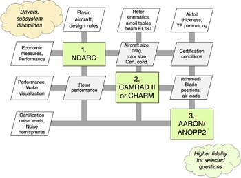
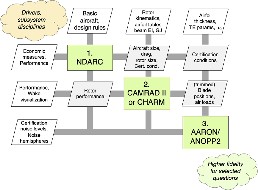
The process and tools for development of the NASA concept vehicles are described in Reference 10. Figure 1 illustrates the central tools in terms of an eXtensible Design Structure Matrix (XDSM) diagram. The primary tools for performing physical calculations are on the diagonal of the matrix as green rectangles, interconnections are grey lines and data entities are parallelograms. Data transfer and inter-tool design process are managed by scripts written in Python. The clouds at either end of the diagonal indicate that this toolchain can be integrated as part of a larger process. Overall inputs are in the white parallelograms at the top, and overall outputs are white parallelograms at the left. Guided design space exploration such as parameter sweeps, optimisation drivers, vehicle type comparison may be implemented in the upper-left, orange-coloured cloud, along with other subsystem design (e.g. propulsion, flight control). On the lower-right, the green-coloured cloud indicates where vehicle and subsystem design of higher fidelity would be added in order to verify earlier conceptual design assumptions, or capture phenomena that are inadequately addressed in earlier steps of the conceptual design process (e.g. a set of coupled CFD download and aerodynamic interaction calculations for key sizing conditions).
Diagram of the tools and workflow as the central part of a conceptual design process.
2.1 NDARC
Primary sizing and performance analysis of the aircraft is performed by NASA Design and Analysis of Rotorcraft (NDARC, [Reference Johnson11–Reference Johnson12]). NDARC has a modular architecture, facilitating its application to new aircraft and propulsion types, including non-traditional propulsion systems. Aircraft are represented as a collection of components, with surrogate or semi-analytic models for performance and weight of each component. NDARC performs fixed-point iteration to find the vehicle size based on specified sizing rules, missions and flight conditions. The most complete description of the concept aircraft is encapsulated in NDARC output files. NDARC is capable of assessing the impact of advanced technology and design choices. NDARC calculates economic measures, such as productivity, flyaway cost and operating cost for the concept aircraft. For a sized aircraft, NDARC calculates the weights and speeds to fly the required operations, such as noise metric conditions, as these are vehicle-specific, and must consider nonlinearities and limits in the propulsion system, not just aerodynamic performance. Advanced technology is incorporated in NDARC models in terms of the surrogate models for rotor and engine/motor performance, battery weight and efficiency and technology factors for component weights. Often useful aircraft technologies (such as active flow control) must be integrated into the design, accounting for weight and power increments as well as performance and efficiency improvements.
2.2 CAMRAD II or CHARM
A comprehensive analysis code simultaneously solves the rotor dynamics and aerodynamics for a trimmed or transient flight condition. CAMRAD II was used in the optimisation of the rotor geometry for the aircraft sizing conditions, and to develop calibrated rotor performance models for NDARC; as well as to calculate rotor and hub loads for structural design, assess rotor and blade stability and whirl flutter, and provide rotor blade airloads for mid-fidelity acoustics calculations. NASA is not actively developing its own comprehensive analysis solution, rather is applying commercial software for this step in the process. Two commercial codes, CAMRAD II [Reference Johnson13–Reference Johnson14] and CHARM [Reference Wachspress, Quackenbush and Boschitsch15], are being integrated interchangeably into the toolchain. By using two codes, a robust application programming interface can be defined that will allow other comprehensive analysis codes to be integrated into the toolchain. Both CAMRAD II and CHARM have well-validated free wake modeling capability. For interacting rotors, a freely convecting wake is necessary to accurately predict performance, as well as blade-vortex-interaction airloads that are responsible for significant noise. For example, lift+cruise, quadrotor, and side-by-side aircraft have rotors that interact to varying degrees in various stages of flight. Similarly, for practical UAM rotors larger than a couple of feet in radius, elastic and kinematic motion should be considered to calculate the rotor trim and blade-vortex interactions. Blade airloads and velocities will in general depend on blade motion, induced velocity, and wake convection. Whether or not the aerodynamic model of a comprehensive analysis code is adequate for evaluating the noise sources, a comprehensive analysis model of the structure is required. Building a comprehensive analysis model is generally a necessary step in the development of a meaningful high-fidelity simulation, as vehicle trim, rotor trim and blade kinematic and elastic motion are usually computed by a comprehensive analysis, which is coupled to CFD airloads.
2.3 AARON/ANOPP2
In order to predict the acoustic metrics, a tool that predicts thickness, loading, and broadband noise, acoustic propagation and observer noise is necessary. The Aircraft NOise Prediction Program 2 (ANOPP2, [Reference Lopes and Burley16–Reference Brooks, Pope and Marcolini18]) and AeroAcoustic ROtor Noise (AARON) tools provide the acoustic calculations in the toolchain. AARON is the user code to perform rotorcraft calculations with ANOPP2. A Python script provides a simplified interface that is geared toward generating the certification noise and other typical rotorcraft calculations with a manageably small number of inputs. AARON/ANOPP2 calculates the loading noise with a compact loading model, using the blade section loading and motion as well as the aircraft operating condition from the comprehensive analysis. Consistently, thickness noise is calculated with a compact monopole model. An aerofoil self-noise model extended to rotating blades is used for broadband noise [Reference Brooks, Pope and Marcolini18]. AARON/ANOPP2 can also calculate the loading and rotational noise from a higher-fidelity solution for the blade surface pressures and geometry, such as from CFD calculations.
2.4 RCOTools
Rotorcraft Optimisation Tools (RCOTools, [Reference Meyn19]) is a set of Python libraries that serve as application wrappers for input/output and program execution of several tools. In this toolchain, RCOTools interfaces for NDARC and CAMRAD II/CHARM are used. The data connections depicted by grey lines in the XDSM diagrams of Fig. 1 are facilitated by RCOTools.
2.5 Additional tools
Other tools are available to provide detailed models and data for the principal codes: engine models (NPSS [Reference Snyder and Tong20]); handling qualities assessment (SIMPLI-FLYD [Reference Lawrence, Theodore, Johnson and Berger21]; and FlightCODE); structural design and analysis (IXGEN [Reference Rohl, Dorman, Cesnik and Kumar22] and M4 Structures Studio [Reference Winter, Márquez and Scheneman23]); geometry and layout (OpenVSP [Reference Hahn24] for initial geometry; Rhino for final geometry); and high-fidelity aerodynamic loading (OVERFLOW [Reference Derlaga, Jackson and Buning25] and FUN3D [Reference Biedron, Carlson, Derlaga, Gnoffo, Hammond, Jacobson, Jones, Kleb, Lee-Rausch, Nielsen, Park, Rumsey, Thomas, Thompson, Walden, Wang and Wood26]).
2.6 Assessment of tools
A goal of the present tool suite development effort within NASA’s RVLT project is to provide robust computational methods that facilitate design space exploration with varied problem definitions and with the ability to concurrently consider several different potential solutions. The development of the NASA concept vehicles has demonstrated that the computational tools available for rotorcraft aeromechanics analysis and design are generally applicable to VTOL AAM aircraft. In particular, the toolchain has been capable of quantitatively trading several relevant noise reduction technologies and design approaches for aircraft that can perform the Urban Air Mobility mission [Reference Silva and Johnson10]. The calculations performed for these trades are quick enough to allow several simultaneous aircraft types to be evaluated by an individual designer or design team, with the calculations performed on workstation computers. The tools are practical, in terms of the amount of input required and the computation times [Reference Silva and Johnson10].
3.0 Reduced-emission rotorcraft concepts
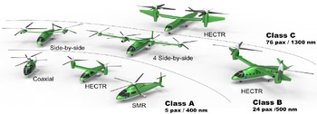
A prelude to the design of aircraft for UAM missions was an investigation of VTOL aircraft optimised for reduced emissions and acoustics [Reference Silva, Johnson and Solis3]. Rotorcraft concepts were developed with the goal of producing less than 50% of the climate-impacting emissions of today’s fielded technology. NDARC has two models for emissions [Reference Johnson11]: the emissions trading scheme (ETS) of the European Union, which accounts for CO2 only (the metric is kg CO2 per mission); and the average temperature response (ATR), which captures long-time integrated effects of CO2, H2O, NOx, O3, CH4, SO4, soot and aviation induced cloudiness (the metric is nano-°C of warming per mission). For electric propulsion, the ETS method includes the CO2 produced in generating the energy. For turboshaft propulsion, the ATR method uses an engine NOx emission model.
Reduced-emission rotorcraft concepts were developed for three aircraft size classes:
-
a) Class A: 5 passengers plus pilot, 400 nm range; baseline single main rotor and tail rotor helicopter;
-
b) Class B: 24 passengers plus 3 crew, 500 nm range; baseline single main rotor and tail rotor helicopter;
-
c) Class C: 76 passengers plus 5 crew, 1,300 nm range; baseline conventional tiltrotor.
The baseline aircraft represent today’s technology (TRL 9): un-faired hubs and aluminium structure for helicopters; fly-by-wire and fastened composites for tiltrotors; current technology turboshaft engines; crashworthy structures; and inclement weather operation.
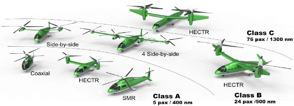
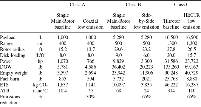
Figure 2 shows the reduced-emission rotorcraft designs. The principal characteristics of the baseline and reduced-emission designs are given in Table 1. While several advanced aircraft types were considered (Fig. 2), Table 1 only presents the baseline and the best (lowest-emission) designs for each class. Advanced technologies (TRL 5+) considered include more attention to drag (faired hubs, landing gear), more composite structures (bonded instead of fastened), advanced drive systems materials and approaches, and advanced turboshafts for classes B and C. These technologies alone could not make the helicopters clean enough, with only about 20% reduction in emissions for class A, and 35%–40% reduction for classes B and C. Considering more efficient aircraft types was necessary: coaxial helicopters, side-by-side helicopters and high-efficiency civil tiltrotors (HECTR). The HECTR design for class C achieved 70% reduction of emissions. The side-by-side helicopter (2 or 4 rotors) and the HECTR achieved 65% reduction of emissions for class B. The lack of an efficient small (<1,000 shp) turboshaft development meant that turboshaft-power designs for class A did not achieve the goal of 50% reduction: only achieved 20% reduction of emissions for the single main-rotor and tail-rotor helicopter, 30% reduction for the coaxial helicopter or tiltrotor (the tiltrotor does not get light enough to take advantage of its cruise efficiency).
Reduced-emission rotorcraft concepts: environmentally friendly aircraft designs [Reference Silva, Johnson and Solis3].
Characteristics of reduced-emissions aircraft [Reference Silva, Johnson and Solis3]
Electrical propulsion concepts were examined for the smaller classes, considering very long-term goals for weights and efficiencies (currently below TRL 2). Battery-powered aircraft do not meet the goal, since besides increasing the vehicle weight, U.S. electric grid emissions are high. Emissions from fuel cells can be very low, even if the hydrogen is obtained from a methane source, although the weights are high.
This work on low-emission rotorcraft provided the foundation for exploring UAM designs: development of an integrated tool suite for the multidisciplinary design and optimisation of VTOL aircraft; demonstration of alternative propulsion architectures in NDARC, including electric power; and quantification of the cruise efficiency of the side-by-side helicopter type.
4.0 Concept vehicles for air taxi operations
To begin the process of developing concept vehicles for air taxi operations, the range of aircraft attributes being considered by the design community was examined:
-
a) number of occupants (including pilot): 1, 2, 4, 6, 15, 30
-
b) un-refueled range: 50, 100, 200, 400, 800 nm (as multiples of 50 nm segments for this investigation)
-
c) market: air taxis, commuter scheduled, mass transit, airline
-
d) aircraft type: multicopter, side-by-side, tiltwing, tiltrotor, lift+cruise, vectored thrust, compound, helicopter
-
e) propulsion system: turboshaft, turbo-electric, electric, parallel hybrid, fuel cell, diesel
NASA developed three concept vehicles ([Reference Johnson, Silva and Solis4], Fig. 3) that encompass many elements of this design space:
-
1) A single-passenger (250-lb payload), 50-nm range quadrotor with electric propulsion (with inter-connect shaft between rotors), using flapping rotors and collective control; design excursions included rigid rotors, rotor speed control (fixed pitch blades) and reciprocating engines.
-
2) A six-passenger (1,200-lb payload), 200-nm range (four 50-nm trips) side-by-side helicopter with hybrid propulsion; excursions included turboshaft and electric propulsion.
-
3) A 15-passenger (3,000-lb payload), 400-nm range (eight 50-nm trips) tiltwing with turbo-electric propulsion, using four propellers with collective and cyclic control; design excursions included tail propellers for pitch and directional control.
Concept aircraft: single-passenger quadrotor with electric propulsion, 15-passenger tiltwing with turboelectric propulsion, and 6-passenger side-by-side helicopter with hybrid [Reference Johnson, Silva and Solis4].
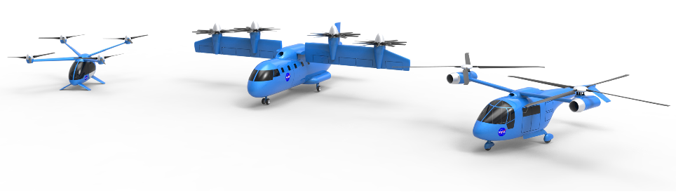
The principal characteristics of these concept aircraft are given in Table 2.
Characteristics of concept aircraft for initial air taxi mission [Reference Johnson, Silva and Solis4]
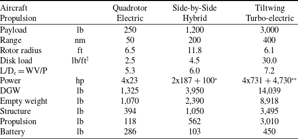
*turboshaft & motor **motor & turboshaft
The primary sizing mission consists of the following segments: (1) 2-min hover out-of-ground-effect (OGE) for takeoff; (2) fly 50 nm at best-range speed; (3) 2-min hover OGE for landing; (4) fuel/energy reserve minimum of 10% of mission or 20-min flight at best-endurance speed ( ${V_{be}}$
). All the segments are flown at atmospheric conditions of 5,000-ft altitude and ISA + 20°C temperature. Segments 1–3 are repeated for each 50 nm leg in the un-refueled range. Cruise is flown at best-range speed (
${V_{be}}$
). All the segments are flown at atmospheric conditions of 5,000-ft altitude and ISA + 20°C temperature. Segments 1–3 are repeated for each 50 nm leg in the un-refueled range. Cruise is flown at best-range speed ( ${V_{br}}$
, 99% high side), unless the maximum speed is less than
${V_{br}}$
, 99% high side), unless the maximum speed is less than ${V_{br}}$
. Reserve requirements are based on 14 CFR 91.151: 20-min at cruise speed for visual flight rules (VFR) rotorcraft. A second sizing mission has these segments flown at sea level and ISA + 20°C temperature.
${V_{br}}$
. Reserve requirements are based on 14 CFR 91.151: 20-min at cruise speed for visual flight rules (VFR) rotorcraft. A second sizing mission has these segments flown at sea level and ISA + 20°C temperature.
All-weather operations are assumed, which has an impact on systems weight (including de-icing). For low aircraft noise, the design rotor tip speed is low compared to conventional helicopters: 450 ft/sec for the quadrotor, 550 ft/sec for the larger aircraft. (In general, reducing the design hover tip speed increases the size of the aircraft; the consequences of weight growth are less for a small aircraft, so a lower tip speed can be used for the quadrotor.) Maximum speed (from power available at 90% MCP) is fallout (not specified), with installed power determined by takeoff conditions.
4.1 Battery technology
Light and efficient batteries are crucial to producing good designs for electric aircraft. The electric designs for these aircraft assume an installed, usable battery specific energy of 400 Wh/kg (pack). Internal resistance reduces battery efficiency at high discharge rates, so typical Li-ion battery discharge characteristics are used to calculate the efficiency. Margins for maximum charge and discharge are established to prolong battery life (in terms of discharge-charge cycles): charge to within 5%–10% of full capacity, discharge to 15%–20% capacity. Current delivery limits for cells are specified as a C-rate (capacity/hr). Even with a high maximum burst discharge capability (high maximum power), discharge currents in today’s high-specific-energy Li-ion cells must be limited to 2–3C for good battery life. The installed specific energy is reduced by packaging and conditioning requirements, including thermal management systems. For the electric propulsion variants of the three configurations, design excursions of range and battery technology were generated to quantify the impact on aircraft weight, power, and feasibility. Specific weight, the crucial aspect of battery technology for aircraft design, was considered from 400 Wh/kg down to 150 Wh/kg (values for pack, not cell). Below about 300 Wh/kg, the range capability was reduced while the aircraft weight increased. Having established these trends, a high level of battery technology had to be assumed for the UAM concept vehicles to ensure that the designs would meet the mission requirements.
5.0 Vehicles for the UAM mission
Following the initial air taxi vehicle study, which explored vehicle technology themes using aircraft of various sizes designed for several candidate missions, RVLT performed a focused study to better understand a particular urban air mobility market. A design mission was developed accounting for the existing geography, population patterns, infrastructure and weather in 28 markets across the United States [Reference Patterson, Antcliff and Kohlman5]. The resulting mission is to carry six passengers (including the pilot, if not autonomous; 1,200 lb payload) on two 37.5-nm flights (total 75-nm range without recharging or refueling), with a 20 min reserve (Fig. 4). Takeoff altitude is 6,000-ft (ISA), and cruise is at best range speed, 4,000-ft above ground level (AGL). This mission is intended to be used as a sizing requirement. The actual operational missions flown by the aircraft will be different, driven by economics, air traffic, and other aspects of a particular flight.
UAM sizing mission profile [Reference Patterson, Antcliff and Kohlman5].

In order to quantify the tradeoffs and performance targets necessary for practical implementation of the UAM vision, NASA concept vehicles were designed to perform this mission [Reference Silva, Johnson, Antcliff and Patterson6, Reference Johnson8–Reference Whiteside, Pollard, Antcliff, Zawodny, Fei, Silva and Medina9]. A range of aircraft types and propulsion system architectures were considered (Fig. 5): quadrotor aircraft, with turboshaft and electric propulsion; side-by-side aircraft, with turboshaft and electric propulsion; lift+cruise aircraft with electric and turbo-electric propulsion; a quiet single-main rotor helicopter with turboshaft and electric propulsion; and a tiltwing aircraft with turbo-electric propulsion.
UAM aircraft designs: six occupants (1,200 lb), 75 nm range [Reference Silva, Johnson, Antcliff and Patterson6, Reference Johnson8–Reference Whiteside, Pollard, Antcliff, Zawodny, Fei, Silva and Medina9].
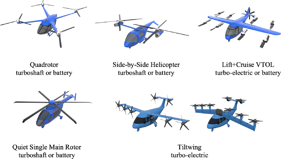
Certain technologies and attributes that are expected to be included in a new-start aircraft have been included in the models for all of the concept vehicles. These features include muffling of the engine and drive system to reduce noise to a level lower than that of the rotor system, with associated weight and performance penalties. Systems weights include instrumented flight rules-capable avionics, cockpit controls, and fly-by-wire flight controls; these weights serve as the initial budget for an autonomous flight control system. Vibration mitigation weights have been included for each of the aircraft. Furnishings weights include crashworthy seats, sound dampening, and environmental control systems. The airframe and rotor structures use technology factors calibrated to composite rotorcraft with crashworthiness considerations. The turboshaft engines represent state-of-the-art turboshafts, which at this scale are relatively fuel-thirsty and have not had much technology insertion for many decades. Further discussion of technologies for the concept aircraft may be found in [Reference Antcliff, Whiteside, Silva and Kohlman7].
Consistent technology assumptions were made to size the vehicles:
-
a) Battery pack modeled as Li-Ion (TRL 1): installed, usable specific energy 400 Wh/kg (well beyond state-of-the-art); maximum mission current 4C, emergency 14C (high end state-of-the-art); wiring and accessory electric systems as fractions of motor weight (TRL 3)
-
b) Structures (TRL 3+): composite VTOL structures, very lightweight booms
-
c) Aerodynamics (TRL 5+): passive rotor and airframe lift/drag
-
d) Propulsion (TRL 5+): high torque/weight electric motors; high torque/weight transmissions
-
e) Systems (TRL 5+): equipment for instrument flight rules (IFR) operations (hence autonomy possible without additional weight); environmental control systems, insulation, seating
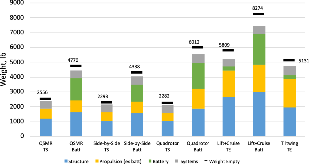
All aircraft (five aircraft types so far, two propulsion architectures for most, plus numerous excursions) were designed to the same mission. The principal characteristics of the designs are given in Table 3. Figure 6 shows the breakdown of the weight empty. For each design, the payload is 1,200 lb and the fuel for turboshaft propulsion is 150–180 lb. Generally, structural and propulsion weights increase with the number of rotors. There is only one design mission, so the battery capacity equals the energy (including reserve) needed for that mission. Even high specific-energy batteries are heavy, so all-electric propulsion produces a heavier aircraft than turboshaft or hybrid or turbo-electric propulsion. The high cruise efficiency of the lift+cruise type reduces the battery weight compared to the quadrotor, but not enough to counter the increase in structure and propulsion weight, so the all-electric lift+cruise aircraft is the heaviest design.
Characteristics of UAM concept vehicles [Reference Silva, Johnson, Antcliff and Patterson6, Reference Johnson8–Reference Whiteside, Pollard, Antcliff, Zawodny, Fei, Silva and Medina9]
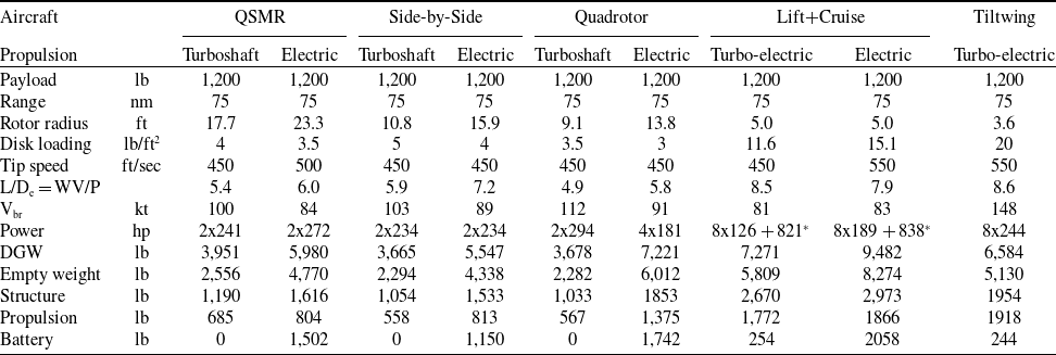
*lift motors + cruise motor
Structure, propulsion and systems components of empty weight (weight empty = structure + propulsion + systems + vibration control + contingency; TS = turboshaft, TE = turbo-electric).
5.1 Quiet Single Main Rotor Helicopter
The Quiet Single Main Rotor helicopter (QSMR) is representative of a state-of-the-art helicopter designed specifically for the UAM mission [Reference Johnson8]. In addition to shorter range for UAM applications, several design decisions were made to bias the design toward low noise. The tools in the toolchain have been validated with legacy helicopters [Reference Johnson12–Reference Lopes and Burley16], including some helicopters with the noise reduction technologies employed in this demonstration. Therefore, the predicted size, weight, performance and noise of the QSMR is expected to be quite close to that of a real aircraft designed to these criteria and with the assumed level of technology. The relative predictions of the other vehicles can therefore be compared to the QSMR, in order to establish a reasonable expectation of the absolute merits and costs.
The impact of rotor noise on community acceptance of helicopters was recognised early, so there have been five decades of work on reducing noise. From the beginning, much of the focus was on the design variables of tip speed and tail rotor size. Based on demonstrated technology, the QSMR concept vehicle uses a turboshaft engine with a sound-absorbing installation (accounted for in weight of engine installation), and the NOTAR (NO TAil Rotor) anti-torque system to eliminate tail-rotor noise. The NOTAR system is heavier than a traditional tail rotor, but can reduce the anti-torque contribution to noise to such an extent that the main rotor is by far the dominant noise source. For low main rotor noise, the design has a low disk loading and low tip speed, hence large blade area and a large number of blades. The direct and indirect results of low tip speed include high rotor and transmission weight, which increases the aircraft takeoff weight. Design excursions include turboshaft and electric propulsion. The effects of blade tip droop and higher-harmonic control on the aircraft noise were examined [Reference Johnson8].
5.2 Quadrotor
The quadrotor aircraft is intended to represent multirotor-type aircraft, which use collective or rotor speed control for flight control, without cyclic control [Reference Silva, Johnson, Antcliff and Patterson6]. One interesting attribute of the designs for the NASA quadrotor concept aircraft is that the rear rotors are mounted higher on the aircraft than the forward rotors. Initial design work with the free wake comprehensive analysis in CAMRAD II led to this design decision, as a significant reduction in power required for cruise was predicted. Subsequent higher fidelity analysis confirmed the beneficial effect, albeit with a different absolute magnitude. Design excursions include turboshaft, hybrid and electric propulsion. The implications of hingeless blades, rpm control and reciprocating engine propulsion were examined for the single-passenger quadrotor [Reference Johnson, Silva and Solis4].
5.3 Side-by-side helicopter
The side-by-side helicopter [Reference Silva, Johnson and Solis3, Reference Antcliff, Whiteside, Silva and Kohlman7] is representative of a high-performance helicopter, which has main rotors that intentionally interact as they physically overlap and intermesh. The side-by-side aircraft has a support crossbar to support the rotors, but this bar does not generate significant lift. The interaction of the main rotors is intended to reduce induced power in forward flight. Design excursions include turboshaft, electric and hybrid propulsion.
5.4 Lift+Cruise aircraft
The Lift+Cruise aircraft [Reference Silva, Johnson, Antcliff and Patterson6] is a stopping-rotor thrust- and lift-compound helicopter. There are three distinct flight modes for the aircraft: helicopter mode with the lifting rotors turning, compound mode with lifting and thrusting rotors operating and airplane mode with the lifting rotors stopped and forward thrust is provided by a pusher propeller. In airplane mode, the lifting rotors are stopped with the blade axis pointed along the vehicle longitudinal axis, and therefore nominally aligned with the free stream to minimise drag. Unlike the other concept vehicles, the lift+cruise aircraft can only have two blades on the lifting rotors, so as the rotor speed and solidity changes, no change is allowed in number of blades. The vast majority of lift+cruise aircraft being proposed have fixed rotor pitch and use variable rpm for control. However, to facilitate calculations of aerodynamic interference and noise, investigations can model the aircraft using collective control of the lifting rotors with fixed (identical) rotational speed. Similar to the quadrotor, the lift+cruise aircraft has the rear rotors mounted higher than the front rotors. The performance effects are similar for rotor-rotor interference, but there are now two additional considerations: the influence of the boom for an under-mounted rotor and the interference with the wing. By placing the front rotor under the support boom, a simpler and more compact support can be built. Design excursions include turbo-electric and electric propulsion.
5.5 Tiltwing
The tiltwing vehicle [Reference Whiteside, Pollard, Antcliff, Zawodny, Fei, Silva and Medina9] uses a turbo-electric propulsion system to power six proprotors positioned on a tilting main wing and two tilting proprotors positioned on the horizontal tail. All rotors are directly connected to electric motors, with no interconnect shaft. There is a single turboshaft engine connected to a generator, with a relatively small battery just to enable emergency landing after loss of turboshaft power. Collective control is used, with hover tip speed of 550 ft/sec and cruise tip speed of 300 ft/sec. A tiltwing is of interest for UAM due to its potential to increase cruise speed and efficiency while reducing noise in cruise. The other concept vehicles all have rotors that do not tilt and so either operate in edgewise flight (which limits cruise speed and typically generates more noise than a proprotor in axial flight) or are stopped during cruise (generating drag and weight penalties).
All proprotors are located ahead of the wing leading edge by 3/4 the proprotor radius, in order to reduce the noise caused by wing-rotor interaction; however, this introduces additional challenges in structures (long moment arm) and aerodynamics (the contracted proprotor wake does not yield beneficial aero-propulsive effects along the full span of the wing). The main wing is swept so that the proprotors are longitudinally staggered to prevent cascading proprotor failures. Laterally, the main wing proprotors are placed such that the inboard proprotor is close to the fuselage and the proprotor disks are tangential to one another as viewed from the front. Although this will leave sections of the wing unblown as the slipstream aft of the proprotors contracts, the inflow to the proprotors will be cleaner and the reduced rotor-rotor interaction is expected to reduce noise and increase efficiency. The proprotors at wing tips are positioned such that the shaft axis is coincident with the wing tip to assist in counteracting the wing tip vortex.
6.0 Engineering observations
In examining the vehicles from this series of design investigations, performance targets and recurring technology themes emerged, which may guide investments in research. In addition, results from the various designs support observations about the trade-offs and key design decisions.
These UAM concept aircraft have been used in numerous engineering investigations [Reference Chapman27–Reference Justin, Patel, Bouchard, Gladin, Verberne, Li, Ozcan, Rajaram, Mavris, D’Arpino, Aldemir, Rizzoni, Türkmen, Mayo and Bivens85], including work on meeting safety requirements, achieving good handling qualities, and reducing noise below helicopter certification levels.
6.1 Battery technology
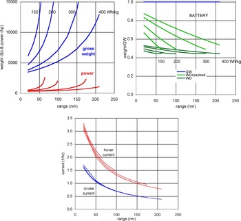
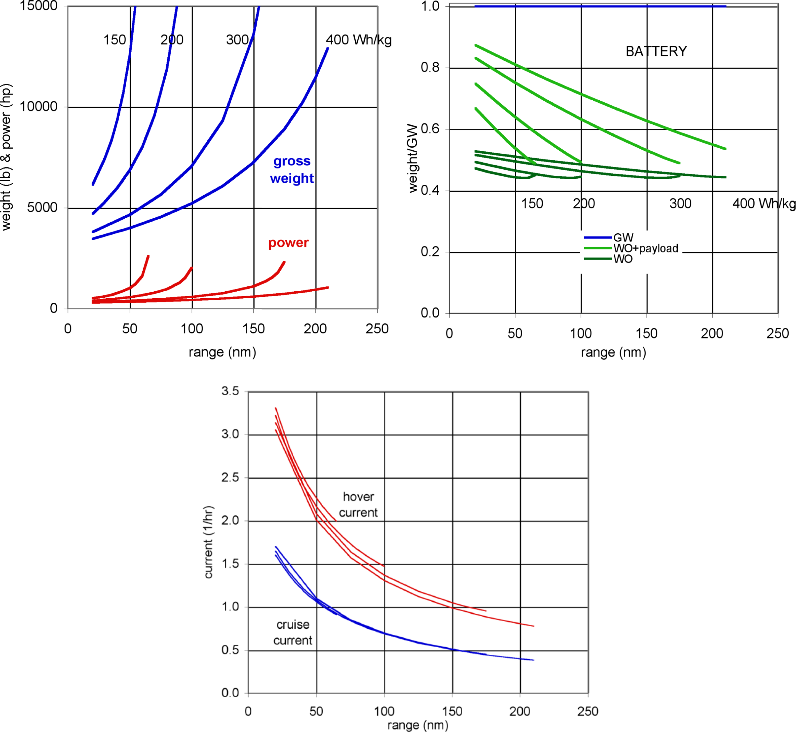
The most important factor in the feasibility of electrical propulsion systems is the requirement for light-weight, high-power batteries. The baseline designs here assume an installed, usable specific energy of 400 Wh/kg. Current state-of-the-art batteries have installed specific energy of 100–150 Wh/kg. The weight and power variation with range and battery technology are shown in Fig. 7 for an electric side-by-side aircraft. High specific energy enables a useful range with a reasonable aircraft weight and power. Aircraft size does not change the conclusions from these figures, as similar results are obtained for both single-passenger and 15-passenger side-by-side designs [Reference Johnson, Silva and Solis4].
Electric side-by-side helicopter (six passengers): weight and power variation with range and battery technology; discharge current for battery technology 150–400 Wh/kg (pack).
The power capability of batteries is also important. High power is obtained with high current, and current can be characterised by fraction x of the charge capacity $C$
:
$C$
: $I = xC$
, with units of 1/hr for
$I = xC$
, with units of 1/hr for $x$
. A maximum burst discharge current of 10
$x$
. A maximum burst discharge current of 10 $C$
to 30
$C$
to 30 $C$
(fully discharged in 6 to 2 minutes) is possible for emergency use, but long battery life typically requires currents of 1
$C$
(fully discharged in 6 to 2 minutes) is possible for emergency use, but long battery life typically requires currents of 1 $C$
to 3
$C$
to 3 $C$
. The discharge current variation with range is shown in Fig. 7 for the electric side-by-side aircraft. The cruise current is less than the hover current for these designs, since cruise speed is fallout (not specified) and the power is sized by the hover condition. The battery capacity is the sum of hover, cruise and reserve requirements:
$C$
. The discharge current variation with range is shown in Fig. 7 for the electric side-by-side aircraft. The cruise current is less than the hover current for these designs, since cruise speed is fallout (not specified) and the power is sized by the hover condition. The battery capacity is the sum of hover, cruise and reserve requirements:
 \begin{align} {E_{cap}} = {E_{cruise}} + {E_{hover}} + {E_{reserve}} \end{align}
Writing cruise power in terms of the aircraft effective lift-to-drag ratio ( ${P_c} = WV/\left( {L/{D_e}} \right)$
), the cruise energy is proportional to range:
${P_c} = WV/\left( {L/{D_e}} \right)$
), the cruise energy is proportional to range:
 \begin{align}{E_{cruise}} = \left( {{P_c}/{\eta _c}} \right) \times {\rm{time}} = WV \times {\rm{time}}/\left( {\left( {L/{D_e}} \right){\eta _c}} \right) = WR/\left( {\left( {L/{D_e}} \right){\eta _c}} \right)\end{align}
where ${\eta _c}$
is the propulsion system efficiency in cruise, and the range is
${\eta _c}$
is the propulsion system efficiency in cruise, and the range is $R = V \times {\rm{time}}$
. From the charge capacity
$R = V \times {\rm{time}}$
. From the charge capacity ${C_{cap}} = {E_{cap}}/\nu $
(for voltage
${C_{cap}} = {E_{cap}}/\nu $
(for voltage $\nu $
), and hover current
$\nu $
), and hover current $I = \left( {{P_h}/\nu } \right)/{\eta _h})$
(
$I = \left( {{P_h}/\nu } \right)/{\eta _h})$
( ${\eta _h}$
is the propulsion system efficiency in hover), the hover discharge current is
${\eta _h}$
is the propulsion system efficiency in hover), the hover discharge current is
 \begin{align}{x_{hover}} = I/{C_{cap}} = {P_h}/\left( {{\eta _h}{E_{cap}}} \right) = \left( {W\sqrt {W/2\rho A} /FM} \right)/\left( {{\eta _h}{E_{cap}}} \right)\end{align}
with hover power in terms of figure of merit ( ${P_h} = W\sqrt {W/2\rho A} /FM$
). Substituting for
${P_h} = W\sqrt {W/2\rho A} /FM$
). Substituting for ${E_{cap}}$
gives
${E_{cap}}$
gives
 \begin{align}1/{x_{hover}} = R\frac{{{\eta _h}FM}}{{{\eta _c}\left( {L/{D_e}} \right)}}/\sqrt {W/2\rho A} + {\rm{constant}}\end{align}
where the constant comes from the hover and reserve energy capacity. Ignoring the constant gives
 \begin{align}{x_{hover}} = \sqrt {W/2\rho A} \frac{{{\eta _c}\left( {L/{D_e}} \right)}}{{{\eta _h}FM}}\frac{1}{R}\end{align}
High hover efficiency (low disk loading and high figure of merit) reduces the current, but short range or high cruise efficiency $\left( {L/{D_e}} \right)$
reduces the battery capacity required, hence increases the hover current
$\left( {L/{D_e}} \right)$
reduces the battery capacity required, hence increases the hover current ${x_{hover}}$
. As illustrated in Fig. 7, this result is independent of battery technology, except as it impacts the range that is achievable by a design. For the side-by-side aircraft, the hover current
${x_{hover}}$
. As illustrated in Fig. 7, this result is independent of battery technology, except as it impacts the range that is achievable by a design. For the side-by-side aircraft, the hover current ${x_{hover}} \lt 1C$
if the range is greater than about 160 nm, and
${x_{hover}} \lt 1C$
if the range is greater than about 160 nm, and ${x_{hover}} \lt 2C$
if the range is greater than about 60 nm.
${x_{hover}} \lt 2C$
if the range is greater than about 60 nm.
The conclusion from Fig. 7 is that reasonable hover current requires that the aircraft have a large battery, preferably because of good weight efficiency permitting long range, not because of low cruise efficiency.
6.2 Aircraft aerodynamic efficiency
Electric propulsion is enabled by aerodynamic efficiency of the aircraft, in both hover and cruise. For each design, there is a disk loading that minimises aircraft weight, power, and energy. Small aircraft with edgewise rotors optimise with low disk loading. Rotor-rotor interference must be considered for optimum cruise performance. Interactional aerodynamics impact performance and operation: for tiltwings, wing separation or buffet during conversion must be considered; for tiltrotors, hover download and rotor-tail interactions must be considered. Rotor shape optimisation covers blade twist and taper, tip sweep and droop. Drag minimisation includes hub, rotor support and airframe.
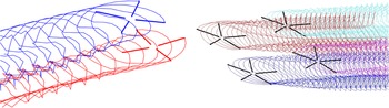
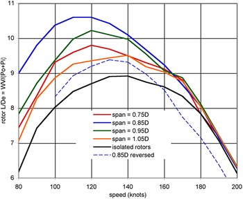
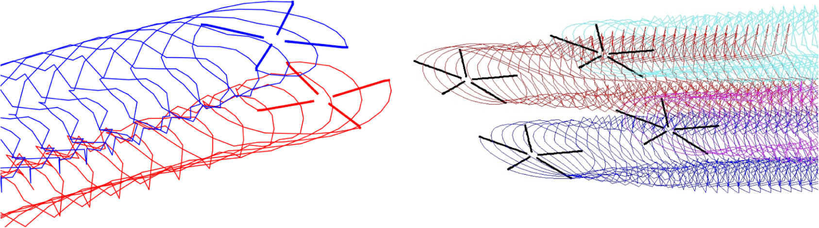
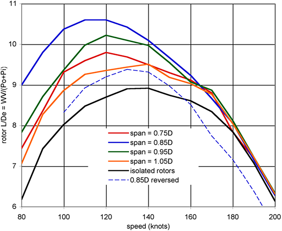
For aircraft with two or more main rotors, interactions between the rotors have a significant impact on performance, vibration, noise and handling qualities. The interactions depend on the arrangement of the rotors. Figure 8 illustrates the wake geometry of the quadrotor and side-by-side aircraft in cruise flight. The overlap of the side-by-side rotors significantly improves the efficiency of cruise flight, because the twin rotors act as a single, large-span wing system. Figure 9 (from [Reference Silva, Johnson, Antcliff and Patterson6]) shows the influence of overlap (wing span = 1.0D = rotor diameter means the rotor disks are tangent) on rotor efficiency (rotor $L/{D_e} = WV/\left( {{P_i} + {P_o}} \right)$
).
$L/{D_e} = WV/\left( {{P_i} + {P_o}} \right)$
).
Wake geometry of side-by-side and quadrotor aircraft at cruise speed.
Rotor cruise efficiency as function of overlap for side-by-side helicopter.
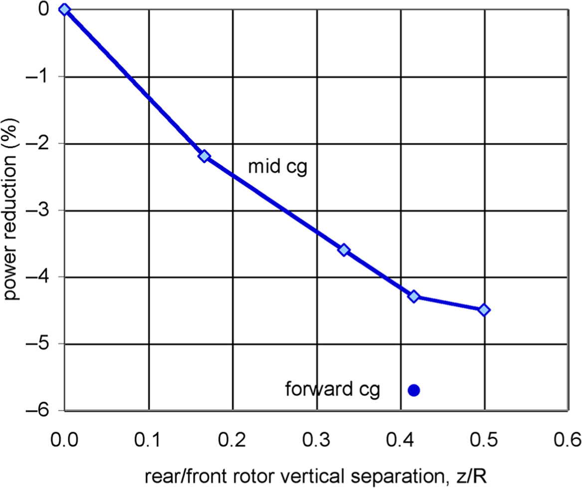
Elevating the rear rotors above the front rotors on the quadrotor reduces the cruise power, as shown in Fig. 10 (from [Reference Silva, Johnson and Solis3]), by reducing the interference of the wakes of the front rotors on the rear rotors. Elevating the rear rotors is expected to reduce vibration and noise and improve handling qualities as well. Moving the aircraft center of gravity forward of the mid-point between the rotors, so the front and rear rotors trim closer to the same blade loading CT/ $\sigma$
at cruise speed, further reduces the power (Fig. 10).
$\sigma$
at cruise speed, further reduces the power (Fig. 10).
Influence of elevation of rear rotors on cruise performance of quadrotor.
The effects of the rotor-rotor interactions may require vibration and load alleviation systems. The present designs have a weight allocation for vibration control.
6.3 Trim of multi-rotor aircraft
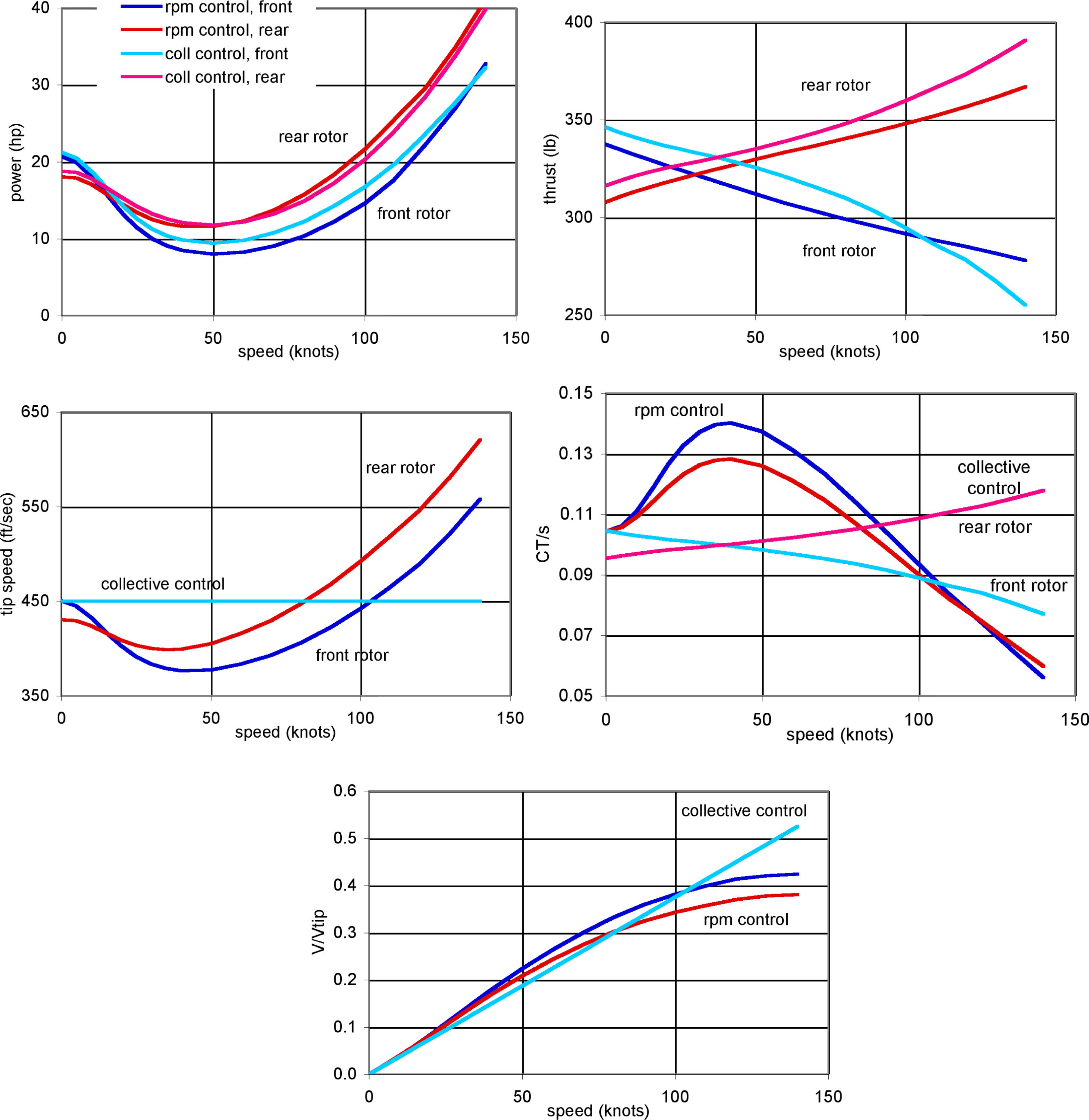
For the quadrotor, both collective and rotor speed control were considered. Figure 11 shows the trim operating conditions of the front and rear rotors for the two control methods. Edgewise rotor flight has reduced induced power (relative hover, for the same lift) due to increased flow through the disk, followed by power increasing with speed as the parasite power increases. The thrust of the rear rotors increases with speed relative the front rotors, for aircraft pitch moment trim. With collective control and fixed rotor speed, the rotor blade loading CT/ $\sigma$
follows the thrust variation, remaining moderate, while the collective control follows the power variation with speed. With rotor speed control and fixed collective, the rotor rpm follows the power variation with speed, while the rotor CT/
$\sigma$
follows the thrust variation, remaining moderate, while the collective control follows the power variation with speed. With rotor speed control and fixed collective, the rotor rpm follows the power variation with speed, while the rotor CT/ $\sigma$
increases with speed initially and then decreases (Fig. 11). The increase in CT/
$\sigma$
increases with speed initially and then decreases (Fig. 11). The increase in CT/ $\sigma$
might be limited by maximum blade loading, perhaps requiring a smaller design CT/
$\sigma$
might be limited by maximum blade loading, perhaps requiring a smaller design CT/ $\sigma$
at hover (hence larger blade area).
$\sigma$
at hover (hence larger blade area).
Electric quadrotor trim as a function of flight speed, for collective control and rotor speed control (with collective control, tip speed and V/Vtip are same for front and rear rotors).
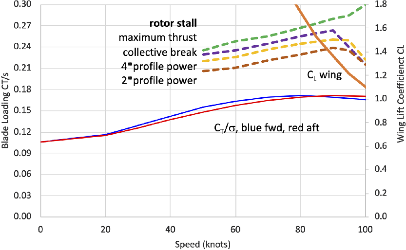
For the lift+cruise aircraft, Fig. 12 shows the variation with speed of the rotor blade loading CT/ $\sigma$
and wing lift coefficient. CL. This design has rigid rotors for hover and low speed lift, using fixed pitch and rotor speed control. The lift rotors are stopped for cruise, with the wing providing all lift. As the induced power decreases with speed, the rotor blade loading CT/
$\sigma$
and wing lift coefficient. CL. This design has rigid rotors for hover and low speed lift, using fixed pitch and rotor speed control. The lift rotors are stopped for cruise, with the wing providing all lift. As the induced power decreases with speed, the rotor blade loading CT/ $\sigma$
increases. As speed decreases, the wing lift coefficient increases, bringing the wing closer to stall. Figure 12 also shows the rotor loading limits due to stall, according to four measures: maximum thrust, change in thrust derivative with collective, four times the profile power and twice the profile power. These hingeless, fixed-pitch rotors operate with large hub roll moments in forward flight (here advance ratio 0.36 and lift offset 0.34 at 90 knots), which increases the loading limits due to stall (a flapping rotor has a steady stall limit of about CT/
$\sigma$
increases. As speed decreases, the wing lift coefficient increases, bringing the wing closer to stall. Figure 12 also shows the rotor loading limits due to stall, according to four measures: maximum thrust, change in thrust derivative with collective, four times the profile power and twice the profile power. These hingeless, fixed-pitch rotors operate with large hub roll moments in forward flight (here advance ratio 0.36 and lift offset 0.34 at 90 knots), which increases the loading limits due to stall (a flapping rotor has a steady stall limit of about CT/ $\sigma$
= 0.12 at 90 knots). At sufficiently high speeds (here above 90 knots), blade stall encompasses most of the rotor disk, and the CT/
$\sigma$
= 0.12 at 90 knots). At sufficiently high speeds (here above 90 knots), blade stall encompasses most of the rotor disk, and the CT/ $\sigma$
limit decreases. The design hover CT/
$\sigma$
limit decreases. The design hover CT/ $\sigma$
must be low enough and the wing area large enough that transition from rotor-borne to wing-borne flight is possible over a reasonable speed range.
$\sigma$
must be low enough and the wing area large enough that transition from rotor-borne to wing-borne flight is possible over a reasonable speed range.
Lift+cruise aircraft rotor blade loading and wing loading variation with flight speed.
6.4 Rotor/propeller design
Design of the rotor or propeller impacts weight, vibration, and handling qualities. For the quadrotor aircraft, both flapping and hingeless rotors were considered. The flapping rotor had 4% hinge offset, with 45° pitch-flap coupling to minimise flapping relative the shaft. The hingeless or rigid rotor generates higher blade and hub loads, which implies higher rotor weight and vibration-control weight, and the resulting aircraft has 25% larger design gross weight than with flapping rotors.
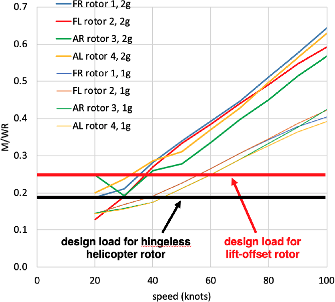
Figure 13 shows the calculated mean hub moments for the four rotors on the quadrotor aircraft, in level flight and 2g turn. The hub moment is given as lift offset = moment divided by thrust times rotor radius. With no flap hinge and no cyclic pitch, the rotor in edgewise flight operates with increasing lift offset as speed increases. For reference, the design hub moments are shown in Fig. 13 for typical hingeless rotors (Bo-105 level flap stiffness with 10 deg tip-path plane tilt) and lift offset rotors (design load for 200–250 knot aircraft).
Quadrotor (fixed pitch, hingeless rotors) mean hub moments in level flight and 2g turn (rotor designation: FR = front right, FL = front left, AR = aft right, AL = aft left); lift offset is M/WR = hub moment divided by thrust times rotor radius.
All UAM designs will likely require active control of rotorcraft vibration. Fixed-frame active vibration alleviation is common for rotorcraft. In addition, up to 90% reduction of loads and vibration using higher-harmonic control (HHC) or individual blade control (IBC) has been demonstrated through analysis, wind tunnel test and flight test [Reference Johnson86]. The UAM designs presented here have technology factors that represent the weight of vibration alleviation systems, excluding HHC or IBC.
6.5 Propulsion system weights
The trend in UAM to explore electric, and in particular distributed electric propulsion (DEP), has introduced the need to model motors, generators, motor controllers, heat exchangers, wiring, and batteries. Since 2014, NDARC has had the capability to model electrical propulsion system components, and as more aircraft have been modeled, further empirical and semi-empirical models for elements in the electrical propulsion system have been added to NDARC’s built-in capabilities.
Researchers at NASA have used the reference aircraft designs to explore electric architectures including DC, DC/AC, turboelectric and parallel hybrid [Reference Hanlon, Thomas, Csank and Sadey35, Reference Thomas, Chapman, Alencar, Hasseeb, Sadey and Csank51], resulting in extensions to the NPSS software tool. Other research has looked at power transmission wiring design for different material systems [Reference Aretskin-Hariton, Schnulo, Hendricks and Chapman36], finding that the minimisation of vehicle weight may favor lower-density higher-resistance wiring for some architectures. Research into thermal management systems for electric VTOL applications have found that the high power, low mass-flow and small temperature-gradient conditions of eVTOL aircraft in hover present a challenge for cooling design that probably demands a dedicated fan-driven heat exchanger, rather than being able to utilise surface cooling as would be possible for an electric fixed-wing aircraft [Reference Chapman, Hasseeb and Schnulo53].
Two particular design trades for electric propulsion systems are indicative of the new trades, which may be considered and modeled with the advent of electric propulsion: direct-driven rotors versus motor-plus-gearbox; and fewer large rotors driven by larger motors versus many smaller rotors driven by smaller motors (DEP). The weight of the motor plus transmission of an electric rotorcraft is shown in Fig. 14, as a function of rotor radius for a disk loading of 4 lb/ft2 and tip speed of 550 ft/sec (typical of the present designs). These weights are calculated using parametric equations for motor and drive system weights [Reference Johnson11], with technology factors appropriate for future designs. N is the motor speed (rpm) for cases with a transmission. For direct drive the motor speed equals the rotor speed. These results show that for current and projected future technology, a high-speed (low-torque) motor with an advanced transmission is lighter than direct drive. For direct drive to be the lighter design approach, a light-weight, high-torque motor is required, operating with large mean and oscillatory loads from the rotor.
Motor+transmission weight variation with rotor size and motor speed N (rpm).
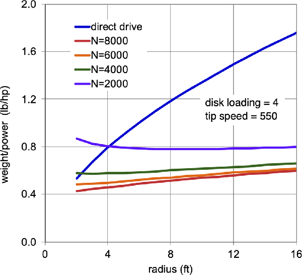
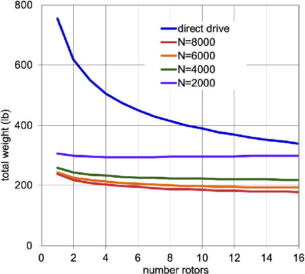
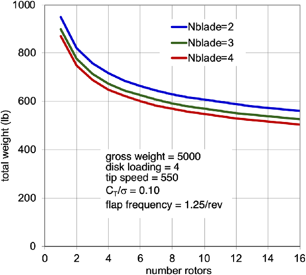
Figure 15 shows the motor plus transmission weight variation with number of rotors, for a disk loading of 4 lb/ft2, tip speed of 550 ft/sec, and aircraft weight 5,000 lb. Figure 16 adds the rotor weight to the motor and transmission weight, for design CT/ $\sigma$
= 0.10 and flap frequency of 1.25/rev (typical of hingeless helicopter rotors). The rotor weight is calculated using parametric equations [Reference Johnson11], which are based on data that includes aircraft weights and rotor diameters corresponding to these designs. Considering just the propulsion system (motor, transmission and rotor), the weight decreases significantly as the number of rotors increases (Fig. 16). Similar results are obtained considering turboshaft engines instead of electric motors, and for a large range of aircraft size. This result is therefore not consistent with the observation that for helicopter designs the single-main-rotor configuration (even with a tail rotor) is preferred to tandem or side-by-side aircraft types. Usually, adding the weight and drag of the structure that supports the rotors changes the optimum solution. Figure 6 shows the empty weights for the concept vehicles designed for the UAM mission. With eight lifting rotors, the lift+cruise type has higher structural weight even though it has good cruise efficiency.
$\sigma$
= 0.10 and flap frequency of 1.25/rev (typical of hingeless helicopter rotors). The rotor weight is calculated using parametric equations [Reference Johnson11], which are based on data that includes aircraft weights and rotor diameters corresponding to these designs. Considering just the propulsion system (motor, transmission and rotor), the weight decreases significantly as the number of rotors increases (Fig. 16). Similar results are obtained considering turboshaft engines instead of electric motors, and for a large range of aircraft size. This result is therefore not consistent with the observation that for helicopter designs the single-main-rotor configuration (even with a tail rotor) is preferred to tandem or side-by-side aircraft types. Usually, adding the weight and drag of the structure that supports the rotors changes the optimum solution. Figure 6 shows the empty weights for the concept vehicles designed for the UAM mission. With eight lifting rotors, the lift+cruise type has higher structural weight even though it has good cruise efficiency.
Motor+transmission weight variation with number of rotors and motor speed N (rpm).
Motor+transmission+rotor weight variation with number of rotors and number of blades.
6.6 Structural weights
With the introduction of new aircraft types having very different structural arrangements and different loading conditions, the use of empirical models based on existing helicopters, tiltwings, tiltrotors and fixed wing aircraft is of questionable validity. For the initial design work on the NASA UAM concept vehicles, the existing weight relationships in NDARC were used to model the vehicles, with adjustments to capture the likely impact of design differences. For instance, the side-by-side aircraft was modeled with a tiltrotor wing for the rotor support beam, using the jump takeoff sizing and preventing the whirl-flutter constraint from becoming active. For the quadrotor rotor support beams, a fixed-weight increment was added to NDARC based on an external calculation of the support beam weight. For the lift+cruise aircraft, the wing was modeled with the NDARC fixed-wing weight equation, and the rotor supports were modeled using the same methodology as applied for the quadrotor.
To address the structural weight uncertainty in the absence of any certified multi-rotor UAM aircraft to be used in development of new weight models, NASA has undertaken to introduce higher-fidelity weight assessment into conceptual design while trying to maintain the flexibility and lack of detailed information that are key features of the conceptual design stage of development. M4 Structures Studio [Reference Winter, Márquez and Scheneman23] is a tool that interfaces between parametric conceptual geometry in OpenVSP [Reference Hahn24] and NASTRAN to rapidly and robustly build finite-element models and maintain the parametric connection to the conceptual design geometry. Using this tool, the structural weights of the initial reference aircraft are predicted to have been in some instances conservatively heavy (side-by-side in [Reference Winter, Márquez and Scheneman23]) and in other instances optimistically light (lift+cruise in [Reference Winter, Márquez and Scheneman23]).
As UAM vehicles go through certification and enter operational service, NASA will make an effort to gather as much information as possible about actual weights and driving load conditions, and use this information to calibrate weight models and technology factors.
6.7 Handling qualities
The NASA concept vehicles are being used in explorations of the handling qualities and resulting design implications of these new rotorcraft configurations [Reference Malpica and Withrow-Maser40, Reference Schuet, Malpica, Lombaerts, Kaneshige, Withrow, Hardy and Aires47, Reference Withrow-Maser, Malpica and Nagami60, Reference Withrow-Maser, Malpica and Nagami75]. Similar investigations are in progress throughout the industry [Reference Walter, McKay, Niemiec, Gandhi and Ivler87–Reference Walter, McKay, Niemiec, Gandhi and Ivler91]. In [Reference Withrow-Maser, Malpica and Nagami75], control models of three vehicles (the quadrotor, an octocopter and the lift+cruise aircraft) were created and compared to determine the effect of rotor number and disk loading on control margin and design. All of these aircraft had electric propulsion with rpm control. In variable rotor speed-controlled vehicles, the propulsion system is directly in the path of the control system, which means the stability and control of the vehicle must be well understood and considered in the process to determine power requirements and the related overall weight of the vehicle.
NDARC was used to size the three, six-passenger vehicles to the same mission. SIMPLI-FLYD [Reference Lawrence, Theodore, Johnson and Berger21] was then utilised to generate the bare airframe model. Flight control systems were synthesised using CONDUIT [Reference Tischler, Colbourne, Morel, Biezad, Levine and Moldoveanu92] to a common set of handling qualities-oriented guidelines following a multi-objective function optimisation procedure. A model following control system architecture was used, with an integrated electric motor and speed controller. The general optimisation philosophy was to jointly minimise motor usage and crossover frequency, while primarily enforcing closed-loop robust stability margin and performance constraints — disturbance rejection bandwidth (DRB) (and disturbance rejection peak) for the main (heave, roll, pitch and yaw) control loops and minimum steady-state error for the engine speed controller (ESC) loops. Additionally, constraints to ensure minimum eigenvalue damping and crossover frequency were imposed.
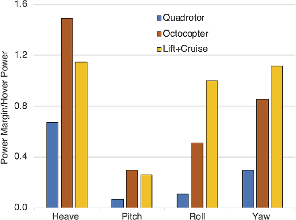
All three vehicles met Level 1 handling qualities specifications when the motor current was not constrained. For all three vehicles, the heave and yaw axes demanded more actuator usage (rms current) than the roll and pitch axes. Between heave and yaw, heave was the more demanding because of the dependence of heave on the engine speed controller. The optimised ESC gain and phase margins were large, so the motor control was not a limiting factor. When actuator usage was translated to current margin, torque margin, and power margin, heave was the most demanding axis, followed by yaw, roll, and then pitch for all three vehicles (Fig. 17). the required motor power and torque margins, relative hover, are Pmax/Phover = 1.67 for quadcopter, 2.49 for octocopter and 2.15 for lift+cruise aircraft. The results emphasise the importance of an accurate motor model within the control system architecture.
Power margin (as fraction of hover power) required to achieve level 1 handling qualities [Reference Withrow-Maser, Malpica and Nagami75].
NASA is also conducting a series of human-in-the-loop (HITL) simulation studies in the NASA Ames Vertical Motion Simulator (VMS). A simulation completed in 2021 investigated the connection between engine/motor usage, heave-axis control law design requirements and handling, and ride qualities for all-electric multirotor (quadrotor) architectures using rotor collective or rotor speed (RPM) for control. The studies considered the six-passenger reference quadrotor [Reference Silva, Johnson, Antcliff and Patterson6] and a specially designed RPM-controlled variant [Reference Withrow-Maser, Malpica and Nagami75]. The first aircraft was employed as the test control subject, and theoretically configured to be in deep Level 1 handling qualities according to ADS-33. The RPM-controlled variant was configured with varying heave axis pilot response time constants and feedback loop disturbance rejection bandwidths. This approach permitted an examination of tradeoffs in required engine power and handling qualities performance. Low-speed and hover-handling qualities of these configurations, with an Attitude Command-Attitude Hold response type, were evaluated by rotorcraft experimental test pilots in a combination of ADS-33 and specially tailored, UAM-representative mission task elements that emphasised precision over pilot aggressiveness. Preliminary trends frequently showed performance degradation with increased pilot aggressiveness. However, increased time for manoeuvring did not universally correlate with an ability to be more precise. Also, to gain initial insight into UAM passenger susceptibility to motion sickness during flight under smooth (collective control with high-disturbance rejection bandwidth) and moderately rough (RPM control with medium-disturbance rejection bandwidth) flight conditions, a second, complementary study was conducted in the VMS using passenger test subjects. Each participant took two brief (approximately 10 minute) prerecorded simulated quadrotor flights that took off, cruised at an altitude of about 500 ft and then landed at the same San Francisco vertiport. Preliminary findings suggest statistically significant increases in motion sickness symptoms reported, with positive correlation with individual predisposition to motion sickness, for flight under RPM control (medium-disturbance rejection bandwidth) compared to preflight baselines.
6.8 Safety and airworthiness
Airworthiness approval means a document, issued by the FAA for an aircraft, which certifies that the aircraft conforms to its approved design and is in a condition for safe operation (14 CFR 21.1(b)(2)). While certification requirements and procedures for air taxi aircraft may be debated, negotiated, or even contested, for aeromechanics research the focus is on safe operation. Every innovative aircraft type and non-traditional propulsion system requires an extensive failure mode, effects and criticality analysis (FMECA). Important for air taxi aircraft are crashworthiness and the consequences of propulsion system failure. Crashworthiness requirements affect design of airframe structure, landing gear, and passenger accommodation and restraint. Propulsion system failures must be considered in detail. In particular, single as well as complete engine failure must be considered, with requirements for control and methods for safe landing. In the concept vehicles, degraded weather operation, propulsion system failures and crashworthiness have been assumed to be requirements, and technology factors representing these design considerations have been applied.
6.9 Reliability and safety assessments
NASA commissioned several investigations to contrast major design differences of UAM aircraft and explore the safety and reliability implications from the perspective of vehicle design, propulsion architecture and flight dynamics and control [Reference Darmstadt, Catanese, Beiderman, Dones, Chen, Mistry, Babie, Beckman and Preator32, Reference Beiderman, Darmstadt, Dillard and Silva68–Reference Darmstadt, Pathak and Mistry70, Reference Darmstadt, Pathak, Chen, Mistry, Arkebauer, Beiderman, Dillard, Zierten, Beckman, Monroe, Catanese, Greene and Preator84–Reference Justin, Patel, Bouchard, Gladin, Verberne, Li, Ozcan, Rajaram, Mavris, D’Arpino, Aldemir, Rizzoni, Türkmen, Mayo and Bivens85]. The industry is pursuing the issues of UAM aircraft safety [Reference Woodham, Graydon, Borer, Papathakis, Stoia and Balan93–Reference Bendarkar, Behere, Briceno and Mavris95], particularly since EASA’s issue of special conditions for VTOL certification and the proposed means of compliance [96–97]. EASA SC-VTOL-01 establishes certification criteria for vertical takeoff and landing vehicles with unique propulsion and control architectures, including distributing the flight controls and electric propulsion elements.
In the initial investigation sponsored by NASA [Reference Darmstadt, Catanese, Beiderman, Dones, Chen, Mistry, Babie, Beckman and Preator32, Reference Beiderman, Darmstadt, Dillard and Silva68], the failure modes and hazards associated with four NASA concept vehicles (1-passenger quadcopter, 6-passenger side-by-side and lift+cruise and 15-passenger tiltwing) were identified and a functional hazard analyses (FHA) and failure modes and effects criticality analyses (FMECA) was performed. A Fault Tree Analysis (FTA) was created for each of the concept vehicles. In addition, conceptual designs of a notional power-train configuration for each of the four concept vehicles were developed to support the reliability and safety analysis for the study. Hazards were identified and the severity of each were categorised in the FHA. Guidelines for reliability targets for both the air vehicle and the operation in the UAM mission were provided. This study provided a methodology for evaluating the safety and reliability of a propulsion architecture.
The recent work sponsored by NASA [Reference Darmstadt, Pathak and Mistry70, Reference Darmstadt, Pathak, Chen, Mistry, Arkebauer, Beiderman, Dillard, Zierten, Beckman, Monroe, Catanese, Greene and Preator84, Reference Justin, Patel, Bouchard, Gladin, Verberne, Li, Ozcan, Rajaram, Mavris, D’Arpino, Aldemir, Rizzoni, Türkmen, Mayo and Bivens85] developed for several of the concept vehicles an all-electric distributed propulsion and flight control (DPFC) architecture that will have no more than 10–9 catastrophic failures per flight hour, based on the requirements of EASA SC-VTOL-01. The DPFC architecture included electrical power and distribution system, drive and power system, thermal management system and flight control system. Specific questions regarding number of rotors, control schemes and propulsion type were examined:
-
A) impact of number of rotors: compare hexacopter and octocopter (electric, rpm control)
-
B) impact of control schemes: compare rpm control and collective control (hexacopter, electric)
-
C) impact of propulsion architectures: compare electric, hybrid and turboshaft (quadcopter, collective control, with cross shaft)
The assessments were in terms of the safety level achieved, and aircraft components and features needed to meet the required safety level. Transient stability and control models were developed to help inform vehicle handling characteristics and for system requirements definition. To help characterise safety in all operating environments, transient power requirements were investigated in the presence of atmospheric disturbances representative of an urban canyon environment.
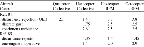
Sizing criteria for power plant components are not currently available for multirotor aircraft; therefore, early stability and control simulations are required to characterise power transients to feed design sizing for both normal and emergency flight conditions. Such simulations show: (a) removing interconnecting shafts results in higher power transients at each motor; (b) rpm control results in higher power transients at each motor, compared to collective control; (c) increasing the number of rotors has a small increase in power transients, but changes to power transients are not as severe as the change to no interconnecting shafts or to rpm control. Table 4 summarises the results for power transients.
Required motor power transient capability, P/Phover
DPFC architecture excursions show realistic means to UAM aircraft safety using hybrid-electric or turboshaft power sources: the required safety levels can be achieved using state-of-the-art technology. The turboshaft propulsion architecture is the most reliable of the three considered. Battery networks located at each motor system were required to have at most 10–10 failures per flight hour to comply with SC-VTOL-01, which was accomplished by pairing redundant battery packs at each motor, with an impact on aircraft weight. The aircraft with collective control and rpm control exhibit similar reliability levels. Increasing the number of rotors (from 6 to 8) does not inherently increase reliability, due to common cause failures, particularly in the battery system.
All aircraft evaluated likely have paths to comply with the stringent, probabilistic catastrophic failure criteria of EASA SC-VTOL-01. However, the stability and control models showed large power transients that must be addressed. Preliminary system safety assessment results show that future work is needed in single load path structures, high voltage power storage and distribution, and in motor/rotor overspeed protection.
EASA SC-VTOL-01 extends fail-safe and redundancy management design techniques to leverage the potential to segregate failures through unique, multirotor configurations, with stringent design requirements associated with redundancy management and single or multiple load path designs. SC-VTOL-01 requires that a single failure must not have a catastrophic effect upon the aircraft. Certification of conventional rotorcraft configurations imposes similar single failure criteria, except that some exceptions are allowed if the probability of failure is extremely remote. SC-VTOL-01 does not permit catastrophic effects of single failures, regardless of the probability of failure; thus the safety assessment process must demonstrate that all single failures are not catastrophic. The single failure criterion has a potentially large impact on all aircraft intended to be type certificated under SC-VTOL-01. Single-load path structures are of prime concern, being mechanical systems in which redundant load path structures can be difficult to integrate. For example, blade loss, rotor loss or excessive vibrations leading to structural failure are reasonable and conceivable potentially catastrophic failure modes that must be addressed.
6.10 Cost
Purchase cost of aircraft is roughly (to about 20% accuracy) driven by aircraft empty weight, installed power, and complexity, plus the costs of electronic systems. For electric propulsion, the cost of batteries should be explicitly included in the purchase cost estimate. Data are available for maintenance cost of helicopters flying traditional missions, but not for unconventional aircraft types engaged in air taxi operations. A significant component of operating costs is the cost of fuel or energy. If the mission range is small enough so that electric propulsion is feasible, energy costs are generally smaller for the all-electric propulsion configuration, even though the aircraft weight is larger.
A method to estimate the purchase price of rotary wing aircraft was developed by Harris and Scully [Reference Harris and Scully98], revised and extended by Scott [Reference Scott99–Reference Scott100]. The method gives the price within 20%, as ${\rm{Price}} = K\left( {{\rm{SF}}} \right)$
, with the size factor
${\rm{Price}} = K\left( {{\rm{SF}}} \right)$
, with the size factor
 \begin{align}{\rm{SF}} = {\rm{W}}{{\rm{E}}^{0.4638}}{P^{0.5945}}\end{align}
Here ${\rm{WE}}$
is the weight empty and
${\rm{WE}}$
is the weight empty and $P$
is the installed power; the factor
$P$
is the installed power; the factor $K$
depends on the aircraft type, and some measures of complexity. The equation
$K$
depends on the aircraft type, and some measures of complexity. The equation ${\rm{Price}} = K\left( {{\rm{SF}}} \right)$
is applicable to helicopters, tiltrotors, general aviation and airlines [Reference Justin, Patel, Bouchard, Gladin, Verberne, Li, Ozcan, Rajaram, Mavris, D’Arpino, Aldemir, Rizzoni, Türkmen, Mayo and Bivens85], and to commercial turboprops and unmanned aircraft [Reference Johnson86]. The size factor
${\rm{Price}} = K\left( {{\rm{SF}}} \right)$
is applicable to helicopters, tiltrotors, general aviation and airlines [Reference Justin, Patel, Bouchard, Gladin, Verberne, Li, Ozcan, Rajaram, Mavris, D’Arpino, Aldemir, Rizzoni, Türkmen, Mayo and Bivens85], and to commercial turboprops and unmanned aircraft [Reference Johnson86]. The size factor ${\rm{SF}}$
appears as a universal scaling parameter for aircraft cost (Fig. 18). The NASA concept vehicles have
${\rm{SF}}$
appears as a universal scaling parameter for aircraft cost (Fig. 18). The NASA concept vehicles have ${\rm{SF}} = $
1,500 to 6,000, which would imply a unit flyaway cost in the range
${\rm{SF}} = $
1,500 to 6,000, which would imply a unit flyaway cost in the range $ {\$} $
3M to
$ {\$} $
3M to $ {\$} $
10M following the data in Fig. 18. However, the UAM industry is projecting prices an order of magnitude less than existing rotorcraft and turboprops when high-rate manufacturing is employed and larger numbers of UAM vehicles are produced. There is no data yet to evaluate the factor
$ {\$} $
10M following the data in Fig. 18. However, the UAM industry is projecting prices an order of magnitude less than existing rotorcraft and turboprops when high-rate manufacturing is employed and larger numbers of UAM vehicles are produced. There is no data yet to evaluate the factor $K$
appropriate for UAM aircraft, but it is reasonable to use this size factor to estimate the relative costs of the concept vehicles.
$K$
appropriate for UAM aircraft, but it is reasonable to use this size factor to estimate the relative costs of the concept vehicles.
Unit flyaway price for several classes of rotary wing and propeller aircraft [Reference Scott99].
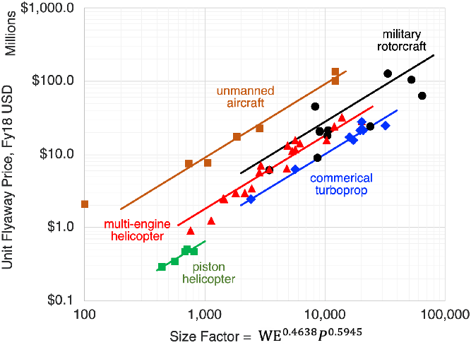
6.11 Noise and annoyance
The UAM concept vehicles have been designed with low hover tip speed, in anticipation of a significant requirement for noise reduction in the urban environment. Rotor-rotor interactions, such as rear rotors operating in the wake of front rotors, and wake interactions on retreating sides of overlapped side-by-side rotors, will increase blade-vortex interaction noise. Blade shape and spacing can be optimised for low blade-vortex-interaction and high-speed-impulsive noise. Noise metrics and requirements are established by regulation for rotorcraft, but suitability and applicability of these to air taxi operations must be established.
To compare the impact of design variables on the aircraft noise, the noise certification requirements as specified in FAR Part 36, Appendix H, “Noise Requirements for Helicopters,” [101] are used. The aircraft is flown over three microphones, at the centerline and 150 m to starboard and port. The operating conditions are sea level pressure, and a temperature of 25oC. Three trajectories are flown: takeoff, flyover and approach. The takeoff profile starts 500 m from the center microphone, 20 m above ground level, and is flown at best rate of climb speed, Vy, and 100% maximum rated power (MRP). The flyover profile is 150 m above ground level, for these aircraft flown at 0.9VH, where VH is the speed at 100% maximum continuous power (MCP). The approach profile has a 6-degree descent angle, flown at Vy, 120 m above ground level at the center microphone. Certification requirements specify the maximum EPNL for these trajectories. NDARC was used to calculate Vy, VH, and the takeoff climb angle. CAMRAD II calculated the section loading at each condition, and AARON/ANOPP2 calculated the EPNL levels. For each of the reference vehicles, these noise metrics were calculated for a range of design tip speeds.
The aircraft designed to the UAM mission all have relatively high takeoff performance, due to the 900 ft/min climb rate requirement. This results in a higher installed power, so that for the takeoff noise certification condition, the aircraft is both further from the observer than for existing helicopters and the rotor is operating with a quickly convecting wake. These two effects combine to reduce the noise for the QSMR, quadrotor, and side-by-side by at least 10 EPNdB compared to helicopters of similar weight, as seen in Fig. 19 (takeoff). The colours and markers are consistent in the figures, with QSMR a yellow circle, quadrotor a blue square, lift+cruise a red triangle and side-by-side a purple diamond. The existing helicopter data are shown as grey circles, with grey lines for Stage 2 and Stage 3 limits. The lift+cruise in compound mode trim is the loudest and heaviest of the vehicles, due in large part to the high number of rotors, rotor-rotor interactions and operating at a higher disk loading due to the rotor radius being constrained. Flyover results with varying rotor tip speed are shown in Fig. 19 (flyover). For flyover, the QSMR, quadrotor and side-by-side are also in general quieter than existing helicopters, while the lift+cruise is once again similar to existing helicopters. Approach results for varying rotor tip speed are shown in Fig. 19 (approach). Approach noise is close to existing helicopters if the tip speeds are at the higher end of the range of speeds examined, but noise quickly reduces as tip speed goes to the lower end of the range. The lowest tip speed, 375 ft/s for the quadrotor, does not improve the approach noise or the flyover noise compared to the 400 ft/s case.
Noise and max gross weight for the four types of aircraft with varying tip speed compared to existing helicopters (QSMR yellow circle, quadrotor blue square, lift+cruise red triangle, side-by-side purple diamond).
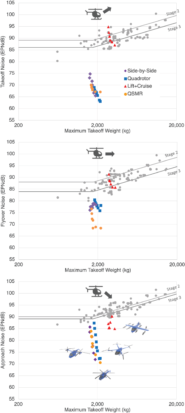
Vehicle flyaway cost generally increases with rotor tip speed reduction as shown in Fig. 20 (relative costs are shown in this figure). The increase in cost with reducing tip speed is not always accompanied by a reduction in noise, and this trade is likely to be of importance in UAM conceptual design.
Approach noise and relative flyaway cost for the four types of aircraft with varying tip speed (QSMR yellow circle, quadrotor blue square, lift+cruise red triangle, side-by-side purple diamond).
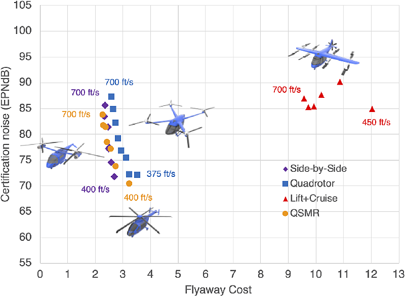
7.0 Concluding remarks
NASA is conducting investigations in Advanced Air Mobility (AAM) aircraft and operations. AAM missions are characterised by ranges below 300 nm, including rural and urban operations, passenger carrying as well as cargo delivery. Urban Air Mobility (UAM) is a subset of AAM and is the segment that is projected to have the most economic benefit and be the most difficult to develop. The NASA Revolutionary Vertical Lift Technology project is developing UAM VTOL aircraft designs that can be used to focus and guide research activities in support of aircraft development for emerging aviation markets. These NASA concept vehicles encompass relevant UAM features and technologies, including propulsion architectures, highly efficient yet quiet rotors, and aircraft aerodynamic performance and interactions. The configurations adopted are generic, intentionally different in appearance and design detail from prominent industry arrangements. Already these UAM concept aircraft have been used in numerous engineering investigations, including work on meeting safety requirements, achieving good handling qualities, evaluating vehicle crashworthiness, and reducing noise levels. The NASA concept vehicles for AAM and UAM operations have been described. Focusing on these concept vehicles, observations are made regarding the engineering trade space of Advanced Air Mobility aircraft.
The computational tools available for rotorcraft aeromechanics analysis and design are generally applicable to VTOL AAM aircraft. In particular, the toolchain has been capable of quantitatively trading several relevant noise reduction technologies and design approaches for aircraft that can perform the Urban Air Mobility mission. The tools are practical for early design applications, in terms of the amount of input required and the computation times.
A high level of battery technology, in particular high energy per weight at the pack level, is a prerequisite for successful development of electric VTOL aircraft. In addition to the direct impact on aircraft size and weight, low-weight batteries also enable the long endurance and range (large battery size) needed to keep hover currents reasonable.
Hingeless rotors or propellers in edgewise forward flight with low tip speed encounter high mean hub moments and blade oscillatory loads, resulting in high-weight rotor designs. Historical data reflecting proven design practices shows that the total propulsion system weight — motors, transmissions and rotors — decreases as the number of rotors increases, a result that holds for all VTOL aircraft sizes, different rotor types (hingeless and hinged), and different propulsion concepts (turboshaft and electric). This trend is, however, reversed when the weight of the structure holding the rotors is included, as illustrated by the concept vehicles.
An assessment of several vehicles (quadrotor, octocopter and lift+cruise configurations) using rpm control showed that Level 1 handling qualities specifications can be met when the motor current is not constrained. When actuator usage was translated to current margin, torque margin, and power margin, heave was the most demanding axis. The control design quantified the significant motor power margins (relative hover power) that must be included in the aircraft sizing. Similar results for transient power capability were found from simulations conducted as part of the reliability and safety assessments.
With AAM designs bringing new solutions to the problems of VTOL flight, there are new measures of success for the first aircraft. Safety and noise are the most important issues, not weight and power, maybe not even cost. The lack of flight experience with multi-rotor configurations utilising electric propulsion makes it imperative to adopt new, rigorous requirements for the response of the aircraft to failures. There are known design choices that will reduce the aircraft noise, and design trades can be made to minimise noise. Work focused on the NASA concept vehicles suggests that designing aircraft for low probability of catastrophic failure and for very low external noise will be possible. The design solutions will require aircraft that are larger and heavier than conventional rotorcraft, with more power and larger energy installed — but the concept vehicle designs imply that such aircraft are still feasible. After safe and quiet aircraft have pioneered the market and introduced passengers to the advantages of AAM, a maturing industry can be expected to return to weight, power, and cost as the classical measures of a good aircraft for the market.