

Introduction
Airborne radars have been used since the 1960s to profile stratigraphy and ice thickness, with extensive coverage over the large ice sheets in Greenland and Antarctica (Reference Drewry and MeldrumDrewry and Meldrum, 1978; Reference Dowdeswell, Drewry, Liestøl and OrheimDowdeswell and others, 1984; Reference AllenAllen, 2008). Early radars were centered near 60 MHz, and newer systems are centered near 150 and 195 MHz for sounding ice >4 km thick and recording englacial stratigraphy. Recently, bandwidths have been extended into the UHF range (Reference Kanagaratnam, Gogineni, Gundestrup and LarsenKanagaratnam and others, 2001, Reference Kanagaratnam, Gogineni, Ramasami and Braaten2004; Reference ForsterForster and others, 2014). These systems mapped englacial reflections from depths exceeding 200 m, far deeper than any conventional definition of firn depth. Here we discuss our recently developed fine-resolution 600–900 MHz pulsed-chirp radar and show its application to three topics of glaciological research: the cause of englacial reflections, firn compaction and radio-wave attenuation rates.
The cause of englacial reflection of radio waves is a topic of extensive research in the field of radioglaciology. Within firn, typically to a depth of <200 m, these reflections can be attributed to density changes (Reference Paren and RobinParen and Robin, 1975; Reference MillarMillar, 1982; Reference Arcone, Spikes, Hamilton and MayewskiArcone and others, 2004). At depths greater than this, density variations are too minute to contribute to resolvable reflective interfaces. The paradigm is that reflections below the firn are caused by conductivity changes (Reference MillarMillar, 1982; Reference Hempel, Thyssen, Gundestrup, Clausen and MillerHempel and others, 2000). Conductivity anomalies from acidic layers are 10−5 S m−1 on average and are expected to be no more than 10−4 S m−1 in the continental interior (Reference HammerHammer, 1980; Reference MillarMillar, 1982). These anomalies translate to interface reflection coefficients between −60 and −84 dB at our frequencies of operation, falling within the range of detectability of our radar. We recorded reflections within the firn and ice over interior regions of Greenland and West Antarctica. When we encountered cold ice with a smooth surface, we recorded reflections from depths of 650 m. To the best of our knowledge, this was the first successful instance of mapping interface reflections from this depth and with this bandwidth from an aircraft.
The mechanisms of firn compaction have important ramifications for the determination of ice-sheet mass balance via remote-sensing measurements. Knowledge of firn densification is critical to interpreting remote-sensing traces (Reference BretonBreton, 2011). Densification proceeds through three major stages: random particle settling, particle deformation and air bubble compression. Reflective horizons seen in firn are the result of density variations caused by seasonal changes in the rate of compression and recrystallization of summer melt. We found that radar traces from interior continental firn closely matched the statistical variability of density measured from ice cores. As all the interfacial two-way transmission coefficients are near unity and layer echoes are the combined response of multiple variations that fall within the radar resolution, this result was expected (Reference HarrisonHarrison, 1973; Reference GudmandsenGudmandsen, 1975).
Englacial radio-wave attenuation is of particular interest to the glaciological community (Reference Bogorodskiy, Pozdnyak, Trepov and Shremet’yevBogorodsky and others, 1982; Reference MacGregor, Winebrenner, Conway, Matsuoka, Mayewski and ClowMacGregor and others, 2007; Reference Jacobel, Welch, Osterhouse, Pettersson and MacGregorJacobel and others, 2009). Knowledge of attenuation rates is essential to evaluating the causes of englacial reflections and basal conditions; however, relatively little is known about attenuation rates and their spatial variation (Reference MacGregor, Winebrenner, Conway, Matsuoka, Mayewski and ClowMacGregor and others, 2007). Average attenuation rates reported over different regions of Antarctica vary approximately by a factor of three (Reference Jacobel, Welch, Osterhouse, Pettersson and MacGregorJacobel and others, 2009). Reference Corr, Moore and NichollsCorr and others (1993) and Reference Bentley, Lord and LiuBentley and others (1998) accounted for attenuation through calibrated ice-shelf measurements where the theoretical basal reflectivity of the ice–water interface is known. Reference Winebrenner, Smith, Catania, Conway and RaymondWinebrenner and others (2003) estimated attenuation through simple radio-wave propagation path length variations. Reference GoodmanGoodman (1975), Reference Paden, Allen, Gogineni, Jezek, Dahl-Jensen and LarsenPaden and others (2005) and Reference Peters, Blankenship and MorsePeters and others (2005) found absorption to be the dominant extinction factor and used a temperature/attenuation relationship model to estimate attenuation rates. In this work, we further investigate attenuation rates using calibrated radar data over regions with bed echoes of known theoretical reflectivity, such as ice shelves, ice caps and shallow glaciers.
We hypothesize that data collected with our ultrawideband UHF radar could determine the dominant cause of reflections in ice below the firn–ice transition, verify firn densification mechanism boundaries and allow for the calculation of ice attenuation rates. The existence of englacial interfacial horizons at 300 MHz bandwidth would indicate that conductivity could be affirmed as the main cause of reflections, reflectivity profiles should mirror density variability within firn, and calibrated surface and bottom echoes should supply enough information to calculate depth-averaged ice attenuation rates. Our objectives were to acquire airborne radar profiles of stratigraphy and ice beds. Our approach was to construct a fine-resolution radar with the ability to penetrate through glacial firn and shallow ice; choose transects that were likely to encounter smooth surfaces, deep firn–ice transitions and no unconformities; calibrate the data in relation to targets of known theoretical reflectivity; and calculate signal attenuation rates and interfacial reflectivities. We provided the fine-range resolution by chirping the transmit waveform. We chose a system gain to overcome spreading loss and the expected ice attenuation. We chose a receiver gain that places the receiver noise slightly above the analog-to-digital converter (ADC) quantization noise, allowing for significant post-processing dynamic range improvement through pulse compression and coherent integration. We focused on data from flight lines over cold regions in interior Greenland and West Antarctica, select ice caps in northernmost Canada, glacial ice shelves in northern Greenland, and the Ross Ice Shelf. For calibration purposes, data were collected over cold, smooth sea ice off the coast of northeast Greenland.
Early surface-based radar systems revealed the presence of stratification in the polar ice sheets. Reference Robin, Evans and BaileyRobin and others (1969), Reference GudmandsenGudmandsen (1975), Reference HarrisonHarrison (1973) and Reference CloughClough (1977) first discussed englacial interface echoes in sounding radar data collected in both Greenland and Antarctica. Reference GoodmanGoodman (1975), Reference Narod and ClarkeNarod and Clarke (1980) and Reference Narod, Clarke and PragerNarod and others (1988) demonstrated that short-pulse UHF radars were successful at penetrating glaciers and ice caps to depths between 300 and 600 m via multiple surveys conducted in Alaska and Canada. While these surveys focused on thickness measurements, some englacial reflections were also reported. Reference Arcone and DelaneyArcone and Delaney (1987) and Reference ArconeArcone (1991) performed thickness measurements of river and lake ice using a helicopter-mounted short-pulse UHF radar, measuring ice thickness as small as 5–10 cm. Additional experiments have been conducted using modified existing radar systems (Reference FujitaFujita and others, 1999; Reference Hempel, Thyssen, Gundestrup, Clausen and MillerHempel and others, 2000), commercial off-the-shelf radar systems (Reference ArconeArcone, 1996, Reference Arcone2002; Reference Kohler, Moore, Kennett, Engeset and ElvehøyKohler and others, 1997; Reference Arcone, Spikes and HamiltonArcone and others, 2005), vector network analyzer (VNA)-based radar systems (Reference Richardson, Aarholt, Hamran, Holmlund and IsakssonRichardson and others, 1997) and custom-built radar systems (Reference Kanagaratnam, Gogineni, Gundestrup and LarsenKanagaratnam and others, 2001, Reference Kanagaratnam, Gogineni, Ramasami and Braaten2004). The instrument described in this paper leverages the original work by Reference Kanagaratnam, Gogineni, Ramasami and BraatenKanagaratnam and others (2004). Results were reported by Reference Rodriguez-MoralesRodriguez-Morales and others (2013), Reference ForsterForster and others (2014) and Reference MedleyMedley and others (2013, Reference Medley2014). Reference Rodriguez-MoralesRodriguez-Morales and others (2013) revealed the presence of subsurface water layers inside the ice in coastal southeast Greenland through the combined analysis of snow radar (Reference PanzerPanzer and others, 2013), UHF radar and Multichannel Coherent Radar Depth Sounder/Imager (MCoRDS/I) data (Reference Rodriguez-MoralesRodriguez-Morales and others, 2013). Reference ForsterForster and others (2014) used data from this radar to further verify the presence of a water layer, referred to as the perennial firn aquifer, via high correlation with concurrent ice cores, concluding that this radar is capable of accurately mapping the presence and depth of a liquid water layer. Reference MedleyMedley and others (2013, Reference Medley2014) used data from this radar to successfully track internal layer interfaces in an effort to determine both spatial and temporal variations in snow accumulation over Thwaites and Pine Island Glaciers, West Antarctica.
The Instrument
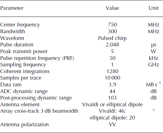
We designed and built a custom ultra-wideband pulsed-chirp radar with 300 MHz of bandwidth, centered at 750 MHz. It is designed to profile interfaces within polar firn and glacial ice. Table 1 summarizes the pertinent nominal radar parameters.
Summary of radar system parameters
The radar system is composed of a user interface, a digital section, an analog RF section and the antennas. Global positioning and inertial navigation (GPS/INS) information is ingested from an external system. Aboard the Twin Otter aircraft, a NovAtel SPAN-CPT GPS+IMU system is used. Aboard the NASA P-3 aircraft, the navigation and orientation data are provided by an Applanix POS AV 510 (Reference Rodriguez-MoralesRodriguez-Morales and others, 2013).
We selected the frequencies of operation to obtain fine resolution without interference from the communication and navigation equipment aboard the NASA P-3 (Reference KanagaratnamKanagaratnam, 2002). We chose a pulsed-chirp transmission scheme to obtain pulse compression gain while allowing for single-antenna operation using a transmit/receive (T/R) switch. A high input bandwidth ADC allowed for the direct digitization of received returns by means of bandpass sampling (Reference Vaughan, Scott and WhiteVaughan and others, 1991). The received signals are pulse-compressed digitally to generate time and range profiles.
We begin quantifying the performance of the radar by calculating the theoretical range resolution and accuracy. Range resolution, ΔR, defines the minimum distance for resolving two interfaces, and range accuracy, δ r, defines the maximum error of a measured layer depth based on the signal-to-noise ratio (SNR) of the received return. These figures of merit are defined by

and
where c is the speed of light, B is the bandwidth, ε r is the dielectric constant of the medium and k is the window-widening factor. For typical operating parameters, where k = 1.53, this radar has a theoretical range resolution of 77 cm in air (ε r = 1), 53 cm in firn (ε r = 2.1) (Reference Ulaby, Moore and FungUlaby and others, 1986a; Reference PanzerPanzer and others, 2013) and 43 cm in ice (ε r = 3.15) (Reference Ulaby, Moore and FungUlaby and others, 1986a). For a smooth land ice surface return, the expected SNR is 70 dB and the range accuracy, δ r, is 0.17 mm. For a deep internal layer return at a depth of ∼250 m, the expected SNR is 10 dB and δ r is 9.6 cm.
We further quantified performance in terms of the SNR using a link budget. Since the target ice interfaces are sufficiently flat within two or more Fresnel zones, we may consider them to be specular targets (Reference Ulaby, Moore and FungUlaby and others, 1986b). In this case, the received power appears to originate from an image point at twice the range; therefore, we can define the SNR for an interface as

where P T is the transmitted power, G is the measured antenna gain, λ is the wavelength at the center frequency, ΓA is the voltage reflection coefficient of the antenna, ΓL is the voltage reflection coefficient of a layer at depth, G PC is the pulse compression gain, G N is the coherent integration gain, G RX is the receiver gain, R A is the radar platform altitude, R I is the range between the ice surface and the target layer, L I is the ice extinction and P N_ADC is the effective noise floor of the ADC.
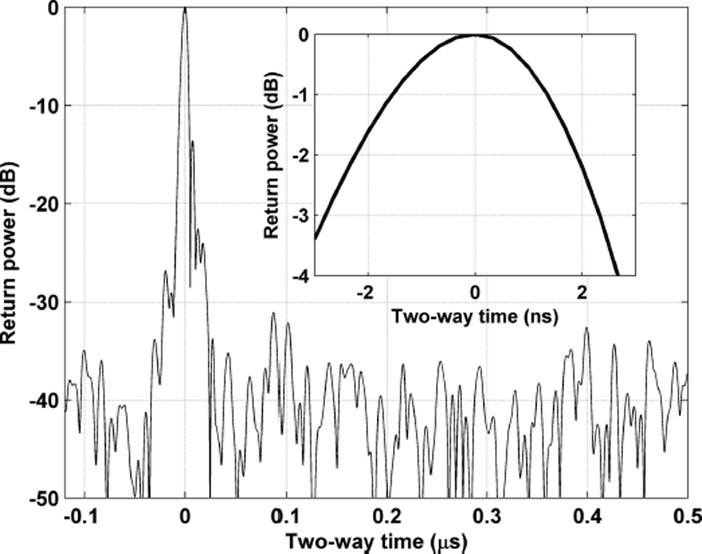
We conducted laboratory tests using an optical delay line as a simulated specular target at a distance of 500 m, the nominal operational altitude. Figure 1 shows a sample pulse-compressed waveform. The peak response agrees well with the theoretical SNR of ∼42 dB. The inset shows that the 3 dB width of the peak response is ∼5 ns, or an approximate range resolution of 75 cm, matching well with theory.
Time domain response obtained using an optical delay line as a simulated specular target. Inset shows a close-up of the response around the main peak.
The system performance was also verified in flight by recording data over smooth sea ice. (The root-mean-square surface roughness of the sea ice has been measured to be <0.03 cm at C-band (Reference PanzerPanzer and others, 2013), which means we can safely assume it is smooth at UHF frequencies.) Figure 2 shows a sample compressed waveform from smooth sea ice off the east coast of Greenland. We used the dielectric constant of pure ice (ε r = 3.15) (Reference Ulaby, Moore and FungUlaby and others, 1986a) as the surface density to calculate a surface voltage reflection coefficient of −5.5 dB and a surface return SNR of 77.2 dB. This agrees well with the 78 dB surface return SNR seen in Figure 2. A close-up of the surface response is shown in the figure inset. The 3 dB width of the surface response is ∼5 ns, or a range resolution of 75 cm, matching well with theory.
Time domain response from smooth sea ice. Inset shows a close-up of the response around the main peak.

The system performance was further quantified using data collected over the dry snow zone. Within the dry snow zone, average surface snow densities are 330 kg m−3 (Reference PatersonPaterson, 1994) and therefore have an average dielectric constant of ε r = 1.53 (Reference Ulaby, Moore and FungUlaby and others, 1986a) and a surface voltage reflection coefficient of −9.3 dB. This results in a calculated surface return SNR of 69.5 dB; this agrees well with the surface return SNR of 70 dB over central Greenland (Fig. 3). Again, the 3 dB width of the surface response is ∼5 ns, or a range resolution of 75 cm, matching well with theory.
Time domain response from interior land ice. Inset shows a close-up of the response around the main peak.

Field Experiments
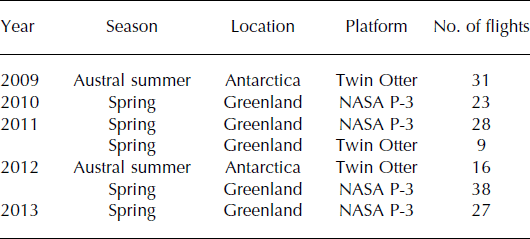
We first flew the radar aboard a Twin Otter in Antarctica during the 2009/10 austral summer season, supported by the US Antarctic Program and based primarily at Byrd Camp in West Antarctica. Survey flights focused on Thwaites and Pine Island Glaciers, including fine-scale grids on Thwaites Glacier near concurrent seismic measurements performed by The Pennsylvania State University (PA, USA). Since 2010, we have flown the radar aboard the NASA P-3 as part of Operation IceBridge (OIB), collecting measurements over many regions of central Greenland and select major outlet glaciers. In spring 2011, we flew the radar aboard a Twin Otter concurrent with the spring OIB campaign, but focused on fine-scale grids over Jakobshavn and Helheim glaciers and Kangiata Nunaata Sermia. We flew the radar aboard a Twin Otter for the final time during the 2011/12 Antarctic season, focusing on Byrd Glacier and its catchment. Table 2 summarizes the field campaigns flown. Figures 4 and 5 show flight lines where valid radar data were collected in Greenland and Antarctica, respectively. The flight lines are segregated by year and platform. All missions were flown at a nominal altitude of 500 m.
Accumulation radar field campaign summary
Flight lines where accumulation radar data were collected over Greenland and the Arctic during the 2010–13 P-3 and 2011 Twin Otter field experiments.

Flight lines where accumulation radar data were collected over Antarctica during the 2009/10 and 2011/12 Twin Otter field experiments.

Englacial Reflections
Reflections from internal interfaces have been recorded with this radar system over regions of central Greenland and West Antarctica. Over cold regions of central Greenland where ice temperatures are −30°C or lower (Reference RobinRobin, 1972) and signal attenuation is relatively low, we often recorded reflections from interfaces below the maximum expected firn–ice transition depth of 200 m. Figure 6 shows a radargram from central Greenland indicating the presence of interface reflections at propagation velocity-corrected depths in excess of 600 m. These data were collected during the spring 2012 NASA OIB experiment. The diamond marker at 77.2°N, 42.6°W in Figure 4 indicates the approximate location of this radargram. We detrended the radargram to enhance the visibility of deeper layering. A sample normalized received power trace is shown on the right side of the radargram (Fig. 6). The trace was not detrended to preserve the actual relative amplitudes. The position of this trace is marked by the vertical line, and the ice surface and surface multiple are annotated. The surface multiple is an artifact caused by the retransmission of the received surface return reflecting off the bottom of the aircraft. The surface multiple follows the change in altitude of the aircraft. At the nominal survey altitude of 500 m we expect to see this multiple at an average depth of 270 m.
Radargram of interior Greenland showing resolvable interface reflections.

Two mechanisms have been proposed as the cause of observed reflective interfaces in polar ice: variations in density and variations in the loss tangent (Reference Paren and RobinParen and Robin, 1975; Reference MillarMillar, 1982). Density variations are the result of compression and recrystallization of snow particles. This mechanism dominates above the firn–ice transition depth, typically at a maximum of 200 m. Below this transition, the paradigm is that reflections result from changes in the loss tangent, which are believed to occur due to changes in conductivity (Reference MillarMillar, 1982; Reference Hempel, Thyssen, Gundestrup, Clausen and MillerHempel and others, 2000), where conductivity is the product of the ion concentration (acidity) and mobility. Reference Paren and RobinParen and Robin (1975) and Reference ParenParen (1981) found that the reflection coefficient of a layer of acidic ice with a given thickness can be estimated from the deviation of the conductivity of the layer from the background conductivity of the surrounding ice. Using numerical modeling, Reference CloughClough (1977) found that, for a grouping of closely spaced reflecting layers with varying thicknesses and conductivities, the total reflection coefficient can be approximated as a single interface with an averaged change in conductivity that is weakly dependent on the layer thickness. Therefore, the reflection coefficient of a given horizon can be approximated by
where Δσ is the conductivity deviation and f is the radar frequency. Conductivity anomalies measured from ice cores in central Greenland are ∼10−20 dB above the background conductivity of 10−6 S m−1 (Reference HammerHammer, 1980; Reference MillarMillar, 1982). Interface reflection coefficients range from −60 dB for larger anomalies at the lowest frequency of operation to −84 dB for small anomalies at the highest frequency of operation. Given the operational parameters of our radar system, aircraft height and expected propagation loss, we are able to detect reflection coefficients as low as −80 dB near the maximum expected firn–ice transition at a depth of 200 m. We are also able to detect reflection coefficients as low as −67 dB at a depth of 650 m, the deepest returns we observed in our dataset. We conclude that conductivity anomalies are the dominant reflective mechanism observed by our radar below the firn–ice transition. Figure 7 shows an enlarged view of the deepest layers seen below 600 m. We applied a custom bas-relief filter to the image to enhance the visibility of layering. The location of this view is marked with an X in Figure 6. At this point, the returns are just a few dB above the noise floor. We found the separation between adjacent bright interfaces was often between 50 cm and 1.7 m.
Enlarged portion of interior Greenland radargram around deepest reflections. A custom bas-relief filter was applied to enhance layering visibility.

Most of the data showing firn and ice stratigraphy were collected from ideally stratified areas. During the 2009/10 Antarctic field season, we collected data over portions of the Pine Island Glacier (PIG) catchment that exhibited significant undulating features. Figure 8 shows an example radargram from this region. The diamond marker at 76°S, 93.9°W in Figure 5 indicates the approximate location of this radargram. We did not artificially flatten the surface to preserve the appearance of the surface topography. The maximum depth and SNR of received reflections appear to be dependent on surface slope. Surface visibility is reduced with increasing slope and is likely a result of reflected energy being scattered off-vertical. Figure 9 shows an enlarged view of the region of layer pinching marked with an X in Figure 8. We applied a custom bas-relief filter to the image to enhance the visibility of layering and highlighted a pair of pinched layers. We were able to resolve layering to a minimum spacing of ∼55 cm.
Radargram of Pine Island Glacier catchment showing significant undulations.

Enlarged portion of PIG radargram showing layer pinching. A custom bas-relief filter was applied to enhance layering visibility. An example of layer pinching is highlighted.

Firn Compaction
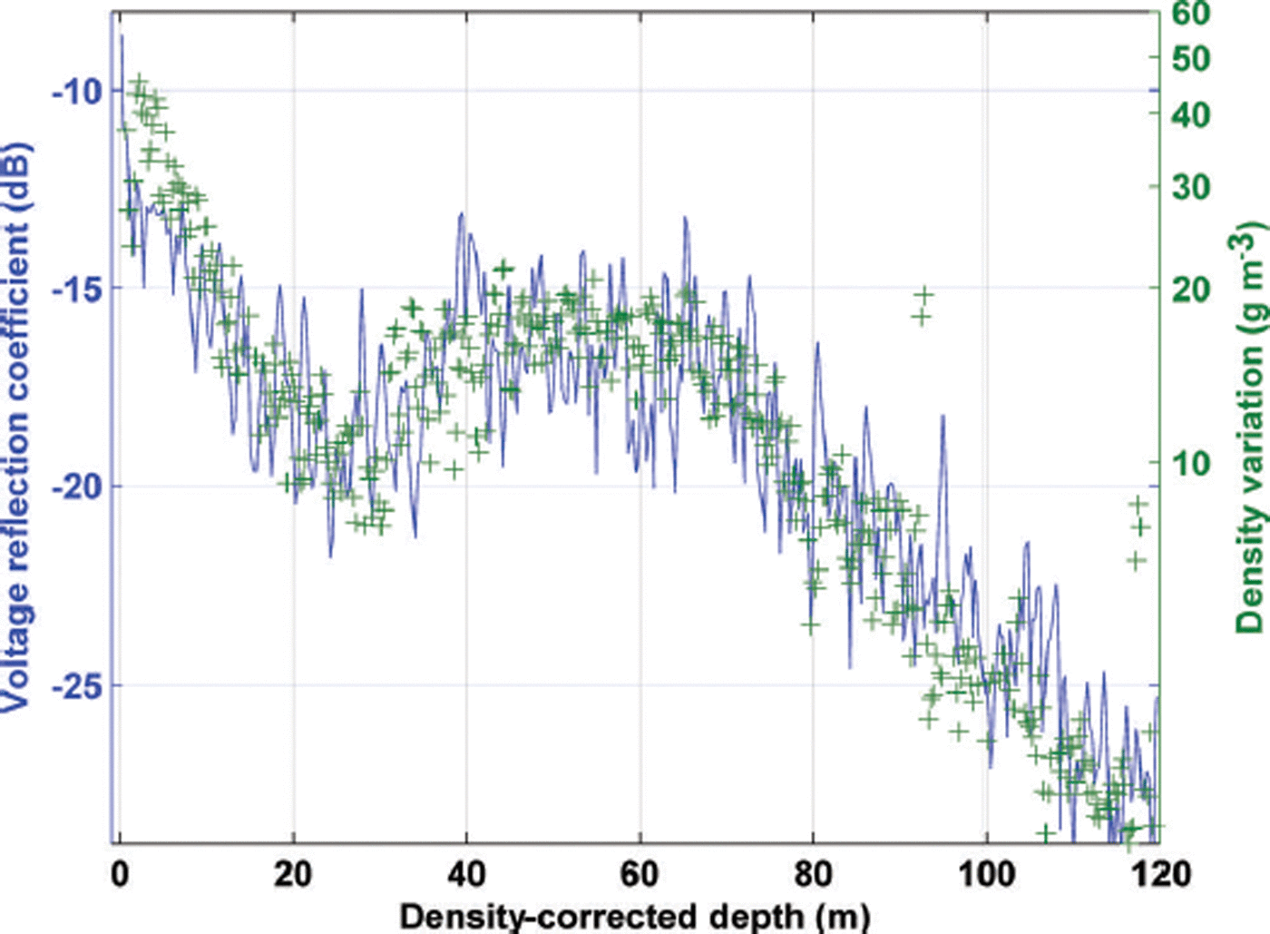
In theory, the radar data can be used to derive an expected relative voltage reflection coefficient profile with depth and compared to a reflection coefficient profile derived from the permittivity profile of an ice core. In practice, this direct comparison is difficult to achieve. In a few areas, the resolution of available core data can be two orders of magnitude finer than the radar resolution. A particular layer echo in the radar data may be a combined response of multiple variations that fall within the radar resolution (Reference HarrisonHarrison, 1973; Reference GudmandsenGudmandsen, 1975). Reference HarrisonHarrison (1973) introduced a statistical approach for estimating the magnitude of the layer reflection coefficient. For a qualitative analysis, we compared the variance of the fine-resolution ice-core permittivity profile with the radar-derived reflection coefficients and found a positive correlation. As all of the interfacial two-way transmission coefficients are near unity, this result was expected. This means that each reflective horizon is receiving nearly the same incident energy; therefore, the shape of the reflectivity profile is tied to a variation in a physical parameter of the medium and is not simply a result of progressive incident energy loss. The dispersion of the permittivity profile is proportional to the potential reflection coefficient derived from it. A relatively large standard deviation implies a higher probability that neighboring permittivity measurements will have a large difference and therefore a large reflection coefficient, while a relatively small standard deviation implies a higher probability that neighboring permittivity measurements will have a small difference and therefore a small reflection coefficient.
In Figure 10 we plot the standard deviation of the Greenland B26 ice core (Reference Miller and SchwagerMiller and Schwager, 2000) with the radar-data-derived reflection coefficients, and scaled them accordingly to highlight their qualitative relationship. We chose the closest available radar return, situated ∼2.1 km from the core site. We calculated the standard deviation using a moving window with a width approximating the resolution of the radar.
Radar-data-derived reflection coefficient compared with the measured B26 ice-core density variation.
We observed three distinct zones within the top 100 m of ice resulting from different firn densification mechanisms. Reference Hörhold, Kipfstuhl, Wilhelms, Freitag and FrenzelHörhold and others (2011), Reference Herron and LangwayHerron and Langway (1980) and Reference BretonBreton (2011) discuss these mechanisms in detail; we discuss them here briefly. The first zone occurs between the surface and the inflection point in the density standard deviation at a depth of ∼25 m. Densities at the inflection point are ∼550 kg m−3 (Reference Herron and LangwayHerron and Langway, 1980; Reference BretonBreton, 2011). Random grain settling is the dominant densification mechanism (Reference Herron and LangwayHerron and Langway, 1980; Reference BretonBreton, 2011; Reference Hörhold, Kipfstuhl, Wilhelms, Freitag and FrenzelHörhold and others, 2011). High-density variability resulting from seasonal changes in the crystal structure of accumulating snow is observed near the surface (Reference Hörhold, Kipfstuhl, Wilhelms, Freitag and FrenzelHörhold and others, 2011). Layers of different densities compact at different rates, with low-density layers compacting faster than high-density layers. This leads to a sharp decrease in the density variability to the minimum, where the layers have nearly the same density (Reference Hörhold, Kipfstuhl, Wilhelms, Freitag and FrenzelHörhold and others, 2011). The second zone occurs between the density variability inflection point and the point of pore close-off. Densities at pore close-off, which occurs at a depth of ∼80 m, are ∼830 kg m−3 (Reference Herron and LangwayHerron and Langway, 1980). A crossover in compaction rates is observed with low-density layers now compacting slower than high-density layers. This leads to a zone of higher density variability (Reference Hörhold, Kipfstuhl, Wilhelms, Freitag and FrenzelHörhold and others, 2011) and subsequently a rise in the layer reflection coefficients in this zone. Interparticle bond growth and particle deformation are the dominating densification mechanisms in the upper portion of the second zone, generally in the density range 550–730 kg m−3 (Reference BretonBreton, 2011). Particle deformation alone dominates densification in the lower portion of the second zone, generally in the density range 730–830 kg m−3 (Reference BretonBreton, 2011). The third zone occurs below pore close-off, where air pore compression is the dominant densification mechanism (Reference Herron and LangwayHerron and Langway, 1980). Density variability quickly decreases with depth as firn densities asymptotically approach that of pure ice. At this point, changes in the loss tangent begin to take over as the dominant mechanism for reflective interfaces.
Radio-Wave Attenuation Rates
For radar reflections from below the surface, we must consider signal extinction through the medium. A review of the literature found that absorption is the dominating extinction factor, and values of ∼19 dB km−1 are expected for our frequencies of operation at ice temperatures of −20°C (Reference GoodmanGoodman, 1975; Reference Paden, Allen, Gogineni, Jezek, Dahl-Jensen and LarsenPaden and others, 2005; Reference Jacobel, Welch, Osterhouse, Pettersson and MacGregorJacobel and others, 2009), a reasonable assumption for cold ice in the interior regions of the ice sheet. We further investigated attenuation rates through ice by analyzing data we collected over ice shelves, ice caps and shallow glaciers. We calculated the depth-averaged attenuation by taking the ratio of the received power between the surface reflection and the basal reflection where the attenuation, L, is the unknown component of the basal reflection received power. Solving for this loss, we get

where P S and P B are the received powers from the surface and basal reflections, ΓS and ΓB are the reflection coefficients of the surface and basal interfaces, and R S and R B are the ranges from the platform to the surface and basal interfaces, respectively.
We calculated the attenuation rate for the Petermann Glacier ice shelf, northwestern Greenland. Figure 11 shows a radargram of the Petermann Glacier ice shelf. A representative trace from near the terminus shows the relative amplitudes of the surface and basal reflections. The diamond marker at 80.9°N, 61.2°W in Figure 4 indicates the approximate location of this radargram. These data were collected aboard the NASA P-3 during the spring 2013 OIB season. Photographic imagery from the OIB Digital Mapping System (DMS) (Reference DominguezDominguez, 2014) collected in concert with our radar data showed a snow-covered surface. We further investigated data collected by the CReSIS snow radar (Reference PanzerPanzer and others, 2013), also collected in concert with our radar data, which revealed that the snow-cover thickness was typically less than the resolution of our radar and therefore unresolvable from the much denser ice below it. The density of this surface ‘interface’ should fall between that of the snow (0.3 kg m−3) and solid ice (0.92 kg m−3), trending toward the higher value. For our calculations, we assumed an average surface interface density of 0.7 kg m−3, which agreed well with our link budget analysis. This corresponds to a dielectric constant of 2.5. An ice/water reflection coefficient was used for the basal return. We found that the depth-averaged attenuation rate varied between 4.3 and 5.6 dB km−1, with higher attenuation rates near the terminus and lower attenuation rates upstream.
Radargram of the Petermann Glacier ice-shelf transect. A representative trace from near the terminus is provided.

We calculated the attenuation rate for two locations on the Ross Ice Shelf, West Antarctica. The first location is a floating portion of the ice shelf approximately halfway between the Pegasus runway and the Antarctic Geological Drilling (ANDRILL) site. Figure 12 shows a radargram of the Ross Ice Shelf at this location. A representative trace shows the relative amplitudes of the surface and basal reflections. Figure 13 provides an enlarged view of the top 50 m to highlight the firn layering. The diamond marker at 77.6°S, 171.6°E in Figure 5 indicates the approximate location of this radargram. These data were collected aboard the Twin Otter during the 2009/10 Antarctic season. We assumed an average surface density of 0.7 kg m−3 (Reference Blaisdell, Klokov and DiemandBlaisdell and others, 1992; Reference ArconeArcone, 1996) and an ice/water basal interface. We found the average attenuation rate to be 16.4 dB km−1. This value compares well with other reported attenuation rates for the Ross Ice Shelf (Reference Bentley, Lord and LiuBentley and others, 1998; Reference Peters, Blankenship and MorsePeters and others, 2005; Reference MacGregor, Winebrenner, Conway, Matsuoka, Mayewski and ClowMacGregor and others, 2007).
Radargram of a Ross Ice Shelf transect located approximately halfway between the Pegasus runway and the ANDRILL site. A representative trace is provided.

Enlarged portion of Ross Ice Shelf radargram to highlight firn layering.

The second location is a grounded portion of the Ross Ice Shelf near the base of Mulock Glacier. Figure 14 shows a radargram of the Ross Ice Shelf at this location. A representative trace shows the relative amplitudes of the surface and basal reflections. The diamond marker at 79.5° S, 163.2° E in Figure 5 indicates the approximate location of this radargram. These data were collected aboard the Twin Otter during the 2011/12 Antarctic season. Again, we assumed an average surface density of 0.7 kg m−3. Granite rock and granite till are the reported bedrock conditions across many regions of Antarctica (Reference Gow, Ueda and GarfieldGow and others, 1968). We assumed an average bedrock dielectric constant of 6 (Reference Davis and AnnanDavis and Annan, 1989; Reference DanielsDaniels, 1996; Reference ZirizzottiZirizzotti and others, 2010) for our reflection coefficient calculations. We investigated traces where there appeared to be a flat and level bedrock interface, indicated by a strong specular return. We found the average attenuation rate to be 16.3 dB km−1.
Radargram of a grounded portion of the Ross Ice Shelf located near the base of Mulock Glacier. A representative trace is provided.

We also investigated attenuation rates through ice caps. Figure 15 shows a radargram of data collected along the western edge of Devon Ice Cap, Nunavut, Canada. The diamond marker at 75.1° N, 84.4° W in Figure 4 indicates the approximate location of this radargram. We corrected the radargram for platform elevation, but did not artificially flatten it to preserve the appearance of the topography. False echoes seen below the bedrock are attributed to pulse resonance caused by strong returns. Overlapping features, as seen on the far right-hand side of the radargram, are likely a result of a combination of off-nadir targets captured by the wide antenna beam width and pulse resonance of those returns from exposed bedrock. Significant near-surface banding may be attributed to varying degrees of summer melting, as reported by Reference ClarkClark and others (2007). Again, we investigated traces where there appeared to be a flat and level bedrock interface, indicated by a strong specular return. We assumed an average surface density of 0.5 kg m−3 (Reference ClarkClark and others, 2007) and a bedrock dielectric constant of 6. We found the average attenuation rate to be 6.6 dB km−1.
Radargram from along the western edge of Devon Ice Cap. A representative trace is provided.

Conclusions
The ability to image deep englacial horizons, and in some instances even firn horizons, is dependent on ice temperature and surface scattering. Ice attenuation rates are highly temperature-dependent. All observed deep reflections were recorded in the northern and central interior regions of the ice sheet, where the ice is sufficiently cold. We often observed a steady drop in recorded interface reflectivity along flight lines traveling from the interior of the ice sheet toward the edge. We also observed a lack of deep reflections in southern interior Greenland. Scattering mechanisms, such as the rough and heavily crevassed surfaces of glaciers and their catchments, also reduced the ability to image deep interfaces. Interface imaging may also be a function of aircraft pitch and is therefore related to the along-track antenna beam width, as layering often disappears during periods of significant pitching maneuvers. For example, during level flight on Petermann Glacier, the rough surface of the floating ice shelf still revealed firn layering, but this layering disappeared during the climb up the glacier, which was marked by significant aircraft pitching. The presence of liquid water, either on the surface or at depth, severely limits or impedes the retrieval of deeper reflections. However, this does provide an opportunity to use the radar and its data for the purpose of detecting liquid water, as reported by Reference Rodriguez-MoralesRodriguez-Morales and others (2013) and Reference ForsterForster and others (2014).
We primarily collected data from ideally stratified regions, making it easy to track interfaces across long horizontal distances. However, most of the East Antarctic ice sheet (EAIS) is covered with unconformable stratigraphy (Reference Arcone, Jacobel and HamiltonArcone and others, 2012a,Reference Arcone, Jacobel and Hamiltonb). We presented results collected over the PIG catchment, which exhibited significant undulations and layer pinching. This could give insight into the ability of the radar to map the unconformed horizons within the EAIS. Many of the regions of unconformable stratigraphy have surface undulations, with wavelengths of 2–5 km and amplitudes of 2–8 m (Reference Arcone, Jacobel and HamiltonArcone and others, 2012a,Reference Arcone, Jacobel and Hamiltonb). With surface slopes considerably shallower than those presented in Figure 8, we would not expect the same visibility degradation seen in Figure 8. We expect the radar to perform similarly when imaging the EAIS, resolving interfaces with 55 cm resolution even in the presence of unconformities.
Our analysis shows that radar-data-derived reflectivity profiles can be used to estimate firn density profiles, the thickness of zones with differing compaction mechanisms and the depth of the firn–ice transition. Our analysis was conducted over cold interior regions of the ice sheet, where we can easily calibrate our data using a link budget approach with established ice surface densities and attenuation rates. This analysis approach may give insight into the change in density profiles and compaction mechanisms over short horizontal distances, such as along glacial streams and in regions of unconformities, such as the EAIS.
Accurate estimation of ice attenuation rates is highly dependent on accurate knowledge of the ice and interface properties. We simplified the calculation by finding a single depth-averaged loss between two known interfaces. We have high confidence in the attenuation rates calculated for floating ice shelves, since both the surface and basal interface had flat regions, providing strong specular reflections. Our calculated attenuation rates matched well with other published rates for the Ross Ice Shelf. Two particular parameters presented a challenge to attenuation rate calculation: the reflectivity of the surface interface and the roughness of the basal interface. When possible, we used nearby published surface densities to estimate the surface reflectivity. Where published surface densities were not available, we used our knowledge of the surface properties to estimate the surface reflectivity. We verified our estimates with a link budget analysis. We showed that basal interface reflectivity is dependent on the interface slope. Finding areas that are sufficiently flat within the radar footprint can prove difficult in regions featuring glacial streams, where ice movement roughens the bedrock, or ice shelves, where the basal interface is characterized by blocks of ice of varying thicknesses, as is the case with Petermann Glacier. Using an antenna array that generates a smaller ground footprint will improve the accuracy of both interface depth and reflectivity estimations, thereby further improving attenuation rate calculations.
Acknowledgements
This work was completed with funding from the US National Science Foundation under grant ANT-0424589 and from NASA under grant NNX10AT68G. We acknowledge the support provided by J. Collins in editing and formatting the manuscript.


 Open access