


1. Introduction
The development of wearable robotic devices has advanced in the past few decades and significantly impacted rehabilitation, assistance, and augmentation. There has been much improvement in the design of wearable devices in terms of dexterity, ergonomics, weight reduction, improvement in control strategies, and making them more human-centric. Human-centric design is one of the most important aspects of wearable devices, as they must be in close contact with the human body and move along with the joints. Significant advances have been made in the design of upper-limb wearable devices, and testing and validation of such devices continue to be a challenge since they are validated directly on human arms to assess their effectiveness and compatibility (Ding et al., Reference Ding, Francisco, Li and Yu2023; Nasr et al., Reference Nasr, Hunter, Dickerson and McPhee2023; Atkins et al., Reference Atkins, Chang and Lee2024). Safety of the subjects and ethical and legal issues have dominated the field. The human upper limb is a complex serial chain of bones having synovial joints with ligaments and tendons holding each joint together, adding compliance to the joint where the muscles actuate each joint. Shoulder joints are the most important when considering the upper limb, as they provide flexibility and dexterity to the arm. The inner shoulder joint is the base joint of the upper limb formed by the shoulder girdle (SG), having three degrees of freedom (DOF) with a limited range of motion (ROM). The outer shoulder joint, also known as the glenohumeral (GH) joint, provides maximum mobility to the arm. Direct testing of exoskeletons on a human arm can cause adverse effects on the user, such as damage or straining in specific joint components due to different reasons, such as misalignment between the human and exoskeleton joint, improper collaborative motion, and uneven balancing of the weight of the device. To ensure safety and compliance, exoskeletons need to be initially tested on an upper limb phantom with anatomically similar motion to a human upper limb. These tests are used to measure the reachable workspace, interaction forces exerted by the exoskeleton due to joint misalignment, and identify potential safety issues. Many upper limb manipulators are available in the literature and are used as humanoid phantoms for testing exoskeletons (Paik et al., Reference Paik, Shin, Bang and Shim2012; Asfour et al., Reference Asfour, Schill, Peters, Klas, Bücker, Sander, Schulz, Kargov, Werner and Bartenbach2013; Mick et al., Reference Mick, Lapeyre, Rouanet, Halgand, Benois-Pineau, Paclet, Cattaert, Oudeyer and de Rugy2019; Dou et al., Reference Dou, Yu, Li, Chen, Xia, Zhai, Yokoi and Jiang2022). In most phantoms, shoulder joints have three revolute joints to mimic the GH joint’s abduction/adduction, flexion/extension, and internal/external rotation. However, they fail to mimic the human shoulder motion entirely because most of the rotations of these phantom shoulders happen at a fixed center of rotation. The three revolute motions are achieved using three mutually perpendicular actuators that mimic the motion of the arm. Still, they are unsuitable for testing wearable devices because of their differences from human anatomical motion. The other types of shoulder mechanisms in literature have parallel configurations with fixed centers of rotation, actuated either by linear actuators or are cable-driven, and the complete mechanism represents a spherical joint (Okadome et al., Reference Okadome, Nakamura, Urai, Nakata and Ishiguro2015; Otarbay et al., Reference Otarbay, Yessirkepov, Ishuov and Folgheraiter2021; Yang et al., Reference Yang, Chen, Ding, Wu, Zhang and Yang2023). These joint mechanisms fail to mimic joint compliance and cannot measure the interaction forces arising due to joint misalignment between the human shoulder and the exoskeleton mechanism. To introduce compliance to a joint with three mutually perpendicular actuations, Li et al. (Reference Li, Kim, Park, Choi, Lu and Peng2022) developed a tensegrity structure mimicking the three shoulder motions, where the joints are stabilized using fixed cables. Due to the fixed nature of the cables, this shoulder mechanism fails to replicate humeral head translation and is, therefore, unsuitable for testing interaction forces. Similarly, Li et al. (Reference Li, Wang, Togo, Yokoi and Jiang2021) devised a coupled tendon-driven shoulder joint mechanism that achieves the three major human-like motions. This mechanism features a moving center of rotation revolving around another joint center. Yet, it does not mimic humeral head translation and is inadequate for providing interaction force feedback when integrated with an exoskeleton (Li et al., Reference Li, Wang, Togo, Yokoi and Jiang2021). Mouthuy et al. developed a humanoid shoulder joint with a ball-and-socket arrangement utilizing bioreactors to mimic tendinous fibers. However, this design also fails to replicate humeral head translation and cannot be used for exoskeleton testing due to its limitations in providing interactive force feedback (Mouthuy et al., Reference Mouthuy, Snelling, Hostettler, Kharchenko, Salmon, Wainman, Mimpen, Paul and Carr2022). Because of the abovementioned drawbacks, the humanoid shoulder joint mechanisms described in the literature cannot be employed as an exoskeleton test bench. There is no standardized test bench in the market or in the literature that researchers and industrialists use to test exoskeletons, which can provide the proper shoulder anatomical motion. Mostly, they depend on simple linkage mechanisms with joints sufficient to provide motion along a single axis to test the workings of an upper limb exoskeleton. Such test benches lack standardized testing and comparison features such as (i) the capability to be mounted on and test any exoskeleton configuration for its possible maximum ROM in any possible direction; (ii) the measurement of the interaction force between the exoskeleton and the phantom during motion when there is a joint axis misalignment, where the misalignment can be controlled in the phantom; (iii) to test the ergonomics of the exoskeleton so that it can fit different users based on their anthropometric and physical size variations; and (iv) repeatability to perform continuous testing for analyzing the exoskeleton’s capability based on its application. These significant drawbacks in existing humanoid shoulder mechanisms render them unsuitable for testing exoskeletons, as they cannot mimic the human shoulder joint’s rotation with an instantaneous center.
Considering these significant flaws, a one-of-a-kind novel upper limb human shoulder phantom is presented in this article, which mimics the shoulder complex, along with the humeral head translation motion to provide an instantaneous center of rotation to the outer shoulder joint. The proposed phantom has sensors to measure the joint angles and the interaction forces between the phantom and the exoskeleton. This phantom focuses on addressing the abovementioned drawbacks in exoskeleton testing and comparison by being a device that can be used for standardized and repeatable testing and evaluation of exoskeletons before proceeding to human trials. The following sections explain the design of the shoulder phantom, including the link length selection based on anthropometric data, kinematics, the joint spring selection, and the static structural simulation. In addition to the design details, the selection of actuators and sensors, sensor calibration, prototyping, and experimentation with the shoulder phantom to perform arm elevation are presented.
2. Design of the shoulder phantom
The proposed shoulder phantom, as shown in Figure 1(a), is designed based on the modified human shoulder model proposed in Pramod et al. (Reference Pramod, Mohan and Thondiyath2024a), which considers the humeral head translation from the glenoid fossa of the scapula. The broad design requirements for the phantom have been identified as follows:
-
1. Provide joint motions similar to the human shoulder, including the SG and GH joint motion.
-
2. GH mechanism with motions similar to the humeral head rotation and translation, having joint angle and linear translation feedback with a compact, controllable linear translating mechanism.
-
3. Structural similarity is needed to accommodate different size ranges of human shoulder and bicep attachments for testing the upper limb exoskeletons.
-
4. Capability for joint angle sensing and three-dimensional interaction force measurement between the shoulder phantom and the attached exoskeleton.
(a) Computer-Aided Design (CAD) model of the shoulder phantom with frame assignment and (b) exploded view of the phantom with subassemblies.
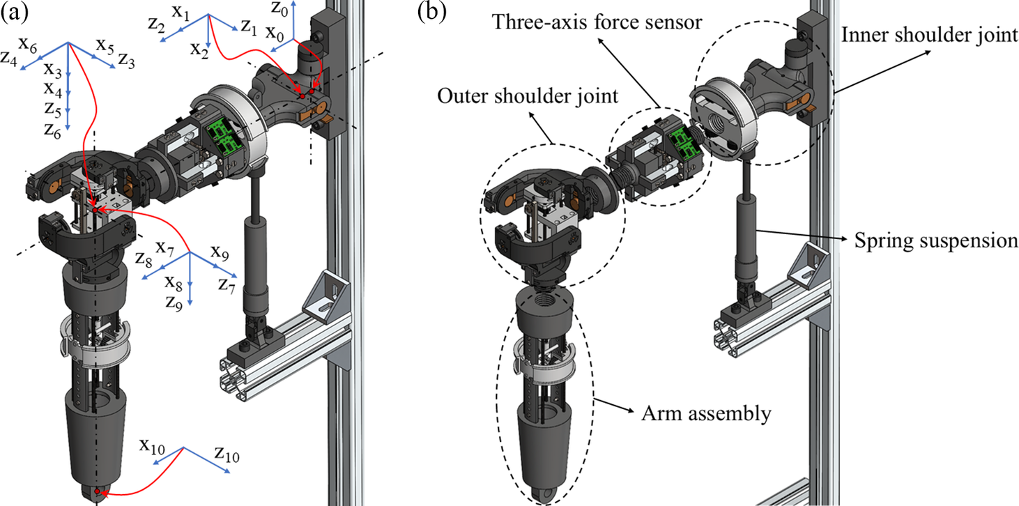
Based on the design requirements, the proposed phantom design has four subassemblies, as shown in Figure 1(b). The first subassembly is the inner shoulder joint, which represents the SG mechanism, whose one end is attached to the fixed stand and the other end is connected to the second subassembly, which is a three-axis force sensor. The other end of the force sensor is attached to the outer shoulder joint assembly, representing the GH joint mechanism to which the fourth subassembly is attached. The fourth subassembly is the arm assembly, representing a human arm to which one end of the exoskeleton can be connected. The phantom is designed to have passive joints with sensors that can measure the rotational angle, and an active prismatic joint mimics the humeral head translation (Pramod et al., Reference Pramod, Thondiyath and Mohan2024b). The detailed design of each subassembly is given in Figure 2.
-
i. SG assembly
As shown in Figure 2(a), the SG assembly provides joint motions similar to the human SG motion. It has a universal-prismatic configuration for mimicking the retraction/protraction, elevation/depression, and contraction/extension motion. The two passive revolute joints $ {R}_{SG1} $
and
$ {R}_{SG2} $
are incorporated with joint angle sensors, and together they form a universal joint and
$ {P}_{SG1} $
is the passive prismatic joint. The SG assembly has an expandable shoulder attachment whose diameter is varied using two pairs of size-adjustable knobs utilizing the screw joint, and this size-variable feature mimics the varying size of the human shoulder for attaching the exoskeleton.Figure 2.
$ {R}_{SG1} $
and
$ {R}_{SG2} $
are incorporated with joint angle sensors, and together they form a universal joint and
$ {P}_{SG1} $
is the passive prismatic joint. The SG assembly has an expandable shoulder attachment whose diameter is varied using two pairs of size-adjustable knobs utilizing the screw joint, and this size-variable feature mimics the varying size of the human shoulder for attaching the exoskeleton.Figure 2.(a) SG assembly, (b) three-axis force sensor assembly, (c) GH assembly, and (d) arm assembly.


-
ii. GH joint assembly
As shown in Figure 2(c), the GH assembly provides joint motions similar to the human GH joint motion. It has a spherical–prismatic–spherical (SPS) configuration, where the prismatic joint separating the two spherical joints is active. Here, the second spherical joint mimics the flexion/extension, abduction/adduction, and external/internal rotation motion of the arm, and the prismatic joint mimics the translation of the humeral head due to tendon and ligament stretching. The first spherical joint facilitates the three-dimensional translation of the second spherical joint. The passive revolute joints
$ {R}_1 $
,
$ {R}_2 $
, and
$ {R}_3 $
form the first spherical joint,
$ {R}_4 $
,
$ {R}_5 $
, and
$ {R}_6 $
form the second spherical joint, and
$ {P}_1 $
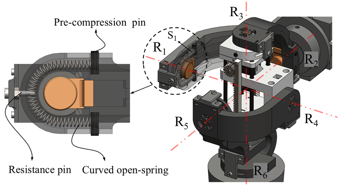
is the active prismatic joint. The spherically curved links are used to form the revolute joints, which constrain the whole GH mechanism within an imaginary sphere. The revolute joints between two subsequent spherical links of the GH assembly are formed by shrunk-fitting a cylindrical projection on one end of the link to a bearing on the other link. The SPS configuration of the GH assembly has seven joints, constituting seven DOF, making the system kinematically redundant. All the passive joints are incorporated with a curved spring, and a resistance pin is set up to prevent the collapse of the mechanism due to self-weight. Both spherical joints have three sensor-incorporated revolute joints each. The active prismatic joint is a sliding mechanism actuated by a pair of micro servomotors using a rack and pinion transmission for each motor. The linear translation of
$ {P}_1 $
is measured using a displacement sensor attached to the mechanism.


-
iii. Arm assembly
The arm assembly, as shown in Figure 2(d), mimics the human upper arm; it has an expandable arm attachment whose diameter is varied using a pair of size-adjustable knobs utilizing the screw joint. The arm attachment can also be varied by sliding along the guides to adjust the attachment length along the arm assembly. This size-variable feature mimics the varying size of the human upper arm for attaching the exoskeleton. The arm assembly is also designed to attach the forearm and hand assembly for the complete upper limb exoskeleton attachment and testing.
-
iv. Three-axis force sensor
As shown in Figure 2(b), a three-axis force sensor module is designed to measure the interaction forces between the exoskeleton and the shoulder phantom. This can be attached between the SG and the GH assembly and can measure forces in five directions (positive x, y axes and negative x, y, z axes) using the force sensor slider, which comes in contact with the load cells mounted on the force sensor base. The sensor slider is attached to the GH assembly, and the sensor base is connected to the SG assembly. The load cells are mechanically fastened to the base using nuts and bolts, and the force sensor slider is constrained between the load cells.
The shoulder phantom design facilitates the attachment of the exoskeleton at the shoulder attachment of the SG assembly and the arm attachment of the arm assembly. These two attachments help isolate the GH joint mechanism while testing the exoskeleton for misalignment due to humeral head translation. The misalignment between the exoskeleton and phantom joint axis is identified by measuring the interaction forces using a three-axis force sensor module attached between the SG and the GH joint assembly. Since the exoskeleton needs to be tested on a phantom before testing it on a human body, the phantom should mimic the human shoulder motion and has dimensions proportional to that of a human. Inevitable design trade-offs have been made to accomplish the aforementioned design goals. For example, the straightforward three-axis GH joint technique that is currently employed in humanoid shoulder joints in the literature has been modified to a more complex seven DOF joint mechanism to match the human-like motion. This raises the complexity to fit the entire system inside the necessary dimensions. The phantom is designed such that it can be scaled based on the level of its practical application, and individual components may be manufactured quickly and affordably using injection molding or rapid prototyping rather than going for a conventional machining technique, which might not be an ideal option, as the parts have intricate features.
2.1. Shoulder-phantom proportion
Primarily, the exoskeletons are designed and developed considering the average size of a human body so that the fit is made proper by adjusting the attachments for the user with smaller or larger sizes from the average size up to a particular range. The shoulder phantom is also designed considering this change in human shoulder dimensions. For a male human body, the average humerus length ( $ {L}_{H\_ Avg}\Big) $
is 304.56 ± 14.16 mm, average scapular length (
$ {L}_{H\_ Avg}\Big) $
is 304.56 ± 14.16 mm, average scapular length ( $ {L}_{S\_ Avg}\Big) $
is 148.9 ± 13.6 mm, and the average humeral head diameter (
$ {L}_{S\_ Avg}\Big) $
is 148.9 ± 13.6 mm, and the average humeral head diameter ( $ {D}_{HH\_ Avg}\Big) $
is 49.9 ± 3.3 mm. These are taken as the benchmark values for the design (Jacobson et al., Reference Jacobson, Gilot, Greene, Flurin, Wright, Zuckerman and Roche2015; Khan et al., Reference Khan, Gul and Nizami2020; Elijah et al., Reference Elijah, Peter, Ekanem and Edagha2021). The dimensions from the joint to the exoskeleton attachment positions are chosen based on these benchmarks, where the GH joint mechanism of the phantom is limited within an imaginary sphere of diameter 160 mm by assuming the thickness of the shoulder muscles surrounding the GH joint to be twice that of
$ {D}_{HH\_ Avg}\Big) $
is 49.9 ± 3.3 mm. These are taken as the benchmark values for the design (Jacobson et al., Reference Jacobson, Gilot, Greene, Flurin, Wright, Zuckerman and Roche2015; Khan et al., Reference Khan, Gul and Nizami2020; Elijah et al., Reference Elijah, Peter, Ekanem and Edagha2021). The dimensions from the joint to the exoskeleton attachment positions are chosen based on these benchmarks, where the GH joint mechanism of the phantom is limited within an imaginary sphere of diameter 160 mm by assuming the thickness of the shoulder muscles surrounding the GH joint to be twice that of $ {D}_{HH\_ Avg}. $
The sensor incorporated spherical links (links having a curved shape to fit the circumference of a sphere), forming the two spherical joints, and an active prismatic joint was designed to be within this sphere. This arrangement does not obstruct the required range of individual revolute joint angles.
$ {D}_{HH\_ Avg}. $
The sensor incorporated spherical links (links having a curved shape to fit the circumference of a sphere), forming the two spherical joints, and an active prismatic joint was designed to be within this sphere. This arrangement does not obstruct the required range of individual revolute joint angles.
Each link has a thickness to withstand the loading conditions during its function, which is determined based on the static structural analysis of the system, discussed in the following sections. Therefore, the average diameter of the humerus attachment, $ {D}_{HA\_ Avg} $
, is taken as 100 mm, and the average diameter of the shoulder attachment,
$ {D}_{HA\_ Avg} $
, is taken as 100 mm, and the average diameter of the shoulder attachment, $ {D}_{SA\_ Avg} $
, is taken as 160 mm. Similarly, considering the exoskeleton attachment position to be at a distance from the joints, the average length of the humerus attachment from the GH joint (
$ {D}_{SA\_ Avg} $
, is taken as 160 mm. Similarly, considering the exoskeleton attachment position to be at a distance from the joints, the average length of the humerus attachment from the GH joint ( $ {L}_{HA\_ Avg}\Big) $
is taken as 205 mm and the average length of the shoulder attachment from the first revolute joint in the SG mechanism (
$ {L}_{HA\_ Avg}\Big) $
is taken as 205 mm and the average length of the shoulder attachment from the first revolute joint in the SG mechanism ( $ {L}_{SA\_ Avg} $
) is taken as 150 mm. Considering the variations in the distance between the joints and circumferential thickness around the shoulder and arm in the human body, an adjustable range of
$ {L}_{SA\_ Avg} $
) is taken as 150 mm. Considering the variations in the distance between the joints and circumferential thickness around the shoulder and arm in the human body, an adjustable range of $ {L}_{HA} $
and
$ {L}_{HA} $
and $ {L}_{SA} $
is provided with
$ {L}_{SA} $
is provided with $ 160\;\mathrm{mm}<{L}_{HA\_ Avg}<250\;\mathrm{mm} $
and
$ 160\;\mathrm{mm}<{L}_{HA\_ Avg}<250\;\mathrm{mm} $
and $ 140\;\mathrm{mm}<{L}_{SA\_ Avg}<160\;\mathrm{mm}, $
respectively, as shown in Figure 3.
$ 140\;\mathrm{mm}<{L}_{SA\_ Avg}<160\;\mathrm{mm}, $
respectively, as shown in Figure 3.
(a) $ {L}_H<{L}_{H\_ Avg} $
,
$ {L}_H<{L}_{H\_ Avg} $
, $ {L}_S<{L}_{S\_ Avg} $
; (b)
$ {L}_S<{L}_{S\_ Avg} $
; (b) $ {L}_H>{L}_{H\_ Avg} $
,
$ {L}_H>{L}_{H\_ Avg} $
, $ {L}_S>{L}_{S\_ Avg} $
; (c)
$ {L}_S>{L}_{S\_ Avg} $
; (c) $ {D}_H<{D}_{HH\_ Avg} $
,
$ {D}_H<{D}_{HH\_ Avg} $
, $ {D}_S<{D}_{SA\_ Avg} $
; and (d)
$ {D}_S<{D}_{SA\_ Avg} $
; and (d) $ {D}_H>{D}_{HH\_ Avg} $
,
$ {D}_H>{D}_{HH\_ Avg} $
, $ {D}_S>{D}_{SA\_ Avg} $
, where
$ {D}_S>{D}_{SA\_ Avg} $
, where $ {L}_H $
and
$ {L}_H $
and $ {L}_S $
are the humerus and scapular length, respectively, and
$ {L}_S $
are the humerus and scapular length, respectively, and $ {D}_H $
and
$ {D}_H $
and $ {D}_S $
are the humerus and shoulder attachment diameters, respectively.
$ {D}_S $
are the humerus and shoulder attachment diameters, respectively.
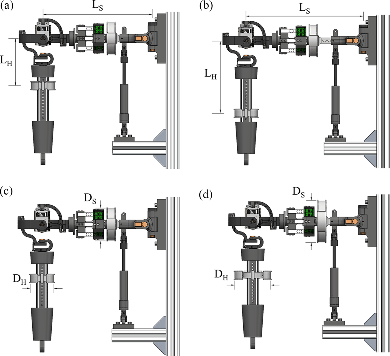
Similarly, the range of arm attachment diameter and the shoulder attachment diameter are kept to be $ 80\;\mathrm{mm}<{D}_{H\_ Avg}<120\;\mathrm{mm} $
and
$ 80\;\mathrm{mm}<{D}_{H\_ Avg}<120\;\mathrm{mm} $
and $ 140\;\mathrm{mm}<{D}_{SA\_ Avg}<180\;\mathrm{mm} $
, respectively. The
$ 140\;\mathrm{mm}<{D}_{SA\_ Avg}<180\;\mathrm{mm} $
, respectively. The $ {L}_H $
is varied by sliding the arm attachment along the length of the slider guide and
$ {L}_H $
is varied by sliding the arm attachment along the length of the slider guide and $ {L}_S $
is varied using the passive joint
$ {L}_S $
is varied using the passive joint $ {P}_{SG1} $
. Based on the range of humeral head translation in humans, the active prismatic joint mechanism within the GH joint mechanism is designed to provide a translation of 18 mm. This flexibility in changing the range of dimensions of the phantom helps to mimic different shoulder anthropometric features and proportions.
$ {P}_{SG1} $
. Based on the range of humeral head translation in humans, the active prismatic joint mechanism within the GH joint mechanism is designed to provide a translation of 18 mm. This flexibility in changing the range of dimensions of the phantom helps to mimic different shoulder anthropometric features and proportions.
2.2. Reachable workspace
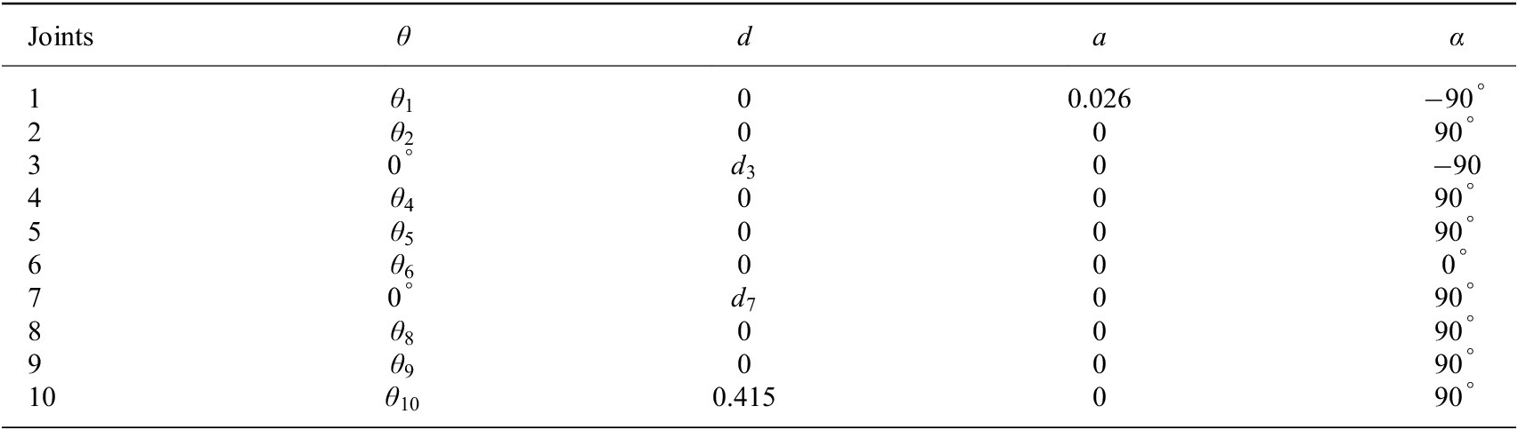
The reachable workspace of the phantom can be computed using the forward kinematics of the arm subassembly. The orientation and position of the tip of the arm subassembly with respect to the first revolute joint of the SG subassembly is found by transforming the frames assigned to each joint based on the Denavit–Hartenberg (DH) method (Denavit and Hartenberg, Reference Denavit and Hartenberg1955), as shown in Figure 1(a). After frame transformation, the DH parameters are obtained as in Table 1, where θ, d, a, and α are the link and joint parameters, respectively. Here, $ {d}_3 $
,
$ {d}_3 $
, $ {d}_7 $
, and
$ {d}_7 $
, and $ {d}_{10} $
represent the GH translation due to SG motion along
$ {d}_{10} $
represent the GH translation due to SG motion along $ {Z}_2 $
axis, the humeral head translation along
$ {Z}_2 $
axis, the humeral head translation along $ {Z}_6 $
axis, and the joint offset of the tip of the arm subassembly, respectively. The parameter
$ {Z}_6 $
axis, and the joint offset of the tip of the arm subassembly, respectively. The parameter $ {a}_1 $
represents the link distance between the two revolute joints of the SG subassembly.
$ {a}_1 $
represents the link distance between the two revolute joints of the SG subassembly.
DH parameters
The transformation equation between two frames using the DH parameters is given as,
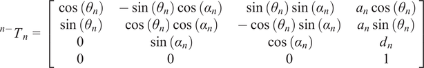 $$ {}^{n-}{T}_n=\left[\begin{array}{cccc}\cos \left({\theta}_n\right)& -\sin \left({\theta}_n\right)\cos \left({\alpha}_n\right)& \sin \left({\theta}_n\right)\sin \left({\alpha}_n\right)& {a}_n\cos \left({\theta}_n\right)\\ {}\sin \left({\theta}_n\right)& \cos \left({\theta}_n\right)\cos \left({\alpha}_n\right)& -\cos \left({\theta}_n\right)\sin \left({\alpha}_n\right)& {a}_n\sin \left({\theta}_n\right)\\ {}0& \sin \left({\alpha}_n\right)& \cos \left({\alpha}_n\right)& {d}_n\\ {}0& 0& 0& 1\end{array}\right] $$
The transformation matrix $ {}^0{T}_{10} $
in Equation (2) represents the position and orientation of the tip of the arm subassembly as a function of the 10 joint variables
$ {}^0{T}_{10} $
in Equation (2) represents the position and orientation of the tip of the arm subassembly as a function of the 10 joint variables $ {\theta}_1 $
,
$ {\theta}_1 $
, $ {\theta}_2 $
,
$ {\theta}_2 $
, $ {d}_3 $
,
$ {d}_3 $
, $ {\theta}_4 $
,
$ {\theta}_4 $
, $ {\theta}_5 $
,
$ {\theta}_5 $
, $ {\theta}_6 $
,
$ {\theta}_6 $
, $ {d}_7 $
,
$ {d}_7 $
, $ {\theta}_8 $
,
$ {\theta}_8 $
, $ {\theta}_9 $
, and
$ {\theta}_9 $
, and $ {\theta}_{10} $
with respect to the first revolute joint of the SG subassembly.
$ {\theta}_{10} $
with respect to the first revolute joint of the SG subassembly.
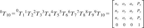 $$ {\displaystyle \begin{array}{c}{}^0{T}_{10}={}^0{T}_1{}^1{T}_2{}^2{T}_3{}^3{T}_4{}^4{T}_5{}^5{T}_6{}^6{T}_7{}^7{T}_8{}^8{T}_9{}^9{T}_{10}=\left[\begin{array}{cccc}{n}_x& {o}_x& {a}_x& {P}_x\\ {}{n}_y& {o}_y& {a}_y& {P}_y\\ {}{n}_z& {o}_z& {a}_z& {P}_z\\ {}0& 0& 0& 1\end{array}\right]\end{array}} $$
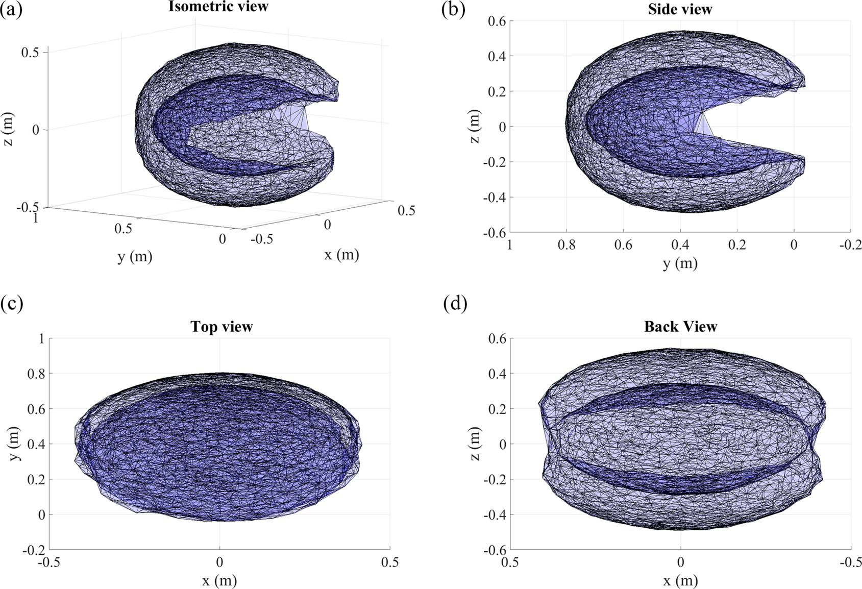
From the forward kinematics Equation (2), the maximum and the minimum reachable work envelope achievable by the shoulder phantom is plotted. The Monte Carlo method is used to plot the work envelope, as shown in Figure 4; the joint and link parameters based on the phantom design are the input parameters and are given in Table 1. The region in light blue color within the work envelope represents the possible reachable positions of the phantom arm tip, and the darker region indicates the positions where the tip cannot reach. The workspace volume is obtained as $ 0.2292\;{\mathrm{m}}^3 $
, which is the surface volume that fits the plotted marker points. From the workspace, it is identified that the phantom arm can move up to a range of 0°–180° along the horizontal plane and −45° to 225° along the vertical plane. This range is greater than the ROM of the upper limb exoskeletons present in literature (Lee et al., Reference Lee, Kwon, Soltis, Matthews, Lee, Kim, Romero, Zavanelli, Kwon, Kwon, Lee, Yewon, Lee, Yu, Shinohara, Hammond and Yeo2024; Ning et al., Reference Ning, Wang, Liu, Wang, Rong and Niu2024; Pei et al., Reference Pei, Wang, Yang, Dong, Guo, Guo and Yao2024; Shi et al., Reference Shi, Yang, Hou and Yu2024); therefore, the phantom can be used to test the reachable workspace of the upper limb exoskeletons.
$ 0.2292\;{\mathrm{m}}^3 $
, which is the surface volume that fits the plotted marker points. From the workspace, it is identified that the phantom arm can move up to a range of 0°–180° along the horizontal plane and −45° to 225° along the vertical plane. This range is greater than the ROM of the upper limb exoskeletons present in literature (Lee et al., Reference Lee, Kwon, Soltis, Matthews, Lee, Kim, Romero, Zavanelli, Kwon, Kwon, Lee, Yewon, Lee, Yu, Shinohara, Hammond and Yeo2024; Ning et al., Reference Ning, Wang, Liu, Wang, Rong and Niu2024; Pei et al., Reference Pei, Wang, Yang, Dong, Guo, Guo and Yao2024; Shi et al., Reference Shi, Yang, Hou and Yu2024); therefore, the phantom can be used to test the reachable workspace of the upper limb exoskeletons.
(a) Isometric view, (b) side view, (c) top view, and (d) back view of the shoulder phantom workspace.
2.3. Self-collapse prevention
In the GH joint assembly, redundancy in the mechanism can lead to collapse of the whole arm assembly since all the revolute joints are passive and have no active mechanism to keep the links in position. Therefore, to overcome this, a clever arrangement of springs is incorporated within the joints to provide a resistive torque that prevents links from collapsing due to the self-weight of the subassembly, as shown in Figure 5. For the two links forming a joint, one link will have a spring, and the other will have a resistance pin fastened to it; this resistance pin wedges between the coils of the spring in the other link to provide resistive torque when the links are rotated in either direction. All the springs are curved to fit the link slot and are pre-compressed to their required initial stiffness using carbon pins. As shown in Figure 5, for the first spherical joint, the revolute joints $ {R}_1 $
,
$ {R}_1 $
, $ {R}_2 $
, and
$ {R}_2 $
, and $ {R}_3 $
are having the springs
$ {R}_3 $
are having the springs $ {S}_1 $
,
$ {S}_1 $
, $ {S}_2 $
, and
$ {S}_2 $
, and $ {S}_3 $
respectively. Similarly, in the second spherical joint, the revolute joints
$ {S}_3 $
respectively. Similarly, in the second spherical joint, the revolute joints $ {R}_4 $
,
$ {R}_4 $
, $ {R}_5 $
, and
$ {R}_5 $
, and $ {R}_6 $
are having the springs
$ {R}_6 $
are having the springs $ {S}_4 $
,
$ {S}_4 $
, $ {S}_5 $
, and
$ {S}_5 $
, and $ {S}_6 $
, respectively.
$ {S}_6 $
, respectively.
The curved open spring arrangement for each revolute joint in the GH subassembly.
During arm elevation, the human shoulder exhibits a resistive shoulder joint torque, which can be replicated using the same spring setup. In addition, the humeral head must be translated once the arm elevation angle crosses 90°, along with the SG motion (Williamson et al., Reference Williamson, Momenzadeh, Hanna, Abbasian, Kheir, Lechtig, Okajima, Garcia, Ramappa, Nazarian and DeAngelis2023). This is achieved by the translation of the second spherical joint once the first spherical joint has completed its angular motion. To achieve this sequential motion, the springs in the first spherical joint are designed with lower stiffness. The initial resistance in the springs is achieved by pre-compressing, which helps keep the mechanism from collapsing. The springs are designed to hold the assembly’s self-weight; hence, only the first spherical joint is activated during arm elevation. For the second spherical joint, which needs to be activated after the first spherical joint reaches its limit, the initial stiffness before elevation is kept equal to the maximum stiffness attained by the first spherical joint when it is at an angle of 90°. Taking this into account, $ {S}_1 $
,
$ {S}_1 $
, $ {S}_2 $
, and
$ {S}_2 $
, and $ {S}_3 $
are designed for an operating range of 15–50 N. Similarly, in the second spherical joint, the springs
$ {S}_3 $
are designed for an operating range of 15–50 N. Similarly, in the second spherical joint, the springs $ {S}_4 $
,
$ {S}_4 $
, $ {S}_5 $
, and
$ {S}_5 $
, and $ {S}_6 $
are designed for an operating range of 50–70 N.
$ {S}_6 $
are designed for an operating range of 50–70 N.
2.4. Spring design and selection
For ease of computation, the springs are considered straight open coil springs by taking the variation in the helix angle “α” to be negligible. The outer diameter of the spring is set to be 5 mm owing to space constraints of the links, then for wire diameters $ d=\left\{\left.0.5,0.6,0.7,0.8,0.9\;\right\}\right. $
, and for a range of number of coils from 2 to 30, a range of stiffness for individual springs is computed using the spring stiffness equation (Pastorcic et al., Reference Pastorcic, Vukelic and Bozic2019),
$ d=\left\{\left.0.5,0.6,0.7,0.8,0.9\;\right\}\right. $
, and for a range of number of coils from 2 to 30, a range of stiffness for individual springs is computed using the spring stiffness equation (Pastorcic et al., Reference Pastorcic, Vukelic and Bozic2019),
 $$ {\displaystyle \begin{array}{c}k=\frac{G{d}^4}{8n{D}^3}\end{array}} $$
where the material is assumed to be mild steel having a modulus of rigidity G = 79 GPa.
By accounting for the self-weight of the GH joint assembly and the arm assembly, which is ~1,114 g, an initial compression distance for $ {S}_1 $
,
$ {S}_1 $
, $ {S}_2 $
, and
$ {S}_2 $
, and $ {S}_3 $
is calculated for a force of 15 N. Similarly, for the springs
$ {S}_3 $
is calculated for a force of 15 N. Similarly, for the springs $ {S}_4 $
,
$ {S}_4 $
, $ {S}_5 $
, and
$ {S}_5 $
, and $ {S}_6 $
, the initial compression distance for a force of 50 N is calculated based on the final stiffness of the initial set of springs. Finally, taking into account each joint angle limit, the length of the spring that can be accommodated within the links, the feasible spring compressible distance, the fully compressed length, and the resistive force at maximum deflection, the most suitable springs are selected from the commercially available set, as shown in Table 2. The detailed design calculations and selection process are given in Supplementary Material 1.
$ {S}_6 $
, the initial compression distance for a force of 50 N is calculated based on the final stiffness of the initial set of springs. Finally, taking into account each joint angle limit, the length of the spring that can be accommodated within the links, the feasible spring compressible distance, the fully compressed length, and the resistive force at maximum deflection, the most suitable springs are selected from the commercially available set, as shown in Table 2. The detailed design calculations and selection process are given in Supplementary Material 1.
Dimensions of the open coil springs used in the GH subassembly

2.5. Linear actuation mechanism
The humeral head translation within the GH joint is achieved using a micro linear actuation mechanism designed to carry the load of the phantom arm and provide linear actuation during the arm elevation. The linear actuators available in the market are not used because of their limitations in size, load-carrying capacity, limited full load speed, and lack of position feedback. Based on the application, an appropriate design is proposed, as shown in Figure 6, with the actuation provided by two micro digital servomotors and a rack and pinion transmission. The design of the linear actuation mechanism takes into account a length constraint of 80 mm, a stroke length requirement of 20 mm, and position feedback to regulate both the stroke length and position. The motors are attached on either side of the sliding base, sliding along the length of the slider guides, which are a part of the actuator stator. The actuation is achieved when the two pinions (pitch diameter = 12.5 mm and number of teeth = 18) attached to the motors rotate in opposite directions, pushing against the rack (length = 69 mm and number of teeth = 31), making the platform slide through the slider guide rods. The linear actuator is provided with a linear displacement sensor and two limit switches on either end to provide position feedback.
Dual micro servo-actuated linear actuator with rack and pinion transmission.
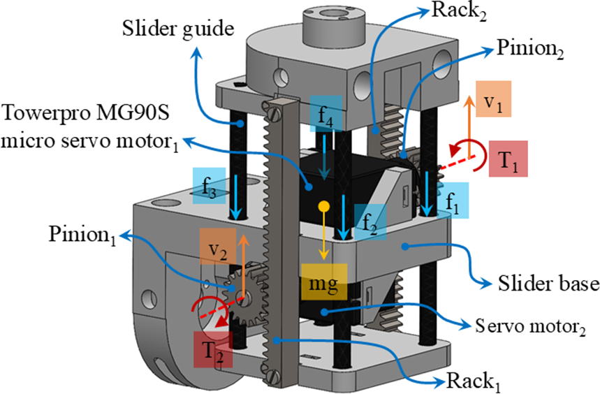
To size the actuators, force equilibrium Equation (4) is used to solve for the load-carrying capacity of the linear actuator.
 $$ {\displaystyle \begin{array}{c}\frac{T_1}{r_1}+\frac{T_2}{r_2}+m\dot{v}= mg+{F}_{friction}\end{array}} $$
Here, $ {T}_1 $
and
$ {T}_1 $
and $ {T}_2 $
are the servomotor torque,
$ {T}_2 $
are the servomotor torque, $ v $
is the translation velocity, and
$ v $
is the translation velocity, and $ m $
is the mass of the sliding part. The friction between the slider base and the sliding guide is given as
$ m $
is the mass of the sliding part. The friction between the slider base and the sliding guide is given as $ {F}_{friction}={\sum}_{i=1}^4{f}_i $
representing the friction in the four slides. In an ideal case,
$ {F}_{friction}={\sum}_{i=1}^4{f}_i $
representing the friction in the four slides. In an ideal case, $ v={v}_1={v}_2 $
. The theoretical maximum stalling load for a uniform velocity of the linear actuator in the ideal case is
$ v={v}_1={v}_2 $
. The theoretical maximum stalling load for a uniform velocity of the linear actuator in the ideal case is $ 3.52\;\mathrm{kg} $
(assuming
$ 3.52\;\mathrm{kg} $
(assuming $ {F}_{friction}=0 $
). Based on this, Towerpro MG90S digital servomotor with 360° rotation, having a stall torque of 2.2 kg-cm and a maximum speed of 100 revolutions per minute (RPM), is chosen for the actuation. The motor is further experimentally tested and compared with a cable-driven transmission system, and the power (W) versus load (g) characteristics are obtained.
$ {F}_{friction}=0 $
). Based on this, Towerpro MG90S digital servomotor with 360° rotation, having a stall torque of 2.2 kg-cm and a maximum speed of 100 revolutions per minute (RPM), is chosen for the actuation. The motor is further experimentally tested and compared with a cable-driven transmission system, and the power (W) versus load (g) characteristics are obtained.
2.6. Static structural simulation
Based on the internal and external forces acting on each joint, including the weight of the links and the actuators, the appropriate dimensions of each link on the phantom need to be determined. This is done using the static stress analysis of the complete phantom assembly. The main challenge is to have a minimal dimension of the links to make the joints more compact without failure during the operation. Polylactic acid (PLA) is considered the material for each link for ease of validation and rapid prototyping. For simulation, the joints are locked using pins at the three pin holes provided on each joint, making the complete assembly a rigid structure to obtain the suitable dimensions of the links. The static effect of forces acting on the links is identified when the joint motion due to spring compression is restricted by locking the joints. The static stress analysis is carried out by fixing one end of the phantom, which will be attached to the stand.
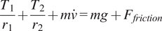
Three loading conditions are considered based on their function, as shown in Figure 7. In the first loading condition, the self-weight of the complete phantom, which is 2.809 kg force, is applied to its center of gravity. For the second and third conditions, a load of 0.4 kg force is applied in the direction of abduction and flexion motion, respectively. The force is applied at a distance of 0.266 m to generate a torque of 1,043.78 N-mm at the GH joint, equivalent to the maximum force required to lift the arm assembly about the GH joint having spring-loaded links. These loading conditions are applied for a range of dimensions by varying the link width and thickness, from which the suitable width of 0.03 m and thickness of 0.01 m are selected, which is compact enough to fit within the imaginary sphere of the GH assembly and is found to be safe from failure for all three conditions. In all three cases, no failure is exhibited in any part of the phantom for the selected dimensions. During the loading conditions shown in Figure 4(c) and (e), the maximum stress is on the carbon fiber pre-compression pin, which is below its maximum yield strength of 1,000 MPa, and the stress on the links is below the 55 MPa which is the maximum yield strength of PLA, making the phantom resistant to failure within its functional loading conditions having a factor of safety (FoS) of 2.5.
Static structural simulation results are the (a) and (b) Von Misses stress distribution and resultant deflection, respectively, for the self-weight loading condition; (c) and (d) Von Misses stress distribution and resultant deflection, respectively, for the abduction loading condition; and (e) and (f) Von Misses stress distribution and resultant deflection, respectively, for the flexion loading condition.
The maximum resultant deflection during abduction loading is 0.05 m, and flexion loading is 0.052 m, as shown in Figure 4(d) and (f), respectively; here, the deflection is greater because of the elastic nature of PLA. The resultant deflection is at the tip of the arm subassembly, resulting from the sum of all the link deformations. This deformation does not affect the strength and functionality of the device within its maximum loading conditions as per the simulation. As the stress falls within the allowable range for the selected GH assembly link dimensions, which must be limited to a 0.160 m diameter sphere for an FoS of 2.5, the deflection resulting from the static stress analysis is deemed safe.
3. Shoulder phantom prototype
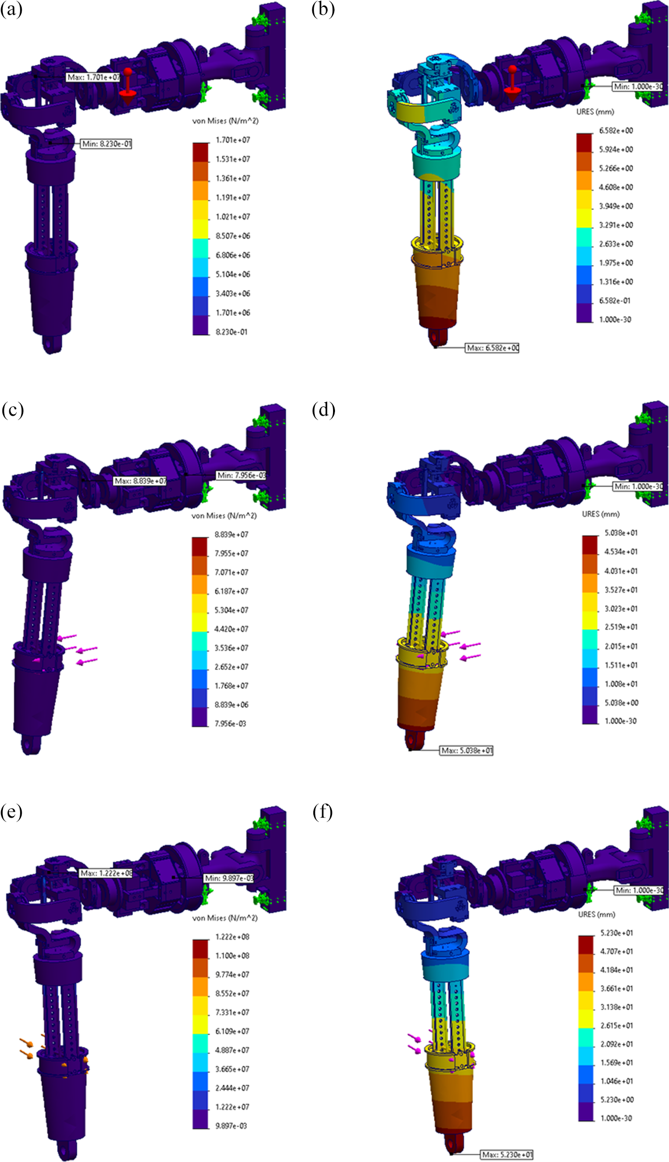
The shoulder phantom, depicted in Figure 8, is formed by coupling all subassemblies rapidly prototyped using fused deposition modeling with PLA. The phantom is mounted on the aluminum stand using the first link of the SG assembly and supported at the shoulder attachment from the bottom using a hollow carbon tube. The force sensor base is coupled to the SG assembly, and the force sensor slider is attached to the GH assembly. The curved springs used in the GH assembly are made of high-carbon steel inserted into the curved slots of the spherical links and pre-compressed from both ends using compression pins made of carbon rods. The joint angle sensors (rotary potentiometer), linear displacement sensors (linear potentiometer), limit switches, and linear actuator motors are connected to the Arduino MEGA 2560 microcontroller. Calibration and testing of the subassemblies and the whole system are presented in the following sections.
The fabricated shoulder phantom mechanism mounted on a fixed stand.
4. Linear actuator testing
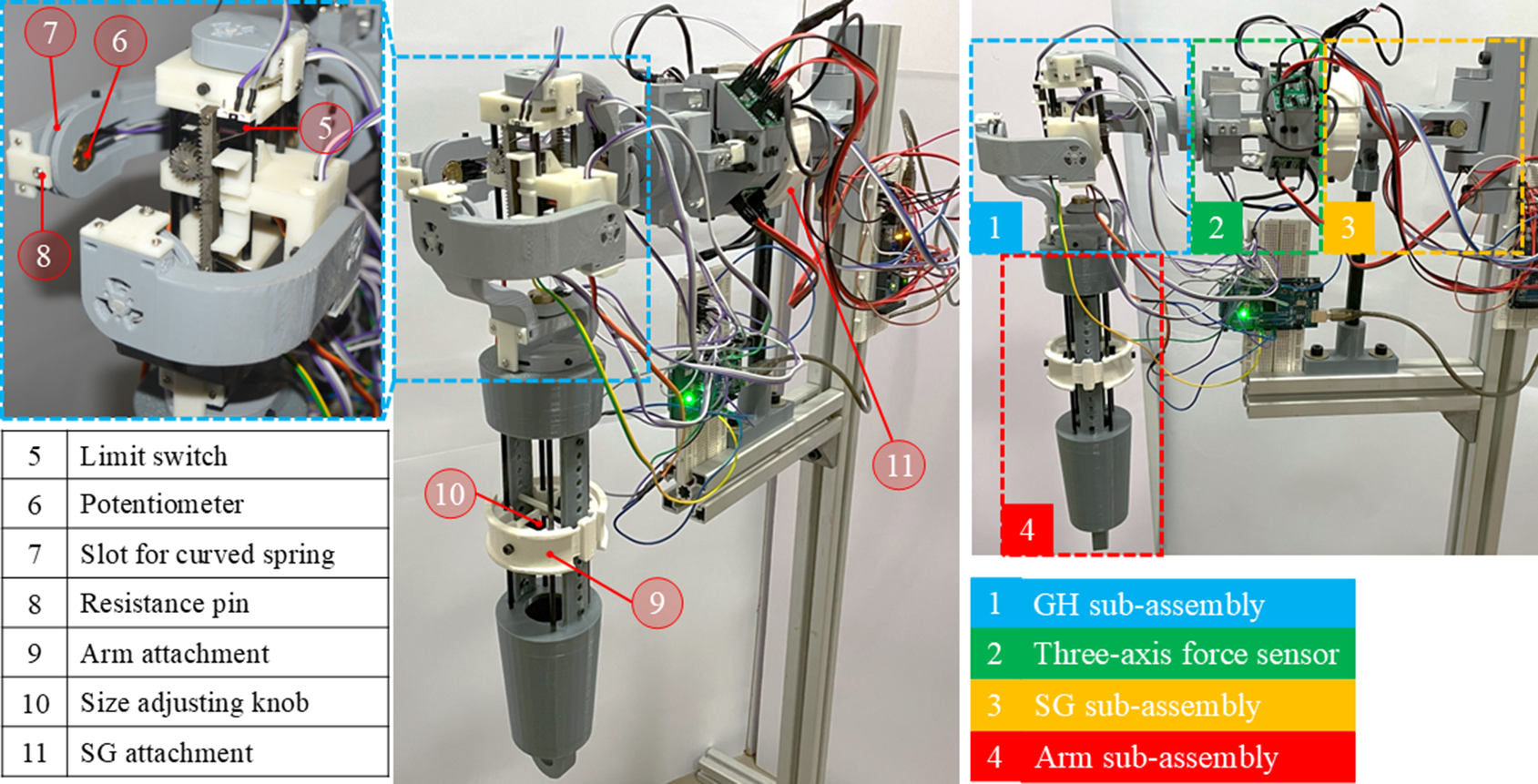
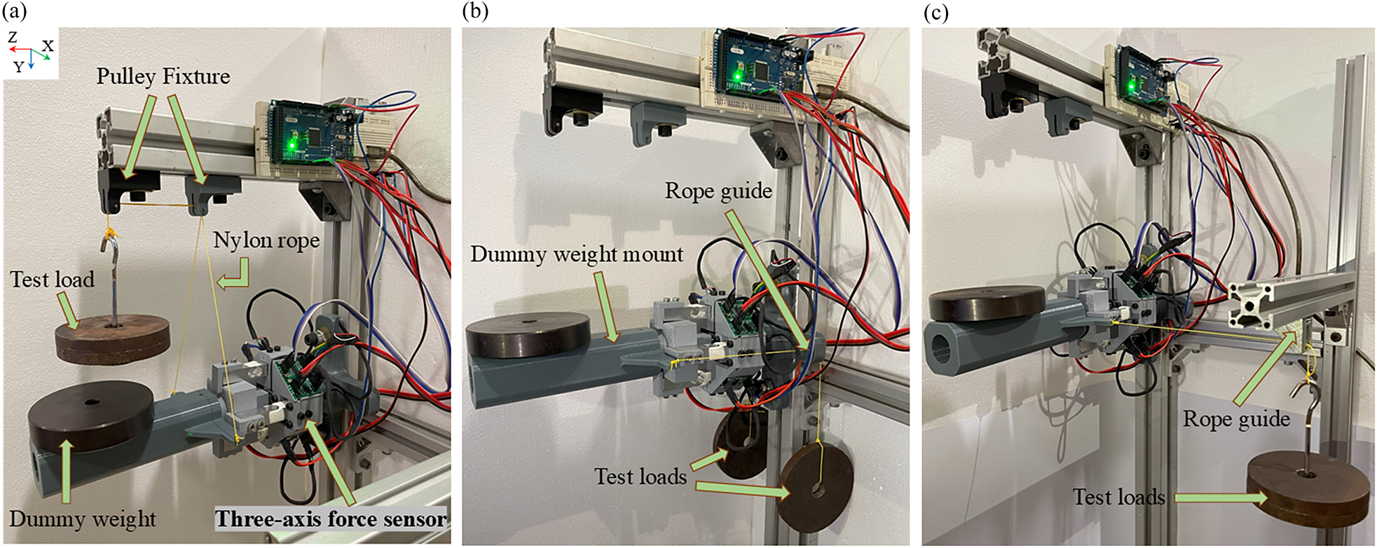
The linear actuator with rack and pinion transmission is tested and compared with a linear actuator of the same size with a cable and pulley transmission. Of the two designs, the rack and pinion transmission weighs 130.7 g, and the cable and pulley transmission weigh 86.7 g. In the cable-driven actuator, the cable whose two ends are attached to the static part of the actuator is wound around the two pulleys attached to the motors, which, when rotated in opposite directions, the platform translates. Therefore, theoretically, both show the same peak load-carrying capacity for a given torque without considering any losses due to gear friction or cable slippage on the pulley. To identify the better mechanism out of the two for providing linear actuation during the arm elevation without missing a step or slippage, both the actuation mechanisms are experimentally tested for a range of test loads with a setup, as shown in Figure 9(a) and (b).
(a) Rack and pinion transmission and (b) cable pulley transmission-based linear actuators mounted on a fixture, where the test load is suspended on the linearly actuating platform.
During the test, the actuator platform is made to translate upward and downward linear motion with the test weights attached to it. Then, the performance of the two actuators for no load and loading conditions is tested by gradually increasing the load. From Figure 10(a) and (b), it can be identified that the gear-driven actuator is capable of carrying a higher load with better efficiency compared to the cable-driven actuator, as in Appendix 1 of Supplementary Material 2.
The power (W) versus load (g) plot showing the comparison between the electrical input and the mechanical output for gear transmission-based linear actuator during downward and upward translations is shown in (a) and (b), respectively.
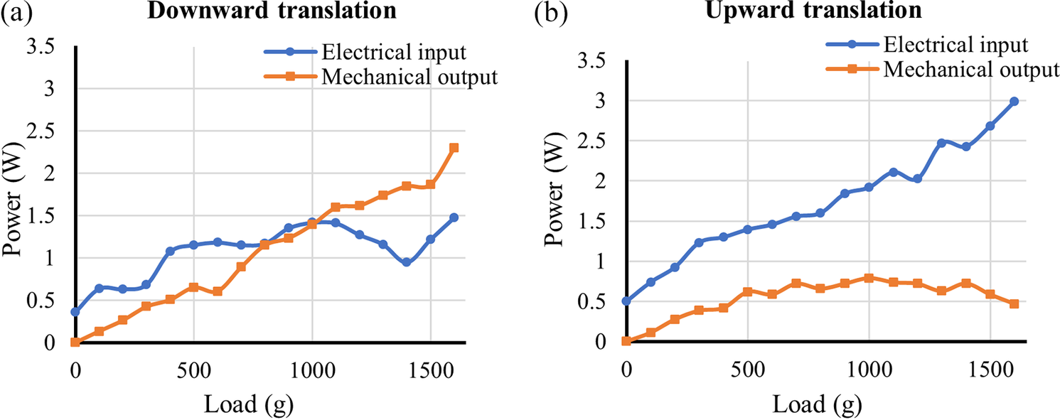
The experimentation shows that the cable-driven actuator consumed more power due to slippage along the upward and downward translations than the gear-driven actuator. Based on the observations and comparisons from the experiment, the gear-driven linear actuator is chosen for the application because of its better efficiency and load-carrying capacity.
5. Three-axis force sensor calibration
The force sensor module attached between the GH and SG joint subassembly measures the interaction forces generated between the phantom and the exoskeleton during arm elevation. A three-dimensionally printed three-axis force sensor module is used in this phantom to serve its purpose (Pramod et al., Reference Pramod, Adithya, Palani, Varala, Panigrahi, Mohan and Thondiyath2024c). For this application, the load cells attached to the force sensor must be calibrated in all five directions, and this cannot be carried out with the GH joint subassembly attached to it. So, the sensor is calibrated separately by attaching it to a fixed stand on one end, and the other end is mounted with a dummy weight mount, as shown in Figure 11. The sensor value is tared to zero once a dummy weight of 1.115 kg, which represents the combined weight of the arm and the GH subassembly, is placed on the mount. The calibration is carried out in all five directions by suspending a 1 kg test weight using a nylon rope attached to the dummy weight mount along the respective direction. The vertical upward load along the negative y-axis is applied using the setup shown in Figure 11(a). Similarly, the positive y-axis load is suspended freely attached to the mount. The calibration load setup in the negative z-axis and positive x-axis is shown in Figure 11(b) and (c), respectively; similarly, for loading along the negative x-axis, the same method is followed on the other side. Consequently, the calibration factor obtained for all the load cells is used to determine the interaction forces during the phantom arm elevation. The sensor’s sensing capability is limited from 1 to 10,000 g in all three directions. It has been noted that hysteresis and sensor drift are possible sources of error when the sensor is subjected to a higher load for an extended period. To reduce this error, the sensor values are tared to zero at the beginning of the experiment. During the experiment, the loading time and magnitude were insufficient to create hysteresis and sensor drift, which was validated based on the five datasets obtained during the experimentation.
Three-axis force sensor calibration setup with dummy weight on the mount. (a) The test load (1 kg) is suspended through the pulley attached to the fixture for calibration in the negative y-axis. (b) and (c) The test load is suspended through the rope guide for calibration in the negative z-axis and positive x-axis respectively.
To check the accuracy of the readings, test weights of 602.4, 1091.6, 2197.7, and 312.6 g were used. These weights are mounted by suspending them from the force sensor using nylon ropes following the abovementioned process utilized for calibration. Four readings are measured for each of the weights and each load cell, using which the average and standard deviation for the measured values of the weights are tabulated. An error bar plot is plotted from the tabulated values, as shown in Figure 12.
Error bar plots for individual load cells on the three-axis force sensor after calibration.
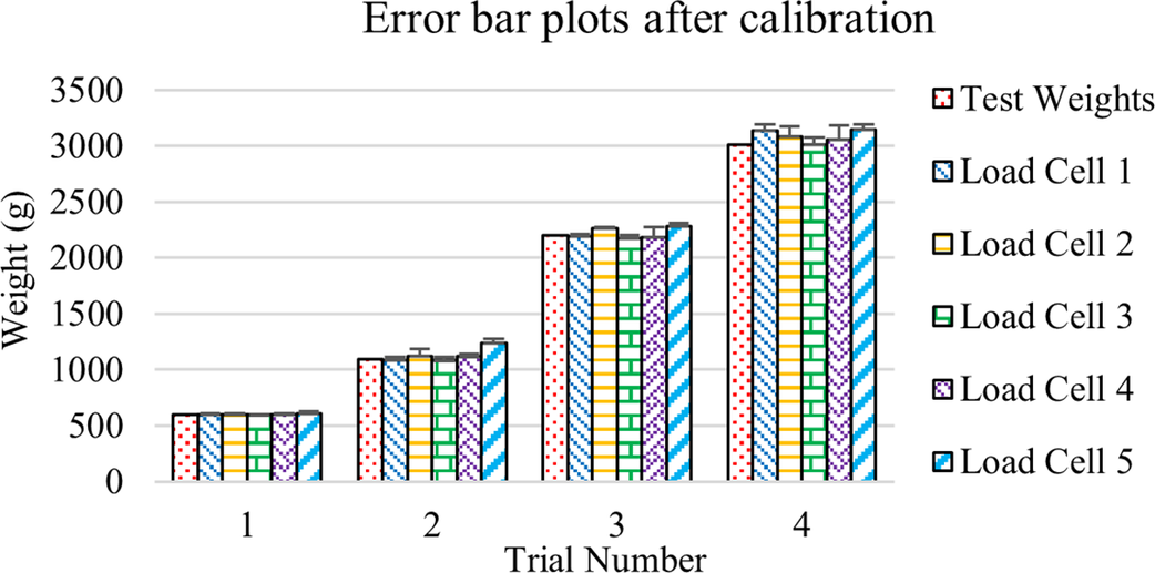
The plot shown in Figure 12 has a maximum standard deviation of 123.33 for the weight of 3,012.6 g on load cell 4. The minimum standard deviation is 0.608 for the weight of 602.4 g on load cell 3. The inaccuracy in measurements increases with an increase in weight, but is within the acceptable limits for the intended application.
6. Experimentation and results
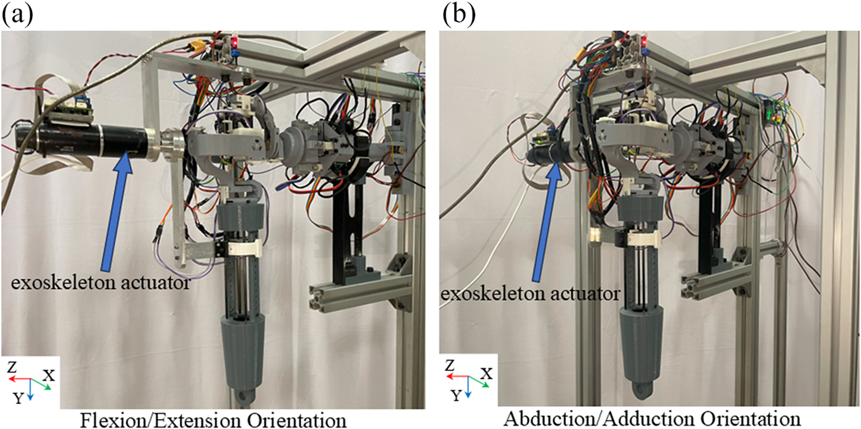
The experimentation is carried out on the shoulder phantom after its fabrication to test the interaction forces generated during arm elevation due to joint axis misalignment. Initially, the phantom arm elevation is carried out manually by an operator for abduction/adduction and flexion/extension, similar to a physiotherapist’s motion. These motions are repeated using a conventional exoskeleton attached to the phantom, as shown in Figure 13(a) and (b). The arm elevation is performed about the GH joint by keeping the SG motion arrested, and during elevation, the joint is moved to an angle of 130°. The flow chart for the conventional exoskeleton-assisted experimentation process is given in Figure 14. During phantom arm elevation, once the exoskeleton is actuated, the phantom arm starts moving along with the exoskeleton until the joint angle reaches 130° (abduction and flexion); similarly, during adduction and extension, the phantom arm moves with the exoskeleton till the joint angle reaches 0°. The force sensor provides the data throughout the phantom arm motion, and the interaction forces measured are mapped to the joint angle of the exoskeleton.
The conventional exoskeleton is attached in an orientation to perform (a) flexion/extension elevation of the phantom arm and (b) abduction/adduction elevation of the phantom arm.
Flow chart during conventional exoskeleton-assisted phantom arm elevation.
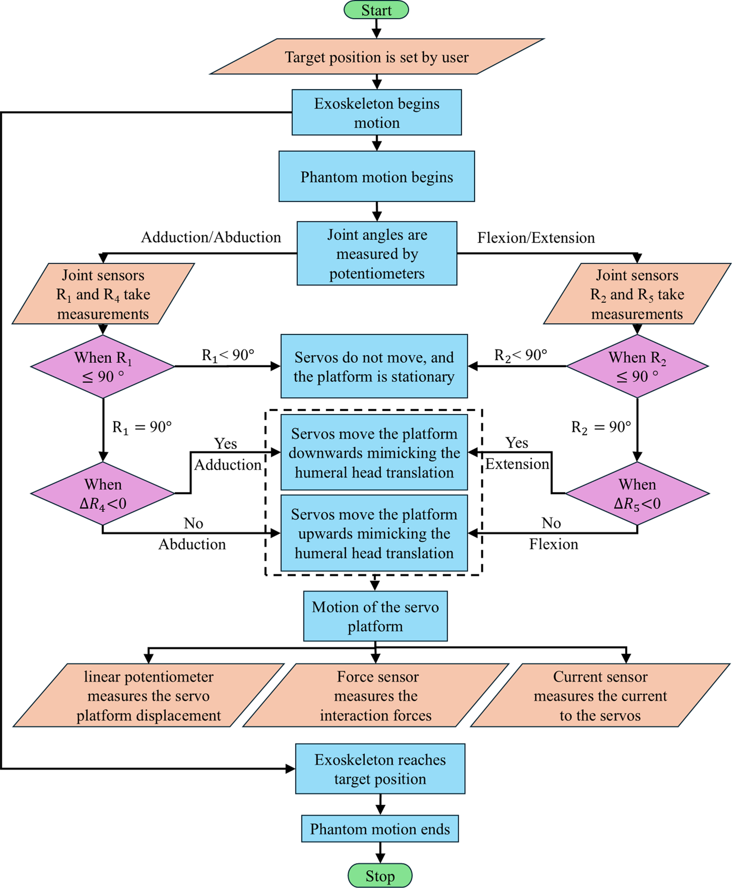
During the abduction motion, the joint $ {R}_1 $
moves to an angle of
$ {R}_1 $
moves to an angle of $ {90}^{{}^{\circ}} $
and stops, then the rest is completed by the joint
$ {90}^{{}^{\circ}} $
and stops, then the rest is completed by the joint $ {R}_4 $
. As soon as
$ {R}_4 $
. As soon as $ {R}_4 $
starts moving, the linear actuator translates
$ {R}_4 $
starts moving, the linear actuator translates $ {R}_4 $
up to a range of
$ {R}_4 $
up to a range of $ 15\;\mathrm{mm} $
from its center position toward the inferior direction, mimicking the humeral head translation and generating the joint axis misalignment between the joint
$ 15\;\mathrm{mm} $
from its center position toward the inferior direction, mimicking the humeral head translation and generating the joint axis misalignment between the joint $ {R}_4 $
and the exoskeleton or human arm, which induces the elevation. After the abduction, the phantom arm is rotated in the downward direction to perform the adduction motion, where the linear actuator translates
$ {R}_4 $
and the exoskeleton or human arm, which induces the elevation. After the abduction, the phantom arm is rotated in the downward direction to perform the adduction motion, where the linear actuator translates $ {R}_4 $
in the superior direction up to a range of 30
$ {R}_4 $
in the superior direction up to a range of 30 $ \mathrm{mm} $
from its extreme inferior position (video link in Appendix 3 of Supplementary Material 2). The interaction force is obtained for the joint rotation about the GH joint with respect to the joint between the GH joint assembly and the SG assembly using the three-axis force sensor. Based on the induced joint axis misalignments, the obtained interaction forces are compared for arm elevation assisted by the exoskeleton and the human arm.
$ \mathrm{mm} $
from its extreme inferior position (video link in Appendix 3 of Supplementary Material 2). The interaction force is obtained for the joint rotation about the GH joint with respect to the joint between the GH joint assembly and the SG assembly using the three-axis force sensor. Based on the induced joint axis misalignments, the obtained interaction forces are compared for arm elevation assisted by the exoskeleton and the human arm.
6.1. Conventional exoskeleton-assisted elevation
For the phantom shoulder, arm abduction/adduction, and flexion/extension using the conventional exoskeleton attachment, five sets of data are taken for two conditions with exoskeleton joint rotation of 3.968 RPM, one with induced humeral head translation in the phantom shoulder and the other without translation. The actuator speed is taken as 3.968 RPM, such that the arm elevation has an average angular velocity of 23 degrees per second, the average slow speed for rehabilitation (Ito et al., Reference Ito, Fukuda, Hosoi, Hirose, Teramae, Kamimoto, Yamada, Tsuji, Noda and Kawakami2024). The average from the five datasets is plotted to obtain the forces acting in all five directions: the positive and negative x, y-axis, and the negative z-axis. Figure 15 shows the force versus joint angle plot for abduction and adduction in the yz-plane and flexion and extension in the xy-plane, where the blue curve represents the dataset without translation, and the orange curve represents the dataset with translation.
The interaction forces in the positive and negative y-axis measured while the conventional exoskeleton performs abduction and adduction (Ab/Ad) with the phantom are in (a) and (b), respectively, and for the flexion and extension (Fl/Ex) are in (c) and (d), respectively. The interaction forces are measured for the two cases, one with translation of the second spherical joint and the other without translation. The interaction forces in the positive x-axis, negative x-axis, and negative z-axis for both Ab/Ad and Fl/Ex are given in Appendix 2 of Supplementary Material 2.
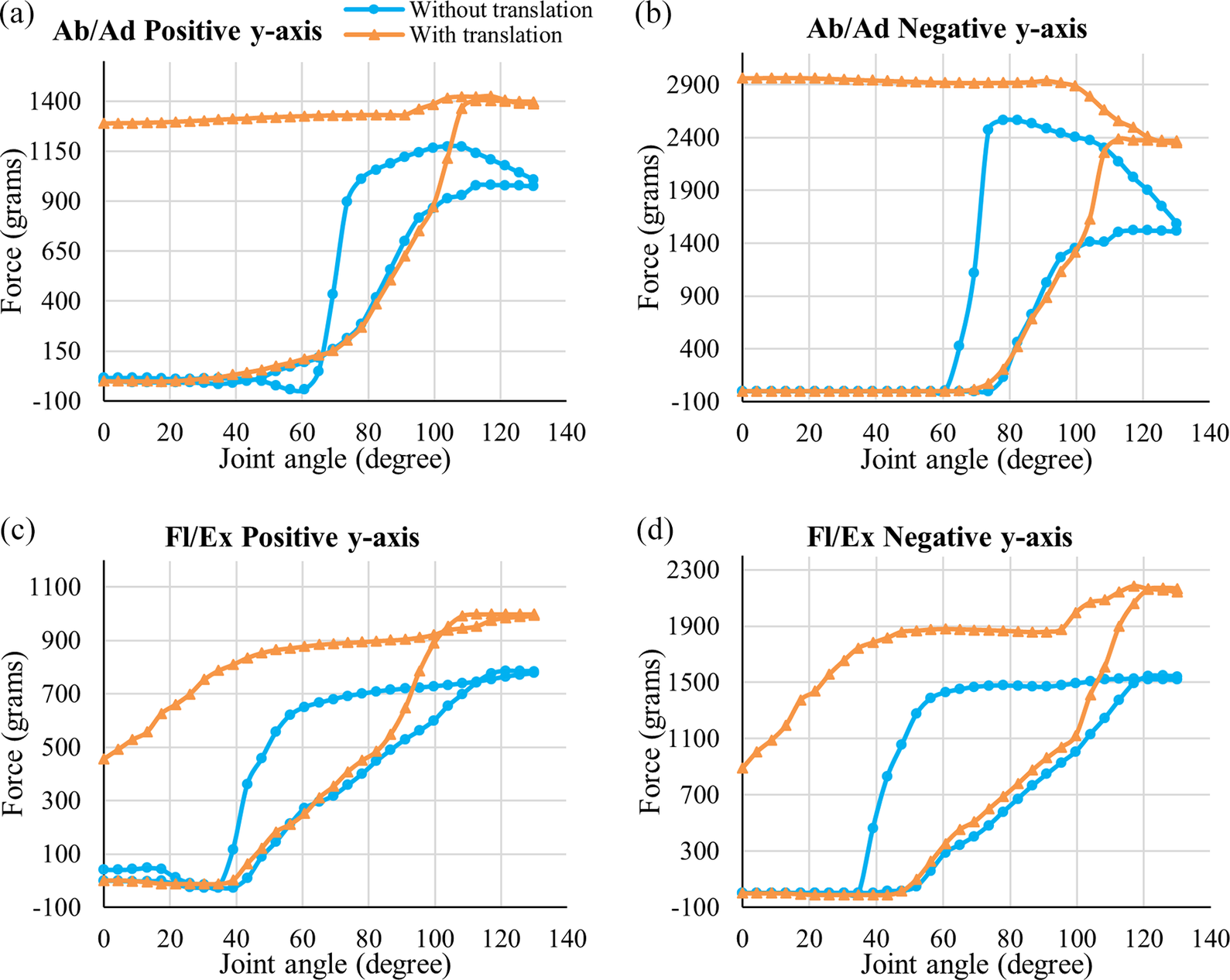
It can be observed from the obtained data that during both motions without translation, there is an increase in forces acting at the joint during elevation, and it drops to its initial value when the arm is brought back to its original position. This initial increase in force is due to minor joint axis misalignment between the shoulder joint and the exoskeleton actuator axis of rotation, even though both the joint axes were perfectly aligned when viewed with the naked eye. This force variation during elevation without translation is a result of all the spring forces, minor misalignment, and joint friction.
During the arm elevation with translation, the interaction forces between the conventional exoskeleton and the shoulder phantom in all five directions vary from the forces generated when the arm elevation is carried out without the misalignment. The force values spike to a higher or lower value based on the direction when the misalignment is induced by translating the second spherical joint to its extreme inferior position. Similarly, when the arm is rotated in the downward direction, a superior translation of the spherical joint is induced to its extreme position; this causes the interaction force to remain high or low and not come to its initial value. These higher interaction forces obtained during the experimentation show that the humeral head translation is an important aspect of human shoulder motion and must be considered while designing the upper limb exoskeleton mechanisms.
6.2. Human-assisted elevation
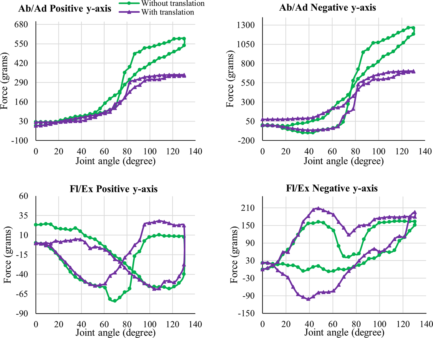
A similar phantom arm elevation is performed for abduction/adduction and flexion/extension with human assistance, as performed by physiotherapists. It is done to understand the interaction forces generated between the shoulder phantom and the human. Both abduction/adduction and flexion/extension elevations are performed with translation and without translation of the second spherical joint from its initial position. This experiment was carried out for five datasets while maintaining a rotational velocity similar to that of the exoskeleton in the previous experiment. Figure 16 shows the force versus joint angle plot, where the green curve represents the dataset without translation, and the purple curve represents the dataset with translation. It can be observed from the data that the interaction forces are almost similar in both cases. The measured forces at the beginning and end of the cycle are similar, and the shift in force values and the minor variations are due to the irregularity in the angular velocity at certain points because of the manual hand motion to lift the phantom arm. This result is compared with the experimental results of the phantom arm elevation using the conventional exoskeleton, and a detailed discussion is provided in the following section.
The interaction forces in the positive and negative y-axis measured while the human assists in performing abduction and adduction with the phantom are in (a) and (b), respectively, and for the flexion and extension are in (c) and (d), respectively. The interaction forces are measured for the two cases, one with translation of the second spherical joint and the other without translation. The interaction forces in the positive x-axis, negative x-axis, and negative z-axis for both Ab/Ad and Fl/Ex are given in Appendix 2 of Supplementary Material 2.
7. Discussion
The interaction forces during the phantom arm elevation assisted by the conventional exoskeleton and the human arm have visible differences in all five directions measured using the three-axis force sensor. A comparison is made for the interaction forces during conventional exoskeleton-assisted and human-assisted motion in the positive y-axis, as shown in Figure 17.
The interaction forces in the positive y-axis measured while the conventional exoskeleton-assisted and human-assisted motions performed (a) abduction and adduction, and (b) flexion and extension.
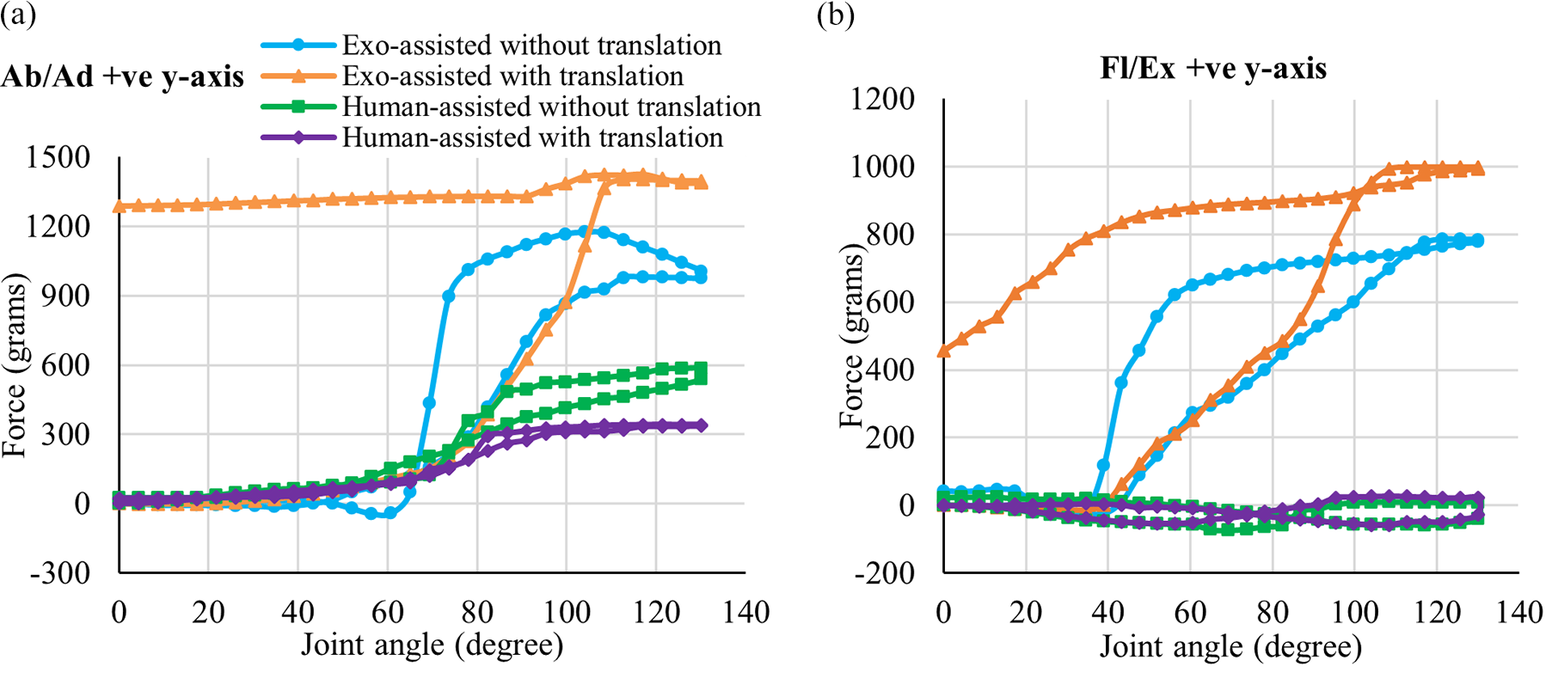
The interaction force and its variation are more predominant in the positive and negative y-axis during both flexion/extension and abduction/adduction using the exoskeleton because of the resultant force due to the misalignment, joint resistance, and the applied force required to lift the phantom arm. In positive and negative x-axis directions, the interaction forces during abduction/adduction have less variation than the flexion/extension because of the translation in xy-plane. The conventional exoskeleton has a more significant interaction force due to joint misalignment when the humeral head translation is induced, which shows how the shoulder joint components of the wearer are affected. Some of the critical observations from the results are as follows:
-
• When exoskeletons that do not consider the humeral head translation in their design are used for physiotherapy on stroke patients with partial paralysis/joint injuries, they can damage the shoulder joint components during the large interaction forces generated from axes misalignment. This is one of the reasons for the low effectiveness of the exoskeletons in physiotherapy compared to human-assisted therapy.
-
• The wearable exoskeletons used in assistance and augmentation will have a reduced ROM due to the joint axis misalignment, leading to further injury to the user. The interaction forces during the phantom arm elevation using the human arm are less because the human arm has redundant compliant joints, which facilitate the free translation of the humeral head in the phantom.
-
• The design of wearable exoskeletons should be based on a more human-centric shoulder model so that they have similar flexibility as the human upper limb.
-
• Direct testing of the exoskeleton on human volunteers should be avoided during the initial research and development stage to avoid any possible injuries.
This research introduces an innovative approach to designing and testing human-centric wearable upper limb exoskeletons using a test bench that simulates upper limb joint motion, eliminating the need for direct human testing. It further focuses on overcoming the challenges in designing the exoskeleton (Bengler et al., Reference Bengler, Harbauer and Fleischer2023), for it to be more human-centric by introducing joint-to-joint misalignment tracking, which can help the exoskeleton achieve its full potential when paired with a human body.
The prototype presented can be further modified to have active, actuated revolute joints to improve its capability to mimic the human shoulder. The three-axis sensor used in this prototype can be replaced with a compact industrial-grade force sensor for better performance. For the active prismatic joint, the servomotors actuating the mechanism can be replaced with two high-precision servomotors, providing better precision during actuation.
8. Conclusion
An upper limb exoskeleton test bench has been developed with an anatomical joint configuration similar to that of a human shoulder. This shoulder phantom provides easy attachment and testing of the upper limb exoskeletons for their maximum reachability and self-aligning capability. The self-aligning capability is understood based on the interaction forces measured due to misalignment between the exoskeleton and shoulder phantom joint axis using a three-axis force sensor attached between the GH and SG subassembly. The phantom has a rack and pinion-based servo-actuated linear actuator that mimics the humeral head translation from the glenoid fossa of the scapula. Using a conventional exoskeleton, the developed phantom is tested by performing abduction/adduction and flexion/extension. Similarly, to compare the results, a human-assisted phantom arm elevation is also performed. The results show increased interaction forces between the conventional exoskeleton and the phantom when joint axis misalignment is induced between them. This proves that the conventional exoskeletons are not designed to account for the humeral head translation, which can further reduce the exoskeleton’s usability and ROM. Thus, the exoskeletons under the research and development process must be tested on shoulder phantoms before testing directly on the human volunteers. This phantom can be further integrated with an on-screen display setup to show real-time interaction with the exoskeleton and to understand its performance, based on which the design of the exoskeleton can be improved.
The proposed shoulder phantom can be modified to be used as a benchmark test setup that can experimentally compare and validate the upper limb wearable exoskeletons in the market. The same mechanism can be incorporated in humanoid robot shoulders for maximum ROM, having all active joints actuated using an actuator. For this prototype, one of the issues in making it active is to make the joints and links compact with actuators incorporated at the joints. This needs to be addressed by changing the material used for the links and choosing compact actuators having the required weight-to-power ratio. Different exoskeleton configurations can be tested and compared on the phantom because of its capability to have a variable size- and length-adjustable attachment on the SG and arm subassembly. Similarly, when the exoskeleton is mounted at various arm positions, the experiment can be conducted to assess the variance in interaction force. Using the phantom’s capability to have a variable attachment size and length can also help perform user-specific testing to analyze the phantom’s adaptability and generalizability. However, the testing and comparison of various existing exoskeleton configurations present in the literature, based on their capability to reduce interaction forces due to misalignment, to assess the maximum reachable ROM and the complex dynamic interactions at a wider range of phantom arm trajectory is kept as the future scope of this work. The phantom can further be used to develop a modified wearable shoulder exoskeleton mechanism capable of reducing the interaction forces with the human shoulder (Pramod et al., Reference Pramod, Mohan and Thondiyath2024d; Pramod et al., Reference Pramod, Thondiyath and Mohan2024e). The exoskeleton can then be compared with the existing conventional exoskeletons and further improved before going for human trials.
Supplementary material
The supplementary material for this article can be found at http://doi.org/10.1017/wtc.2025.10006.
Data availability statement
Data availability is not applicable to this article as no new data were created or analyzed in this study.
Acknowledgments
The authors would like to thank the Indian Institute of Technology, Madras, and the Indian Institute of Technology Palakkad Technology IHub Foundation (IPTIF) for providing the lab and resources to conduct the research.
Authorship contribution
Avinash S. Pramod conceptualized the work, did a literature survey, made the design, did the simulation, did system integration and developed the prototype, performed tests on the prototype, carried out experimentations, processed and interpreted the data, prepared the first draft, and made the final manuscript. Adithya R.N. assisted in CAD modeling, assisted in system integration, assisted in testing of the prototype, assisted in experimentations, and reviewed the final manuscript. Santhakumar Mohan and Asokan Thondiyath provided inputs for conceptualization, reviewed the draft, provided critical reviews, and corrected the manuscript. All authors approved the final submitted draft.
Funding statement
This research received no specific grant from any funding agency, commercial, or not-for-profit sectors.
Competing interests
The authors declare no competing interests exist.
Ethical standard
Not applicable.


 Open access