





Impact Statement
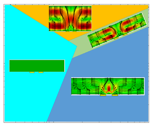
The article presents the first comprehensive investigation of Joule heating-induced fluid motion in microchannels around a pair of electrodes in a high conductive buffer under alternating current electric fields. This transport mechanism is widely used for biomedical applications due to the high conductivity of biological buffers. Buoyancy-driven and alternating current electrothermal (ACET) flows are the main transport mechanisms that induce two counter-directions of vortical flow around the electrodes. This study reveals a competition between these two flows, and this competing effect is characterized by a new non-dimensional parameter. This new parameter was used to construct a phase diagram that enabled the prediction of the ACET and buoyancy-driven flow dominancy as a function of the applied electric field and channel size. This phase diagram was verified using numerical simulation and experimental techniques. Overall this paper paves the way for a systematic design process for Joule heating based microfluidics devices.
1. Introduction
Electrokinetic transport requires the application of electric fields onto ionized fluids and their interaction with polarizable or charged particles and surfaces. This results in various phenomena, including electro-osmosis, electrophoresis and dielectrophoresis (Reference Karniadakis, Beskok and AluruKarniadakis, Beskok, & Aluru, 2005). Imposing locally applied electric fields in miniaturized channels allows precisely controlled flow and charged species transport in microfluidic systems (Reference Dutta, Beskok and WarburtonDutta, Beskok, & Warburton, 2002). Especially utilizing alternating current (AC) electric fields at high frequencies (typically above 1 kHz) reduces the detrimental effects of Faradaic reactions while maintaining the desired function of these systems (Reference Song, Lin, Peng, Zhang and WuSong, Lin, Peng, Zhang, & Wu, 2022).
Here, we focus on using AC electric fields to create local fluid flow for mixing, pumping and other lab-on-a-chip (LOC) type applications. For example, AC electro-osmosis (ACEO) flow happens due to the electrical body force induced on the ionic charges within the electric double layer (EDL) at the fluid/electrode interface. This body force is due to the tangential component of the electric field near the electrodes, which is dominant for thick EDL conditions observed in low ionic conductivity (σ) buffers (typically for σ ≤ 0.2 S m−1) (Reference Salari, Navi and DaltonSalari, Navi, & Dalton, 2015). The EDL thickness reduces with increased ionic concentration, and the effectiveness of ACEO rapidly weakens due to the diminishing tangential electric field on the electrode (Reference Karniadakis, Beskok and AluruKarniadakis et al., 2005). The ACEO flow has been used in many LOC devices for pumping (Reference Yoshida, Sato, Eom, Kim and YokotaYoshida, Sato, Eom, Kim, & Yokota, 2017) and mixing (Reference Modarres and TabrizianModarres & Tabrizian, 2020) in low-conductivity fluids.
Electric currents passing through the ionic fluids result in Joule heating, which increases with the increased electric field and ionic conductivity of the medium. Joule heating in most ACEO flows is limited due to the low ionic conductivity unless the applied electric fields are significant. On the other hand, most biological microfluidic applications utilize physiological buffers with large conductivities (σ ≈ 1.5 S m−1), where the Joule heating cannot be ignored. An interesting transport phenomenon due to Joule heating is the electrothermal flow that happens due to the temperature dependence of the buffer permittivity and conductivity. The AC electrothermal (ACET) flows over planar interdigitated electrodes create vortical flow structures comparable to that observed in ACEO flows (Reference Hossan, Dutta, Islam and DuttaHossan, Dutta, Islam, & Dutta, 2018; Reference Wang, Sigurdson and MeinhartWang, Sigurdson, & Meinhart, 2005). Due to this similarity, ACET flows have been investigated for pumping and mixing in drug delivery and discovery applications (Reference Lang, Ren, Hobson, Tao, Hou, Jia and JiangLang et al., 2016), immunoassay systems (Reference Feldman, Sigurdson and MeinhartFeldman, Sigurdson, & Meinhart, 2007; Reference Koklu, Giuliani, Monton and BeskokKoklu, Giuliani, Monton, & Beskok, 2020; Reference Sigurdson, Wang and MeinhartSigurdson, Wang, & Meinhart, 2005) and cell cultures (Reference Lang, Wu, Ren, Tao, Lei and JiangLang et al., 2015; Reference Luni, Feldman, Pozzobon, De Coppi, Meinhart and ElvassoreLuni et al., 2010) in high-conductivity media. It is essential to indicate that non-uniform heating of the fluid due to Joule heating also results in buoyancy-driven flows (BDFs), where the low density hot fluid rises, and the high density cold fluid falls under the gravitational body force. Since the BDF co-occurs with electrothermal flow (ETF), the importance of these two phenomena needs to be characterized for their proper use in microfluidic applications. Most previous theoretical and numerical investigations in the literature considered ACET flow without the BDF (Reference Hong, Bai and ChengHong, Bai, & Cheng, 2012; Reference Yuan, Yang and WuYuan, Yang, & Wu, 2014). However, these two effects may enhance or impede each other while inducing unique local flow patterns in microfluidic systems.
Reference Loire, Kauffmann, Mezić and MeinhartLoire, Kauffmann, Mezić, and Meinhart (2012) investigated the importance of ETF and BDF numerically and experimentally. Their numerical model solved the coupled electric field, fluid flow and heat transfer equations with temperature-dependent fluid properties. They numerically compared the velocity fields around a pair of electrodes obtained with or without the buoyancy effects. The numerical simulation results were also compared with the velocity measurements using the micro-particle-image-velocimetry (μ-PIV) technique. Numerical results matched the experiments when the buoyancy effects were considered. In a following study, Reference WilliamsWilliams (2013) used the numerical model developed by Reference Loire, Kauffmann, Mezić and MeinhartLoire et al. (2012), demonstrating that BDF induced by a thin film heater could considerably increase the flow rate in an ETF pump, proving the importance of BDF in such microfluidic systems.
Reference Lu, Ren, Liu, Leung, Gau, Liao and WongLu et al. (2016) conducted a series of μ-PIV experiments of ACET flow occurring between two parallel electrodes in microchannel heights varying from 800 to 300 μm, and measured the velocity fields at the electrode gap region and downstream/upstream regions of the microelectrode. They observed two small vortices in the electrode gap region due to the ACET flow, while two large vortices in reversed directions were identified in the upstream/downstream regions due to the BDF. Reference Lu, Ren, Liu, Leung, Gau, Liao and WongLu et al. (2016) also presented numerical simulation results that modelled both ACET and BDF with spatially varying material properties as a function of temperature. Although they reported the co-occurrence of these two types of flows, they did not present a systematic investigation as a function of channel dimensions and operation conditions.
Reference Koklu, El Helou, Raad and BeskokKoklu, El Helou, Raad, and Beskok (2019) investigated the temperature rise in a high-conductivity medium due to Joule heating in a microchannel system using the thermal reflectance imaging technique. Systematic surface temperature measurements were conducted under AC electric fields varying from 1 Vpp to 20 Vpp. The reported temperature rises matched the predictions of numerical simulations that considered both ACET and BDFs. Having studied the surface temperature variations due to Joule heating before, here, we focus on the flows induced by Joule heating. The objective of this manuscript is to delineate and distinguish the relative importance of the buoyancy-driven and ACET flows that simultaneously occur due to Joule heating in high-conductivity buffers. Here, we specifically consider high-conductivity buffers (σ > 0.2 S m−1), so that ACEO flow is limited.
This study is organized as follows. We first present proper non-dimensionalization of the energy and momentum equations and then identify the ratio of the electrothermal and buoyancy-driven flow velocities as a new non-dimensional parameter to determine the dominant regions of each flow within a phase diagram. Using the flow generated by a symmetric pair of planar electrodes in a microchannel as a characteristic system, we present numerical results of mixed ACET and BDFs for varying channel dimensions, applied electric fields and ionic conductivities, and verify the phase diagram. This is followed by the μ-PIV measurements of the resulting flow to validate the numerical results. We finally summarize our findings and conclude.
2. Methods
2.1 Theory
Electrokinetic transport refers to the fluid and particle motion due to an externally applied electric field. The AC ETF arises from the non-uniform permittivity and conductivity of the fluid due to the temperature gradient in the domain, typically induced by Joule heating. Numerical modelling of this flow requires a solution for the electric field equations coupled with the fluid flow and energy equations. The electric field is determined by Gauss’ law, charge conservation and Faraday's law, given as follows:
 \begin{gather}\boldsymbol{\nabla }\boldsymbol{\cdot }(\varepsilon \boldsymbol{\nabla }\varphi ) = {\rho _e},\end{gather}
 \begin{gather}\frac{{\partial {\rho _e}}}{{\partial t}} + \boldsymbol{\nabla }\boldsymbol{\cdot }(\sigma \boldsymbol{\nabla }\varphi ) = 0,\end{gather}
 \begin{gather}\boldsymbol{\nabla } \times \boldsymbol{\nabla }\varphi = 0,\end{gather}
where ɛ (F m−1) is the electrical permittivity, ρe (C m−3) is the space charge density, σ (S m−1) is the electrical conductivity, t (s) is time and  $\varphi (\textrm{V})$ is the electric potential. Considering small variations in permittivity and conductivity with temperature, and AC fields with frequencies less than $\sigma /2\mathrm{\pi }\varepsilon $ (Reference Kale, Patel, Hu and XuanKale, Patel, Hu, & Xuan, 2013; Reference Sridharan, Zhu, Hu and XuanSridharan, Zhu, Hu, & Xuan, 2011), the quasi-static electric potential (φ) can be calculated by
 \begin{equation}{\nabla ^2}\varphi = 0.\end{equation}
The resultant electric field E (V m−1) is defined as the gradient of the electric potential  $(\boldsymbol{E} ={-} \boldsymbol{\nabla }\varphi )$. In order to solve this equation, ${\pm} \varphi (\textrm{V})$ is applied on the electrodes, while a zero charge condition is applied on the rest of the boundaries.
The electric field applied in high-conductivity medium generates Joule heating that induces temperature gradients in the microchannel. Therefore, the energy equation is solved with the Joule heating source term
 \begin{gather}{\rho _m}{C_p}\left( {\frac{{\partial T}}{{\partial t}} + (\boldsymbol{u}\boldsymbol{\cdot }\boldsymbol{\nabla })T} \right) = \boldsymbol{\nabla }\boldsymbol{\cdot }({k_m}\boldsymbol{\nabla }T) + S,\end{gather}
 \begin{gather}S = \sigma (\boldsymbol{E}\boldsymbol{\cdot }\boldsymbol{E}),\end{gather}
where ρm (kg m−3) is the fluid density, Cp (J K−1) is the heat capacitance, T (K) is temperature, u (m s−1) is velocity,  ${k_m}(\textrm{W}\;{\textrm{(m} \cdot \textrm{K)}^{ - \textrm{1}}})$ is the fluid heat conductivity and S (J m−3) is the Joule heating source term.
After applying the electric field, the temperature field rapidly reaches a stationary state with both time-independent and oscillating components. The effect of the oscillating component on fluid dynamics is negligible for AC electric field frequencies higher than 1 kHz (Reference Castellanos, Ramos, Gonzalez, Green and MorganCastellanos, Ramos, Gonzalez, Green, & Morgan, 2003). For microfluidic devices, the convective term in (2.5) is insignificant, and the time to reach a steady state for heat transfer ( $t = {\rho _0}{C_p}L_c^2/{k_m}$, where Lc is the characteristic length) is often smaller than 0.1 s. Based on these simplifications, the energy equation reduces to the following form with a time-averaged source term:
 \begin{gather}\boldsymbol{\nabla }\boldsymbol{\cdot }({k_m}\boldsymbol{\nabla }T) + \langle S\rangle = 0,\end{gather}
 \begin{gather}\langle S\rangle = {\textstyle{1 \over 2}}\sigma (\boldsymbol{E}\boldsymbol{\cdot }\boldsymbol{E}),\end{gather}
where the  $1/2$ coefficient in front of (2.8) comes from assuming a sinusoidal signal with ${\pm} \varphi(\textrm{V})$ applied on the electrodes.
Since the channel is surrounded by a solid glass domain, heat generated in the fluid transfers through the walls to the environment. The temperature distribution in the solid section is determined from the steady-state heat conduction equation as follows:
 \begin{equation}\boldsymbol{\nabla }\boldsymbol{\cdot }({k_s}\boldsymbol{\nabla }T) = 0,\end{equation}
where the  ${k_s}\;(\textrm{W}\;{(\textrm{m} \cdot \textrm{K})^{ - 1}})$ is the solid's heat conductivity. Heat transfer across the fluid–solid interface is determined by considering the temperature gradients with heat transfer coefficients at the interface using a conjugate heat transfer model. Simulation software uses the material properties of both the solid and fluid domains to solve the equations and determine heat transfer across the interface. Since most of the microfluidic devices work at room temperature, a constant temperature (293.15 K) boundary condition was assumed around the solid domain exposed to the surrounding air.
The electric field and temperature gradient in the domain induce electrical and buoyancy forces on the fluid. The resulting flow is determined by the solution of the Navier–Stokes equation
 \begin{equation}{\rho _m}\left( {\frac{{\partial \boldsymbol{u}}}{{\partial t}} + (\boldsymbol{u}\boldsymbol{\cdot }\boldsymbol{\nabla })\boldsymbol{u}} \right) = {-} \boldsymbol{\nabla }p + \boldsymbol{\nabla }\boldsymbol{\cdot }(\mu (\boldsymbol{\nabla }\boldsymbol{u} + {(\boldsymbol{\nabla }\boldsymbol{u})^T}) + {\boldsymbol{F}_{\boldsymbol{e}}} + {\boldsymbol{F}_{\boldsymbol{b}}},\end{equation}
where μ (Pa⋅s) is the fluid viscosity, p (Pa) is the pressure, Fe is the electrical force and Fb is the buoyancy force. It is essential to indicate that the fluid density  $({\rho _m})$, viscosity $(\mu )$ and thermal conductivity $({k_m})$ are functions of the local temperature, while incompressible flow requires a divergence-free velocity field to satisfy the mass conservation.
Microfluidic devices have small characteristic dimensions with low fluid velocities, which often result in the Stokes flow limit, where the Reynolds number,  $Re \ll 1$. The diffusion time scale $(t = {\rho _m}L_c^2/\mu )$ dominates over the convective effects, and fluid flows in these systems reach a steady state usually in less than 0.01 s. Under such simplifications, the steady-state momentum equation becomes
 \begin{equation}{-}\boldsymbol{\nabla }P + \boldsymbol{\nabla }\boldsymbol{\cdot }(\mu (\boldsymbol{\nabla }\boldsymbol{u} + {(\boldsymbol{\nabla }\boldsymbol{u})^T}) + {\boldsymbol{F}_{\boldsymbol{e}}} + {\boldsymbol{F}_{\boldsymbol{b}}} = {\bf 0}.\end{equation}
In this equation, Fe and Fb are given by
 \begin{gather}{\boldsymbol{F}_{\boldsymbol{e}}} = \frac{1}{2} \frac{{\varepsilon ({{c_\varepsilon } - {c_\sigma }} )}}{{1 + {{\left( {\frac{{2\mathrm{\pi }f\varepsilon }}{\sigma }} \right)}^2}}}(\boldsymbol{\nabla }T\boldsymbol{\cdot }\boldsymbol{E})\boldsymbol{E} - \frac{1}{4} \varepsilon {c_\varepsilon }\boldsymbol{\nabla }T(\boldsymbol{E}\boldsymbol{\cdot }\boldsymbol{E}),\end{gather}
 \begin{gather}{\boldsymbol{F}_{\boldsymbol{b}}} = {\rho _m}\boldsymbol{g},\end{gather}
where g (m s−2) is the gravitational acceleration and f is the AC electric field frequency. The parameters  ${c_\varepsilon }$ and ${c_\sigma }$ are obtained from the Taylor series expansion of σ (T) and ɛ (T). For water, ${c_\varepsilon } = (1/\varepsilon )(\partial \varepsilon /\partial T)\sim{-} 0.004\;{\textrm{K}^{ - 1}}$, ${c_\sigma } = (1/\sigma )(\partial \sigma /\partial T)\sim 0.02\;{\textrm{K}^{ - 1}}$ at a reference temperature of 298.15 K (Reference LideLide, 2004).
The Boussinesq approximation is assumed to model the buoyancy force due to the non-isothermal flow. In microfluidic devices, changes in density due to pressure variations are negligible because of the microscale dimensions (there is no significant change in hydrostatic pressure) (Reference BejanBejan, 2022). Therefore, the density variation is mainly a function of temperature (Reference Cengel, Klein and BeckmanCengel, Klein, & Beckman, 1998). Using Taylor series expansion, the fluid density can be written as
 \begin{equation}{\rho _m} \cong {\rho _0} + {\left( {\frac{{\partial \rho }}{{\partial T}}} \right)_p}(T - {T_0}),\end{equation}
where  ${T_0}$ is the reference temperature (298.15 K) and ${\rho _0} = {\rho _m}({T_0})$. Using the volume expansion coefficient $\beta ={-} (1/{\rho _0}){(\partial \rho /\partial T)_p}$ (Reference BejanBejan, 2013), this equation is simplified to
 \begin{equation}{\rho _m} \cong {\rho _0} - {\rho _0}\beta (T - {T_0}).\end{equation}
Substitution of this buoyancy force into the steady Stokes equation gives
 \begin{equation}{-}\boldsymbol{\nabla }p + \boldsymbol{\nabla }\boldsymbol{\cdot }(\mu (\boldsymbol{\nabla }\boldsymbol{u} + {(\boldsymbol{\nabla }\boldsymbol{u})^T}) + {\boldsymbol{F}_{\boldsymbol{e}}} + {\rho _0}\boldsymbol{g} - {\rho _0}\beta (T - {T_0})\boldsymbol{g} = {\bf 0}.\end{equation}
In general, the  ${\rho _0}\boldsymbol{g}$ term creates hydrostatic pressure in the system, which can be included in the pressure gradient term. However, the hydrostatic pressure variations in microchannels are negligible due to their minuscule height, so the above equation can be further simplified to
 \begin{equation}{-}\boldsymbol{\nabla }(p) + \boldsymbol{\nabla }\boldsymbol{\cdot }(\mu (\boldsymbol{\nabla }\boldsymbol{u} + {(\boldsymbol{\nabla }\boldsymbol{u})^T}) + {\boldsymbol{F}_{\boldsymbol{e}}} - {\rho _0}\beta (T - {T_0})\boldsymbol{g} = {\bf 0}.\end{equation}
Since this equation is solved in a closed chamber, the atmospheric pressure point constraint is defined as a boundary condition to solve the fluid velocity and pressure distribution. A no-slip boundary condition is used at all fluid–solid interfaces.
In this work, (2.4), (2.7), (2.9) and (2.17) are coupled and solved using the COMSOL Multiphysics software. The temperature-dependent material properties for water and glass were used from the software's material library. The heat transfer, electrostatics and laminar flow (neglecting the inertial term due to Stokes flow assumption) modules are considered to model the Joule heating-based transport phenomenon. The electric force is added as a volume force in the laminar flow, and non-isothermal flow coupling is included to solve laminar flow and heat transfer together. Please see S-1 in the SIclean document for more details about the used solvers and grid independency test (the supplementary material is available at https://doi.org/10.1017/flo.2023.19).
2.2 Device fabrication and experimental set-up
Standard photolithography techniques were used to fabricate the devices used for experiments. This method has been widely used in our group to develop microfluidics devices for different applications such as cell screening (Reference Mansoorifar, Koklu and BeskokMansoorifar, Koklu, & Beskok, 2019), cell characterization (Reference Bakhtiari, Manshadi, Candas and BeskokBakhtiari, Manshadi, Candas, & Beskok, 2023; Reference Bakhtiari, Manshadi, Mansoorifar and BeskokBakhtiari, Manshadi, Mansoorifar, & Beskok, 2022), detection (Reference Koklu, Giuliani, Monton and BeskokKoklu et al., 2020), particle trapping (Reference Park and BeskokPark & Beskok, 2008) and electro-polarization effect reduction (Reference Koklu, Mansoorifar and BeskokKoklu, Mansoorifar, & Beskok, 2019; Reference Koklu, Mansoorifar, Giuliani, Monton and BeskokKoklu, Mansoorifar, Giuliani, Monton, & Beskok, 2018) in high conductive buffers. First, glass slides with dimensions of 25 mm × 25 mm × 1 mm were washed in three steps with 1 M KOH, acetone and isopropyl alcohol, in an ultrasonic bath (FB11201, Fisher Scientific, Waltham, MA, USA) at 25 °C and 37 kHz operation condition. Between each step, the glass slides were washed with deionized (DI) water from the Millipore Alpha-Q water system (Bedford, MA, USA). After washing, they were dried with nitrogen and kept in an oven (20GC Lab Oven, Quinvy Lab Inc.) at 150 °C for 20 minutes to fully dry them. Afterward, they were cooled down to room temperature, and a positive photoresist (S1813) was coated on the surface using a spin coater. Multistage rotation speed was selected on the device to have a smooth layer of the photoresist (1000 r.p.m. and 4000 r.p.m. for 10 s and 30 s, respectively, with 300 pm s−1 acceleration/deceleration stages). Then, the coated substrates were soft baked for 1 min at 115 °C on a hot plate. Afterward, 110 mJ cm−2 ultraviolet (UV) light was applied to the substrate covered with a designed transparency mask using a mask aligner (Karl Suss, MJB3). The UV-treated substrates were immersed in a developer solution (MF-26A) to remove the UV-exposed areas. This is followed by the deposition of a 3 nm chromium layer and 22 nm gold layer on the surface of the glass slides using a sputter coater (EMS300TD, Emitech), and the unexposed photoresist and metal layers on top of it were lifted off from the surfaces by submerging them in a propylene glycol remover solution at 80 °C. After electrode fabrication, a copper tape was attached to the electrode tips to apply an electric field. The microchannels were made by cutting a 50 μm thick double-sided tape with 15 mm × 3 mm dimensions using a craft cutter (Silver Bullet). The tape layers between the electrode substrate and a cover glass placed above the double-sided tape determined the microchamber height. Figure 1(a) shows the fabricated device. Specific amounts of KCl were used to adjust the ionic conductivity of water in the experiments, while polystyrene particles (PS) immersed in these buffers were used for flow visualization under a microscope (IX81, Olympus). The flow field was recorded by Hamamatsu digital camera C11440 connected to a computer. The AC signal was applied to the device using a function generator (AFG 3102, Tektronix). An oscilloscope (TDS 2014B) was also used to ensure the applied voltage and frequency accuracy. Figure 1(b) shows the experimental set-up.
(a) Fabricated device using the photolithography method, (b) experimental set-up.

2.3 Particle-image velocimetry
The velocity field near the electrode region within the flow is measured using the PIV technique. A KCl solution with a conductivity of 1.2 S m−1 was seeded with 1 μm PS particles (SIGMA-ALDRICH) at 2 % V/V for experiments. The snapshots were taken by a 20× objective (LUCPLFL) with a 50 ms exposure time using cellSens imaging software. The typical pixel size at this magnification is 0.25 μm. The velocity field was calculated using the PIVLab MATLAB code in an interrogation area of 64 × 64 pixels (Reference Thielicke and SonntagThielicke & Sonntag, 2021). The velocity field was measured at a focal region 70 μm above the bottom of the electrode surface.
The PIV technique is limited by the diffraction of light. The diameter of the diffraction-limited point spread function determines the PIV resolution  $({d_s})$
 \begin{equation}{d_s} = 2.44M\frac{\lambda }{{2NA}},\end{equation}
where M = 20 is the magnification, λ ~ 500 nm is the light source wavelength, NA = 0.45 is the objective lens numerical aperture and ds is the effective particle diameter. According to the light source and the objective lens,  ${d_s}$ is approximately 27 μm from (2.18). Also, the actual image recorded by the CCD camera combines the diffraction-limited image and the geometric image. The diffraction-limited image is the ideal image with a perfect system, but the geometric image is the image captured by the optical system, including optical imperfections. Approximating these two images, the effective particle diameter de can be obtained from
 \begin{equation}{d_e} = {[{M^2}d_p^2 + d_s^2]^{1/2}}.\end{equation}
Considering a 1 μm particle diameter, the effective particle diameter de is ~33 μm. This order of magnitude for de is also reported in other PIV measurement set-ups (Reference Loire, Kauffmann, Mezić and MeinhartLoire et al., 2012; Reference Lu, Ren, Liu, Leung, Gau, Liao and WongLu et al., 2016; Reference Meinhart, Wereley and SantiagoMeinhart, Wereley, & Santiago, 1999). When a particle-image diameter is resolved by 3–4 pixels (our particles are 1 μm and the acquired image pixel size is 0.25 μm), the particle displacement accuracy can be calculated from  ${\delta _x} = {d_e}/10M$ (Reference Prasad, Adrian, Landreth and OffuttPrasad, Adrian, Landreth, & Offutt, 1992). Therefore, for our set-up, δx is of the order of 100 nm, which means the particle displacement measurement using the present experimental set-up is accurate to within 100 nm (Reference Meinhart, Wereley and SantiagoMeinhart et al., 1999).
3. Results and discussion
This section presents acquired results from the theoretical analysis, simulations and experimental methods. We first validate the numerical results with the experimental data available in the literature (Reference Lu, Ren, Liu, Leung, Gau, Liao and WongLu et al., 2016).
Figure 2(a) and 2(b) show the streamlines, velocity vectors and speed contours for Joule heating-induced transport in a 50 mm × 10 mm × 0.8 mm microchannel with two 100 μm electrodes that are separated by 50 μm distance. The simulations were conducted at  $\varphi = 7{V_{pp}}$ electrode potential and for σ = 1.2 S m−1 ionic conductivity. The used geometry, electrode dimensions and simulation conditions are chosen to be similar to the experimental conditions reported in Reference Lu, Ren, Liu, Leung, Gau, Liao and WongLu et al. (2016). Although the entire domain is simulated, the flow field near the electrode region is presented. Figure 2(a) shows the simulation results for a pair of electrodes placed on the bottom of the channel, similar to the experiments in Reference Lu, Ren, Liu, Leung, Gau, Liao and WongLu et al. (2016). In this configuration, the local temperature will be increased near the electrodes due to Joule heating, leading to lower density fluid near the electrodes rising due to the buoyancy effects. However, the electrothermal force generates two small downward vortices between the electrodes, clearly showing competition between the BDF and ETF in this configuration. Figure 2(b) shows the flow field when the electrodes are placed on top of the channel. The hot spot between the two electrodes due to Joule heating is at the top of the domain. The resulting ETF creates two upward vortices in the same direction with the resulting BDF, enhancing each in their combined effects.
Streamlines, velocity vectors and the speed contours obtained for Joule heating-induced transport in a microchannel with electrodes placed at the bottom (a) and top (b) of the channel. The gravitational acceleration is downwards. A portion of the simulation domain is shown, while the used geometry (L = 100 μm and d = 50 μm), applied voltage (7 Vpp) and the ionic conductivity of the fluid (σ = 1.2 S m−1) were matched with the values reported in Reference Lu, Ren, Liu, Leung, Gau, Liao and WongLu et al. (2016). (c) Simulation results compared with the experimental data in Reference Lu, Ren, Liu, Leung, Gau, Liao and WongLu et al. (2016), (d) a schematic view of the simulated and fabricated device.

Using a pair of electrodes on the bottom of the channel is the most common configuration in microfluidics applications. As we will show next, there is a competing effect of the ETF and BDF in general for electrodes on the bottom of the channel. For the case shown in figure 2, the BDF dominates over the ETF, with the exception of the local circulatory pattern between the two electrodes near the bottom of the domain. It is important to validate these results with the experimental data. For this purpose, we present in figure 2(c) the flow speeds obtained by Reference Lu, Ren, Liu, Leung, Gau, Liao and WongLu et al. (2016) using the μ-PIV technique in a similar microchannel system with channel heights varying from 300 to 800 μm. They used a buffer with 1.1 S m−1 conductivity and a setting with minimal dielectrophoretic (DEP) force influence. Specifically, the velocity profiles were measured 500 μm away from the edge of the electrodes and 100 μm above the bottom of the channel surface under varying applied electric potentials. The figure also shows fluid speeds at the same location of the experiments under varying electric potentials, using the formulation in (2.17). To simplify the experimental and numerical procedure, the geometry and materials shown in figure 2(d) were used for the rest of this article.
Results from figure 2 clearly indicate the importance of distinguishing the relative magnitudes of the electric field (Fe) and buoyancy (Fb) effects in (2.17), which determines the resulting flow field in the microchannels. For this purpose, we present the proper non-dimensionalization of the energy and momentum equations that result in mixed ETF and BDF in microchannels. Overall, the steady Stokes and energy equations are non-dimensionalized by choosing the characteristic length scales and parameters listed in table 1.
Characteristic parameters used for non-dimensionalization of the steady Stokes and energy equations.

Using these parameters, the non-dimensionalized energy equation is given by
 \begin{equation}{\nabla ^{{\ast} 2}}{T^\ast } - \frac{{\sigma \varphi _0^2}}{{{k_m}\Delta T}}({\boldsymbol{E}^\ast }\boldsymbol{\cdot }{\boldsymbol{E}^\ast }) = 0.\end{equation}
In this equation, the applied electric potential  $({\varphi _0})$, thermal (km) and ionic conductivities (σ) of the fluid become important along with a characteristic temperature ΔT change and a reference temperature Tr, which is considered to be 293.15 K. All spatial gradients are normalized using a single characteristic dimension of Lc. The non-dimensionalized steady Stokes equations are given by
 \begin{equation}{-}{\nabla ^\ast }{P^\ast } + {\nabla ^{{\ast} 2}}{\boldsymbol{u}^\ast } + \frac{{{c_\sigma }\Delta T{\varepsilon _r}\varphi _0^2}}{{\mu {L_c}{U_c}}}\boldsymbol{F}_{\boldsymbol{e}}^\ast{-} \left( {\frac{{Gr}}{{Re}}} \right){\boldsymbol{T}^\ast } = {\bf 0},\end{equation}
where Re is the Reynolds number  $({\rho _0}{U_c}{L_c}/\mu )$, and Gr is the Grashof number $(\rho _0^2g\beta \Delta TL_c^3/{\mu ^2})$. Here, we define the characteristic temperature change, ΔT, and the characteristic velocity, Uc, in the following forms:
 \begin{gather}\Delta T = \frac{{\sigma \varphi _0^2}}{{{k_m}}},\end{gather}
 \begin{gather}{U_c} = \frac{{{\rho _0}g\beta \Delta TL_c^2}}{\mu }.\end{gather}
Substituting the above definitions, the energy and momentum equations are given as follows:
 \begin{gather}{\nabla ^{{\ast} 2}}{T^\ast } - ({\boldsymbol{E}^{\boldsymbol{\ast }}}\boldsymbol{\cdot }{\boldsymbol{E}^{\boldsymbol{\ast }}}) = 0,\end{gather}
 \begin{gather}{-}{\nabla ^\ast }{P^\ast } + {\nabla ^{{\ast} 2}}{\boldsymbol{u}^{\boldsymbol{\ast }}} + \frac{{{c_\sigma }{\varepsilon _r}\varphi _0^2}}{{{\rho _0}\beta gL_c^3}}\boldsymbol{F}_{\boldsymbol{e}}^\ast{-} {\boldsymbol{T}^{\boldsymbol{\ast }}} = {\bf 0}.\end{gather}
According to the literature (Reference Castellanos, Ramos, Gonzalez, Green and MorganCastellanos et al., 2003), the ETF velocity  $({U_e})$ arising from the Fe term in (2.17) is proportional to
 \begin{equation}{U_e} \propto \frac{{|{M_f}|}}{T}\frac{{\varepsilon \sigma \varphi _0^4}}{{\mu {L_c}{k_m}}},\end{equation}
where
 \begin{equation}{M_f} = \frac{{({c_\sigma } - {c_\varepsilon })T}}{{1 + {{\left( {\frac{{2\mathrm{\pi }f\varepsilon }}{\sigma }} \right)}^2}}} + \frac{1}{2}{c_\varepsilon }T,\end{equation}
which determines the direction and strength of the ETF vortices depending on the relative influences of the electrostatic and dielectric forces on the fluid. When  ${M_f} < 0((2\mathrm{\pi }f\varepsilon /\sigma )^{\prime\prime}1)$ the two rolls above the electrodes create an upward flow. Conversely, when ${M_f} > 0((2\mathrm{\pi }f\varepsilon /\sigma )^{\prime\prime}1)$, the directions of the vortices are reversed, resulting in a downward flow. In most microfluidic applications, the applied frequency is in the MHz range. Therefore, Mf > 0 and the ETF vortices are towards the electrode gap. Also, the magnitude of these vortices is scaled as ${U_e} \propto {c_\sigma }\Delta T{\varepsilon _r}\varphi _0^2/\mu {L_c}$ (Reference Castellanos, Ramos, Gonzalez, Green and MorganCastellanos et al., 2003).
In the meantime, the buoyancy-driven fluid velocity  ${U_b}$ in (2.17) arising from the Fb term scales as ${U_b} \propto {\rho _0}g\beta \Delta TL_c^2/\mu $. Therefore, the non-dimensional number that appears before the $\boldsymbol{F}_{\boldsymbol{e}}^\ast $ in (3.6) can be defined as the velocity ratio arising from the Fe and Fb
 \begin{equation}\frac{{\textrm{Electrothermal}\;\textrm{velocity}}}{{\textrm{Bouyancy}\;\textrm{velocity}}} = \frac{{{U_e}}}{{{U_b}}} \propto \frac{{{c_\sigma }{\varepsilon _r}\varphi _0^2}}{{{\rho _0}\beta gL_c^3}}.\end{equation}
The ratio of the velocities in (3.9) depends only on the characteristic length (Lc) and the applied electric potential (φ 0). In other words, the dominance of Fe versus Fb in the flow field is determined by Lc and φ 0. We performed a series of numerical simulations to decide on the proper length scale for normalization. Among the channel length, height, electrode spacing and electrode length, we determined that the channel height (H) needs to be chosen as the characteristic length (Lc), since that length scale mostly determines the circulating flow patterns. Numerical results have shown that when the velocity ratio is less than 1, the flow circulation is controlled by the buoyancy force (Fb), while it is dominated by the electric force (Fe) when the velocity ratio is more than 10. Conditions that lead to velocity ratios between 1 and 10 exhibit features dominated by both effects. It is important to recognize that both Ue and Ub are proportional to certain physical terms, while the proportionality constant for each term is unknown. For this reason, the transition between Fb and Fe dominant regions happens when the velocity ratio is between 1 and 10. Numerical simulations performed in varying size domains have shown that, under certain conditions, the maximum flow velocity drops below 1 μm s−1, for which diffusive transport dominates over fluid convection for most practical applications. Figure 3 is a phase diagram that distinguishes the regions of buoyancy-driven versus electrothermal-driven flows as a function of the channel height, H, and the applied electric potential, φ 0. The transition region for  $1 < {U_e}/{U_b} < 10$ is also shown on the map, along with the regions with fluid velocities less than 1 μm s−1. It is important to indicate that the velocity ratio has no dependency on the fluid conductivity. However, both Ue and Ub linearly depend on the fluid conductivity because Joule heating is the reason for the temperature changes in the system that induce both flow patterns. Joule heating is more dominant in high-conductivity buffers; as a result, the diagram shows different cutoff regions for reasonable fluid flow at various conductivities. According to this diagram, higher applied potentials are required in lower conductivities to generate a reasonable flow field (U > 1 μm s−1) in the microchannel.
The phase diagram for dominancy of Fe versus Fb in the microchannel is based on their induced velocity ratio. This ratio was found for channel heights (H) varying from 10 μm to 1 mm and applied electric potentials (φ) varying from 0.3 Vpp to 10 Vpp. The minimum velocity (1 μm s−1) line for three different buffer conductivities of σ = 1.2 S m−1, σ = 0.6 S m−1 and σ = 0.24 S m−1 are also shown.

In order to demonstrate the effects of Fe and Fb separately and together in a microchannel system, we present in figure 4 the streamlines, velocity vectors and speed contours in a 300 μm height channel at applied electric potentials of φ = 1 Vpp and φ = 7 Vpp. The buffer was assumed to be 0.1M KCl, leading to σ = 1.2 S m−1. Comparisons between figures 4(a) and 4(b) show that the electrothermal (Fe) and buoyancy (Fb) driven flows create qualitatively similar flow patterns, where the velocity magnitudes increase with increased electric potential, as indicated by the contour map values in each figure. However, combining both effects (Fe + Fb) results in the flow patterns shown at the bottom row of figure 4. At φ = 1 Vpp, BDF wins over the ETF, but the resulting maximum velocity is below 1 μm s−1. However, ETF wins over the BDF at φ = 7 Vpp. Although the BDF is approximately 23 % of ETF in magnitude, it modifies the secondary vortices above the electrodes, while the ETF dominates over the region immediately above the electrode separation region. Interestingly, the ETF and the resulting mixed (Fe + Fb) flow both exhibit downward flow towards the electrodes immediately above the electrode gap region. Accurate prediction of such flow patterns is essential if the ETF is used for sample convection and mixing purposes. It is important to indicate that the results in this case have a velocity ratio of approximately  ${U_e}/{U_b} = 12.4$ which is in the ETF region shown in figure 3.
Streamlines, velocity vectors and the speed contours in a 300 μm height channel under the effects of Fe, Fb, or Fe + Fb at (a) φ = 1 Vpp and (b) φ = 7 Vpp electric potential.

According to (3.9), the velocity ratio is not a function of the ionic conductivity, and it only changes the velocity magnitudes in the channel. In order to illustrate this, different cases were simulated at two separate buffer conductivities and applied electric potentials. Supplementary material figure S-2A and B show the cases with buffer conductivities of σ = 1.2 S m−1 and σ = 0.24 S m−1 at φ = 1 Vpp, while supplementary material figure S-2C and D show the cases with buffer conductivities of σ = 1.2 S m−1 and σ = 0.24 S m−1 at φ = 7 Vpp. The results illustrate that, although the velocity magnitudes are different for these cases, the qualitative flow fields and the dominant transport mechanism remain the same. It is important to notice that the flow patterns for φ = 1 Vpp show the dominance of BDF, while ETF dominates for φ = 7 Vpp at both conductivities. Supplementary material figure S-2E and F show the variation of the maximum temperature and velocity in the microchannel as a function of the applied potential for three different ionic conductivities. According to these figures, an increase in the electric conductivity or applied potential leads to higher induced temperature, thereby strengthening the generated vortices around the electrodes.
In order to further validate the diagram presented in figure 3, we investigated the resulting flow in microchannels with heights varying from 300 to 800 μm under 1 Vpp to 7 Vpp excitations. The resulting streamlines, velocity field and speed contours are shown in figure 5. Simulations were conducted for 0.1M KCl at σ = 1.2 S m−1. Column (a) shows the transition from mostly BDF to ETF through increased applied potential through figures 5(a-i)–5(a-iii). Resulting circulation patterns show the emergence of ETF at 3 Vpp, which becomes locally dominant above the electrode separation region, while a primary circulation pattern from the BDF prevails above the electrodes. Column (b), on the other hand, shows the presence of the ETF above the electrode gap region while the transport in most of the domain is dominated by BDF with increased channel height at fixed applied potential through figures 5(b-iii)–5(b-v). Supplementary material figure S-3 shows the flow patterns in microchannel heights varying from 800 to 50 μm at 7 Vpp applied potential. It is important to indicate that Ue is suppressed by the upper channel wall at small channel heights, and there is almost no significant flow around the electrode for channel heights less than 50 μm. An increase in the channel height results in two induced downward vortices arising from the electric field up to 300 μm. Then, the BDF dominates with the exception of a small ETF region immediately on top of the electrode gap.
Effects of H and φ 0 on the streamlines, velocity vectors and speed contours. Column (a) shows the effects of increasing applied potential at constant channel height H = 300 μm. Column (b) shows the effects of increasing channel height at constant applied electric potential of φ = 7 Vpp.

Although the numerical simulations show convection within the fluid due to the combined effect of Fe and Fb, the heat transfer mechanism in the system needs to be characterized according to the Rayleigh number (Ra), which characterizes the importance of the BDF and is defined as
 \begin{equation}Ra = \frac{{{\rho _m}g\beta \Delta TL_c^3}}{{\alpha \mu }}.\end{equation}
When Ra is below the critical value of 1708, conduction heat transfer dominates for fluid between parallel plates (Reference DeenDeen, 1998). However, when Ra exceeds this critical value, convection heat transfer becomes significant and impacts the temperature distribution in the fluid. According to the fluid properties and geometric dimensions, Ra for most microfluidic devices operating with ETF is less than the critical value. Therefore, heat transfer in these systems is dominated by heat conduction. However, the fluid density varies inside the device due to the temperature distribution. Therefore, fluid with low density moves upward and gets away from the hot region. This motion induces a convective flow in the channel (Reference Afsaneh and MohammadiAfsaneh & Mohammadi, 2022). However, this convective flow affects heat transfer in the channel only at Ra values above the critical value. Supplementary material figure S-4 shows temperature contours in the fluid and glass regions for microchannel heights varying from 800 to 2500 μm. Column (a) shows the results for conduction heat transfer by solving (2.7), while column (b) shows temperature contours for both conduction and convection considering (2.5). The latter cases have Ra of 182, 1200, 2850 and 5560 for 800 μm, 1500 μm, 2000 μm and 2500 μm height channels, respectively. The dominance of heat conduction is apparent for the H < 1500 μm cases, while convective heat transfer effects increase for Rayleigh numbers above the critical value and start affecting the temperature distribution in the channel. It should be noted that the present work assumes a constant temperature boundary condition between the glass channel and the laboratory for the solution of the energy equation. However, natural convection may also occur surrounding the microfluidic device. Supplementary material figure S-5 compares the temperature and velocity contours around a pair of electrodes within a microchannel at φ = 7 Vpp and H = 300 μm for constant temperature and natural convection boundary conditions. According to supplementary material figure S-5A, the convective boundary condition affects the surrounding glass temperature distribution. Although there is a slight increase in the maximum temperature in the domain, supplementary material figure S-5 shows that the velocity field remains almost the same for these two boundary conditions.
In order to validate the numerical results, we performed μ-PIV measurements in a H = 300 μm microchannel with two sputtered gold electrodes. Each electrode was 100 μm wide, with a gap of d = 100 μm separating them. Figure 6(a) shows the region of interest (ROI) within the electrode pair. Since the electrodes are opaque and we cannot image particles over the electrodes, we specifically selected the ROI outside the electrode area. The right figure shows velocity vectors in the horizontal plane and the corresponding velocity contours measured approximately 70 μm above the planar electrodes under a 7 Vpp electric potential. Strong flow towards the electrode separation gap region is observed. The numerical results shown in figure 5iii show a similar flow pattern. Both simulation and the PIV results show an increase in the fluid velocity towards the electrodes, where Fe and Fb are dominant due to the increased electric field and temperature rise. Figure 6(b) shows the velocity magnitude in the y-direction in the ROI, and compares the experimental and simulation results. This figure demonstrates that velocity is higher near the electrode and decreases away from the electrodes. Error bars in the experiments were obtained by calculating the standard deviation in this one-dimensional velocity field in the lateral direction. The pointwise agreement between the simulation and experiments is remarkable. Figure 6(c) shows the effect of electric potential on the average velocity in the ROI. This figure also compares the numerical simulations with experimental data. Figure 6(c) illustrates that increased applied potential enhances the ROI's velocity magnitude. This is mainly because both Fe and Fb depend on the applied voltage, which enhances the flow field in the microchannel. This figure also shows that the differences between the particle and reported fluid velocities are small at various applied voltages. Therefore, the effect of other electrokinetic phenomenon on the PIV particle motion, such as DEP, are negligible (Reference Wang, Sigurdson and MeinhartWang et al., 2005).
Experimental results for flow field at an ROI 70 μm above the electrodes. (a) The PIV result for the velocity field in the ROI at φ 0 = 7 Vpp, (b) velocity magnitude in the y-direction compared with the simulation result at φ 0 = 7 Vpp, (c) average velocity magnitudes in the ROI compared with the numerical simulation results at different applied voltages.

4. Conclusions
Joule heating-induced transport in microfluidic devices occurs mostly in high-conductivity media like physiological buffers, and results in co-occurring BDF and ETF. When the electrodes are placed at the bottom of the microchannel, competing ACET and BDFs are observed. Current work analysed this configuration to determine the relative importance of each phenomenon. Proper non-dimensionalization of the governing equations led to a new dimensionless parameter, defined as the ratio of the velocities obtained from ETF versus BDF. Using a range of device dimensions and applied electric potentials, and by considering the ionic conductivity of the medium, a phase diagram indicating buoyancy versus electrothermal effects is developed. The phase diagram was verified using parametric numerical studies and validated using μ-PIV experiments. At small channel dimensions and high electric potentials ACET flow dominates, while BDF takes over at larger channel heights. Irrespective of the controlling phenomena, the local flow field shows regions of dominance of the other. For example, flow immediately above the electrodes is mostly influenced by ACET, while the rest of the domain may exhibit BDF. Understanding of the resulting flow patterns are crucial for utilizing Joule heating for sample convection and mixing in LOC applications. While vorticial structures and flow circulation regions exist, heat transfer in the system is mostly dominated by heat conduction for as long as the Rayleigh number is lower than the critical value.
Supplementary material
Supplementary material intended for publication has been provided with the submission.
Supplementary material are available at https://doi.org/10.1017/flo.2023.19.
Acknowledgements
We are grateful for the assistance of M. Reza Zharfa in PIV analysis and M. Guerrero in microfabrication.
Declaration of interests
The authors report no conflict of interest.
Author contributions
Conceptualization: M.K.D.M; A.B. Methodology: M.K.D.M; A.B. Data curation: M.K.D.M; A.B. Data visualisation: M.K.D.M; A.B. Writing original draft: M.K.D.M; A.B. All authors approved the final submitted draft.


 Open access

