

Introduction
A confluence of two glaciers of similar sizes is a promising place to study the internal deformation of glacier ice, because the profound changes in glacier shape give rise to high rates of ice deformation in all three spatial directions. Along the center line, for example, ice velocities generally increase sharply in the down-glacier direction from the junction point, leading to high rates of longitudinal extension. Over the same distance, the ice thickness increases and vertical strain rates averaged over depth are therefore positive. In addition, the convergence of the two tributaries and the associated spatial shift in the location of the velocity maxima give rise to a transverse compression (Reference GudmundssonGudmundsson, 1997b). Hence, the resulting spatial pattern of ice deformation may be highly three-dimensional. This three-dimensionality of the flow field makes the use of analytical methods difficult unless some strongly simplifying assumptions about the flow field are made. It also complicates the interpretation of field measurements. Furthermore, the presence of significant stress gradients in all three spatial directions implies that a numerical model of a confluence area must include all terms of the momentum equations.
Field measurements in the confluence area of Unteraargletscher, Bernese Alps, Switzerland, have resulted in a fairly detailed picture of the ice deformation at this location (Reference Gudmundsson., Iken. and Funk.Gudmundsson and others, 1997). Motivated by these field observations, conceptual two-dimensional (2-D) analytical and numerical models were put forward and used to elucidate the general flow characteristics at the confluence of two valley glaciers (Reference GudmundssonGudmundsson, 1997b). These 2-D models represent valuable guiding tools for analyzing the flow at a confluence, but they are severely limited in their applicability because they give only a very approximate picture of the actual three-dimensional (3-D) flow field. Furthermore, conceptual 2-D models cannot be used for any quantitative comparison with field measurements.
In this work I use a 3-D numerical model of the confluence area of Unteraargletscher both to test the correctness of the general inferences drawn from the 2-D models in Reference GudmundssonGudmundsson and others, 1997b, and to allow an exact comparison of numerical calculations, based on established theoretical concepts about glacier flow, with field measurements. The numerical model calculates the internal ice deformation of a large part of Unteraargletscher, and parts of the two converging tributaries Lauteraar- and Finsteraargletscher. Glen’s flow law is used as a constitutive relation. Basal sliding is assumed to be negligible compared to internal deformation. Calculated surface velocities are compared with measured winter velocities, which are expected to result solely from internal ice deformation.
Unteraargletscher is a temperate glacier. It is thought to be underlain in parts by unconsolidated material and in parts by hard rock (Reference Röthlisberger and Vögtli.Röthlisberger and Vögtli, 1967; Reference Funk and Röthlisberger.Funk and Röthlisberger, 1989). Seismic soundings (Reference Knecht and Süsstrunk.Knecht and Süsstrunk, 1952) suggest that the ice of the confluence sits on hard rock. These is a long history of glaciological research on Unteraargletscher (e.g. Reference AgassizAgassiz, 1847; Reference HaefeliHaefeli, 1970; Reference Deichmann, Ansorge and Röthlisberger.Deichmann and others, 1979; Reference Iken, Röthlisberger, Flotron. and Haeberli.Iken and others, 1983; Reference Vischer, Funk. and Müller.Vischer and others, 1991), and a comprehensive summary of references to work conducted on the glacier can be found in Reference Zumbühl and Holzhauser.Zumbühl and Holzhauser (1988, Reference Zumbühl and Holzhauser.1990).
Model Description
Solution procedure and mesh geometry
The numerical calculations were done with the general-purpose finite-element (FE) program MARC (MARC Analysis Research Corp., 1995). The model uses an eight-node isoparametric, 3-D brick element with trilinear interpolation. An effective viscosity distribution is determined iteratively from a previously calculated strain-rate distribution until the maximum relative change in velocity between two successive iterations over the whole mesh is <0.1%. A detailed discussion of the solution procedure and a comparison of numerical calculations with theoretical solutions of analytically solvable problems can be found in Reference GudmundssonGudmundsson (1994b).
The outlines of the FE mesh are shown in Figure 1. The bedrock geometries of Unteraargletscher and most parts of Finsteraar- and Lauteraargletscher are known from radio-echo soundings (Reference Funk, Gudmundsson. and Hermann.Funk and others, 1995). The surface geometry of the FE mesh is based on a digital terrain model from the year 1991.
A perspective plot of the FE mesh of Unteraargletscher. Only the outlines of the elements are shown.

The mesh has 7920 nodes and 6424 elements. Typically the edges of the elements have lengths around 60 m in the horizontal plane, and about 40 m in the vertical plane. To estimate the discretization error, a coarser mesh having 3732 nodes and 2800 elements was used for comparison. The coordinates of the FE nodes correspond to the official Swiss coordinate system. The x axis points east, the y axis north and the z axis upwards.
Field equations and constitutive law
The field equations expressing the conservation of mass for an incompressible material, and the conservation of angular and linear momentum can be written as
and
respectively. In the above equations, v i are the velocity components, ρ is the ice density, f i, are the components of the body force and σ ij are the components of the stress tensor. The notation is summarized in Table 1.
List of symbols

Glen’s flow law relates the deviatoric stresses to the strain rates and may be written as
where ![]() are the strain
rates,
σ ′ij
are the deviatoric stresses,
σ ′Π is the
second invariant of the deviatoric stress tensor
are the strain
rates,
σ ′ij
are the deviatoric stresses,
σ ′Π is the
second invariant of the deviatoric stress tensor
and ![]() . Glen’s flow law has
traditionally been used for modeling purposes in glaciology, although there are
reasons to believe that it may be based on some oversimplification of the actual
rheological behavior of glacier ice (e.g. Reference HookeHooke,
1998). Moisture and debris content, ice fabric and ice composition,
for example, affect the rheological properties of ice. Since these factors vary
from one glacier to another, the values for A and
n that are in some sense appropriate for one particular
glacier cannot be used with confidence for other glaciers. Furthermore, the
flow-law parameters n and A are possibly only
approximately independent of the stress regime (Reference HutterHutter, 1983; Reference Pimienta and Duval.Pimienta and Duval,
1987). In fact, the search for a single flow law for ice may be
illusory (Reference Lliboutry and Duval.Lliboutry and Duval, 1985).
Although Glen’s flow law may not be physically the most appropriate one,
it seems to be flexible enough to give a reasonable fit to a number of field
observations (Reference PatersonPaterson, 1994). There is
also a practical argument for using Glen’s flow law since its use allows
an easy comparison with results from other areas. The flow-law parameters
A and n are here considered to be purely
phenomenological parameters that can be varied freely in an attempt to obtain
the best possible agreement between calculated and measured quantities.
. Glen’s flow law has
traditionally been used for modeling purposes in glaciology, although there are
reasons to believe that it may be based on some oversimplification of the actual
rheological behavior of glacier ice (e.g. Reference HookeHooke,
1998). Moisture and debris content, ice fabric and ice composition,
for example, affect the rheological properties of ice. Since these factors vary
from one glacier to another, the values for A and
n that are in some sense appropriate for one particular
glacier cannot be used with confidence for other glaciers. Furthermore, the
flow-law parameters n and A are possibly only
approximately independent of the stress regime (Reference HutterHutter, 1983; Reference Pimienta and Duval.Pimienta and Duval,
1987). In fact, the search for a single flow law for ice may be
illusory (Reference Lliboutry and Duval.Lliboutry and Duval, 1985).
Although Glen’s flow law may not be physically the most appropriate one,
it seems to be flexible enough to give a reasonable fit to a number of field
observations (Reference PatersonPaterson, 1994). There is
also a practical argument for using Glen’s flow law since its use allows
an easy comparison with results from other areas. The flow-law parameters
A and n are here considered to be purely
phenomenological parameters that can be varied freely in an attempt to obtain
the best possible agreement between calculated and measured quantities.
Boundary conditions
The upper boundary is a free surface with no forces being exerted on it. The purpose of the modeling calculations is to obtain a snapshot of the velocity and stress fields resulting from the momentary geometry and therefore a mass-balance distribution does not have to be prescribed.
It is known that surface velocities on Unteraargletscher are subjected to temporal variations on various time-scales, ranging from a few hours to a few months (Reference FlotronFlotron, 1973; Reference Iken, Röthlisberger, Flotron. and Haeberli.Iken and others, 1983; Reference GudmundssonGudmundsson, 1996), indicating the occurrence of basal sliding. The velocity fluctuations seem to be limited to the melt season, as measurements on the confluence area showed winter velocities, whose magnitudes are about 75% of summer values, to be stable throughout the winters of 1991–92 and 1992–93 (Reference Gudmundsson., Iken. and Funk.Gudmundsson and others, 1997). The stability of the winter velocities indicates that basal boundary conditions do not change throughout the winter. Basal sliding is then definitely reduced with respect to summer, and possibly even absent. Assuming that basal sliding is insignificant during the winter period, it is ignored and the focus put on the winter velocity regime. A no-slip condition is thus imposed along the lower boundary. This is, admittedly, a somewhat problematic assumption as the possibility that some basal sliding takes place during the winter months cannot be entirely excluded and this can evidently have some effect on the results. On the other hand, the model is in this way kept as simple as possible, having only two adjustable parameters A and n. Including basal sliding in the model by using a sliding law would be possible in principle, but it is not clear how the sliding law could be verified. Although recent results from continuous borehole inclinometry indicate that almost half of the forward motion of Unteraargletscher at a location about 2 km down-glacier from the confluence is due to basal sliding (Reference Gudmundsson, Bauder., Lüthi, Fischer. and Funk.Gudmundsson and others, in press), no similar measurements are available for the confluence area.
Across all three cross-sections of the model (Fig. 1) either stress or velocity distributions must be defined as boundary conditions. It was decided to define the normal and the shear stresses across the transect boundaries rather than to define the velocity distribution, because in that way the applied boundary conditions are independent of the value of the rheological parameter A used for any particular model run. With this approach, only the value of n and not the value of A needs to be adjusted during a model calibration. The value of A that would have led to a best overall agreement between measurements and calculations for some value of n can then be found afterwards through a simple scaling procedure.
An iterative procedure was employed when fixing the applied stress distribution for the cross-sections of the numerical model. In a first step all cross-sections were approximated by ellipses, and the analytical solution for flow in a slightly elliptical channel used to obtain an estimate of the stress tensor across the transect boundaries (Reference NyeNye, 1965). The applied stress distribution was then perturbated in a trial-and-error procedure in order to obtain the smoothest possible longitudinal variation of the calculated stress and velocity fields in the vicinity of the cross-sections. The degree of agreement between calculated and measured velocity gradients was then used as a measure of the appropriateness of the boundary conditions.
Model Calibration
Statistical description
A number of available surface velocity measurements were used for the model calibration. The velocity measurements are discussed in Reference Gudmundsson., Iken. and Funk.Gudmundsson and others, 1997 and listed in Reference GudmundssonGudmundsson (1994a). As mentioned above, calculated velocities depend linearly on A. For a model run, with some particular pair of values for the rheological parameters n and A = A c, the optimal estimate of A, referred to as A b, is found by minimizing

with respect to f A. Here vm(r i) are measured velocities at the locations ri, vc(ri) are the corresponding calculated values, and N is the total number of points for which measured velocities are available. A best overall value of A, in a root-mean-square sense, is then given by A b = f A A c, where A c is the value of A used in the model run. From Equation (5) it can be seen that f A is given by

The normalized root-mean-square error, S v, is defined as

and the normalized difference between the measured and the (scaled) calculated velocity vector at the position of marker i is given by

where Ri is a dimensionless error vector. The
subscript “i” refers to the ith
marker located at ri. Note that ![]() is the magnitude of the vector
is the magnitude of the vector
![]() and not the
ith component of that vector.
and not the
ith component of that vector.
A rough measure of systematic errors is the mean vector sum of all error vectors,

If all error vectors were randomly distributed, their sum would represent a random walk. The length of the vector sum, R, would then increase as the square root of N, so that R would tend to zero as N → ∞.
Optimal estimates of flow-law parameters A and n
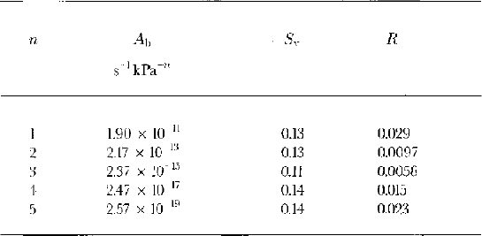
The optimal values of A, found by minimizing Expression (5) for different values of n, are listed in Table 2 together with the normalized root-mean-square error S v and the length R of the sum of the error vectors. Only winter measurements obtained from repeated surveying of markers with time intervals larger than 1 month were used in the calculations leading to the values in Table 2. A number of velocity estimates based on repeated surveying with a time interval of 3–4 days were not used, since the errors of the resulting velocity gradients were considered too large. For markers surveyed more than twice, averaged velocities were used.
Values of A b, S v and R for different values of n
In Figure 2 the value of R
is shown as a function of n. As can be seen, R
is a convex (concave upward) function of n with a minimum at
n = 3, suggesting that n = 3
is the optimal estimate of n. If N random
vectors having length l are added together, their sum will, on
average, have length ![]() . The medial
length of Ri was about 0.18 and N
= 39, so that a pure statistical variation is expected to give
R ≈ 0.18/
. The medial
length of Ri was about 0.18 and N
= 39, so that a pure statistical variation is expected to give
R ≈ 0.18/ ![]() = 0.016, a number almost
twice as large as the value of R obtained for
n = 3. This is only a rough estimate of the
contribution of random errors to the length of R, since not all the vectors
Ri had the same lengths. A simple estimate
of the errors involved can be obtained by using different numbers of marker
velocities to calculate the variation of R with respect to
n. Several calculations made by using only 80% of
the measured velocity vectors revealed that although the shape of the
R(n) curve changes somewhat as different
subsets of available measurements are used, the minimum of the curve is always
found for n = 3.
= 0.016, a number almost
twice as large as the value of R obtained for
n = 3. This is only a rough estimate of the
contribution of random errors to the length of R, since not all the vectors
Ri had the same lengths. A simple estimate
of the errors involved can be obtained by using different numbers of marker
velocities to calculate the variation of R with respect to
n. Several calculations made by using only 80% of
the measured velocity vectors revealed that although the shape of the
R(n) curve changes somewhat as different
subsets of available measurements are used, the minimum of the curve is always
found for n = 3.
R as a function of the parameter n in Glen’s flow law. R is the magnitude of the sum over all error vectors Ri, and is defined in the text. The minimum of R is reached for n = 3, indicating that the best overall agreement between measured and calculated surface velocities is obtained for that value of n.

For n = 3 the value of A that gives the best overall fit between calculated and measured winter velocities is A = 2.37 × 10⁻¹⁵ s−1 kPa−3. This value is almost three times smaller than the value recommended by Reference PatersonPaterson, 1994, which is A = 6.8 × 10⁻¹⁵ s−1 kPa−3. Including basal sliding in the numerical model would lead to an even smaller optimal value for A and thus make this discrepancy larger. One does not have to resort to a fully 3-D numerical model to realize that the recommended value of A = 6.8 × 10⁻¹⁵ s−1 kPa−3 is much too large for Unteraargletscher. Down-glacier of the confluence area the geometry of Unteraargletscher is relatively simple and can be approximately described as a parabolic channel with an aspect ratio of about 2, a slope close to 4° and a thickness of about 300 m. Using the form factors listed in Reference GudmundssonGudmundsson (1997a) indicates that the value of A must be reduced by at least a factor of two from Patersons’s recommended value if calculated medial flow velocities are to be similar to the observed winter-surface velocities.
Spatial error distribution
The variation of the sum of the error vectors with n shown in Figure 2 gives no indication of the spatial variation of the error vectors across the confluence area. Only if the lengths and the orientations of the error vectors are randomly distributed can it be concluded that the numerical model is free of systematic errors and that Glen’s flow law represents an appropriate rheological description of the ice of the confluence.
The error vectors Ri for n = 1, n = 3 and n = 5 can be seen in Figure 3. In addition, the normalized projection (P i) of the error vectors Ri along the measured flow direction defined as

is shown as a diamond symbol.
Relative discrepancy between measured and calculated surface
velocities for n = 1 (a), n = 3 (b) and n = 5
(c). Vectors represent a vector quantity
Ri defined by ![]() , where fA
is defined in the text. Subscript “i” refers to the
ith marker.
, where fA
is defined in the text. Subscript “i” refers to the
ith marker. ![]() are measured
velocities if markers, and
are measured
velocities if markers, and ![]() are calculated
velocities. The size of the diamond symbols is proportional to the
length of Pi, defined as the projection of
Ri on
are calculated
velocities. The size of the diamond symbols is proportional to the
length of Pi, defined as the projection of
Ri on ![]() (Equation (10)).
Coordinates are in meters and correspond to those of the official
Swiss coordinate system. North points upward.
(Equation (10)).
Coordinates are in meters and correspond to those of the official
Swiss coordinate system. North points upward.

Markers along two profiles across Lauteraar- and Finsteraargletscher above the confluence, and a profile across the Unteraargletscher below the confluence area, were measured with rather short time intervals of approximately 4 days. The associated measurement errors in the velocities are correspondingly large. Since the surveying errors are estimated to be about 3 cm, the errors of the velocities are about 4 m a−1. On the other hand, markers along the center line down-glacier from the junction point and along two lines from the marginal zones of the confluence towards its center, were measured repeatedly with time intervals of approximately 40 days, leading to much smaller measurement errors. In what follows, the discussion of the spatial variation of the error vectors will be limited to those markers for which long-interval measurements were available.
For n = 1 (Fig. 3a) the largest error vectors are found at the northern margin of the confluence. The error vectors point approximately in the flow direction. The (scaled) calculated velocities are therefore, at that location, smaller than the measured ones. For the marker closest to the junction point the situation is reversed.
For n = 3 (Fig. 3b) the error vectors at the northern and southern margins also point more or less in the flow direction but their magnitudes are overall somewhat smaller than in Figure 3a. For n = 5 (Fig. 3c) the magnitudes of the error vectors close to the northern margins decrease even further with respect to Figure 3a, but towards the southern margin the error vectors in Figure 3c are larger than in Figures 3a and b. The error vectors lying closest to the junction point in a direction almost exactly opposite to the direction of flow for all three values of n. The magnitudes of the error vectors in this area increase with increasing n.
For all values of n there is a systematic variation in both the direction and the magnitude of the error vectors across the confluence area. This is small enough, however, that it can only be seen at those locations where accurate estimates of the surface velocities, based on repeated surveying over a period of several months, are available. For n = 3 the errors are distributed almost symmetrically about the medial line. Calculating the error vectors for further values of n revealed that for n < 3 the errors tend to be larger along the northern than the southern margin; for n > 3 the situation is reversed. For n = 5 the only significant errors are close to the junction point and at the southern margin, but there is still a clear tendency for calculated marginal velocities to be smaller than measured ones.
Despite the non-randomness of the error vectors, their magnitudes are usually less than about 15%, an accuracy that is probably sufficient for most modeling purposes. Since the general flow characteristics of the confluence area form the main focus of this study, an error of this magnitude is considered acceptable.
General Properties of Calculated Flow Fields
Velocities
The calculated horizontal velocity distribution along the surface for n = 3 and A = 2.37 × 10¹⁵ a1kPa3 is shown in Figure 4a. The corresponding vertical velocity distribution can be seen in Figure 4b. The 3-D distribution of the vertical velocities is depicted in Figures 5 and 6 as isosurfaces of constant velocity for n = 1 and n = 3, respectively.
(a) Calculated horizontal surface velocities (vectors) and calculated horizontal speeds (contour lines). Comparing this velocity distribution with measured winter velocities (see Reference Gudmundsson., Iken. and Funk.Gudmundsson and others, 1997, fig. 5) reveals a good qualitative agreement. (b) Vertical velocities. The five flow features discussed in the text are indicated by Nos. 1–5. The values of the flow-law parameters are n = 3 and A = 2.37 × 10⁻¹⁵ s−1 kPa−3. Units are m a−1.

Isosurfaces if vertical velocities vz for A= 1.90 × 10¹¹ s−1 kPa−1 and n = 1. Vertical surface velocities are generally positive. A narrow zone of negative vertical velocities stretches from the junction point (J) down the whole Unteraargletscher. The downward movement if ice is particularly large in the vicinity of J. North is approximately to the right.

Isosurfaces of vertical velocities vz, for A = 2.37 × 10¹⁵ s−1 kPa−3 and n = 3.

Figure 4a shows a good qualitative agreement with measured surface-winter velocities (Reference Gudmundsson., Iken. and Funk.Gudmundsson and others, 1997, fig. 5). The calculated velocity distribution has a local maximum close to the center of the confluence, as do the measured winter velocities. Measured summer velocities do not have a maximum at this location (Reference Gudmundsson., Iken. and Funk.Gudmundsson and others, 1997, fig. 7). The calculated surface velocities of Finsteraargletscher are larger than those of Lauteraargletscher, decrease somewhat as both tributaries enter the confluence, and then increase again. All these qualitative aspects of the calculated velocity pattern are found in the measured velocity fields (Reference Gudmundsson., Iken. and Funk.Gudmundsson and others, 1997, fig. 5).
As seen in Figures 4b, 5 and 6, the numerical model predicts a complicated spatial pattern of vertical velocity distribution across the surface and with depth for both n = 1 and n = 3. Almost no direct measurements of vertical velocities during the winter period are available, as such measurements have proven logistically difficult to make. In addition, information on the vertical velocity distribution has been considered to be of secondary importance for model calibration. This opinion may be subject to change. As discussed in detail below, it appears that the effects both of local topography (having spatial scales of a few hundred meters) and of the convergence of the two tributaries on the flow field can be seen most clearly in the spatial variation in vertical velocities across the surface.
Identification and listing if noticeable flow features if the vertical velocity pattern
A number of conspicuous flow features of the vertical velocity distribution can be identified (Figs 4b, 5 and 6). These flow features may be listed as follows: (1) Around the junction point (J in Fig. 4b), there is a roughly semicircularly shaped zone with a radius of about 200 m of strongly negative (downward-oriented) surface velocities. (2) Close to the southern and northern margins of the confluence area two semicircular zones with positive vertical velocities can be seen. (3) Along a well-defined strip about 100–150 m wide down-glacier from flow feature 1, velocities are negative with maximum modulus of about 3 m a−1. (4) Down-glacier of the confluence area, parallel with and to the south and north of flow feature 3, a zone of positive velocities of up to 2 m a−1 can be identified. (5) A zone of positive vertical velocities is situated south of flow feature 1, and there is an indication of a similar zone to the north side of flaw feature 1, although this is not as clearly evident in Figure 4b.
Vertical flow feature 1
On the basis of the 2-D map-plane model developed and analyzed in Reference GudmundssonGudmundsson, 1997b, it is predicted that the abrupt change in boundary conditions at the junction point (J) leads to the formation of a surface depression located slightly down-glacier of J. The spatial size of the surface depression depends primarily on the value of n, decreasing in size as n increases.
The semicircular zone of highly negative vertical velocities (Figs 4b, 5 and 6) close to J does coincide with a strongly localized surface depression found in nature. This surface depression exists in the numerical model, but is not accurately described by it due to the coarseness of the FE mesh. It does not, as might be expected, give rise to positive vertical velocities along the surface as ice from the sides flows towards the depression to fill it. Instead the surface velocities are downward-oriented, suggesting that the surface depression results from the flow anomaly. A flow anomaly of this type has been predicted to be an essential feature of ice flow at all glacier confluence areas.
The “pressure drop” observed in the 2-D map-plane models (Reference GudmundssonGudmundsson, 1997b) is associated with the sharp velocity increase along the medial line at the junction point, which in turn is caused by the abrupt change in boundary conditions at that location. This pressure drop, which would lead to a surface depression of the type observed on Unteraargletscher, is related to the overall changes in flow regime as ice enters a confluence area. In this respect, the 3-D model confirms the conclusions drawn from the 2-D map model. Evidently, the ice flows faster away from the junction point in the down-glacier direction than it can flow laterally towards it, unless transverse gradients are set up, which then drive the ice towards the junction point.
The 2-D map-plane model predicts not only a localized surface depression close to the junction point, but also two broad surface bulges along the sides of the confluence. As discussed below, flow features 2 presumably represent the upward flow needed to maintain these bulges.
Calculated horizontal and vertical velocities along a profile from the junction point in the down-glacier direction are shown in Figure 7. This may be compared with Figure 4a in Reference GudmundssonGudmundsson, 1997b which is based on the 2-D map-plane model. The increase in velocities at the junction point in Figure 7 is sharp and becomes sharper with increasing n. Consequently, the strain rates and the deviatoric stresses are large. The FE mesh is, however, too coarse to give are exact estimate of the vertical velocities, as can be seen from the fact that the maximum of the vertical velocities is obtained at the FE node lying closest to J. A further mesh refinement would presumably move the maximum even closer to J and give larger negative values. Calculations with a coarser mesh (2800 elements instead of 6424) indeed showed that the position and the magnitude of this maximum depend on the level of mesh refinement. On the other hand, the slope of the horizontal velocity profile (Fig. 7) did not depend significantly on the number of elements used. There is also a tendency for the zone to become more localized with increasing n (Fig. 7), but the coarseness of the FE mesh makes it difficult to make a definitive statement in this respect.
Calculated horizontal (vx) and vertical (vx) velocity profiles along the surface from the junction point (J) towards the center of the confluence. The profile is approximately along a flowline. As discussed in the text, the velocity drop in vz seen on the left is related to the overall dynamics of the confluence, and leads to the formation of an observed local surface depression. Negative velocities further away from J are, on the other hand, associated with disintegration of the medial moraine caused by its higher than average elevation with respect to the surrounding ice. Symbols represent values at FE nodes.

Around the junction point, the maximum of v z, as a function of depth, is found at the surface. Several hundred meters further down-glacier (close to the location of a number of boreholes drilled in autumn 1991) the maximum is not at the surface but at a depth corresponding approximately to one-half of the glacier thickness. Even further down-glacier the amplitude of the vertical velocity feature becomes progressively smaller and eventually disappears. Below the confluence center the glacier has adjusted to the new bed geometry, and the divergence of the flowlines over the depth, and the associated vertical velocities, are thus strongly reduced in amplitude.
Vertical flow features 2
On the north and south sides of the confluence, diametrically opposite to the negative vertical velocity anomaly at the junction point, one finds two positive vertical velocity features. There are no apparent changes in local bedrock geometry or ice thickness that could cause these features. In fact, the features are associated with higher than average elevations which by themselves would lead to downward movements. The most likely explanation is that these features are related to the general flow dynamics of the confluence in a manner similar to flow feature 1. These features are expected on the basis of the 2-D map-plane model analyzed in Reference GudmundssonGudmundsson, 1997b.
Vertical flow feature 3
The longitudinal zone of downward velocities (flow feature 3) coincides exactly with the medial moraine. The ice-cored medial moraine rises about 10–18 m above its surrounding. This higher than average elevation with respect to the surrounding ice must lead to a viscous relaxation of the medial moraine and a corresponding downward movement of its ice. These negative vertical velocities are an expression of the transverse diffusion of the medial moraine. There are no in situ measurements of vertical velocities along the medial moraine, but the lateral disintegration as expressed through a small horizontal divergence of the horizontal velocities has been observed in surface velocities extracted from aerial photographs (Reference Gudmundsson., Iken. and Funk.Gudmundsson and others, 1997). The vertical extent of the negative velocities can be seen in Figures 5 and 6, where the feature is depicted as deep-red-colored isosurface which extends from J down the whole length of the glacier.
Vertical flow feature 4
On both adjacent sides of the medial moraine, vertical velocities are positive. To the south of the moraine (left in Figs 5 and 6) the upward movements are especially large. There the ice is practically free from supra-glacier debris which covers the medial moraine. There is another, considerably smaller medial moraine situated further south. As a result, differential ablation leads to the formation of a slight longitudinally aligned surface depression (“inverted” medial moraine). The surface depression, together with the overall longitudinal compression resulting from the general velocity decrease in the down-glacier direction, is responsible for these positive velocities. The corresponding vertical extension at the surface has been detected in measured velocity fields (Reference Gudmundsson., Iken. and Funk.Gudmundsson and others, 1997). The whole of the glaciated area covered by the numerical model is located within the ablation zone. Predicted negative vertical velocities along some parts of the surface stand in no contradiction with this fact.
Vertical flow features 5
The mechanism explaining the generation of the positive vertical velocities on the northwest side of Finsteraargletscher, about 500 m upward from the junction point, and the considerably smaller velocity feature on the southwest side of Lauteraargletscher is not clear. A possible explanation is that these features are related to lateral flow of the marginal ice, which at these locations rises somewhat above the average surrounding surface.
Strain rates
The isosurfaces of constant vertical strain rates are displayed in Figures 8 and 9 for n = 1 and n = 3, respectively, and for A from Table 2. Negative strain rates correspond to vertical compression, and positive values to vertical extension.
Vertical strain-rate isosurfaces for n = 1. Vertical strain rates are generally positive (extension). The purple-colored “tube” represents ice being compressed vertically as a result of the weight of the overlying medial moraine. Further south, a similarly shaped yellow-and-orange-colored tube can be seen, which, as explained in the text, is related to the existence if an “inverted” medial moraine directly above it. North is approximately to the right.

Vertical strain-rate isosurfaces for n = 3. The strain-rate distribution is qualitatively similar to the one seen in Figure 8 calculated for n = 1, but quantitatively large differences can be observed.

The vertical compression resulting from the ice-cored medial moraine can be seen clearly in Figure 8 as an isosurface in the form of a longitudinally aligned cylinder, referred to as “the tube”. This tube is also evident in Figure 9, although less so. Velocity feature 3 is found along the surface area above this tube of vertical compression. Underneath the medial moraine (Figs 8 and 9), the isosurface marking the boundary between positive and negative vertical strain rates (shown in red) is displaced towards the surface with respect to the surrounding ice. Vertical extension is particularly large directly south and north of the medial moraine below velocity feature 4.
Outside of the region directly affected by the medial moraine, vertical strain rates are predominantly positive, as expected for an ablation area. The most noticeable exception to this general rule is found within the confluence area close to the junction point (Fig. 10). As seen in Figures 8 and 9, the tube dips downwards in the up-glacier direction, and reappears at the surface directly down-glacier of the junction point. The complexity of the vertical strain-rate variation with depth along the center line of the confluence is evident in Figure 11. Vertical compression of the basal ice is confined to the area where ice thicknesses increase in the flow direction (Figs 8 and 11). Although the average strain over the depth must be positive where ice thickness increases in flow direction, the no-slip boundary condition forces the vertical velocity component to become zero along the glacier bed, with the result that the zone of vertical compression forms directly above the bed. This at first sight somewhat counter-intuitive point is explained in more detail in Reference GudmundssonGudmundsson, 1997b
Vertical strain-rate isosurfaces of the confluence area for n = 3, as seen from below the confluence area. The overall flow direction of Unteraargletscher is into the picture plane. Gray arrows indicate flow directions of Finsteraar- and Lauteraargletscher. Vertical strain rates are predominantly negative (compression). A zone of particularly strong vertical compression (–0.15 to –0.05 a−1) is seen extending downward (upward in the figure) from the Junction point (J). Field measurements (Reference Gudmundsson., Iken. and Funk.Gudmundsson and others, 1997) have demonstrated the existence of this zone.

Vertical strain rates ![]() for A = 2.37
× 10−15 s−1
kPa−3 and n = 3, across a longitudinal
section from the junction point (J) towards the center if the
confluence. B indicates the position of a borehole (shown as a thick
vertical line) in which vertical strain rates were measured. The
section shown is approximately along a flowline. Extension is
positive and compression negative. Below point B, strain rates are
positive over about the upper two-thirds of the glacier thickness,
with maximum strain rates of approximately 0.03 a1. With
increasing depth the bed strain rates become negative, reaching a
maximum value if about –0.05 a−1 at bed.
Comparison with the measured vertical strain-rate profile (see Reference Gudmundsson., Iken. and Funk.Gudmundsson and others, 1997,
fig. 4) shows a good qualitative agreement. It is difficult to give
an accurate estimate if the quantitative agreement between modeled
and measured values, because of the small number if available data
points.
for A = 2.37
× 10−15 s−1
kPa−3 and n = 3, across a longitudinal
section from the junction point (J) towards the center if the
confluence. B indicates the position of a borehole (shown as a thick
vertical line) in which vertical strain rates were measured. The
section shown is approximately along a flowline. Extension is
positive and compression negative. Below point B, strain rates are
positive over about the upper two-thirds of the glacier thickness,
with maximum strain rates of approximately 0.03 a1. With
increasing depth the bed strain rates become negative, reaching a
maximum value if about –0.05 a−1 at bed.
Comparison with the measured vertical strain-rate profile (see Reference Gudmundsson., Iken. and Funk.Gudmundsson and others, 1997,
fig. 4) shows a good qualitative agreement. It is difficult to give
an accurate estimate if the quantitative agreement between modeled
and measured values, because of the small number if available data
points.

The vertical strain-rate variation with depth has been measured in a borehole at
one location within the confluence (see Reference Gudmundsson., Iken. and Funk.Gudmundsson and others, 1997, fig. 4). The location of the borehole
is labeled B in Figure 11. According to
measurements, ![]() is positive at
the surface, decreases with increasing depth, becomes negative at a depth
corresponding to about three-fifths of the glacier thickness and becomes
increasingly negative towards the bottom. The extension towards the surface, and
the compression towards the bottom are nicely reproduced by the numerical model
(Fig. 11). For n
= 3 the numerical model gives values which are also in reasonably good
agreement with measurements. For example, in the vicinity of the bedrock the
model gives
is positive at
the surface, decreases with increasing depth, becomes negative at a depth
corresponding to about three-fifths of the glacier thickness and becomes
increasingly negative towards the bottom. The extension towards the surface, and
the compression towards the bottom are nicely reproduced by the numerical model
(Fig. 11). For n
= 3 the numerical model gives values which are also in reasonably good
agreement with measurements. For example, in the vicinity of the bedrock the
model gives ![]() , whereas
measurements give
, whereas
measurements give ![]() . Since the
measured vertical strain-rate variation is based on only four velocity
measurements, the qualitative agreement is within observational errors. Vertical
compression of the basal ice has been measured only at the confluence area.
Measurements made in spring 1997 in boreholes about 2 km down-glacier from the
confluence area indicate vertical extension throughout the thickness (Reference GudmundssonGudmundsson, submitted).
. Since the
measured vertical strain-rate variation is based on only four velocity
measurements, the qualitative agreement is within observational errors. Vertical
compression of the basal ice has been measured only at the confluence area.
Measurements made in spring 1997 in boreholes about 2 km down-glacier from the
confluence area indicate vertical extension throughout the thickness (Reference GudmundssonGudmundsson, submitted).
Implications for Glacier Abrasion
The potential for glacier abrasion is thought to depend strongly on the debris content and the flow characteristics of the basal ice (e.g. Reference HalletHallet, 1981). Although not specifically aimed at evaluating the implications for glacier abrasion, the above analysis demonstrates that the characteristics of the flow field of a confluence are such that the basal ice will be compressed vertically, which is a prerequisite for glacier abrasion to take place. An additional implication for glacier abrasion stems from the fact that along the surface close to the junction point, vertical velocities will, in general, be oriented downward. Surficial debris may thus be expected to be transferred with the ice towards the glacier bed. This will affect the debris concentration of the basal ice, but the quantitative effects on abrasion are difficult to predict.
Medial Moraine
Because vertical velocities along the ice-cored medial moraine are always negative, the dynamics of the confluence cannot be considered directly responsible for its creation. Neither the change in boundary conditions at the junction point nor the converging of the two tributaries piles up ice. On the contrary, they lead to the formation of a strongly localized surface depression. The differential ablation of the debris-covered marginal ice of the two tributaries and the adjacent clean ice is the sole cause of the moraine ridge. Consequently, it is only at some distance below the junction point, where the effect of differential ablation starts to dominate the strong downward movements, that the ice-cored medial moraine starts to form. The surface debris does not immediately give rise to a medial moraine as described by Reference Gomez and Small.Gomez and Small (1985) in their model of ice-stream interaction moraines. Without surficial detritus covering the marginal zones of the tributaries where they coalesce, the advection of the surface depression initially formed at the junction point would lead to the formation of a longitudinally aligned depression, and not to a medial moraine that rises above the surrounding ice.
The magnitude of the calculated negative vertical velocities along the medial moraine depends strongly on n and decreases with increasing n. This is because the driving stresses associated with the transverse diffusion of the medial moraine are much smaller than the driving stresses responsible for the bulk of the glacier flow. Using A from Table 2 gives, for a pure shear stress of approximately 80 kPa, the same shear strain rate for all values of n, a consequence of the particular procedure used for determining the values in the table. Therefore the calculated values of the vertical movements of the medial moraine must be viewed with caution. Detailed measurements of the vertical and the transverse velocities across the medial moraine could give information on the rheological behavior of ice at stresses far less than the typical driving stresses.
Summary
A fully 3-D non-linear model with only two adjustable parameters (A and n) was used to calculate the flow field of Unteraargletscher. A quantitative comparison of measured and calculated winter velocities revealed systematic errors for all values of n. The errors were, however, within acceptable limits. The cause of the systematic errors is not clear. It may be that the flow law itself is not an adequate description of the mechanical properties of glacier ice, but other explanations are also possible. The applied boundary conditions (no slip) would, for example, be wrong if the glacier should slide during winter.
The overall qualitative agreement of the numerical calculations with field observations is good. All of the main features of the observed flow were reproduced by the calculations. No adjustment of parameters was necessary to obtain this agreement. The general conclusions reached with the help of the idealized 2-D models were confirmed by the 3-D calculations. One of the surprising results of the 3-D calculations, not evident from previous conceptual 2-D models, is that in the immediate vicinity of the junction point the surface ice is compressed in the vertical direction. Only somewhat further down-glacier from the junction do vertical surface strain rates become positive.
Figure 12 summarizes the velocity features found with the 3-D model, excluding those features resulting from surface processes. The plus signs denote upward movements, and the minus signs downward movements. The solid lines give the approximate spatial extent of features that were seen in the 3-D model, and which can also be understood with the help of 2-D conceptual models (Reference GudmundssonGudmundsson, 1997b). These features are considered universal, in the sense that they should be found in all confluence areas. The dashed lines indicate zones which were found with the 3-D model but possibly caused by some unique features of the geometry of the particular confluence modeled.
Vertical velocity features of the 3-D model. Plus symbols denote zones of larger than average upward velocities, and minus symbols a zone of downward velocities. Zones marked by dashed lines represent vertical velocity features of the 3-D model which are not produced by conceptual 2-D models.

Flow features 1 and 2 listed above are related to the overall dynamics of the confluence area. These flow features lead to the formation of the associated surface undulations and are not caused by them. Flow features 3 and 4, on the other hand, represent responses to surface undulations which themselves are maintained by differential ablation. Hence, flow features 3 and 4 are only indirectly related to the dynamics of a confluence area and one could, for example, envision a confluence where lack of surficial debris would make it impossible for flow features 3 and 4 to form. The role of flow features 5 is not clear. They may be caused by some unidentified general properties of ice flow at a confluence, or simply by the particular geometry of Unteraargletscher.
The ice-cored medial moraine is not generated directly by the flow dynamics of the confluence. Differential ablation is the sole cause of the moraine ridge. The ridge starts to form at some distance down-glacier from the junction point where the differential ablation more than compensates the downward vertical movements at the junction point.
Acknowledgements
The work was supported by Swiss Science Foundation grant No. 20-29619.90. The assistance and support given by A. Iken during this work is gratefully acknowledged. Numerous discussions with M. Funk and S. Wagner, and valuable comments by K. Hutter, U. H. Fischer and R. Greve resulted in considerable improvements to an earlier version of the manuscript.


