

Introduction
With the potential to raise sea level by 6 m, the marine-based West Antarctic ice sheet (WAIS) has been the subject of much study since the late 1960s, when concerns about its long-term stability were first raised (Reference MercerMercer, 1968). In particular, much of the research focus has been on the area of the ice sheet drained by the Ross ice streams (Ice Streams A, C, D, E, F and Whillans Ice Stream) (Reference Alley, Bindschadler, Alley and BindschadlerAlley and Bindschadler, 2001). The grounding line, the point where the ice sheet loses contact with the bed and begins to float, has retreated in this area by 1300 km over the course of the Holocene (Reference Conway, Hall, Denton, Gades and WaddingtonConway and others, 1999). Although early results suggested this area of the ice sheet was still thinning (Reference Shabtaie and BentleyShabtaie and Bentley, 1987), recent results show that this sector of the ice sheet is now thickening (Reference Bougamont, Tulaczyk and JoughinJoughin and Tulaczyk, 2002), in large part because of the stagnation of Ice Stream C within the last two centuries (Reference Retzlaff and BentleyRetzlaff and Bentley, 1993).
Although concern about a catastrophic collapse of the WAIS is beginning to abate (Reference Alley, Bindschadler, Alley and BindschadlerAlley and Bindschadler, 2001), flow in the Ross ice streams has undergone and continues to undergo change. Flow stripes preserved in the Ross Ice Shelf record a history of highly variable flow over the last millennium (Reference Fahnestock, Scambos, Bindschadler and KvaranFahnestock and others, 2000). Over the period 1974–97, Whillans Ice Stream underwent a 23% deceleration (Reference Bougamont, Tulaczyk and JoughinJoughin and others, 2002). On much shorter time-scales, recent results indicate that the areas just above the grounding lines of Whillans Ice Stream and Ice Stream D undergo large variations in speed (<50%) over what is presumed to be the course of the cycle of ocean tides in the Ross Sea (Reference Anandakrishnan, Voigt, Alley and KingAnandakrishnan and others, 2003; Reference Bindschadler, Vornberger, King and PadmanBindschadler and others, 2003). Understanding the dynamic variability of these ice streams is important to understanding the future contribution of West Antarctica to sea-level rise. Furthermore, internal dynamic instabilities in marine-based ice sheets are believed to have been a potential forcing in past climate change (e.g. Heinrich events) (Reference MacAyealMacAyeal, 1993a). Thus, the WAIS represents an important “natural laboratory” with which to understand the processes leading to paleo-ice-sheet instabilities.
Glaciological setting and modeling efforts
The ice streams flow at roughly 400 m a–1 despite having surface slopes and hence driving stresses orders of magnitude less than typical outlet glaciers (e.g. Byrd Glacier, Antarctica, or Jakobshavn Isbræ, Greenland). This high velocity is enabled by a several-meter thick layer of water-saturated dilatant till with a porosity that is capable of being increased, or dilated, by shear deformation (Reference Alley, Blankenship, Bentley and RooneyBlankenship and others, 1987). While there has been evolution in the ideas concerning how this till should be treated in models (e.g. as a viscous deforming till (Reference Alley, Blankenship, Bentley and RooneyAlley and others, 1987; Reference Kamb, Alley and BindschadlerKamb, 2001) or as a weak plastic bed (Reference KambKamb, 1991; Reference Tulaczyk and Kamb and EngelhardtTulaczyk and others, 2000a, b)), all ideas embrace basal water as an essential ingredient for the fast flow of these ice streams.
Early estimates predicted relatively large (~20 mm a–1) basal melt beneath the Ross ice streams (Reference RoseRose, 1979; Reference Shabtaie and BentleyShabtaie and Bentley, 1987). Since then several studies (Reference Whillans, Bentley and van der VeenWhillans and others, 2001) have shown that ice-stream shear margins can support much of the driving stress, shifting the shear heating available to melt ice to the margins (Reference RaymondRaymond, 2000). Studies investigating the heat balance of ice streams have found that, at least in some well-lubricated areas, it is difficult to sustain basal melting (Reference Hulbe and MacAyealHulbe and MacAyeal, 1999; Reference RaymondRaymond, 2000). A modeling study has shown that, in the case of an undrained bed, Ice Stream C should rapidly freeze to the bed (Reference Bougamont, Tulaczyk and JoughinBougamont and others, 2003b). Other studies have suggested that the ice-stream tributaries and catchments provide sufficient melt to perhaps offset downstream freezing and enable fast motion (Reference Parizek, Alley, Anandakrishnan and ConwayParizek and others, 2002; Reference Bougamont, Tulaczyk and JoughinJoughin and others, 2003).
There are a number of feedbacks in a full thermodynamic ice-sheet model between ice-stream speed, basal lubrication and basal melt generation, making it difficult to reproduce both the current velocity and temperature distribution (Reference Hulbe and MacAyealHulbe and MacAyeal, 1999). Reference Bougamont, Tulaczyk and JoughinJoughin and others (2003) used measured velocities to estimate the basal melt beneath Whillans Ice Stream and Ice Stream C. The temperature model they used, however, did not include the effects of horizontal advection. Instead, they artificially adjusted the accumulation rate to match observed temperature profiles. The limitation of this method is that a parameter from a fit at one location is applied to the entire ice-stream catchment. A significant improvement can be made by using the measured velocity field to represent advective and heat-generation terms in numerical solutions for the temperature distribution and basal melt. Reference Vogel, Tulaczyk and JoughinVogel and others (2003) used measured velocities with a flowline model to include the effects of horizontal advection and achieved good agreement with measured temperature profiles without any fitting procedure. Here we use this approach over the catchments of Whillans Ice Stream and Ice Streams A, C and D. In addition, we improve upon past estimates by including internal strain heating and by using the velocity field to invert for the basal shear stress (e.g. Reference MacAyealMacAyeal, 1993b), which is needed to estimate basal shear heating. The remainder of this paper describes and discusses the results of this effort.
Methods
The basal melt rate, m r, can be estimated using (Reference PatersonPaterson, 1994)
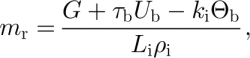
where G is the geothermal heat flux, τ b is the basal shear stress, U b is basal speed, k i is the thermal conductivity for ice, Θb is the basal temperature gradient, L i is the latent heat of fusion, and ρ i is the density of ice. The difficulty in applying this equation is in obtaining estimates of G, Θb and basal shear heating, τb U b. We note that this form of the shear heating term, bUb ; encompasses all mechanical heating at and beneath the bed due to the motion of the ice base, and can be interpreted to treat either sliding across an immobile plastic till slip surface or shear deformation within a finite layer of deforming material. The remainder of this section describes the data, models and assumptions that were used to estimate basal melt.
Geothermal heat flux
We used a spatially homogeneous value of G = 70 mW m–2 in all our estimates, which is the value that was determined from a borehole at Siple Dome (Engelhardt, in press). Previously, Reference Alley and BentleyAlley and Bentley (1988) estimated even higher heat flow (~80 mW m–2) from shallow borehole temperature measurements made on nearby ridge B/C. Temperature data from the deep borehole drilled at Byrd Station were used by Reference RoseRose (1979) to infer a lower geothermal flux of ~60 mW m–2. The sensitivity of the basal melting estimate to G is approximately 1mm a–1 change in m r for a change in G of 10 mW m–2. This level of sensitivity is consistent with results reported by Reference HulbeHulbe (1998). Although we do not rule out the presence of localized heat sources (e.g. Reference Blankenship, Bell, Hodge, Brozena, Behrendt and FinnBlankenship and others, 1993), we ignore such effects since the locations and magnitudes of any such sources are poorly constrained.
Temperature model
We solved for the temperature within the ice column lying atop a homogeneous bedrock slab with depth equal to one ice thickness. Following common practice (e.g. Reference HulbeHulbe, 1998), we neglect horizontal diffusion so that temperature within the ice is determined by the following simplified statement of thermal energy conservation:
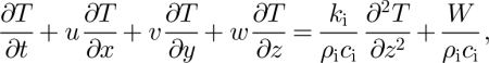
where u, υ and w are respectively the x, y and z velocity components, and c i is the thermal heat capacity for ice. Strain heating within the ice column is given by W in Equation (2). In the underlying bedrock we solve
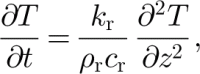
which includes only thermal diffusion. These equations disregard possible heat advection due to groundwater flow, which we expect to be small.
The boundary condition at the ice-sheet surface is the specification of a surface temperature taken to be the mean annual surface temperature (Reference ComisoComiso, 1994, Reference Blankenship, Bentley, Rooney and Alley2000). At the bottom of the bedrock layer, the boundary condition is
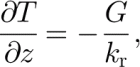
where, as mentioned previously, G is the geothermal flux and k r is the conductivity estimated for bedrock below the zone of any weathered or altered layers.
If the ice is frozen to the bed, Equations (2) and (3) are solved for temperature in the ice/bedrock column, subject to the upper- and lower-boundary conditions. If the bed is wet, Equations (2) and (3) are solved individually with the additional boundary condition that temperature equals the pressure-melting point, T pmp, at the ice/bedrock interface.
The basal temperature gradient is an internal variable of the model described above, and is determined by solving Equations (2) and (3). For flexibility, an irregular grid is used to solve the numerical forms of the model equations, which allows variable horizontal resolution. Based on a simple analysis of the ice velocity data, to be described below, each node in the map view of the domain of interest is designated as an ice-sheet, tributary or ice-stream node. Slow-moving regions (e.g. ~25 m a–1) were designated as ice-sheet nodes and fast-moving regions (~200 m a–1) as ice-stream nodes. Nodes moving at intermediate speeds (~25–200 m a–1) were classified as tributary nodes. While subjective, this simple discrimination between various regimes of ice flow follows common practice, and reflects best available experience in associating flow velocity regimes with ice-sheet flow styles. In Figure 1, the ice streams generally correspond to the red areas, the tributaries to the blue areas, and the ice sheet to the brown-green areas. Following MacAyeal (unpublished information, 1997), we recast Equations (2) and (3) to use a contour-following vertical coordinate and then solve them numerically.
Ice-flow speed (colors) (Reference Bougamont, Tulaczyk and JoughinJoughin and others, 2002) over radar imagery from the RADARSAT Antarctic Mapping Project mosaic (Reference JezekJezek, 2002). Flow speed at100 m a–1intervals is contoured with thin black lines. White vectors show subsampled velocity vectors in fast-moving areas. Catchment boundaries for individual ice streams are plotted with thick black lines. Red stars show borehole locations, and the blue star (FH shifted) shows a location discussed in the text.

We assume that most of the strain-heating rate is the result of vertical shear, W vert, within the column and lateral shear at the margins, W lat. Most of the heat from lateral shear is concentrated near the margin, and remains close to the margin even as it advects downstream. We assume that much of this heat, which is generated throughout the column, is advected across the grounding line before it has a significant effect on melt at the bed. Thus, we do not include W lat in our model, and consequently we may slightly underestimate melt near the margins.
For ice motion arising solely from vertical shear, the strain heating can be calculated as (Reference PatersonPaterson, 1994)
The problem with this expression is that it is based on the shallow-ice approximation and, in practice, it does not necessarily conserve energy when applied to real data because it is proportional to
![]() . For example, with this equation an ice sheet with a smooth surface would generate much less heat than one with a very bumpy surface with the same mean slope. This is because other stresses are ignored that tend to smooth out the vertical strain rate near the bed at scales less than several ice thicknesses (e.g. at short length scales ice velocity does not fluctuate as
. For example, with this equation an ice sheet with a smooth surface would generate much less heat than one with a very bumpy surface with the same mean slope. This is because other stresses are ignored that tend to smooth out the vertical strain rate near the bed at scales less than several ice thicknesses (e.g. at short length scales ice velocity does not fluctuate as
![]() (Reference Joughin, Tulaczyk, Bindschadler and PricePrice and others, 2002). Smoothing τd over several ice thicknesses potentially solves this problem, but it leaves the problems of what is the correct smoothing length to best conserve energy and smooth over sharp features such as shear margins.
(Reference Joughin, Tulaczyk, Bindschadler and PricePrice and others, 2002). Smoothing τd over several ice thicknesses potentially solves this problem, but it leaves the problems of what is the correct smoothing length to best conserve energy and smooth over sharp features such as shear margins.
Integration of Equation (5) over the ice thickness yields

for the total heat generated within the column. Since this expression is linear in τ d, fluctuations in the driving stress may lead to local errors, but energy is conserved along the length of a flowline, provided there is an independent estimate of Ū def. To estimate the heating within the column, we normalize the result from Equation (5) and multiply by the result from Equation (6). This may lead to errors in how the heating is distributed within the column, but unlike the direct application of Equation (5), energy should be conserved.
For the ice-sheet nodes in our model, we use the procedure just described to estimate the internal strain heating. For the tributary nodes, we partition the measured surface velocity into sliding and deformational components using the basal shear stress estimate. We then apply the above procedure using the basal shear stress in place of the driving stress to compute the strain heating. Since we use a shallow-ice approximation to partition the surface velocity into sliding and deformational components, we are subject to errors
![]() . Nevertheless, the combined basal shear heating and internal strain heating is capped at ~ U
measured τb. The main source of error relates to how we partition this fixed amount of heat generation between basal- and internal-shear heating. We expect that these types of errors tend to average out along flowlines. The sensitivity to errors in this assumption is described below. For the ice-stream nodes, we assume the vertical shear heating is negligible and ignore the lateral shear heating as described above.
. Nevertheless, the combined basal shear heating and internal strain heating is capped at ~ U
measured τb. The main source of error relates to how we partition this fixed amount of heat generation between basal- and internal-shear heating. We expect that these types of errors tend to average out along flowlines. The sensitivity to errors in this assumption is described below. For the ice-stream nodes, we assume the vertical shear heating is negligible and ignore the lateral shear heating as described above.
We rely largely on interferometric synthetic aperture radar (InSAR) measurements for the horizontal velocity (Fig. 1) (Reference Bougamont, Tulaczyk and JoughinJoughin and others, 2002). In areas where there are gaps in the measured velocity, we either interpolate, or use balance velocities (Reference Bamber, Vaughan and JoughinBamber and others, 2000). For the fast-moving tributary and ice-stream nodes, we assume there is significant sliding so that the flow velocity is constant throughout the ice column. At ice-sheet nodes where the velocity is depth-dependent, we compute the normalized variation of velocity with depth for internal deformation (Reference PatersonPaterson, 1994, p. 251). This function is then multiplied by the measured surface velocity to estimate the depth-dependent velocities.
Assuming a steady state, the vertical velocity for the ice-stream and tributary nodes is well represented as varying linearly from a value equal to the accumulation rate at the surface to zero at the bed (MacAyeal, unpublished information). In the case of sheet flow, a linearly varying vertical velocity does not strictly apply. In such cases, the vertical strain rate is sometimes modeled as constant above a shearing layer of thickness h, below which it falls off linearly to zero (Reference Dansgaard and JohnsenDansgaard and Johnsen, 1969). We applied this model to the ice-sheet nodes in our solution of Equation (2) with h equal to 16% of the ice thickness. Sensitivity to the shear layer thickness is described below.
We initialized the model with an analytical solution for T, which neglects horizontal advection (Reference ZotikovZotikov, 1986). With this model, temperature depends on the ice thickness (Fig. 2) (Reference Lythe and VaughanLythe and others, 2001) and the surface accumulation rate (Reference Giovinetto and ZwallyGiovinetto and Zwally, 2000). Figure 3 shows the initial basal temperature gradient. As part of the initialization process, it must be determined which nodes are melted and which frozen. We assume that a wet bed enables the fast motion of the ice streams and their tributaries, so the basal temperature at these nodes was fixed at T pmp. For ice-sheet nodes where the bed is frozen, we determine the bed temperature with the analytical solution in which G determines the basal temperature gradient. If the temperature is below the pressure-melting point, the initialization procedure designates the node as frozen. If the temperature is at or above the freezing point, then the node is considered melted and we initialize temperature by switching to the analytical solution for a wet bed (Reference ZotikovZotikov, 1986).
Ice thickness map used to model basal temperature gradient for the Ross ice streams and their catchments (Reference Lythe and VaughanLythe and others, 2001). Flow-speed contours at 100 m a–1 intervals (black) and at 50 m a–1 (white) show locations of the ice streams. Stars show borehole locations discussed in the text.

Basal temperature gradient computed from an analytical solution with no horizontal advection that was used to initialize the numerical solution. Flow-speed contours at 100 m a–1 intervals (black) and at 50 m a–1 (white) show locations of the ice streams. Stars show borehole locations discussed in the text.

During a model run, we test whether each ice-sheet node is frozen or melted at every time-step. We assume that beneath the ice sheet there is no flow of meltwater from adjacent nodes or local storage of meltwater so that a node freezes to the bed at any time-step when the basal temperature allows more upward conduction of heat than supplied by the geothermal heat flux. A frozen node becomes a melted node at any time-step where T equals or exceeds T pmp. Since our model lacks subglacial drainage, we do not allow melt generated at one node to freeze at another, and thus do not allow any basal accumulation beneath ice-sheet nodes. For the ice streams and tributaries, we assume an infinite reservoir of basal water so that the bed remains wet (e.g. we assume the presence of fast motion indicates a wet bed, where either freezing or melting may be occurring).
Although there was little change for most nodes after 7500 years, we ran the model for 15 000 years for each ice-stream catchment to achieve a steady state. We attribute this relatively rapid convergence, in part, to our initialization with the vertical advection solution. Because most of this interval falls within the Holocene, and is therefore subject to relatively stable surface temperatures, we ran the model with the surface temperatures fixed with time. Figure 4 shows the final temperature gradient from the model.
Basal temperature gradient, Θb, modeled to include the effect of horizontal advection. Flow-speed contours at 100 m a–1 intervals (black) and at 50 m a–1 (white) show locations of the ice streams. Stars show borehole locations discussed in the text.

Basal shear stress
We need the basal shear stress, τb, to determine the amount of basal shear heating that contributes to melt. A general slip law (Reference RaymondRaymond, 2000) gives the relationship between basal velocity and shear stress as
where the properties of the bed determine τ0 and m. Laboratory tests on samples of till retrieved from boreholes through the ice suggest that the till behaves as a weak plastic material (m → ∞) that fails under a few kPa of applied shear stress (Reference KambKamb, 1991; Reference Tulaczyk and Kamb and EngelhardtTulaczyk and others, 2000a). In this case, all the motion is accommodated by sliding at the ice–till interface. Alternatively, a linear viscous deforming bed (m = 1) is often considered as the source of fast weak-bed ice-stream motion (Reference Alley, Blankenship, Bentley and RooneyAlley and others, 1987; Reference Kamb, Alley and BindschadlerKamb, 2001). For comparison, a conventional hard-bed sliding law would have m = 2.
With a homogeneous till layer it is easy to parameterize the power-law sliding dependence for a plastic or viscous bed, but, in practice, heterogeneities at the bed lead to “sticky spots”, yielding a more complicated relationship between basal shear stress and flow speed (Reference AlleyAlley, 1993; Reference RaymondRaymond, 2000). Consequently, over scales greater than an ice thickness, even with a purely plastic or viscous till, the “effective” value of m that may best represent flow behavior might lie anywhere between 1 and ∞.
Reference MacAyeal, Bindschadler and ScambosMacAyeal and others (1995) assumed a viscous deforming bed, and used velocity data in an optimal-control-method inversion to estimate the basal shear stress beneath Ice Stream E (Reference MacAyealMacAyeal, 1993b). The same techniques can be used to implement an inversion routine for a weak plastic bed (Joughin and others, in press). The weak plastic till and the linear viscous till are the easiest models to invert for the basal shear stress, and together they bracket the range of expected m. While there are differences in the overall goodness of fit for each model, the basal shear stress distributions from inversions of each model do not differ drastically (e.g. both cases achieve force balance while matching the observed velocity). Thus, we expect to get a reasonable distribution of basal shear stress even if the model we invert differs slightly from reality (e.g. as from spatially variable m and τ0). We used the basal shear stress determined by these inversions (Joughin and others, in press) for the ice-stream and tributary nodes. At the ice-sheet nodes, we assumed τb = τd. Figure 5 shows the resulting distribution of basal shear stress for all nodes.
Basal shear stress for the Ross ice streams. Beneath the ice streams and tributaries, τb was determined from inversions constrained by the velocity data in Figure 1. For the slow-moving ice sheet, τb is assumed to equal τd. Flow-speed contours at 100 m a–1 intervals (black) and at 50 m a–1 (white) show locations of the ice streams. Stars show borehole locations discussed in the text.

Basal velocity
While the data shown in Figure 1 provide U s, the melt-rate calculations require basal velocity, U b. With the ice-stream nodes, there is little internal deformation, so we can assume U b ≈ U s. This assumption also applies to areas beneath the tributaries where the bed is weak. Where the bed is strong beneath the ice sheet and some tributaries, however, internal deformation yields a significant contribution to U s so that U s > U b. To compensate, we estimate the speed due to internal deformation for the tributary and ice-sheet nodes (Reference PatersonPaterson, 1994) and subtract it from U s to estimate U b: Since we use τb to compute the deformation velocity, this correction only has a significant effect in the regions where the bed is strong.
Results
Using the model described above, we estimated the basal temperature gradient and the melt rate beneath the Ross ice streams.
Basal temperature gradient
The basal temperature gradient modeled with horizontal advection (Fig. 4) differs markedly from that modeled with only vertical advection (Fig. 3). With the inclusion of strain heating, the bed beneath much of the ice sheet and tributaries is more prone to melting. In contrast, the ice streams are much more subject to freezing due to the addition of horizontal advection. The steepening of the gradient is most pronounced (e.g. blue regions in Fig. 4) where the ice thins rapidly as it moves from the deep interior to the shallow ice-stream beds (Reference Parizek, Alley, Anandakrishnan and ConwayParizek and others, 2002). Where the tributary beds are weak, horizontal advection can lead to changes in Θb that favor freezing. In other areas where the tributary beds are stronger, internal strain heating causes changes in Θb that promote melting.
The downstream area of Ice Stream C differs little between the models with and without horizontal advection. This is because Ice Stream C stopped roughly 150 years ago (Reference Retzlaff and BentleyRetzlaff and Bentley, 1993), and we have used post-stagnation velocities to model temperature. To examine conditions prior to the shutdown, we have used an ice-stream model (Reference MacAyealMacAyeal, 1989) to determine velocities that would roughly maintain the mass balance of the ice stream. Figure 6 shows the temperature gradient with active ice-stream velocities. As expected, the faster velocities cause the temperature gradient to decrease over much of the now stagnant area. There is a small area where there was little change or slight increase in the temperature gradient. This is because inaccuracies in the elevation data over some regions yield model velocities with flowlines that, when traced backward, originate on ridge B/C instead of the catchment interior. As a result, there is little thinning along these flowlines, leading to little change in the temperature gradient. Flow stripes visible in satellite imagery suggest the flowlines should indeed originate further inland, so it is likely that with our modeled velocity field the model overestimates Θb in the stagnant part of Ice Stream C. This is a good illustration of why measured velocities are preferable to modeled velocities.
Basal temperature gradient for Ice Stream C estimated using modeled velocity field for the downstream end. The modeled velocity is shown with contours at 100 m a–1 intervals (black) and at 50 m a–1 (white).

Borehole/model comparison
Boreholes drilled through the ice yield measured temperatures at several locations (see Fig. 1) (Reference Gow, Ueda and GarfieldGow and others, 1968; Reference Engelhardt and KambEngelhardt and Kamb, 1993) that help to evaluate the quality of our estimates. Figure 7 shows the temperature profile measured at the “UpD” camp (Engelhardt, in press). This figure illustrates that the borehole thickness differs from that of the ice-thickness data used in the model. To improve the comparison, we have rescaled the model results to match the borehole thickness. The rescaled curve for the model with horizontal advection (green curve) provides a reasonably close match to the measured temperature profile. There is a large difference between the measured data and the vertical-advection-only model result (red curve), illustrating the importance of including horizontal advection in ice-sheet temperature models.
Measured and modeled temperature profiles at the UpD camp. Blue stars show the measured temperature profile (Engelhardt, unpublished information). The black curve shows the result from the model with horizontal advection. The green curve shows the same model result as the black curve, but with the vertical coordinate rescaled so that the thickness matches the borehole thickness. The red curve shows the rescaled vertical-advection-only solution.

Since we are primarily interested in Θb, Table 1 provides a comparison of the measured and modeled temperature gradients at the locations shown in Figure 1. Because the thickness does not always agree with the measured thickness, we have also included the rescaled (as in Fig. 7) values for the model with horizontal advection to account for errors in the gridded thickness data.
Measured and modeled basal temperature gradients at several borehole locations. Rescaled values for the horizontal advection case are also included to account for differences between the borehole thickness and the thickness data used in the model

The results in Table 1 show that the model with horizontal advection yields good agreement (particularly when re-scaled) between measured and modeled values at stations designated UpB, UpD and Byrd. There is a large difference at the “Fishhook” (FH) profile, which is located on an area of slow-moving ice adjacent to Whillans Ice Stream. There is evidence, however, that this was an area of rapidly moving flow approximately 190 years ago (Reference Clarke, Liu, Lord and BentleyClarke and others, 2000). If we compare the Fishhook profile with the model temperatures at a point shifted by 10 km from FH toward the fast-moving center of the ice stream (a blue star shows the location “FH shifted” in Figure 1), then, after rescaling, we obtain a value of Θb that is closer to the value measured at the FH borehole. Even in this case, there is still a significant difference that is probably related to non-steady flow in the region. Note that in this case the rescaling does not represent a correction for a thickness error, but instead approximates the effect of moving ice from “FH shifted” to FH.
At the station designated UpC, we get poor agreement between modeled and measured Θb. This discrepancy possibly reflects the fact that there has been relatively little time for the temperature profile to adjust thermally following the shutdown, so the measured profile likely has not changed significantly from when the ice stream was active. We get better agreement with the temperature solution (“UpC fast”) using modeled ice-stream velocities, but not as close as for the other profiles. This is not surprising, given that the modeled velocities provide only a rough approximation to the former flow field.
Overall, the borehole comparisons are encouraging. In areas with relatively steady flow, we get good agreement with measured values. Errors due to the thickness data are not a significant concern since they should average out when melt is evaluated over wide areas. The results illustrate that departures from our assumption of steady flow over the last 15 000 years lead to errors where there has been significant flow variability (e.g. Ice Stream C and FH) and we need to factor this into the interpretation of our results. Although this is a weakness of our approach, in general the measured velocities provide significantly better basal temperature gradients than results relying solely on modeled velocities (Reference Hulbe and MacAyealHulbe and MacAyeal, 1999).
Estimated melt rates
Figure 8 shows our map of estimated melt rate. There are several trends readily visible in this figure. First, large areas beneath Ice Stream C and Whillans Ice Stream are subject to freeze-on at rates of a few mm a–1. Note here and in the following discussion that we treat Ice Stream A as a branch of Whillans Ice Stream. Ice Streams D and E also have pockets subject to freeze-on, but there are also extensive areas of melt (more so on E than D). Areas beneath the ice streams where there is significant melt generally coincide with the presence of sticky spots in the basal shear stress map (Fig. 5). The ice-stream tributaries stand out clearly as areas subject to high melt (>5 mm a–1). Beneath much of the ice sheet, however, there is significantly less melt (<5 mm a–1), with some areas that are frozen to the bed.
Estimated basal melt/freeze rates. Flow-speed contours at 100 m a–1 intervals (black) and at 50 m a–1 (white) show locations of the ice streams. Stars show borehole locations discussed in the text.

We have tabulated the melt for each of the four roughly equal-sized ice-stream catchments in Table 2. Note that the Ice Stream A/Whillans catchment has been truncated in the region near the Transantarctic Mountains because reliable ice-thickness data are lacking.
Tabulated melt rates for the ice streams and their respective catchments and tributaries. Totals were calculated at higher precision, so they may not equal the total of their tabulated summands due to round-off error

With a total melt of 0.53 km3 a–1, Whillans Ice Stream and its catchment produces a similar amount of melt to the other active ice streams. The majority of this melt (0.29 km3 a–1) occurs beneath the Whillans tributaries, with an additional 0.16 km3 a–1 of melt taking place beneath the inland ice. Much of this melt takes place beneath faster-moving ice-sheet nodes that move at near-tributary speeds. Although 0.07 km3 a–1 of melt is produced beneath the fast-moving ice stream, most of the area beneath the ice stream is freezing (Fig. 8), except for a few strong melting patches located at isolated sticky spots. We remark, however, that the poor quality of the elevation data on the ice plain of Whillans Ice Stream may have introduced erroneously large sticky spots in the inversion of surface velocity data for τb, and this may mean that our still somewhat positive melt rate for Whillans Ice Stream is in error. In addition, the gaps in the velocity data (Fig. 1) may have affected the quality of the inversion. If, instead of the inversion result, we had used a uniform value of τb = 2 kPa, we would have estimated a net freezing rate of –0.01 km3 a–1 (–0.3 mm a–1) for a total melt of 0.45 km3 a–1. This value of τb is consistent with force-balance estimates (Reference Whillans and van der VeenWhillans and Van der Veen, 1997) and labratory tests on recovered till samples (Reference Tulaczyk and Kamb and EngelhardtTulaczyk and others, 2000a; Reference Kamb, Alley and BindschadlerKamb, 2001). As a result, we conclude that the total melt for Whillans Ice Stream lies somewhere between 0.45 km3 a–1 (τb = 2 kPa) and 0.53 km3 a–1 (τb as in Fig. 5).
The total melt estimate of 0.53 km3 a–1 derived for the entire ice-stream area is more than double an earlier estimate of 0.25 km3 a–1 for Whillans Ice Stream (Reference Bougamont, Tulaczyk and JoughinJoughin and others, 2003). The main reasons for this are that the earlier estimate used a uniform value of τb = 2 kPa on the ice stream, neglected strain heating and ignored melt beneath the ice sheet.
Non-steady flow, changes in the surface topography since stagnation, and sparse elevation data complicate melt calculations for Ice Stream C. Our estimate of 0.32 km3 a–1 for Ice Stream C is smaller than that for any of the other Ross ice streams. There is a net basal freeze-on beneath the stagnant region of –0.05 km3 a–1, which likely is an underestimate because present-day velocities were used to include horizontal advection in the model.
With the fast-flow model for an active Ice Stream C with basal shear heating, the total melt rises to 0.48 km3 a–1, which is only slightly less than the melt generated below Whillans Ice Stream. This fast-flow model yields average ice-stream melt rates of 4.5 mm a–1, which seem too large to have allowed stagnation. The fact that we appear to overestimate the basal temperature gradient (Table 1) at least partially explains some of the large ice-stream melt rates. In addition, thickening of the ice stream since stagnation has steepened the surface topography on parts of the ice stream (Reference JoughinJoughin and others, 1999; Reference Joughin, Tulaczyk, Bindschadler and PricePrice and others, 2001). This means that to yield realistic velocities, the model for ice-stream velocity requires a stronger bed to resist the larger driving stresses from the now steeper slopes. To test the sensitivity to a weaker bed, we also estimated the melt with a uniform value of τb = 2 kPa on the fast-flowing ice stream, which yielded freezing of –0.04 km3 a–1 (–1.8 mm a–1) for the ice-stream nodes and total melt of 0.34 km3 a–1.
An earlier estimate of –0.11 km3 a–1 (Reference Bougamont, Tulaczyk and JoughinJoughin and others, 2003) for the active ice stream indicates more basal freeze-on than our estimates (–0.04 km3 a–1 with τb = 2 kPa and 0.1 km3 a–1 with the model τb). Since the earlier estimate used a model tuned to match the nearby temperature profile measured at UpC, it is possible that lacking velocity data from when the ice stream was active, the earlier model yields a more accurate estimate of basal freeze-on for this particular region. Taking into account the earlier estimate of melt beneath the ice stream yields a range for the total melt prior to stagnation of 0.26 (ice-stream freezing of –0.11 km3 a–1 and tributary and sheet melt as in Table 2) to 0.48 km3 a–1.
The total melt for the Ice Stream D catchment is 0.52 km3 a–1. While there are pockets beneath the ice stream where freeze-on takes place, sticky spots yield an average melt rate of 3.6 mm a–1, which is smaller than the value for its tributaries. Ice Streams D and E are covered by the European Remote-sensing Satellite (ERS) altimeters, so the quality of the elevation used in the τb inversion is much better than that used for much of Ice Stream C and Whillans Ice Stream. Average values of τb are consistent with force-balance estimates for Ice Streams D and E (Reference Bougamont, Tulaczyk and JoughinJoughin and others, 2002), giving us a reasonable degree of confidence in the ιb inversions used for the melt-rate averages. Although the melt rate is relatively high beneath Ice Stream D, the tributaries (0.28 km3 a–1) and ice sheet (0.21 km3 a–1) are responsible for the majority of the total melt.
The Ice Stream E catchment produces an estimated total melt of 0.63 km3 a–1, which is greater than for any of the other Ross ice streams. Unlike the other ice streams, the melt rate beneath Ice Stream E (9.6 mm a–1) is larger than beneath its tributaries (6.7 mm a–1). The large melt rates are the result of a larger number of sticky spots beneath the ice stream, as suggested by previous studies (e.g. Reference MacAyeal, Bindschadler and ScambosMacAyeal and others, 1995).
The addition of strain heating significantly increases melt-rate estimates relative to earlier results that did not include this effect (Reference Bougamont, Tulaczyk and JoughinJoughin and others, 2003; Reference Vogel, Tulaczyk and JoughinVogel and others, 2003). To examine sensitivity to strain heating, we ran the model with no strain heating and with a 50% reduction in strain heating. For Ice Stream D, the 50% reduction in shear heating reduced the melt rates to 0.19 and 0.25 km3 a–1 for ice-sheet and tributary nodes, respectively. With no strain heating, the corresponding melt rates are decreased to 0.16 and 0.22 km3 a–1. There were similar reductions for the other catchments with reduced or no shear heating. Overall the total melt rates would be about 40% less without any strain heating.
As described above, we estimate the deformational component of velocity, which we subtract from the surface velocity to estimate sliding velocity in the tributaries. This has the effect of partitioning the energy available for heating between shear heating at the bed and internal strain heating within the column. The heat generated by internal strain influences melt through its effect on the basal temperature gradient, but does not directly melt ice. In contrast, shear heating at the bed contributes directly to melt. This partitioning represents one of the larger uncertainties in our model because of the non-linear dependence of deformational velocity on driving stress. We assume that these errors tend to average out when computing basin-wide averages. To put an upper bound on the error, we ran the model assuming the extreme case that there is no deformational velocity for the tributaries (i.e. all motion is due to sliding). This increased tributary melt rates by about 40% and increased the total melt-rate estimates by about 18%.
We used a Reference Dansgaard and JohnsenDansgaard and Johnsen (1969) approximation for the ice-sheet nodes, with h equal to 16% of the ice thickness. This parameter is not well constrained, so to test the model sensitivity to this parameter, we also ran the model with h equal to 0 and 30% of the ice thickness. With zero shear-layer thickness, the model produced 13% less melt overall, most of which was due to a 29% reduction in ice-sheet melt. When we increased the shear layer thickness to 30% of the ice thickness, the model yielded an 8% increase in total melt that was mostly the result of a 17% increase in ice-sheet melt. Thus, over a reasonable range of shear-layer thicknesses, total melt can vary by about ±10% and ice-sheet melt by roughly ±25%.
Discussion
The results presented here are consistent with earlier findings that much of the melt in the Ross ice-stream catchments occurs beneath the inland ice-sheet and ice-stream tributaries (Reference Parizek, Alley, Anandakrishnan and ConwayParizek and others, 2002; Reference Bougamont, Tulaczyk and JoughinJoughin and others, 2003). The large melt beneath tributaries (~52% of total) occurs because, although they have slower speeds relative to ice streams, they have higher basal shear stress and thicker ice, both of which favor more melt. In addition, internal strain heating is a significant factor in generating melt beneath tributary and ice-sheet nodes (total melt is roughly 40% less if we turn off internal strain heating in the model). Ice-sheet melt rates (~35% of total) are largest beneath regions of thick ice (>2500 m), with the largest rates beneath the catchment of Ice Stream D.
The extensive areas of basal freezing beneath Whillans Ice Stream are consistent with earlier calculations (Reference HulbeHulbe, 1998; Reference Hulbe and MacAyealHulbe and MacAyeal, 1999) and may mean that the ice stream should rapidly freeze to the bed in an un-drained-bed scenario where it relies on local melt for lubrication (Reference Bougamont, Tulaczyk and JoughinBougamont and others, 2003a). This suggests that the longevity of fast flow depends on a drainage system that can deliver water generated upstream from beneath the tributaries to areas of local freezing (Reference RaymondRaymond, 2000). If such a drainage system exists, it is still unlikely that ice-stream motion can be sustained with zero net melt for the catchment, as this would imply a drainage network that can regulate water distribution in just the right quantities to just the right locations in such a way that all available meltwater is consumed. Instead, there is likely some net melt threshold that, once melt drops below it, leads to ice-stream shutdown (Reference Bougamont, Tulaczyk and JoughinBougamont and others, 2003a). While we do not know precisely what this threshold is, Ice Stream C appears to have crossed it 150 years ago, possibly tipped there by water piracy (Reference Alley, Anandakrishnan, Bentley and LordAlley and others, 1994). Our range of melt estimates for Whillans Ice Stream (0.45–0.53 km3 a–1) just overlaps with the range of estimates for Ice Stream C when it was active (0.26–0.48 km3 a–1). This similarity and the presence of large areas of freezing beneath the ice stream suggest that Whillans Ice Stream may be near the threshold for shutdown (see also Reference HulbeHulbe, 1998).
Further evidence for stagnation is the ~23% deceleration of the ice plain of Whillans Ice Stream over the period 1974–97 (Reference Bougamont, Tulaczyk and JoughinJoughin and others, 2002). The ice stream may still be decelerating and it is likely that the slowdown began prior to 1974. As the ice stream decelerates, the consequent reduction in basal shear heating should lead to further loss of lubricating basal meltwater and further the progress toward a shutdown.
A leading theory for the stagnation of Ice Stream C is “water piracy”, whereby melt generated beneath Ice Stream C has been diverted to beneath Whillans Ice Stream (Reference Alley, Anandakrishnan, Bentley and LordAlley and others, 1994). Our estimate partly accounts for this effect since we used the present-day catchment divides, which include areas that formerly fed Ice Stream C in the Whillans catchment. Even if water piracy caused a diversion of basal meltwater, it seems that Whillans Ice Stream may still be headed toward stagnation in spite of this additional water.
As an alternative to complete stagnation, areas on Whillans Ice Stream may be undergoing a series of partial shutdowns and start-ups as the bed competes for the limited quantity of upstream melt. This sector of the ice sheet has undergone a significant degree of variation over the last millennium (Reference Fahnestock, Scambos, Bindschadler and KvaranFahnestock and others, 2000), and the current deceleration may be part of this variability.
In radar studies of subsurface crevasses, there appears to have been an active ice stream, tentatively called “Siple Ice Stream”, along the northern flank of Siple Dome. This ice stream stagnated roughly 250–500 years ago (Reference NeresonNereson, 2000). Although it was immediately adjacent to Ice Stream D, it appears to have derived much of its flow from the Ice Stream C catchment. Thus, it is likely the limited water supply generated beneath this catchment may also have contributed to the stagnation of Siple Ice Stream. This shutdown may have extended the life of Ice Stream D by concentrating the basal shear heating over a smaller, more sustainable area.
With a greater number of sticky spots, Ice Streams D and E produce significantly more melt per unit area than their southern two counterparts do. Furthermore, these ice streams have only isolated pockets of freeze-on as opposed to extensive areas of basal freezing, such as beneath the ice plains of Ice Stream C and Whillans Ice Stream. With the ability to generate significant melt at their bases, Ice Streams D and E are also less susceptible to water piracy or other fluctuations in their upstream water supply. This may explain their relatively stable flow patterns over the last millennium (Reference Fahnestock, Scambos, Bindschadler and KvaranFahnestock and others, 2000).
Even with a mean basal shear stress of approximately 10–15 kPa, the bed of Ice Stream E is relatively weak relative to that of typical outlet glaciers (100–200 kPa). Similarly, its melt rate of 9.6 mm a–1 is small with respect to many outlet glaciers. For example, in the case of Pine Island Glacier, the speeds of ~2000 m a–1 and τb ~100 kPa imply melt rates of ~600 mm a–1 (Reference Bougamont, Tulaczyk and JoughinJoughin and others, 2003). Thus, the Ross ice streams operate very close to zero-melt conditions with respect to typical outlet glaciers as noted by Reference RaymondRaymond (2000).
Our melt rates are consistent with the shutdown of Ice Stream C and Siple Ice Stream. The results for Whillans Ice Stream, along with its recent deceleration, indicate that a shutdown may take place within this century, perhaps completing a wave of stagnation that began with “Siple Ice Stream” and swept south over the last 500 years. This raises the question why, if these ice streams are melt-limited, stagnation did not occur earlier, particularly since the rise in surface temperature since the Last Glacial Maximum (LGM) should lead to warming with a trend toward increased basal melt. The ice sheet has evolved over this period, however, and thinned over the Holocene. Reference Nereson and RaymondNereson and Raymond (2001) have documented a relative thinning extending from Ice Stream E to Whillans Ice Stream. Change is largest for Whillans Ice Stream, which appears to have thinned relative to Ice Stream C by 100 m. This relative thinning may be on top of additional overall ice-sheet lowering. Thinner ice leads to lower temperature gradients and more conduction of heat from the bed. Thus, warming following the LGM may have reached the bed sometime in the late Holocene, yielding increased melt and faster flow. In turn, this increased flow may have led to thinning that over time was great enough to suppress the basal temperature gradient to a point sufficient to cause ice-stream stagnation. With initially thicker ice, the decline in melt for Whillans Ice Stream may have lagged that which led to the earlier stagnations because more time was required to achieve the additional 100 m relative thinning. Evidence of a large discharge event from the Whillans Ice Stream/Ice Stream A sector of the ice sheet suggests that much of this thinning may have occurred relatively quickly and within the last several hundred years (Reference Fahnestock, Scambos, Bindschadler and KvaranFahnestock and others, 2000). Widening of the ice stream over time may also be contributing to an ice-stream geometry that is susceptible to shutdown (Reference Bougamont, Tulaczyk and JoughinBougamont and others, 2003b). Ice Streams D and E, with their greater basal shear heating and apparently steady flow, may have avoided such “binge/purge” behavior (Reference MacAyealMacAyeal, 1993a).
Summary
We used ice-flow velocity data in conjunction with ice-sheet models to estimate the basal temperature gradients and melt rates beneath the Ross ice streams. Comparisons with borehole data indicate that we can obtain much better estimates of current temperature than with models that must carry the extra burden of simulating ice-stream velocities (Reference HulbeHulbe, 1998; Reference Hulbe and MacAyealHulbe and MacAyeal, 1999). The largest differences occur in regions with significant departure from our steady-flow assumption. Nevertheless, we are examining a region that has perhaps undergone the greatest flow variability of the remaining ice sheets. Thus, a comprehensive mapping of ice-sheet velocity provides a powerful constraint for the thermal spin-up of ice-sheet models designed to predict ice-sheet evolution from its current state.
Our estimates indicate that Whillans Ice Stream and Ice Stream C have significant areas of basal freezing and likely rely or used to rely on melt generated upstream in their tributaries. This result is in accord with earlier studies (Reference Hulbe and MacAyealHulbe and MacAyeal, 1999; Reference RaymondRaymond, 2000; Reference Parizek, Alley, Anandakrishnan and ConwayParizek and others, 2002; Reference Bougamont, Tulaczyk and JoughinJoughin and others, 2003). Whillans Ice Stream may, in fact, be at the very edge of viability and a shutdown can perhaps be anticipated within this century (Reference Bougamont, Tulaczyk and JoughinJoughin and others, 2002; Reference Bougamont, Tulaczyk and JoughinBougamont and others, 2003a). The earlier stagnations and potential stagnation of Whillans Ice Stream may be the result of thinning (Reference Nereson and RaymondNereson and Raymond, 2001) yielding a cooler bed, which has finally outpaced the warming trend from increased surface temperatures following the LGM. Ice Streams D and E generate larger amounts of melt and, even with their weak beds, are able to generate significant melt beneath their fast-flowing areas, which perhaps explains their apparently steady flow (Reference Fahnestock, Scambos, Bindschadler and KvaranFahnestock and others, 2000).
Acknowledgements
Joughin performed his contribution to this work at the Jet Propulsion Laboratory, California Institute of Technology, under contract with National Aeronautics and Space Administration. S. Tulaczyk was funded by a grant from National Aeronautics and Space Administration. The RADARSAT data were acquired by the Canadian Space Agency and were downlinked and processed to L0 products by the Alaska SAR Facility. Mosaicked RADARSAT amplitude images and the surface digital elevation model (DEM) were provided by K. Jezek of the Byrd Polar Research Center. D. G. Vaughan and the BEDMAP project produced the bed-topography DEM. M. Giovinetto provided gridded accumulation and temperature data. The original manuscript was significantly improved by C. Raymond and an anonymous reviewer. The Scientific Editor was K. Cuffey. The U.S. National Snow and Ice Data Center archived and distributed many of the datasets used in this study.


