

Introduction
Compared with ice coring, access-borehole drilling offers a fast way of reaching the interior of a glacier, bedrock or subice-shelf cavity. Economic and environmental considerations in Antarctica, Greenland or remote alpine glacial areas require lightweight, rapid-rate drilling equipment and a low logistical burden. A small drilling team and short ‘on-site’ time also reduces the transportation load of field operations.
There are a number of technical approaches for access-borehole drilling: (1) dry borehole drilling, i.e. borehole filled with air; (2) fluid borehole drilling, i.e. borehole completely or partially filled with non-freezing liquid; and (3) semi-fluid drilling, which is a combination of dry and fluid drilling techniques. Fluid drilling techniques require 1–1.5 t of fluid for each 100 m of 120–130 mm diameter borehole. Thus, dry hole drilling insures the lowest environmental impact and requires less logistic support than drilling with fluid.
The depth of dry and semi-fluid borehole drilling is limited due to the risk of losing the drill as a result of rheological closure of the borehole. The rate of closure increases with borehole depth and increasing ice temperature. The deepest dry borehole so far in a shelf glacier reached 330 m depth in a 416 m thick shelf glacier (Reference Rand and SavatyuginRand, 1977). When the drill was at the borehole bottom, it was seized by the ice and lost during a 30 min intermission.
To reduce borehole closure during drilling, boreholes are filled with antifreeze fluids: hydrocarbons (hydrophobic: purified kerosene and densifier) or alcohol-based fluids (hydrophilic: ethylene glycol, polypropylene glycol, glycerin, ethanol and others (Reference Talalay and GundestrupTalalay and Gundestrup, 2002). An ethanol–water solution (EWS) was found to be the most practical and environmentally friendly fluid for drilling glaciers (Reference Zagorodnov, Kelley and NagornovZagorodnov and others, 1994a,b; Reference Zagorodnov, Thompson, Kelley, Koci and Mikhalenko1998). Drilling with EWS generally requires threefold less drilling fluid delivered to the drilling site (Reference Zagorodnov, Kelley and NagornovZagorodnov and others, 1994a,b). The concentration of ethanol in a borehole at a shelf glacier bottom is low (<4%), so bottom leakage is less harmful to the subglacial environment than leakage of kerosene-based fluid. Leakage of EWS through casing defects to firn is also less toxic than hydrocarbons, and the appropriate ethanol concentration is only 50% by weight in the coldest ice (–30°C) and just 22% in warmer ice (–13°C). Ethanol mixes with water, so a spill of EWS into the ocean will be diluted to low concentration, while hydrophobic fluids under a shelf glacier will stay as a layer or dispersed droplets on the ice/water interface and in some cases will be trapped in the ice (Reference Wolfe and HoultWolfe and Hoult, 1974). Finally, evaporation rates are four times higher for ethanol than for kerosene under similar environmental conditions and therefore pose fewer long-term issues at the surface (Reference Lange and LangeLange, 1961; Reference Talalay and GundestrupTalalay and Gundestrup, 2002; Reference Sochet and GillardSochet and Gillard, 2002).
In general, mechanical drilling/coring requires ~ 1/10 the power needed by thermal melting drilling (Reference Mellor, Sellmann and SplettstoesserMellor and Sellmann, 1976). At the same time, open borehole drilling requires 50% more power than coring of the same-diameter borehole. Drilling systems using semi-continuous, conventional rotary drilling techniques (drill pipes or drill rods rotated from the glacier surface) are heavy and have not demonstrated high performance in glaciers compared to cyclic, cable-suspended electro-drills (Reference Mellor, Sellmann and SplettstoesserMellor and Sellmann, 1976). A new drilling technique, ‘coil tube drilling’ (CTD), will possibly provide relatively light access-hole drilling in glaciers (Reference Clow and KociClow and Koci, 2002). However, this type of drilling has to be modified for access-borehole drilling in shelf glaciers and for the ability to reach a sub-ice-shelf cavity without contaminating it. The weight of the CTD equipment for glacier drilling is expected to exceed the weight of most ice-coring electro-drills and hot-water drills.
The new access-borehole drilling technique presented here was developed as part of a technology development pilot study of the thermodynamics of a sub-ice-shelf cavity using distributed temperature sensing (DTS) (Reference Stern, Dinniman, Zagorodnov, Tyler and HollandStern and others, 2013; Reference Tyler, Vaughan, Mantripp and SieversTyler and others, 2013). The new drilling technique includes dry-hole electromechanical (EM) ice coring to a depth of a few meters above the shelf glacier base and then drilling through a shelf glacier down to a subice-shelf cavity with a hot-point (HP) electro-thermal drill. This approach uses significantly lighter equipment and produces an access borehole faster than other techniques. It is an environmentally friendly technique, with a low logistic burden, for making short-term (a few hours) open access boreholes for installation of small-diameter sensors in a subice-shelf cavity, in glaciers up to 350 m thick. The technique has been field-proven in almost 200 m thick ice on the McMurdo Ice Shelf (MIS, part of the Ross Ice Shelf, RIS), Antarctica, at the Windless Bight (WB 2011) site in November–December 2011.
A potential complication for dry hole drilling in shelf glaciers is inflow of sea water or brine to the borehole that could compromise drilling (Heine, 1968; Reference Clough and HansenClough, 1973; Reference Kovacs, Gow and MoreyKovacs and others, 1993; Hubbard, and others, 2012). Two sources of sea water/brine in shelf glacier sequences could interfere with a dry borehole: (1) firn saturated with brine due to lateral infiltration of sea water from a shelf glacier front barrier or from bottom crevasses and rifts (e.g. Reference Shabtaie and BentleyShabtaie and Bentley, 1982) and (2) water-permeable marine ice in the basal portion of a shelf glacier (Fig. 1). Borehole and geophysical observations have shown brine-saturated firn up to 10 km from the MIS barrier (Reference Clough and HansenClough, 1974; Reference Jezek and BentleyJezek and Bentley, 1983; Reference Kovacs, Gow and MoreyKovacs, and others, 1993) and in the central Wilkins Ice Shelf (Vaughan and others, 1993). Lateral brine infiltration was observed along the bottom crevasses in shelf glaciers where sea-water level reaches or exceeds the firn/ice transition depth (Reference Shabtaie and BentleyShabtaie and Bentley, 1982; Hubbard, and others, 2012). The WB 2011 site is located within 18 km of the RIS barrier and 9 km of the Hut Point Peninsula shore, so the presence of brine at the firn/ice transition was unlikely. Water-permeable ice or brine-saturated firn at the WB 2011 site was also not detected.
Cross section of a typical ice-shelf glacier. FIT: firn/ice transition; H: glacier thickness; h: sea-water depth.

A Review Of Access-Borehole Drilling In Shelf Glaciers
Access borehole drilling in shelf glaciers has a long history. A few pioneering boreholes were drilled in support of RIS research started in 1958 at Little America V (LA V; 78°11’ S, 162°10’ W; Reference Lange and LangeLange, 1973) and at the J9 field camp (82°22’ S, 168°37’ W), Ross Ice Shelf Project (RISP; Reference ZumbergeZumberge, 1971; Reference Clough and HansenClough and Hansen, 1979). Five ice-drilling techniques, novel for that time, were tested at J9 with varying success (Reference Bentley and KociBentley and Koci, 2007). General specifications of the access-borehole drilling equipment and boreholes are presented in Table 1.
Comparison of drilling parameters and borehole properties for several ice-shelf cavity access boreholes

The conventional rotary drilling technique (Reference Lange and LangeLange, 1973) and its light version (Reference Hansen, Splettstoesser, Heine, Hubbard, Pattyn, Dierckx, Boereboom and SamynHansen, 1976) were found to be heavy and demonstrated slow performance compared to a hot-water drill and thermal electro-drills (Table 1). Estimated total weights of rotary drilling equipment used in these operations are 25 and 17 t respectively. Dry-hole drilling techniques at both the LA V and J9 sites experienced difficulties due to borehole closure below 200 m (T = −10°C). Neither of these boreholes reached the RIS base and they did not demonstrate how to connect the borehole with a sub-ice-shelf cavity when differential pressure between a dry borehole and the sea water under the shelf is 2–4 MPa. Both drilling operations used heavy drilling pipes and core barrels. The total weight of drilling strings at the depth equal to the ice-shelf thickness is ~ 5 t (4.3 t in sea water) at LA V and ~ 1.2 t (0.71 t in sea water) at J9, so the drilling string could withstand the sea-water drag when water entered the dry borehole.
Successful open-borehole drilling through 416 m thick ice at J9 was demonstrated with a flame-jet drill (Table 1; Reference Browning, Carslaw, Jaeger, Clough and CloughBrowning, 1978). Major drawbacks of the flame-jet drilling method are that (1) fuel burning in the rocket-type burner generates a large amount of soot and (2) drilling equipment is heavy (~20 t). The flame-jet drill technique required heavy transportation and logistic support. The environmental impact of this type of drill has never been reduced and a flame-jet drill has not been used for glacier drilling since the 1977/78 J-9 testing.
A hot-water drill was employed for the first time at J9 for drilling a hole of large diameter through the whole depth of a shelf glacier (Table 1). The estimated total weight of the hot-water drill is 25 t (Reference Browning, Carslaw, Jaeger, Clough and CloughBrowning, 1978). Numerous access boreholes in shelf glaciers were drilled with hot-water drills from 1978 to the present (Reference MakinsonMakinson, 1993; Reference Treverrow, Warner, Budd and CravenTreverrow and others, 2010). In 2009, the University of Alaska Fairbanks hot-water drilling system was used to make two access boreholes at the WB site for installation of sensors (personal communication from T. Stanton, 2010). Two days and three to four people were involved in the hot-water drill set-up and tear-down (personal communication from D. Pomraning, 2012). Drilling through 192 m thick ice took 1 day for each of two boreholes. The estimated total weight of the hot-water drill and fuel used was 6500 kg.
The antifreeze thermal electric drill (ATED; Tables 1 and 2) is the first cable-suspended thermal-electric ice-core drill used to make an access borehole in shelf glaciers. The ATED design and operation principle were depicted by Reference ZotikovZotikov (1979) and Reference Bogorodsky and MorevBogorodsky and Morev (1984). Beginning in 1975, six access boreholes in shelf glaciers were drilled with ATED (Reference Korotkevich, Savatyugin and MorevKorotkevich and others, 1978; Savatugin, 1980; Reference Zotikov, Zagorodnov and RaikovskyZotikov and others, 1980): three on the Lazarev Ice Shelf, one on the Shackleton Ice Shelf, one at J-9 Camp and one on the Amery Ice Shelf in 1989 (Raikovskiy and others, 1990) (Table 1). ATEDs demonstrate an ice-core production rate (ICPR) of 0.65–2.4 m h−1. The estimated total weight of ATED systems for intermediate-depth boreholes (400– 500 m), including antifreeze (ethanol) and fuel, is ~ 2 t. The deepest borehole drilled with an ATED was 870 m at the Dome B site in Antarctica (Reference Morev, Manevskiy, Yakovlev, Zagorodnov, Rado and BeaudoingMorev and others, 1988). However, this depth is not considered a maximum possible depth with this type of drill.
New improved versions of an ATED (Table 2) were designed and used in polar and polythermal glaciers in combination with an EM drill (Reference Zagorodnov, Thompson, Kelley, Koci and MikhalenkoZagorodnov and others, 1998, Reference Zagorodnov, Thompson and Thompson2000, Reference Zagorodnov, Thompson, Ginot and Mikhalenko2005). These inherited some of the original ATED drawbacks: high power requirements (4–5 kW) and low descent rate in an EWS-filled borehole. At the same time, the new ATED-m drill with a 2 m long core barrel produced a larger-diameter ice core (100 mm) and borehole (~120 mm) than the first prototype (Table 2) and demonstrated average 2 m h−1 ICPR at depths of 461 m (Bona– Churchill Col in 2002) and 445.6 m (Bruce Plateau, Antarctic Peninsula, in 2009).
Comparison of dry borehole EMD with ATED systems: the EMD is being compared to past drilling systems

Dry-Hole Electromechanical Ice-Core Drills
Dry-hole EM drills are cable-suspended electric drills or shallow ice-core drills. They are compact, lightweight, operate with small power generators (0.3–1 kW) and have a set-up/tear-down time of a few hours (Table 2; Fig. 2; Reference Zagorodnov, Thompson and ThompsonZagorodnov and others, 2000). For example, the Byrd Polar Research Center (BPRC) EM drilling system weighs 200– 300 kg while the downhole sonde weighs 27 kg. The main components of the EM drilling system are: downhole sonde, winch with EM cable, drill and winch controller, and power generator. The ICPR for most EM drills is 3–7 m h−1 at a 100 m deep borehole.
Lightweight drilling set-up (left panel) used for hoisting of EM and hot-point drills (a, b): 1. melting tip; 2. extension pipe; 3. centralizer; 4. cable termination (‘weak’ point); 5. anchor. (b) Anchor in fixation state.
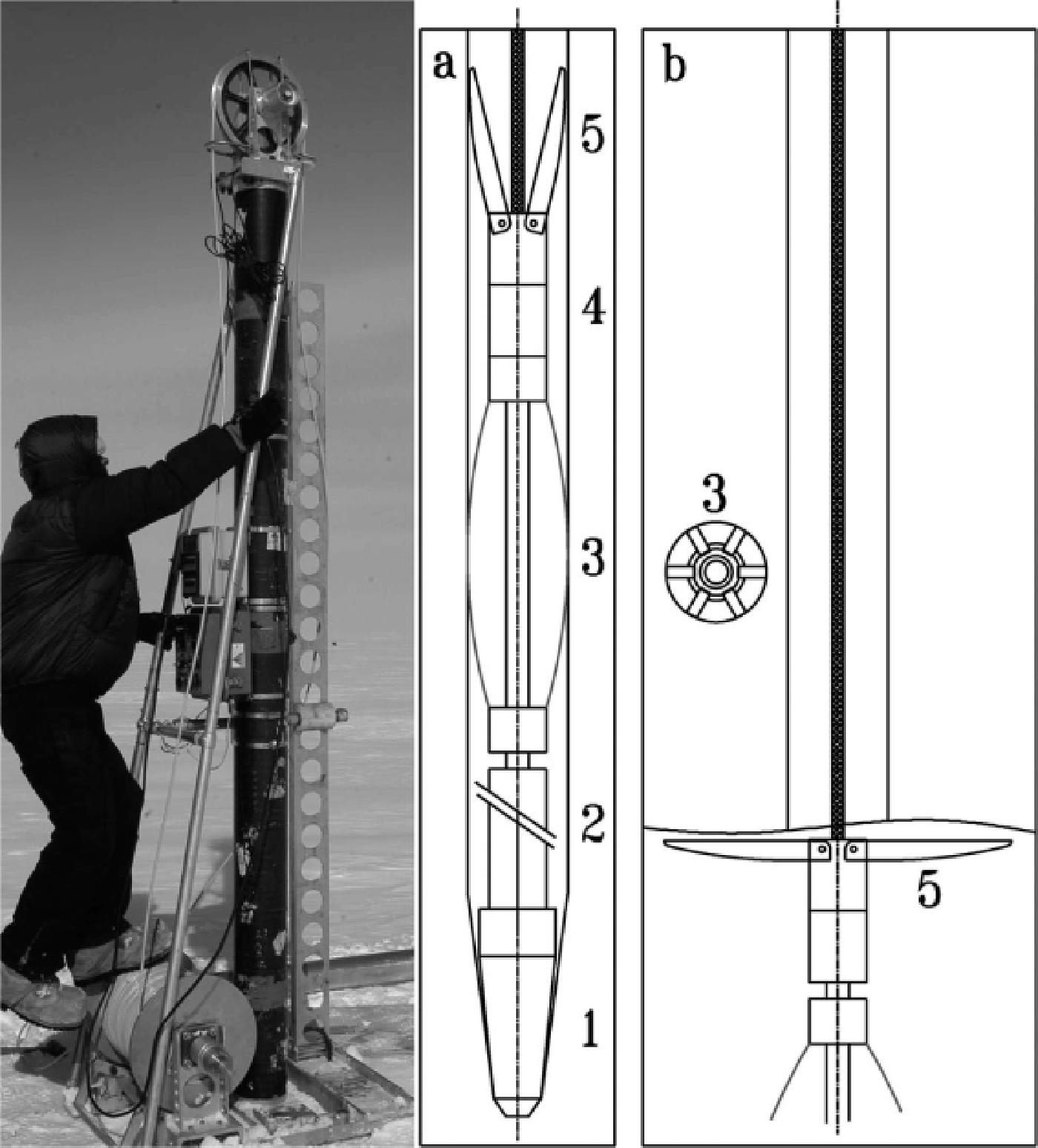
The BPRC EM drill produces ice core of 100–103 mm diameter and a borehole of 129–131 mm diameter. The BPRC drill rig (Fig. 2) with up to 550 m of EM cable is suitable to provide power control (up to 8 kW), has a drill-hoisting system able to pull up the sonde at an average speed of 0.68 m s−1 and includes constant-speed cable (drill) feeding at 0.5–25 mm s−1, drill position digital readout (0–999 m, resolution 0.001 m) and bit pressure monitoring (resolution 0.01 kg).
There are three challenges associated with dry-hole drilling in shelf glaciers: (1) drilling of warm ice at temperatures close to pressure-melting temperature; (2) dry-borehole rheological closure; and (3) sea-water inflow and its freezing in the access borehole after the borehole is connected with a sub-ice-shelf cavity.
The EM drills were developed for dry-hole drilling, and most of them have never been considered for access-borehole drilling in a shelf glacier, with high probability of being submerged in sea water. A few attempts at dry-hole coring of temperate or polythermal glaciers with an EM drill failed at 40–55 m depth because of the presence of warm ice and/or water which compromised the transport of cuttings from the kerf to the storage compartment (Reference Kohshima, Shiraiwa, Godoi, Kubota, Takeuchi and ShinboriKohshima and others, 2002; Reference Neff, Steig, Clark, Connell, Pettit and MenounosNeff and others, 2012; personal communication from M. Gerasimoff, 2004; personal communication from P. Ginot, 2013). Some EM drills were modified for operation submerged in water. The Alfred Wegener Institute EM drill was used on temperate Hofsjökull ice cap, Iceland, where a 100.2 m depth was reached in 9 days (Reference Thorsteinsson, Larsen and WilhelmsThorsteinsson and others, 2003). Low ice-core production rate below 40 m was attributed to short drilling runs. Chip transport was compromised by the presence of water in the borehole, resulting in short penetration per drilling run.
A submersible version of the ECLIPSE drill (Reference Blake, Wake and GerasimoffBlake and others, 1998; Hubbard and others, 2012) was used to make several boreholes in the Roi Baudouin ice shelf (70° S, 24° E). From Hubbard and others (2012) one can assume that at least two boreholes, 15.24 and 66.4 m deep, in firn and glacier ice were made with a modified ECLIPSE drill.
Drilling of both boreholes was terminated and reasons for termination are not reported.
Appreciable progress in core drilling of warm ice has been achieved with the BPRC EM drill equipped with staggered cutters on Quelccaya ice cap, Peru, in 2003 (Reference Zagorodnov, Thompson, Ginot and MikhalenkoZagorodnov and others, 2005). On the temperate Copa-Hualcan glacier, Peru, two dry boreholes reached bedrock at depths of 195 and 185 m (Zagorodnov and Thompson, unpublished information). Staggered cutters produce coarse cuttings that stick less to the coring head and core barrel and enable drilling in warm ice. Borehole rheological closure in temperate ice was noticed but does not complicate the ice coring while drilling at a rate of ~ 4 m h−1 down to 195 m (bedrock). Evidently, slow drilling and pausing of drilling at night extended the time for borehole closure and limited the depth of a dry borehole. A few episodes of freshwater inflow to these boreholes did not present a problem; the BPRC EM drill performed well submerged in fresh water.
Recent Developments: Bprc Hot-Point Drill
The electro-thermal open borehole drills or hot-point drills (HPDs) were developed for fast penetration through temperate glaciers to ~ 200 m depth. Over a dozen HPDs were designed starting in the 1940s (Reference NizeryNizery, 1951; Reference WardWard, 1952; Reference LaChapelleLaChapelle, 1963; Reference Shreve and SharpShreve and Sharp, 1970; Reference Taylor and SplettstoesserTaylor, 1976). Their penetration rate depends on the power and design of the melting tip. In most applications, HPD penetration rate in solid ice is 2–8 m h−1. Only a few HPDs are capable of high penetration rates of 12–25 m h−1 at 1–10 kW power (Reference NizeryNizery, 1951; Reference GilletGillet, 1975; Reference ZagorodnovMorev and others, 1984).
The BPRC HPD, used in the WB 2011 operation, is shown in Figure 2a and b. It has a 40 mm diameter penetration tip, is 1.5 m long and has a penetration rate of up to 11 m h−1. The main difference between the BPRC HPD and other designs is the top anchor mechanism that allows the HPD to be jettisoned below the shelf glacier base after penetration and retrieval of the EM cable to the surface. The jettison feature was designed to reduce the possibility of the drill and cable becoming stuck in the borehole after penetrating into the ocean. The shape of the anchor blades allows the drill to move up and down in the borehole. If the borehole diameter is still large enough to pull the HPD to the surface the anchor will not present an obstacle
Optimization of the new HPD melting-tip design took into consideration high penetration rate at low power, durability at high hydrostatic pressure (>5 MPa) in sea water, the cost of manufacturing, the use of off-the-shelf components and conventional fabrication technologies.
The long cone shape of the melting tip provides better vertical stability during penetration. Durability of the melting tip was improved with a small-diameter (1.58 mm) and long (1575 mm) Watlo coiled cable heater mounted close to the melting surface of the tip in spiral grooves in the copper core (Fig. 2a and b). To insure heat dissipation from the coiled cable heater, it was molded in pure silver. The cable heaters were tested in a pressure chamber at 80 MPa for 96 hours and did not lose their containment. The housing and protective shell of the melting tip is made of stainless steel. Final tests of each of 11 (one lost during silver casting) melting tips included: non-electrified high-pressure test at 5.5 MPa for 2 hours; operation at maximum power in water at 3 kW for 5 min; and 3 hours of operation at 2 kW power. Only five tips passed all three tests.
Access-Borehole Drilling At Windless Bight 2011 Site
The plan for access-borehole drilling through MIS at the WB 2011 site for installation of sensors consisted of two steps: (1) dry borehole drilling with the BPRC EM drill down to a safe depth with minimum risk of the drill being gripped by rheological borehole closure, and (2) penetration through the ice between the dry borehole and the sub-ice-shelf cavity with the HPD. The HPD had to penetrate only a few meters from the bottom of the dry borehole. Two-stage drilling was chosen in order to avoid contact between the EM drill and sea water.
Two access boreholes at the WB 2011 site (BH1 and BH2) were drilled by two-man crews. The sequence of drilling and the DTS cable installation are presented in Table 3. Each of the two boreholes was drilled in 4 days (35 hours total working time) including rig set-up and power system installation, drilling, three relocations and tear-down of the drill set-up. Penetration pitch and opening of anti-torque blades were optimized to achieve maximum production drilling rate. Because the main purpose of the project was to install sensors, the focus was to achieve maximum production drilling rate rather than obtaining good-quality ice core. The optimal penetration pitch on the mechanical drill was found to be 3.6 mm rev−1 while the drill penetration rate was 12 mm s−1, so drilling of a 1 m piece of ice core took ~ 1.5 min. High-penetration drilling pitch (depth of cut per coring-head revolution) produced coarse cuttings that freely moved to the storage compartment and ensured an average 1 m ice-core recovery with every drilling run. The second important innovation that allowed dependable transport of cuttings was lubrication of the core barrel outer surface with propylene glycol (40–50 mL run−1). Lubrication was necessary starting from ~ 60 m depth, otherwise great effort was necessary to pull the core barrel off the drill jacket.
Timing of the WB 2011 access-boreholes drilling and DTS sensors installation

In spite of coarse cutting and high ice-core production rate down to 80 m depth (average ~ 8 h−1), core quality was excellent. Down to 120 m, each drilling run produced two to four pieces of ice core, but below 150 m all core sections consisted of unconsolidated 2–10 mm thick disks only. This was due to increasing bubble pressure within the core ice, resulting in a greater tendency to fracture during drilling.
The speed of lowering of the EM drill by gravity in the WB 2011 boreholes was 1–2.2 m s−1, while average raising speed was 0.68 m s−1. Counting 5 min for drill ‘on-surface’ time, 1.5 min of penetration, 2 min lowering to depth of 190 m and 5.3 min to raise the drill resulted in a total time for the drilling run of 13.8 min. This time translates to an ICPR of 4.3 m h−1. Close to the surface, ICPR was ~ 14 m h−1, close to the maximum documented ICPR of the BPRC EM drill of 15 m h−1. Therefore, average ICPR in the 192 m deep boreholes at the WB 2011 site was ~ 9.2 m h−1 and total dry-hole drilling time was ~ 21 hours.
Borehole BH1 (mooring BH1) at the WB 2011 site was drilled down to 170 m depth. The drilling set-up was then relocated to a new position (40 m north), and the second borehole, BH2 (mooring BH2), was drilled with the EM drill to 185 m. Temperature was then measured in BH1 (170 m depth) and extrapolated to –1.92°C anticipated sea-water temperature at 193 ± 2 m depth. After ice-shelf thickness estimation, the EM drill rig was moved back to the BH1 position. Using the EM drill, BH1 was deepened down to 185.7 m. The HPD was then used to penetrate to the sub-ice-shelf cavity. Immediately after penetration to the sub-ice-shelf cavity (<40 min) the DTS cable was installed. The drilling setup was then moved back to the BH2 position and, using the EM drill, the borehole was deepened to 190.4 m and using the HPD completed to the sub-ice-shelf cavity. The second and third DTS cables were installed in BH2 one after another.
At the moment the HPD pierced through the shelf glacier to the sub-ice-shelf cavity, the bit pressure (cable tension) oscillated for ~ 5 s and then dropped to the weight of the drilling cable. After another 30 s the full weight (HPD and cable) was restored. The HPD acts like a pressure safety valve, blocking–unblocking the orifice into the ocean below. The orifice diameter can then be estimated as 5.6 mm (HPD weight 4 kg and differential pressure between dry borehole and ocean 1.6 MPa). Eventually the orifice enlarged (ice melted) with the water flow to the dry borehole, and water pushed the HPD out of its borehole, observed by decreasing cable tension. It is estimated that boreholes (volume 2.1 m3) were completely filled with sea water in 30 s. The HPD then passed freely to the sub-ice-shelf cavity, and cable tension became slightly smaller than before penetration due to cable and drill buoyancy. The drilling cable was hoisted and it was wet with sea water. Thin (fraction of mm) flat ice crystals up to 8 mm in diameter were attached to the cable surface.
HPD drilling was carried out in BH1 from 185.7 to 192.7 m depth and in BH2 from 190.4 to 192.9 m depth as follows. Previous drilling operations show systematic 0.05 m repeatability of the borehole depth read-out down to 450 m. Thus, the average ice thickness at the WB 2011 site is 192.8 ± 0.025 m, which is 2.8 m higher than the 190 m ice thickness reported by T. Stanton (personal communication, 2010). Most likely the discrepancy in ice thicknesses is related to different positions of the 2009 and 2011 drilling sites.
Vertical stabilization of the EM drill and HPD was achieved by pendulum steering. The drills were partly (80% of weight) hung and their penetration rate was limited by the rate at which the cable was fed. This rate was controlled by the winch motor and is less than the EM drill or HPD penetration rates with full weight of the drill applied to the cutting or melting bit. Vertical stabilization of the HPD was also assisted by the centralizer (Fig. 2), which kept the top of the drill in the center of the borehole. The tip power of the HPD was set at 1.8 kW, and the cable-feeding rate (controlled penetration) of the HPD drilling was set at 2 mm s−1 (7.2 m h−1). This is lower than the HPD penetration rate of 7.6 m h−1 at 1.8 kW. At this rate the HPD produces a borehole 56 mm in diameter.
During the WB 2011 drilling at any depth the drill cable was offset at the surface by <0.05 m from the borehole center. This translates to <7.5 × 10⁻³° borehole inclination. In turn, displacement of the borehole center at the base of the ice shelf with respect to the center at the surface was estimated as <0.26 m.
Windless Bight 2011 Borehole Temperature
The DTS fiber-optic cable provides a unique opportunity for high spatial and temporal resolution measurements of the borehole temperature during freezing and borehole thermal equilibration time. Figures 3 and 4 show BH1 temperatures in a dry hole (170 m; 100 hours after drilling) and during the first 42 hours after drill penetration to the ocean (Reference Tyler, Vaughan, Mantripp and SieversTyler and others, 2013).
Borehole temperature during first 42 hours after filling with sea water: shaded area is permeable firn; box shows the hot-point drilled connecting borehole; lowest solid and dashed lines are dry borehole temperature 4 days after core drilling (before connection to the ocean); first four solid lines from top down represent borehole temperature distribution at 0.5, 2.0, 4.0 and 5.0 hours after filling the borehole with sea water; straight line (10 hours) shows negative temperature gradient; arrows show sea-water/brine level immediately after borehole connection to the sub-ice-shelf cavity (34 m), in following 40 min (37 m) and after borehole closure (40 m).

Borehole temperature record at selected depths (dots are actual measurements); thin solid lines are fifth-power polynomial approximations; thick solid line connects time of brine equilibration.

Thirty minutes after the borehole was filled with sea water it remained practically isothermal from sea-water level (34 m) to the glacier base. In the following 2 hours a few circulation cells arise. These are seen in Figure 3 as semi-sine waves. Over the following 4 hours, almost 30 vertical cells 1–6 m long are formed. These disappeared within 24 hours. A possible mechanism for these brine circulation cells is as follows. High-density brine (–20°C, 1230 kg m–3; Reference Maykut and LightMaykut, and Light, 1995) is formed due to sea water freezing in the cold upper part of the borehole. The high-concentration brine (≤170‰) sinks and is replaced with low-concentration brine. About 10 hours after DTS installation, brine circulation caused the borehole temperature inversion from 40 to 80 m depth (Fig. 3). The thermal anomalies in the circulation cells may also be impacted by regions where the optic fiber was in direct contact with the borehole walls or where local freezing was initiated.
The borehole temperature equilibration takes place in two stages (Fig. 4): (1) freezing of water and release of latent heat and (2) heat dissipation due to heat conduction. When the brine reaches equilibrium concentration, the latent heat is no longer released, but dissipated into surrounding ice.
This moment is seen as the kink between convex and concave parts of the time–temperature relationship in Figure 4. We considered this moment as complete borehole closure (borehole diameter equal to the cable diameter at 37 m depth) due to freezing.
To estimate borehole temperature equilibration time the thermal decay model, often referred to as the ‘hot wire method’, was used (Carslaw and Jaeger, 1959). In this model the freezing water is considered as the linear source of heat in the borehole. The model shows that equilibration within 50 mK of undisturbed ice temperature takes 4 months. Thus, beginning in March 2012 the borehole data below 37 m represent essentially ‘undisturbed’ ice temperature as this is the approximate temperature resolution of the DTS system (Reference Tyler, Vaughan, Mantripp and SieversTyler and others, 2013). Above 37 m depth where the bore-hole remained open, no appreciable changes were noticed, except for seasonal variations in the 0–15 m depth interval.
Analysis Of Windless Bight 2011 Borehole Freezing
Freezing of a borehole filled with fresh and sea water has previously been studied in regard to access-borehole drilling with a hot-water drill in cold ice (Reference TienTien and Yen, 1975; Napoléoni and Clarke, 1978; Reference KociKoci, 1984; Reference Iken, Echelmeyer, Harrison, Rado and BeaudoingIken and others, 1989; Reference Humphrey and EchelmeyerHumphrey and Echelmeyer, 1990; Reference HumphreyHumphrey, 1991; Reference MakinsonMakinson, 1993; Reference Hughes and LanghorneHughes and others, 2013). Here we present field observations and estimates of borehole closure rates obtained with the heat-flux model.
Freezing of the WB 2011 boreholes was studied using the numerical solution suggested by Reference Humphrey and EchelmeyerHumphrey and Echelmeyer (1990). The calculations show (Fig. 5) that the borehole reached the minimal diameter for instrument installation at Windless Bight (25 mm) at 37 m depth (coldest part of the borehole just below sea-water level in BH1) after ~ 6 hours, and at 185 m depth (initial HPD borehole diameter 56 mm) in 1.8 hours. Complete upper borehole (D o = 131 mm) closure at 185 m depths takes ~ 48 hours. In contrast, the portion of the borehole drilled with the HPD at the ice/water interface (193 m) takes ~ 7 hours to close. The DTS cable installed in BH1 was checked periodically by pulling it up every 10–20 min. It was fixed frozen (complete BH1 closure) after 5 ± 0.25 hours at a coldest depth of 37 m.
WB 2011 borehole BH1 diameter evolution during freezing. (a) Dry borehole down to 185 m depth (D 0 is diameter at the beginning of the borehole freezing, t = 0). (b) Borehole drilled with the HPD (depth interval L = 8 m); D = 41 mm at t = 1 hour, solid lines below represent borehole diameter at t = 0.3, 0.6, 1.0, 1.5, 1.8, 2.8 and 3.5 hours; t = 2.83 hours is time when borehole reaches minimal installation diameter of 25 mm.
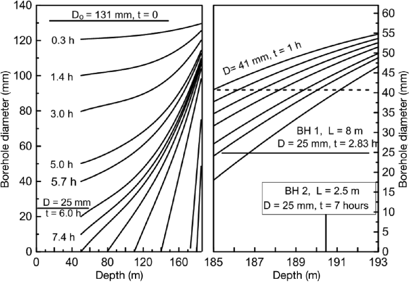
Figure 6 shows complete borehole closure time estimated as brine equilibration time, and numerical model (Reference Maykut and LightMaykut and Light, 1995). The cable freezing time (5.0 ± 0.25 hours) is close to brine equilibration time (5.5 ± 1 hours). The calculated complete freezing time of the borehole filled with fresh water is ~ 25% higher than the brine equilibration time. The difference between freshwater freezing time and brine equilibration time increases with depth and/or ice/brine temperature. It is likely that the discrepancy is caused by ice crystals floating and accumulating in upper parts of the borehole. The discrepancy between experimental freezing rates of the borehole filled with sea water and numerical modeling of borehole freezing with fresh water requires more detailed study. The model also shows that borehole reaming to 0.16 m diameter doubled the time of complete freezing of the borehole and installation of sensors.
Complete borehole closure time: thick solid line approximates calculated (squares) freezing time of the borehole (D o = 131 mm) filled with fresh water (after Reference Humphrey and EchelmeyerHumphrey and Echelmeyer, 1990); dotted line is approximation of brine equilibration time (triangles) as shown in Figure 4; cross is freeze in time of the DTS cable in BH1.

Modifications Of Lightweight Short-Term Open Access-Hole Drilling Technique
Based on the experiences of the 2011 field season, several improvements have been developed. First the efficiency of the access-borehole drilling in shelf glaciers can be raised by increasing the production drilling rate of the EM drill and HPDs. Appreciable increase of the EM drill production drilling rate and respective reduction of the on-site time can be achieved with the following modifications:
-
1. Since transport of cuttings in the BPRC EM drill was excellent, increasing penetration depth per drilling run by lengthening the core barrel by 0.15 m is expected to be successful. This modification will increase the production drilling rate by ~ 15%.
-
2. Drilling with two interchangeable core barrels allowed saving of 2–3 min per drilling run (~100 min/40 runs). This will make it possible to conduct eight additional drilling runs during a working day, or ~ 20% more than drilling with one core barrel.
With these two minor modifications, the total expected increase in production drilling rate of the BPRC EM drill is ~ 37%. Consequently, drilling time (21 hours, WB 2011) could be shortened to 13 hours. Another 4 hours spent on anti-torque and cutter adjustments (Table 3) can be subtracted from the 190 m borehole drilling schedule. Therefore, a 190 m deep dry borehole can be drilled in 21 hours (13 hours drilling and 8 hours set-up/tear-down) and it will be possible to produce a 350 m deep borehole in ~ 48 work hours (one shift d−1 for 5 days). These changes improve efficiency but do not require changes in the surface set-up, and the total weight of the drilling system will be the same.
More substantial modifications of the EM drill system may include more powerful drill and winch motors, a longer drill and core barrel, and a taller hoist mast. These modifications will allow a further 30–40% increase in production drilling rate to average 11.5 m h−1 (200 m deep borehole). The weight of the modified BPRC EM drilling system will increase by ~ 100 kg, and fuel consumption will rise by ~ 25%. Thus, the modified drilling system will allow fast access-borehole drilling (200 m, total time 17–18 hours). The total weight of the modified EM drilling system will be 600 kg. It should be pointed out that drilling at production rates above ~ 10 m h−1 is physically demanding and requires a well-trained drilling team of three persons. It is close to the physical capacities of drill operators during an 8 hour shift.
Lightweight Long-Term Open Access-Borehole Drilling Technique
EM drill and HP access-borehole drilling technique on shelf glaciers has the limitations that (1) the maximum depth of a dry borehole is 300–400 m, and (2) the EM-drill–HP technique is not suitable in shelf glaciers with water-permeable ice at the bottom. The ATED drilling technique is free of these limitations. Use of the combined EM drill and ATED drilling technique shows its efficiency in polar glaciers (Reference Zagorodnov, Thompson, Ginot and MikhalenkoZagorodnov and others, 2005). Using an EM drill for the upper 180 m and ATED down to 460 m (bedrock) depth during Bona–Churchill ice-coring reduced total drilling time by 26% compared to drilling only with ATED. Therefore, a combined system may provide optimal drilling performance. The dry-hole section of an access borehole in a shelf glacier can be 300–400 m deep, and the time reduction could be 70–80%. A hypothetical sequence of a combination method for access-borehole drilling in a shelf glacier is:
-
dry-hole EM drilling down to 300–400 m (38–50 hours at 8 m h−1);
-
partial filling of the borehole with EWS down to 130–150 m below surface (4 hours);
-
ATED drilling down to depth of 5–10 m above the water-permeable ice (2–3 m h−1);
-
filling the borehole with EWS to sea level in the borehole (4 hours);
-
penetration to sub-ice-shelf cavity (2–3 m h−1);
-
correction of level and/or concentration of EWS in the access borehole (4 hours).
Below are conservative estimates of access-borehole drilling time with the EM and ATED technique on the Amery Ice Shelf at the AM04 site (total ice thickness 603 m, water-permeable ice depth 533 m down to the glacier base (Reference Craven, Allison, Fricker and WarnerCraven and others, 2009)). The total access-borehole drilling time is 198 hours, i.e. 20 days (one drilling shift d−1) or 10 days (two drilling shifts d−1), including set-up/tear-down time. An optimistic estimate of through drilling with the EM drill and ATED (drilling rates 10 and 3 m h−1, respectively) is five two-shift drilling days.
The total weight of the EM drill–ATED, comprising drilling equipment (400 kg), ethanol (1800 kg), fuel (700 kg), shelters (500 kg) and power generators (300 kg), is ~ 3800 kg. Thus, the EM drill–ATED drilling equipment weight is ~ 60% of the total weight of hot-water drill equipment. Finally, boreholes drilled using the EM drill and ATED filled with EWS do not require reaming.
Conclusions
Drilling of a small-diameter short-term open access bore-hole in a shelf glacier is possible with EM and HPDs that are 16-fold lighter than a hot-water drill. EM and HPD drilling technique can allow production of a 200–300 m deep access borehole in 4–5 days by a small drilling team.
Combining the EM and ATED drilling techniques makes it possible to produce a long-term (weeks) access borehole of 130 mm diameter in a 500–600 m thick shelf glacier within 5–10 days. This drilling technique requires ~ 4 t of equipment and supplies.
Acknowledgements
We appreciate the efforts and contributions of Herbert Ueda, John Rand, Kendrick Taylor, Andrey Salamatin, Keith Makinson and Dave Pomraning who provided useful information and suggestions on drilling and interpretation of the borehole temperature. Funding for this project has been provided by the Office of Polar Programs of the US National Science Foundation (NSF) under grant ANT1043154, and support was provided to S.T. and D.H. by grants ANT1043395 and ANT1043217, respectively. D.H. acknowledges additional support from ANT-104339 and ANT-073286 Additional instrument support was provided by NSF-CTEMPs under EAR-1128999 and engineering services provided by the UNAVCO Facility with support from the NSF and NASA under NSF Cooperative Agreement No. EAR 0735156.


