


Introduction
Force feedback has been repeatedly proved to greatly improve the quality of a teleoperation scenario, for example, in the case of remote interaction (Yip et al., Reference Yip, Tavakoli and Howe2011). Indeed, beneficial applications of haptic interfaces to teleoperation can be found in several fields, from telesurgery (Guthart and Salisbury, Reference Guthart and Salisbury2000), to space (Imaida et al., Reference Imaida, Yokokohji, Doi, Oda and Yoshikawa2004) and underwater exploration (Khatib et al., Reference Khatib, Yeh, Brantner, Soe, Kim, Ganguly, Stuart, Wang, Cutkosky, Edsinger, Mullins, Barham, Voolstra, Salama, L’Hour and Creuze2016), as well as disaster response (Klamt et al., Reference Klamt, Rodriguez, Baccelliere, Chen, Chiaradia, Cichon, Gabardi, Guria, Holmquist, Kamedula, Karaoguz, Kashiri, Laurenzi, Lenz, Leonardis, Hoffman, Muratore, Pavlichenko, Porcini, Ren, Schilling, Schwarz, Solazzi, Felsberg, Frisoli, Gustmann, Jensfelt, Nordberg, Roßmann, Süss, Tsagarakis and Behnke2019a).
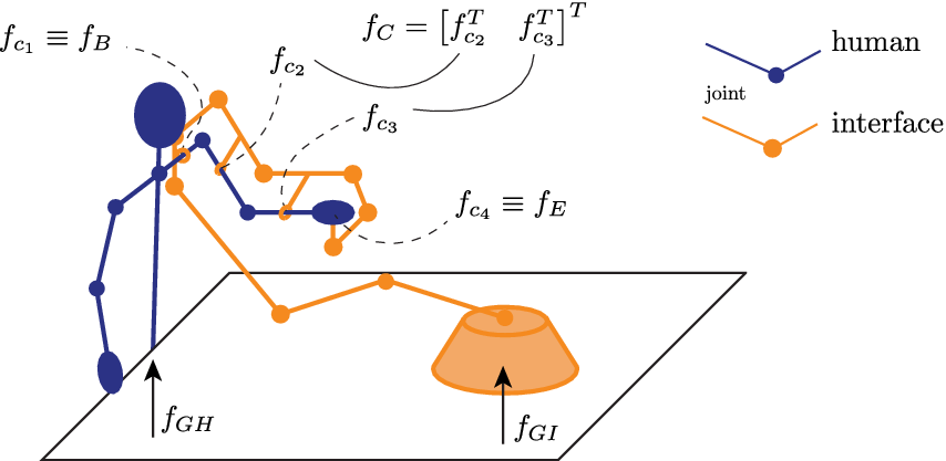
Numerous kinesthetic haptic displays (KHDs) have been proposed to deliver a feedback by acting in the domain of forces and displacements. Usually, these assume that the interaction with the remote environment occurs through one main contact interface, that is, the end effector, which can correspond to the palm/back of the hand or a fingertip of the operator and aim at rendering the wrench corresponding to the total of all the forces and torques exchanged through that contact interface. The way a KHD returns this wrench depends mainly on its kinematics and on its coupling with the operator, and the choice of both these elements can strongly influence the outcome of the teleoperation experience. The motivation behind this aspect can be understood with the help of the general user-interface scheme in Figure 1, where a KHD addressing the whole arm workspace is represented.
Scheme of generalized interaction between operator and kinesthetic haptic display.  $ {f}_{c_i},i=1,\dots, 4 $ are the exchanged forces between the human and the interface at the contact points (assumed to be 4 for simplicity). The force exchanged through the first contact point $ {f}_{c_1} $ is also called $ {f}_B $, whereas the last ( $ {f}_{c_4} $) is called $ {f}_E $. The second and third are then collected in the vector $ {f}_C={\left[{f}_{c_2}^T\;{f}_{c_3}^T\right]}^T $. $ {f}_{GH} $ and $ {f}_{GI} $ denote the contact forces with the ground of the human and the mechanism, respectively.
Traditionally, KHDs were implemented in the form of robotic system with a grounded base (G), to not burden the heavy weight of the system on the operator. With respect to the scheme of Figure 1, G-KHDs always present a ground reaction force  $ {f}_{GI} $. More recently, thanks to the achievements in miniaturization and the use of lightweight materials, engineers started proposing wearable devices (W), that ditch the direct ground connection ( $ {f}_{GI} $ absent) to improve portability of the device and mobility of the user. Please note that the following classification based on the device kinematics and its coupling with the user is just one of the possible topologies. Other classifications can be based, for example, on the used actuation, sensing method, and device control. We will not analyze these last, as they are not the focus of this work and have been already analyzed in existing literature, as Rosen and Ferguson (Reference Rosen and Ferguson2020) and Pacchierotti et al. (Reference Pacchierotti, Sinclair, Solazzi, Frisoli, Hayward and Prattichizzo2017).
The majority of existing systems, both grounded and wearable, are designed as exoskeletons that follow the motion of the operator, link by link, with kinematic joints accommodating for the human articulations. We will refer to these designs as “joint-space” (JS). An important characteristic of JS-KHD is that the kinematics of the human and the device are designed to be, as much as possible, equal. Following this assumption, the torque exerted by each joint of the interface is directly mapped on the corresponding joint of the human, through the various intermediate contact forces (see Figure 1), a hypothesis that heavily simplifies the control of the device. However, the hypothesis of matching kinematics is hardly achievable in reality. Indeed, human joints are not easy to reproduce with a mechanical counterpart. Although they are often approximated with pin joints, their motion is never really purely rotational, nor they are exactly the same across different people. Moreover, their alignment with the KHD joints tend to be always imperfect. Also, a rigid and precise attachment between the two is challenging, due to the compliance of human tissues. As a consequence, undesired relative movements and contact forces outside the image space of the expected wrench can occur. The majority of JS systems live with this problem, accepting the generation of such undesired forces, even if they downgrade the interface performance and the quality of the haptic rendering. Finally, a fundamental limitation of JS-KHD is that they cannot render a desired wrench  $ {W}_d $ exactly, as they only render its projection onto the space of the joint torques, and transfer it to the operator through the actuatable contact forces.
Plenty of examples of grounded, joint-space displays (GJS-KHD) can be found in literature, involving one or more fingers (Agarwal et al., Reference Agarwal, Fox, Yun, O’Malley and Deshpande2015), wrist (Gupta et al. Reference Gupta, O’Malley, Patoglu and Burgar2008; Pehlivan et al. Reference Pehlivan, Lee and O’Malley2012; Martinez et al. Reference Martinez, Ng, Lu, Campagna and Celik2013; Andrikopoulos et al. Reference Andrikopoulos, Nikolakopoulos and Manesis2015; Pezent et al. Reference Pezent, Rose, Deshpande and O’Malley2017; Basteris et al. Reference Basteris, Contu, Plunkett, Kuah, Konczak, Chua and Masia2018; Lee et al. Reference Lee, Song and Yang2018; Pezent et al. Reference Pezent, Fani, Clark, Bianchi and O’Malley2019), and full-arm (Frisoli et al., Reference Frisoli, Rocchi, Marcheschi, Dettori, Salsedo and Bergamasco2005; Gupta and O’Malley, Reference Gupta and O’Malley2006; Mallwitz et al., Reference Mallwitz, Will, Teiwes and Kirchner2015; Barsotti et al., Reference Barsotti, Stroppa, Mastronicola, Marcheschi and Frisoli2018). Several are also the wearable, joint-space solutions (WJS-KHD), in which  $ {f}_{GI} $ is not present, and therefore all the weight of the structure has to be compensated by the user (the interface represented in Figure 1 would start from the contact point corresponding to the force $ {f}_{c_1}\equiv {f}_B $). Nonetheless, wearable devices tend to be lighter than the grounded ones, and, ideally, can be carried and used wherever desired. Similarly to GJS-KHDs, WJS-KHDs can involve different portions of the operator limb. There are some examples of full-arm exoskeletons for teleoperation (Letier et al., Reference Letier, Avraam, Veillerette, Horodinca, De Bartolomei, Schiele and Preumont2008; Schiele and Hirzinger, Reference Schiele and Hirzinger2011; Klamt et al., Reference Klamt, Schwarz, Lenz, Baccelliere, Buongiorno, Cichon, DiGuardo, Droeschel, Gabardi, Kamedula, Kashiri, Laurenzi, Leonardis, Muratore, Pavlichenko, Periyasamy, Rodriguez, Solazzi, Frisoli, Gustmann, Roßmann, Süss, Tsagarakis and Behnke2019b), and some of hand devices as well (Leonardis et al., Reference Leonardis, Barsotti, Loconsole, Solazzi, Troncossi, Mazzotti, Castelli, Procopio, Lamola, Chisari, Bergamasco and Frisoli2015; Gabardi et al., Reference Gabardi, Solazzi, Leonardis and Frisoli2018). On the contrary, there are relatively few wearable JS-KHDs for the wrist and, to the best of the author’s knowledge, almost all of them are designed for application in rehabilitation (Hope and McDaid Reference Hope and McDaid2017; Lambelet et al. Reference Lambelet, Lyu, Woolley, Gassert and Wenderoth2017; Buongiorno et al. Reference Buongiorno, Sotgiu, Leonardis, Marcheschi, Solazzi and Frisoli2018). Note that in both wearable and grounded JS categories, there are several examples of solutions in which particular attention has been put in designing structures that aims to reduce or even remove the macromisalignment issues, as Schiele and Van Der Helm (Reference Schiele and Van Der Helm2006), Sergi et al. (Reference Sergi, Accoto, Tagliamonte, Carpino, Galzerano and Guglielmelli2012), and Jarrassé and Morel (Reference Jarrassé and Morel2011). In Esmaeili et al. (Reference Esmaeili, Guy, Dailey, Burdet and Campolo2013), for example, a wrist exoskeleton with customizable joint parameters has been proposed for such purpose.
An alternative to building an exoskeleton device is that of building a system with one main contact interface with the operator, exchanging forces with them not anymore at the level of joint torques, but at the level of the operational space (OS) devices. Differently from JS, OS interfaces bypass the joint alignment issue, acting directly at the end effector, therefore removing all the intermediate contact points and the associated forces  $ {f}_C $. Furthermore, by avoiding to replicate the human kinematics, this class of devices has the potential to obtain a subspace of actuatable contact forces of full rank and to render an exact and complete wrench at the end effector, without intervening at the joint level. Grounded, operational space (GOS) devices are probably the most popular, and some of them are also available in the market. In this case, $ {f}_B $ is absent (and so the only contact force between human and device is $ {f}_E $ in Figure 1). Examples of small-workspace GOSs are the ones commercialized by Force DimensionFootnote 1 and 3D Systems,Footnote 2 or other platforms developed in research labs, as Frisoli et al. (Reference Frisoli, Sotgiu, Avizzano, Checcacci and Bergamasco2004) and Okamura et al. (Reference Okamura, Richard and Cutkosky2002), as well as the haptic interface of the DaVinci surgical robot from Intuitive.Footnote 3 An example of larger workspace can be found in Hulin et al. (Reference Hulin, Hertkorn, Kremer, Schätzle, Artigas, Sagardia, Zacharias and Preusche2011), where seven DoF robotic arms are used as haptic interfaces. An interesting solution can be found in Oblak et al. (Reference Oblak, Cikajlo and Matjacic2010), which proposes a system that can be configured to work for arm or wrist GOS rehabilitation.
Finally, there is the case of wearable OS devices (WOS-KHD), which try to combine the advantages of GOS-KHD with that of being portable. They present some contact forces at the base  $ {f}_B $, while there are no $ {f}_{GI} $. Consequently, the interface weight compensation is demanded to the user, as for WJS. Furthermore, when rendering a given $ {f}_E $, also a $ {f}_B $ is inevitably generated at the base attachment. Nonetheless, as already said, wearable devices offer the undisputed advantage of portability. In the knowledge of the authors, WOS-KHDs are very few, with only few applications for the hand (Frisoli et al., Reference Frisoli, Simoncini, Bergamasco and Salsedo2007; Fontana et al., Reference Fontana, Dettori, Salsedo and Bergamasco2009; Iqbal et al., Reference Iqbal, Tsagarakis and Caldwell2015; Choi et al., Reference Choi, Hawkes, Christensen, Ploch and Follmer2016; Sarakoglou et al., Reference Sarakoglou, Brygo, Mazzanti, Hernandez, Caldwell and Tsagarakis2016), and none for arm and wrist. Table 1 reports the devices just listed, divided in the categories they belong to.
Classification of existing kinesthetic haptic displays and relative examples.

WOS solutions are less explored due to the difficulties in their design (in particular regarding the stability of their anchors to the user). Nonetheless, they are possibly the most interesting among all systems, because they combine several advantages. Indeed, wearabilty increases portability and facilitates the usage, since WOS-KHDs do not need a particular installation site or support.
Inspired by the advantages just described, this paper explores the possibility to design a new WOS for the wrist to be used in bilateral teleoperation. The idea is to design a light device that embraces the forearm and hand; they can measure the user’s wrist movements without obstructing them, and can render a force at the user palm coherent with the interaction sensed at the remote side. The result is a stand-alone WOS wrist KHD named “Wearable Delta” (W $ \Delta $), shown in Figure 2. The device is anchored onto the forearm and uses a hybrid parallel–serial kinematic structure to render forces at the user’s hand, avoiding the problem of wrist axis joint misalignment. It also integrates a sensorized elbow brace and an inertial measurement unit (IMU) that, combined with the position sensors of the mechanism, can be used to calculate the user’s arm pose and their hand trajectory, which can in turn be used as input to the remote platform.
Picture of the W $ \Delta $ worn, complete with sensorized elbow brace and Myo armband for the arm trajectory tracking: (a) front and (b) back views.

The paper is structured as follows: Section “Concept” introduced the concept of the W $ \Delta $ and briefly summarizes its forward kinematics, exhaustively analyzed in Appendix A. The design specifications and implementation follow in Section “Design.” Section “Characterization” reports the mechanical characterization of the W $ \Delta $, and Section “Psychophysical Assessment” describes a performed psychometric assessment. Section “Teleoperation Framework” quickly summarizes the implemented bilateral teleoperation scheme (its complete analysis is reported in Appendix B), divided in the delivery of haptic feedback and the control of a remote robotic arm. Section “Experimental Validation” reports two example tasks to show general functionality, whereas Section “Usability Assessment” reports a preliminary usability assessment of the device and Section “Discussion, Limitations, and Future Developments” discusses the results and possible future improvements. Finally, in Section “Conclusion,” we conclude this manuscript with a critical summary of results and a description of future work.
Concept
The idea proposed in this work is to design a WOS-KHD attached to the forearm that acts directly on the palm for bilateral teleoperation applications. The wearable design is chosen to improve its portability, and the involvement of the final portion of the user arm only limits the device total weight and size. The choice of the OS option, instead, is motivated to improve the rendering precision of the desired wrench directly to its application point, in order to augment the haptic sensation and to make it as close as possible to the remote interaction. To avoid any possible kinematic mismatch issues, the device has six DoFs, since a frame fixed in the palm center performs both rotations and translations with respect to the forearm. The choice of the kinematic structure considers also user’s comfort. In particular, the chosen kinematics influence the weight distribution on the arm, and consequently the effort required for its compensation. A structure with a good weight distribution is preferable, for example, minimizing the distance of its center of mass with respect to the forearm longitudinal axis. Symmetric parallel kinematic chains can help matching this requirement. Some of the wrist devices listed in Section “Introduction” already implement parallel structures, from which take inspiration, as Andrikopoulos et al. (Reference Andrikopoulos, Nikolakopoulos and Manesis2015) and Lee et al. (Reference Lee, Song and Yang2018). The most interesting, and the one from which our device takes partial inspiration, is the RiceWrist. Presented in Gupta et al. (Reference Gupta, O’Malley, Patoglu and Burgar2008) and Gupta and O’Malley (Reference Gupta and O’Malley2006), it is a GJS rehabilitation device with four DoFs which uses a specific parallel mechanism, introduced in Lee and Shah (Reference Lee and Shah1988), with two rotational DOFs and one translational DoF. The design specifications of the RiceWrist, which is intended for rehabilitation, are such that the DoF arrangement and kinematics are thought to precisely guide the patient movements during the rehabilitation process. Nonetheless, a solution that foresees the explicit application of forces in function of trajectory errors and assistance-needed parameters has been proposed in Pehlivan et al. (Reference Pehlivan, Sergi and O’Malley2014). This indicates that haptics and rehabilitation devices can converge to similar control solutions, and mainly differ in the intended application and consequent design specifications. On this aspect, our wrist KHD is not conceived and designed to perform movement guidance, but rather to exert desired forces (coherent with a remote interaction) while allowing unconstrained user wrist motion and offering complete wearability.
The solution we propose is a structure resulting from the combination of both parallel and serial chains. It consists in the serial assembly of two quite common structures (see Figure 3a): a Delta robot structure (Clavel, Reference Clavel and Burckhardt1988) and a three-DoF gimbal. As shown in Figure 3a, the base of the Delta is conceived as a ring to fit the upper part of the forearm, with the actuators distributed around it. Ideally, when the hand is aligned with the forearm, the moving plate center coincides with the hand palm center. The Delta structure has three DoFs, all linear. Consequently, without additional joints, the palm’s rotations would be blocked, and so any wrist movement. The addition of a gimbal structure on the Delta’s plate (brown in Figure 3a) provides for the three missing rotational DoFs. The moving plate is reduced to just a ring used to connect each of the three legs universal joints to the external arc of the gimbal. The gimbal, then, uses the ring as a base, with its axes passing through the palm’s center. Its last link is fixed on the user’s backhand. Providing actuated joints also for the gimbal would mean adding more weight at the user’s arm tip, and a less compact solution, due to the space required by the actuators. Therefore, the idea is to leave the gimbal passive and to rely only on the Delta actuation, which will be controlled in torques for the haptic feedback. It follows that the device is able to provide linear forces only at the backhand anchor point. Please note that, with this kinematics, the device will automatically adapt to the user’s arm lengths. Indeed, while the gimbal enables the wrist rotation, the Delta structure automatically adapts to the user arm (especially along the forearm axis), as it opposes resistance to hand movements only when a force actuation is commanded. Furthermore, since the W $ \Delta $ totally envelopes the user’s forearm and hand, its kinematics can be used to reconstruct the pose and velocities of the user’s arm. The study of the device kinematics and its integration with the humans is explained in detail in Appendix A. For the sake of brevity, we report here the final results. The forward kinematics of the user arm which exploits the W $ \Delta $ kinematics can be written as follows:
 $$ {H}_{pm}^0\left({q}_{\overline{H}}\right)={H}_{sh}^0\left({q}_{sh}\right){H}_{el}^{sh}\left({q}_{el}\right){H}_{b_{\Delta}}^{el}{H}_{pm}^{b_{\Delta}}\left({q}_{W\Delta}\right), $$
with  $ {H}_{pm}^0 $ being the homogeneous transformation matrix of the palm frame $ {\Psi}_{pm} $ with respect to word fixed frame $ {\Psi}_0 $.
Technical drawings and information of the W $ \Delta $: (a) real device aspect with its different functional components highlighted; (b) tech drawings of the three main parts with highlighted lengths defined in the device; and (c) table summarizing the chosen values of the different dimensions interested in the design.

Similarly, the system Jacobian, which allows to express the user palm twist as function of the arm and device joint velocities, is
 $$ {T}_{pm}^{pm,0}={J_{\overline{H}}^{pm}}_{\left(6\times 10\right)}{\dot{q}}_{\overline{H}}=\left[{J_{H_{el}^0}^{pm}}_{\left(6\times 4\right)}\hskip0.5em {J_{W\Delta}^{pm}}_{\left(6\times 6\right)}\right]\left[\begin{array}{c}{\dot{q}}_{sh}\\ {}{\dot{q}}_{el}\\ {}{\dot{q}}_{W\Delta}\end{array}\right]. $$
 For a detailed explanation of these formulas, please refer to Appendix A. In the next section, the design of the W $ \Delta $ is reported.
Design
This section presents the hardware design of the W $ \Delta $. First, the description of the mechanical requirements and their accomplishment will be explained, followed by the description of the electronics, sensors, and actuators.
Mechanical Design
The technical drawing of the realized device are depicted in Figure 3. Since the W $ \Delta $ has to be worn and attached to the forearm, the base of the Delta structure is designed as a ring (see Figure 3a,b). Referring to Figure 3a, the Delta base holds the actuators (cases in red) and the electronics (cases in dark gray). The forearm anchor is created linking the Delta base to an elbow brace (see Figures 2 and 3a for the elbow brace flange, depicted in dark green). The reason of this is to overcome to the stretch and slip of the skin. Embracing both arm and forearm and providing a rigid plate, the brace helps the W $ \Delta $ to maintain a stable position despite the arm movements. The elbow encoder support (light green in Figure 3a) is attached to the brace flange. All these components are 3D printed in acrylonitrile butadiene styrene (ABS).
The kinematics of each leg of the Delta is R–U–U. It has been realized with the rotational joint centered at the output shaft of each actuators, while an equivalent solution to the two universal joint has been created combining two rotational joints parallel to the actuator one and a four-bar mechanism with its joint axes normal to the previous (Figure 3). All the parts of the legs, in yellow in Figure 3a, are realized in stainless steel, whereas the joins (light blue) are in aluminum.
The moving plate of the Delta, that also works as base for the gimbal, is designed as a ring as well. It is supported by the last joints of the Delta legs, and in turn it houses the first joints of the gimbal, which is simply realized as a layering of rotating arcs. The most internal arc is designed to match with the hand support made for the commercial GoProFootnote 4 action camera called The Strap, Footnote 5 to which the user’s backhand is anchored. In this way, the user does not have to grasp any handle, as the interface is fixed at the back of its hand through straps (see the video linked in the footnote to easily understand the Strap functioning). The moving plate and the gimbal arcs (brown in Figure 3a) are 3D printed in ABS, while the gimbal passive joints (light blue) are realized in aluminum and house the gimbal encoders.
Actuators and Electronics
The motors used to actuate the three base joints of the Delta structures are Maxon Motor DCX 22 S + GPX22 12 Volt (83:1). This combination allows a maximum output continue torque of 1.2118 Nm at 1.65 A, and a peak torque of 8.964 Nm at 11.8 A. The chosen motor and gearbox have the efficiency of 85.2 and 74%, respectively, which is traduced in a very good backdrivability. This aspect is very important in a teleoperation scenarios, as the device should be as transparent as possible. To measure the rotation of the different joint axes, we use Austrian Microsystems 5054 position sensors, with a 16-bit resolution, corresponding to a resolution of  $ \sim 0.011{}^{\circ} $ ( $ =\sim 2\times {10}^{-4} $ rad). A total of seven encoders is present: three placed coaxially to the output motor shafts, three in the gimbals, and one aligned with the rotational axis of the elbow brace (see Figures 2 and 3a). As a consequence, the measurement resolution of the gimbal axis position (wrist rotation) is the same of the used encoders. The Delta plate position measurement resolution, instead, is not constant, as it depends on the Delta Jacobian (see (17)), and therefore on its dimensioning (explained hereafter) as well as its instantaneous joint position. Moreover, it also varies depending on the movement direction. Just to give an idea, considering the link length resulting from the following dimensioning, a standard user 1.8-m tall, and a straight wrist position ( $ {R}_{pm}^{b_{\Delta}}=I $ and $ {p}_{p_{\Delta}}^{b_{\Delta}}=\left[\mathrm{0,0,0.2508}\right] $ m), we have a movement resolution of $ \sim 0.3 $ mm along $ x $, $ \sim 0.12 $ mm along $ y $, and $ \sim 0.05 $ mm along $ z $. Given the upper-arm length $ {l}_u $ (Figure 17b), the elbow encoder is used to calculate the matrix $ {H}_{el}^{sh} $ (see (21) in Section “Human Arm Kinematics” in Appendix A). The electronic boards used to read the encoders and control the motors are the ones presented in Della Santina et al. (Reference Della Santina, Piazza, Gasparri, Bonilla, Catalano, Grioli, Garabini and Bicchi2017).
At the upper arm, a Myo armband is worn (see Figure 2). In the Myo armband, an IMU is used to extrapolate the rotation matrix of the homogeneous transformation matrix  $ {H}_{sh}^0 $ (see Section “Human Arm Kinematics” in Appendix A). Moreover, the user holds a small trigger, embedding an eighth encoder, which can be used to control the end effector of the slave, for example, opening and closing a gripper.
Device Dimensioning and Anthropomorphic Matching
The first general requirement for the W $ \Delta $ is to be able to fit different arm sizes. From Winter (Reference Winter2009), the forearm length (from elbow to wrist) of an adult is the 14.5% of its height, while the hand length (from wrist to fingertips) is the 10.8%. These estimates are valid for both males and females. Then, covering users with height ranging $ h=\left[\mathrm{1.6,2}\right] $ m, and adjusting the rounding up so to match also outliers, the forearm length ranges can be set to $ {l}_f=\left[\mathrm{0.23,0.32}\right] $ m. The range distance between the wrist’s and the palm’s center (calculated as a third of wrist–fingertips length) can be set to $ {l}_h=\left[\mathrm{0.06,0.08}\right] $ m. The workspace the device has to cover can be defined by combining the lengths $ {l}_f $ and $ {l}_h $ and the range of motion shown in Table 2. It has to be considered also that the Delta base will be anchored on the forearm at a distance of $ \sim 0.05 $ m from the elbow. Finally, the desired workspace can be rounded up joining all the upper half sphere centered in $ z={l}_f-0.05 $ m with a radius $ \rho ={l}_h $, with $ {l}_f=0.145h $ and $ {l}_h=\frac{0.108}{3}h $.
Range of motion (ROM) of human (a) forearm supination/pronation, (b) wrist abduction/adduction, and (c) wrist flexion/extension and length ranges of (d) forearm and (e) hand (wrist–palm’s center) human segments

All the lengths chosen in the design analysis that will follow are summarized in Figure 3c. The Delta structure parameters are basically four (see Figure 17a): (i) the radius of the base  $ {r}_{b_{\Delta}} $; (ii) the radius of the moving plate $ {r}_{p_{\Delta}} $; (iii) the length $ {L}_{\Delta} $ of the driver leg; and (iv) the length $ {l}_{\Delta} $ of the driven leg.
The two radii are chosen in order to fit all the arm sizes. In particular,  $ {r}_{b_{\Delta}} $ is influenced by the internal radius of the base circle $ {r}_{b_{\Delta},\mathit{\operatorname{int}}} $ (see the third drawing of Figure 3b), that should be large enough to fit any forearm. It has been set $ {r}_{b,\mathit{\operatorname{int}}}=0.07 $ m and, as consequence, $ {r}_{b_{\Delta}}=0.0975 $ m.
On the other side, the gimbal has to be large enough to not interfere with the user’s wrist in all its movement. Considering this, the various radii of the gimbal have been set as (see top drawing of Figure 3b):  $ {r}_{g,\mathit{\operatorname{ext}}}=0.1105 $ m, $ {r}_{g, mid}=0.09 $ m, and $ {r}_{g,\mathit{\operatorname{int}}}=0.075 $ m. In this way, the hand should never touch the structure.
Desiring a compact and easily foldable solution, we would like to have  $ {r}_{p_{\Delta}}+{l}_{\Delta}={r}_{b_{\Delta}}+{L}_{\Delta} $, and in particular $ {r}_{p_{\Delta}}={r}_{b_{\Delta}} $ and $ {l}_{\Delta}={L}_{\Delta} $. The first condition ( $ {r}_{p_{\Delta}}={r}_{b_{\Delta}} $) is achieved by shifting the plane in which the plate joint legs lie below the gimbal structure (an area never occupied by the user’s limb), with an offset of $ {z}_{p, off}=0.025 $ m (see the gimbal drawing of Figure 3b).
Once  $ {r}_{b_{\Delta}} $ and $ {r}_{p_{\Delta}} $ have been defined, we would like to define the lengths $ {L}_{\Delta} $ and $ {l}_{\Delta} $ that (i) cover the desired workspace (the one spanned by the user palm center) in the one of W $ \Delta $ and (ii) assure the rendering of a continuous force of at least 5 N in any direction in any point of the desired workspace, considering a maximum continue current of 1.5 A (slightly lower than the one provided by data sheet in order to be sure to prevent motors’ damage). The possible combinations of $ {l}_{\Delta} $ and $ {L}_{\Delta} $ are explored through a recursive algorithm, which uses the inverse kinematic algorithm proposed in Williams (Reference Williams2016), considers also the offset $ {z}_{p, off} $, and varies the lengths $ {L}_{\Delta} $ and $ {l}_{\Delta} $ with steps of 0.01 m. Finally, we choose a combination of $ {L}_{\Delta} $ and $ {l}_{\Delta} $ that respect the second condition $ {l}_{\Delta}={L}_{\Delta} $, minimizing these two lengths: $ {L}_{\Delta}={l}_{\Delta}=0.16 $ m. This choice reduces the envelope of the device as much as possible and, together with $ {r}_{p_{\Delta}}={r}_{b_{\Delta}} $, also the complete fold and compactness of the interface when not used. The width of the four-bar is set as $ {l}_{fb}=4.5 cm $. Table 3c summarizes all the values chosen for the different length of the W $ \Delta $, whereas Table 4 summarizes the currents’ and motors’ torques from data sheet, as well as the corresponding assured force at $ {\Psi}_{p_{\Delta}} $ and the torque at the user wrist in the nominal case $ {l}_h=0.7m $. Last column, instead, show the various data considering as maximum current the used value of 1.5 A, as explained just above.
Device torques and forces summary. Columns divided in: (a) maximum continuous and (b) peak values (both from data sheet), and (c) used ones (through software saturation)

a This is the maximum force assured in all the interested workspace given the current saturation at 1.5 A, as specified in Section “Device Dimensioning and Anthropomorphic Matching.” This means that, depending on the device Jacobian (and thus on its joint position), it is also possible to reach greater values.
The custom 7-point Likert scale questionnaire for the comparison of the two leader interfaces

The W $ \Delta $ itself has a weight of 1.775 Kg, which grows to 2.224 Kg when considering the elbow brace (0.356 Kg) and the Myo armband (93 g). Figure 2 shows the actual final result mounted on a user’s arm.
Characterization
A characterization of the device was performed, in order to match the actual force applied at the end effector with the desired one. The setup used for the W $ \Delta $ characterization is depicted in Figure 4. The passive gimbal is unmounted from the W $ \Delta $, consequently leaving only the Delta part, and replaced with a structure that functions as a flange between the Delta and the tool side of an ATI mini45-e F/T sensor.Footnote 6 The sensor is fixed to the end effector of a Panda robotic arm (Franka EmikaFootnote 7). The orientation of the Panda end effector is fixed so to be normal to the Delta base for the whole characterization. Its position is instead regulated so to match the desired position of the Delta moving plate center.
Setup used for the characterization: the Delta has the base anchored to the table, and the plate attached to the Franka robot end effector through the ATI mini45-e F/T sensor. The Franka end-effector rotation is blocked so to be always look perpendicular to the table plane, while it is moved to pose the Delta plate in the interested position.

The characterization is performed as follows: 38 points lying on the edge and inside the expected users’ workspace are chosen. In each point, 144 directions on a unitary sphere are defined. All these directions define the versors  $ {\hat{f}}_d\in {\mathrm{\mathbb{R}}}^3 $ of the desired forces. For each direction, a force is applied with intensity $ \left\Vert {f}_d\right\Vert $ going from 0 to 5 N and then back to 0 again, with steps of 1 N applied for 1.5 s. The resulting force is then
 $$ {f}_d={\hat{f}}_d\left\Vert {f}_d\right\Vert . $$
 Through the Delta Jacobian  $ {J}_{\Delta}\left({\theta}_{\Delta}\right) $ of (17), the desired torques $ {\tau}_{\Delta, d} $ are calculated as
 $$ {\tau}_{\Delta, d}={J}_{\Delta}{\left({\theta}_{\Delta}\right)}^T{f}_d, $$
and the commanded currents to the motors  $ {I}_c $ are calculated as
 $$ {I}_{\Delta, c}={C}_{T_m, ds}{\tau}_{\Delta, d}, $$
being  $ {C}_{T_m, ds} $ the current–torque actuator constant provided by the data sheet. For all the 38 chosen points, the commanded currents $ {I}_{\Delta, c} $ to the motors, the motors’ positions $ {\theta}_{\Delta} $, and the force measured by the F/T sensor $ {f}_m $ are registered and averaged in the time window of the application of all the desired forces. The average measured force $ {\overline{f}}_m $ is then converted in measured torques $ {\tau}_{\Delta, m} $ through the Delta Jacobian:
 $$ {\tau}_{\Delta, m}={J}_{\Delta}{\left({\theta}_{\Delta}\right)}^T{\overline{f}}_m. $$
 Figure 5a–c shows the 3D plots of  $ {\theta}_{\Delta}-{\tau}_{\Delta}-{I}_{\Delta} $. Projected on the $ {\tau}_{\Delta}-{I}_{\Delta} $ plane, the three characteristics can be well approximated by a straight line. The resulting $ {\tau}_{\Delta}-{I}_{\Delta} $ relations for each motor are then approximated as
 $$ {I}_{\Delta_1}=1.308{\tau}_{\Delta_1}+0.009552;\hskip1.5em {I}_{\Delta_2}=1.462{\tau}_{\Delta_2}-0.002873;\hskip1.5em {I}_{\Delta_3}=1.436{\tau}_{\Delta_3}-0.001714. $$
 Furthermore, we performed a step response analysis. Figure 6 shows the results of the actuators response to a torque step  $ {\tau}_s=1 $ N, with a control loop frequency of 400 Hz (cycle time $ 2.5 $ ms). $ {T}_n $ indicates the time required by the actuators to reach the $ n\% $ of the step. The times reported in the figure are the slowest between all the motors. The Rise Time $ {T}_r $, defined as the time required by the response to rise from 10 to 90% of its final value ( $ {T}_r={T}_{90}-{T}_{10} $), is $ {T}_r=0.0614 $ s. Furthermore, $ {T}_s $ is the Settling Time and corresponds to $ {T}_{95} $ and results $ {T}_s=0.0728 $ s. Considering the system of first order, we can then find the control loop bandwidth $ {\omega}_H $ as
 $$ {\omega}_H=\frac{3}{T_s}=41.2088\frac{\mathrm{rad}}{\mathrm{s}}. $$
Results of the three motors’ characterization ([a] first, [b] second, and [c] third motors): position (rad)–torque (Nm)–current (A) fitting (brown points and colored surfaces), relative torque (Nm)–current (A) projection (gray points), and resulting first-order polynomial fitting (blue line) with relative equation.

Step response of the W $ \Delta $ with reference torque $ {\tau}_s=1 $ N. $ {T}_n $ indicates the time required by the actuators to reach the $ n\% $ of the step. The times reported are the slowest between all the motors. $ {T}_s $ is the Settling Time and corresponds to $ {T}_{95} $. $ {T}_r $ is the Rise Time, defined as $ {T}_r={T}_{90}-{T}_{10} $.

Psychophysical Assessment
By means of psychophysical experiments, we evaluate the capacity of human participants in discriminating the different force intensity rendered by the device in different direction.
Materials
The setup used for this experiments is shown in Figure 7. The W $ \Delta $ is anchored to a structure that holds it and is fixed to a table. The subjects wear the W $ \Delta $, while sitting in a comfortable position, and try to maintain the straight position of Figure 7 for the whole experiment duration. Furthermore, the subjects are blindfolded and provided with an external white noise by noise-canceling over-ear headphones. The pool of subjects is composed of six participants, three males, and three females, between 25 and 35 years old.
Setup used for the W $ \Delta $ psychophysical test: the subject, seated, leans its elbow on a comfort foam and wears the W $ \Delta $, and witch is supported by a custom frame. The drawn reference frame orientation corresponds to the one of the base of the W $ \Delta $ (see Figure 17a) in order to facilitate the read of plots reporting the assessment results in Figure 8.

Methods
The assessment method is divided in three subexperiments, each of them concerning one direction, according to the frame of Figure 7. We used the method of constant stimuli (Gescheider, Reference Gescheider1976): in a forced-choice task, we presented participants with two stimuli of different intensity and asked them to report which of the two was perceived as stronger. After preliminary tests, the range of the stimuli has been set  $ \left[2,4\right] $ N. Then, the Compared Stimuli (CS) are 2, 2.33, 2.67, 3, 3.33, 3.67, and 4 N, while the Reference Stimulus (RS) is 3 N, with a step of 0.33 N. The corresponding torques at the wrist for these CS are in the range $ \left[\mathrm{0.12,0.24}\right] $ Nm in case of minimum $ {l}_h $ (0.06 m), and in the range $ \left[\mathrm{0.16,0.32}\right] $ Nm in case of maximum $ {l}_h $ (0.08 m, see Table 2). Twenty repetitions of each RS–CS couple are rendered to each subject, half with the RS as first stimulus and the other half with RS as second stimulus, all in a randomized order. Each stimulus is rendered as follows: a ramp of 0.5 s increases the applied force from 0 N to the desired stimulus to avoid discontinuities, then the force is kept constantly equal to the desired stimulus for 1.5 s and finally decreased back to 0 N with another ramp of 0.5 s. Between the first and second stimuli of each pair, a pause of 1 s is used. For each direction, then, the total number of trials is 140, presented in a pseudorandom order. The seed for the pseudorandom algorithm is changed for each new subexperiment. The order of the three subexperiments (three different directions of the applied forces) is shuffled with the same method. Once the desired force is given, the corresponding motor torques are calculated through (4), and the commanded currents through (7). Participants’ answers were recorded and saved for analysis.
Data Analysis
The data resulting from the experiment of each subject, as well as the total pool, are reported in Figure 8. Abscissa axes’ values correspond to the CS used in the experiment, whereas ordinate axes’ values correspond to the portion of answers in which the subject felt the CS greater than the RS. Colored dots indicate the result for each CS in the three directions. It follows that, in the ideal case, these dots should correspond to 0 if the CS is lower than RS, 0.5 if the CS corresponds to the RS, and 1 if the CS is greater than the RS.
Results of the force discrimination in the different directions for each subject (first 12 boxes) and for the total data pool (bottom big box). Abscissa axes are centered at the RS (RS = 3 N), with range corresponding to the one of the CS (CS $ \in \left[2,4\right] $ N). Grid vertical lines—plots left and right borders included—indicate the seven used CS (see Section “Methods”). On the ordinate axes, “Portion of greater” for each CS is reported, which is the portion of trials for that specific CS in which the subject declared it greater than the RS. Each box shows results for each CS (dots) and binomial fit (curve; see Section “Data Analysis”) in each direction (red for $ x $, yellow for $ y $, and blue for $ z $; see Figures 7 and 17a). The total plot also reports point of subjective equality (PSE) and just noticeable difference (JND) for each direction.

By means of a generalized linear model, the human testers’ sensitivity is tested in all the principal directions. The fitting is performed assuming a binomial distribution. After the fitting, the PSE and the JND are calculated for each direction and subject, as well as for the whole pool of recorded data. The resulting fitting curves, PSE and JND values for each subject and for the total pool, are reported in Figure 8.
The Weber constant resulting from the characterization (JND/RS  $ =\sim 10\% $) is quite close to the intervals found in Pang et al. (Reference Pang, Tan and Durlach1991) and Jones (Reference Jones1989) (c.a. $ \left[5-10\right]\% $), confirming that the W $ \Delta $ does not alter the capacity of the user to discriminate forces. Furthermore, the average JND along the different direction is 0.338 N and exactly corresponds to the wrist average force control resolution calculated in Tan et al. (Reference Tan, Srinivasan, Eberman and Cheng1994). This means that the device potentially allows the user to control a remote/virtual force through the device with the same accuracy they would have during a real physical interaction.
Teleoperation Framework
In this work, we implemented a classic position-force architecture (Hannaford and Ryu, Reference Hannaford and Ryu2002). The follower robot is moved through an impedance control, that takes as reference the user’s hand position/twist. The interaction wrench sensed at the remote side is fed back to the user through the interface. A representation of the whole scheme is shown in Figure 9. Its details are expansively explained in Appendix B, together with the study and characterization of the haptic feedback (Section “Haptic Feedback” in Appendix B). For the sake of brevity, we here report only the final and essential results. At the leader side, the wrench applied by the W $ \Delta $ to users palm $ {W}_a^{pm} $ corresponds to
 $$ {\displaystyle \begin{array}{l}{W}_a^{pm}(t)={C}_{W\Delta}(t){W}_d^{pm}(t)={C}_{W\Delta}(t){W}_e^{ee}(t)\end{array}}, $$
where  $ {W}_d^{pm} $ is the desired wrench at the palm, corresponding to the environment wrench sensed at the follower end effector $ {W}_e^{ee} $. $ {C}_{W\Delta} $ is the map from the desired to the applied Wrench, which is the function of the device actuation and kinematics. Please refer to Section “Haptic Feedback” in Appendix B for its complete derivation. The follower, instead, is controlled in impedance, as said before. The total commanded Wrench $ {W}_{f, tot}^{ee} $ expressed in the end-effector frame $ {\Psi}_{ee} $ is
 $$ {W}_{f, tot}^{ee}(t)={W}_{f, cmd}^{ee}(t)+{W}_{f, cmp}^{ee}(t)={\Sigma}_c\left({T}_{pm}^{pm,0}(t),{T}_{ee}^{ee,0}(t)\right)+{\hat{\Sigma}}_f\left({T}_{ee}^{ee,0}\right) $$
which is the sum of the impedance control Wrench  $ {W}_{f, cmd}^{ee} $ and the equivalent gravity compensation Wrench $ {W}_{f, cmp}^{ee} $. $ {T}_i^{k,j} $ indicates the twist of the frame $ {\Psi}_i $ with respect to $ {\Psi}_j $ expressed in the frame $ {\Psi}_k $.
Teleoperation control loop block representation. Apices indicating the reference frame in which the entities are expressed and not reported for the sake of readability.

At the left side, the user/leader-side scheme is depicted.  $ {Z}_{\ast } $ are impedances in the JS. Block $ {C}_{W\Delta} $ corresponds to (9), while $ {J}_{wr} $ is the wrist Jacobian, which is associated to $ {H}_{pm}^{wr} $ of (21) and is used to map the torques at the wrist joint $ {\tau}_{wr} $ in the wrench $ {W}_{wr} $ in the frame $ {\Psi}_{pm}\equiv {\Psi}_{p_{\Delta}} $.
At the right side, the remote/follower-side block representation is shown.  $ {\Sigma}_{\ast } $ are impedances in the Cartesian. The sum of contributions from blocks $ {\Sigma}_c $ (impedance controller) and $ {\hat{\Sigma}}_f $ (dynamic compensation) correspond to the total commanded wrench $ {W}_{f, tot} $ of (10). This and the environment interaction force $ {W}_e $ influence the follower dynamics $ {\Sigma}_f $, here indicated with its inverse due to causality consistency.
Experimental Validation
This section reports some simple experiments to validate the device used in the teleoperation framework described in the previous section. First, the experimental setup is introduced, both for the leader side and the follower side (Section “Validation Setup”). Section “Examples of Use” reports the examples of usage of the W $ \Delta $ in free-space position and simple interaction and analyzes the results.
Validation Setup
The leader–follower framework used for the experimental campaign is shown in Figure 10. The follower is a Panda robotic arm by Franka Emika,Footnote 8 the same used for the W $ \Delta $ characterization (Section “Characterization”). The used follower end effector is the anthropomorphic Pisa/IIT SoftHand (Catalano et al., Reference Catalano, Grioli, Farnioli, Serio, Piazza and Bicchi2014).
Setup used for the W $ \Delta $ experimental validation.

The follower end-effector transformation matrix  $ {H}_{ee}^0 $ and twist $ {T}_{ee}^{ee,0} $ are provided by the software library interface of the robot (Franka Control Interface), as well as its Jacobian $ {J}_s^{ee} $ and external interaction wrench $ {W}_{ext}^{ee} $, used to provide the feedback to the user and to evaluate the subjects performances, as it will be explained hereafter. Since the measured force is quite noisy, a dead zone of $ \pm 2.5 $ N is applied along all the three directions, followed by a classic first order discrete exponential filter with $ {\alpha}_f=0.8 $, resulting in $ {f}_{ext}^{ee} $. The desired torques at the Delta motors $ {\tau}_{\Delta, d} $ are then calculated through (4). The stiffness values used in the follower impedance control (39) are set to 300 N/m for the linear components and 15 Nm/rad for the angular components. The used motors are not powerful enough to cover all the range of force that can be sensed during the robot–environment interactions, and indeed the device prototype is designed to assure a maximum force of 5 N along any direction for each point of the interested workspace. As shown in (4), the desired forces are directly related to the motor torques through the device Jacobian. If a motor saturates due to its current limit, the torque applied by that motor is saturated as well, and consequently the rendered force could misalign with respect to the desired one. To prevent this undesired behavior, a saturation is done dynamically on the vector of the desired currents $ {I}_{\Delta, c} $. Given a current limit $ {I}_{lim}=1.5 $ A, we perform a saturation as
 $$ {\overline{I}}_{\Delta, c}={I}_{\Delta, c}{r}_{sat}={I}_{\Delta, c}\frac{I_{lim}}{\hskip0.1em \max \hskip0.1em \left(\parallel {I}_{\Delta, c}{\parallel}_1,{I}_{lim}\right)}\hskip0.5em , $$
where  $ \parallel \cdot {\parallel}_1 $ is the one norm of the vector, that is, the absolute value of the largest component; $ {\overline{I}}_{\Delta, c} $ is the vector of the direction consistent saturated currents; $ {r}_{sat} $ is the scaling factor due to saturation. The actuated torques $ {\overline{\tau}}_{\Delta, c} $ are the one corresponding to the saturated current, calculated then through the inverse of the relations of (7). With this saturation, the force actually rendered to the user $ {\overline{f}}_a^{pm} $ (see (35)) maintains the same direction of $ {f}_{ext}^{ee} $ but is scaled of factor $ {r}_{sat} $ due to the saturation. Indeed,
 $$ {\overline{f}}_a^{pm}={J_{\Delta}^{pm}}^{\dagger T}{\overline{\tau}}_{\Delta, c}={J_{\Delta}^{pm}}^{\dagger T}{\tau}_{\Delta, c}\;{r}_{sat}={f}_{ext}^{ee}\;{r}_{sat}. $$
 The whole framework is implemented in ROS,Footnote 9 with the Franka node running at 1 kHz, and the W $ \Delta $ node at 400 Hz.
Examples of Use
Here, two simple usage examples of the device are reported, to show its basic functionalities. The first one is a free-space motion example, in which the user executes random movements in the environment without interacting with any object. Figure 11 reports the leader and follower end-effectors’ trajectories, the follower position error, the force applied by its impedance controller, and the environmental forces sensed and rendered to the user after the saturation (indicated as  $ f $ and $ \overline{f} $, respectively, and so avoiding the apex and the subscript used before for the sake of simplicity).
Free-space motion: trajectories and forces. For the sake of simplicity, only the linear components are reported. First row: desired follower positions (dashed) and actual ones (continuous). Second row: follower position errors. Third row: linear forces commanded by the follower impedance controller, expressed in the end-effector frame  $ {\Psi}_{ee} $. Fourth row: environment forces received by the W $ \Delta $ (dashed) and the ones rendered to the user after the current saturation (continuous), expressed in the palm frame $ {\Psi}_{pm} $.

In the second example, the user executes random movements in the environment and eventually hit an object. Figure 12 depicts the data of three consecutive contacts as well as a frame extrapolated from the video of an instant in which the contact occurs. The time intervals relative to the contacts are highlighted with light blue strips. In the picture at the bottom of Figure 12, the  $ y $- and $ z $-axes of $ {\Psi}_{ee} $ are reported, oriented in the same way of $ {\Psi}_{pm} $, to help the reader understand the direction of the forces in the scene.
Contact with a surface experiment: trajectories and forces. The plot and data distribution follow the same convention of Figure 11. The light blue strips indicate the time intervals in which the contacts occur. In this case, the effect of motor current saturation on the exerted force is clearly appreciable in the fourth plot, where the force rendered to the user after the current saturation (continuous line) is way lower than the one received by the remote side (dashed line).

Figure 12 shows the results of a contact example. In the last plot, it is possible to see that the force rendered to the user (continuous lines) are lower than the ones sensed at the follower side (dashed lines), due to the saturation described before (Section “Validation Setup”). Note that the three components of the force are scaled by the same factor, so to maintain the same direction of the real remote interaction force. Forces are mainly distributed along  $ y $, because it is expressed in the palm frame $ {\Psi}_{pm} $ (see Figure 17).
The free-space motion example results (Figure 11) show the general trajectory tracking performance of the built framework. As it is possible to see, the position error (the second plot of Figure 11) is always relative low, almost null in steady state and above 0.1 m only during fast movements. The force commanded by the impedance controller (third row) follows the same pattern. In the bottom plot, forces sensed at the follower side are not null, due to imperfect force estimation in the robot arm.
Usability Assessment
Experiment Description
The setup used in this assessment is the same described in Section “Validation Setup.” The conducted multisubject campaign (12 subjects, 9 males, and 3 females, between 25 and 35 years old) has the objective to preliminary assess the W $ \Delta $ usability and the effectiveness of the provided haptic feedback. The subjects involved in the multisubject experimental campaign are provided by two different leader interfaces: a “nonhaptic” interface, and the wearable haptic one composed by the W $ \Delta $ (depicted in Figure 2).
The “nonhaptic” interface is composed by three Myo armbands, worn at the upper arm, forearm, and hand, respectively, as used in Laghi et al. (Reference Laghi, Maimeri, Marchand, Leparoux, Catalano, Ajoudani and Bicchi2018), resulting in a user interface with a total weight of 0.279 Kg (93 g per armband). Knowing a priori the arm link lengths, the IMUs of the three Myos are used to retrieve the relative rotation matrices and reconstruct the hand pose (see (21)).
The task is a contact and recognition action, similar to the one described in Section “Examples of Use.” A plane obstacle is put parallel to the floor ( $ x-y $ plane). Each subject is asked to teleoperate the follower robot with a constant speed until they recognize the contact with the obstacle. As soon as the subject is sure that the contact happened, they are asked to move away from the obstacle immediately. This task is repeated three times for each leader interface by each subject. Subjects are provided with an external white noise through noise-canceling over-ear headphones, but their vision is not occluded. Subjects are asked to complete the experiment with both the “nonhaptic” and the leader interfaces, after a training session of 10 min circa for each of them. All the participants have to repeat a task three times for each leader interface–experiment combination. The order in which the two leader interfaces are proposed to each subject is randomized. Furthermore, the subjects do not receive any feedback during the experiment, to avoid any influence in their behaviors and performances.
A subjective evaluation of the device is performed through two questionnaires filled out by all subjects. The first one is a 7-point Likert scale custom questionnaire with six statements, reported in Table 4. The distribution of the answers relative to each statement of the custom questionnaire is reported in the bar plot of Figure 13 in the form of discrete violin plots, together with their mean, median, and mode values. The second questionnaire is the classic System Usability Scale (SUS; Table 5) for both interfaces, used to assess the their usability. For the definition and the calculation of the SUS score, please refer to Brooke (Reference Brooke, Jordan, Thomas, Weerdmeester and McClelland1996). Figure 14 shows the distribution of the answers of each SUS statement for both interfaces.
Discrete violin plots showing the distribution of the subjects’ answers to the custom questionnaire reported in Table 4. Each violin is completed with its mean (black line), median (yellow line), and mode values (dotted light-blue line). Results above 4 (green area) are in favor of the W $ \Delta $, and the ones below 4 (red area) are in favor of the nonhaptic interface.

The System Usability Scale questionnaire (Brooke, Reference Brooke, Jordan, Thomas, Weerdmeester and McClelland1996)

Discrete violin plots showing the distribution of the subjects’ answers to the SUS questionnaire (Table 5). The answers are grouped for each statement, with the ones relative the nonhaptic interface usage on the left (in blue) and the ones relative to the W $ \Delta $ on the right (in orange). The mean (black line), median (yellow line), and mode (dotted light-blue line) values are reported for each subgroup. Results lying in the green areas are in favor of the relative interface. At the top horizontal axis, the p-values resulting from the Kruskal–Wallis test on the relative sets of answers (nonhaptic vs. W $ \Delta $) are reported (green if $ p\le 0.05 $, red otherwise).

To further investigate the results of the task executed without any haptic feedback and with the feedback provided by the W $ \Delta $, the maximum value of the remote interaction force along the contact direction $ y $ of the end-effector frame $ {\Psi}_{ee} $ ( $ {f}_{e,\mathit{\max}}^{ee,y} $) is analyzed. The bars of Figure 15 show the average values of $ {f}_{e,\mathit{\max}}^{ee,y} $ for each subject, $ {\overline{f}}_{e,\mathit{\max}}^{ee,y} $, with both configurations (with and without W $ \Delta $ feedback), as well as the average contact force along all of them (last bar group). Figure 16 shows the ratio between the recorded maximum average force with the W $ \Delta $ and the nonhaptic interface, from Figure 15, a measure that better takes into account the sensitivity of the single subject.
Contact recognition multisubject experiment: average maximum force along the contact direction (y-axis) for each subject and the total one (last bars; x-axis), with (orange) and without (blue) the W $ \Delta $ haptic interface. At the top horizontal axis, the p-values resulting from the Kruskal–Wallis test on the relative sets of $ {\overline{f}}_{e,\mathit{\max}}^{ee,y} $ (nonhaptic vs. W $ \Delta $) are reported (green if $ p\le 0.05 $, red otherwise).

Ratio of the average maximum forces  $ {\overline{f}}_{e,\mathit{\max}}^{ee,y} $ between the W $ \Delta $ and the nonhaptic interface cases (namely W $ \Delta $/nonhaptic from Figure 15). Results below 1 (green area) are in favor of the W $ \Delta $, and the ones above 1 (red area) are in favor of nonhaptic interface.

Results Analysis and Considerations
The custom questionnaire results (Table 4 and Figure 13) highlight a dichotomy: on one side, the usage of W $ \Delta $ results inconvenient with respect to the nonhaptic interface in terms of pure motion control of the robotic counterpart (C.Q1) and of physical and cognitive load (C.Q2 and C.Q3). On the other, the users appreciate its usage for what concern the discrimination and regulation of the remote interaction (C.Q4 and C.Q5).
The negative result of C.Q1 can be easily justified: when the task consists simply in moving the robotic arm without concerns about interaction with the environment, it is easier to do it with a lighter interface. In this sense, the subjects prefer the nonhaptic interface, which is simpler, lighter, and less cumbersome than the W $ \Delta $. The results of C.Q2 and C.Q3 are an obvious consequence of this last observation, since more complex and heavier the interface is the higher the demanded physical and cognitive loads are.
Final scores of the SUS questionnaire also highlight an evident issue in the usage of the proposed haptic display: indeed, while the one relative to the nonhaptic setup scored a total of  $ 73.75/100 $, the W $ \Delta $ is $ 41.87/100 $, considerably higher. Even if the SUS author, always in Brooke (Reference Brooke, Jordan, Thomas, Weerdmeester and McClelland1996), says that “scores for individual items (of the scale) are not meaningful on their own,” we can use such individual scores as a tentative qualitative confirmation an insight of the custom questionnaire results. And, indeed, S.Q2 tells us that subjects felt the system complex, and S.Q3 that they found the system hard to use. Nonetheless, the subjects found the W $ \Delta $ not too much cumbersome (S.Q8) and quite intuitive to use (S.Q10).
General comments collected from the subjects after experiments disclose two main reasons related to comfort issues in the W $ \Delta $ usage: the first is its weight, which impedes the device usage for a long single session; the second, and most important, is the anchor to the human body: despite the presence of the elbow brace that strengthens the anchor, the Delta base is still able to tilt with respect to the forearm, since it is attached to the skin that is a soft tissue. Since the position sent to the follower depends on the recorder position of the W $ \Delta $, these device–forearm relative movements create inconsistency between the actual position of the user hand and the one sent to the follower robot, as well as between the direction of the force sensed at the follower end effector and the one rendered to the user.
As said before, if on the comfort side, the W $ \Delta $ is not preferred to the nonhaptic interface, it has been evaluated positively for the recognition and regulation of the remote interaction (C.Q4 and C.Q5 of Figure 13). To have an insight of these results, we had a look on the difference in the maximum interaction forces with the environment using the interfaces along the contact direction $ y $ of the end-effector frame $ {\Psi}_{ee} $ $ {f}_{e,\mathit{\max}}^{ee,y} $ (which is the direction of the interaction) shown in Figures 15 and 16. We can see that almost all the subjects performed better with the W $ \Delta $ that with the nonhaptic interface. Indeed, all the average force ratio of each subject depicted in Figure 16 (except for Subject 10) are lower than 1 (lying in the green area of the plot of Figure 16), meaning that the device helps them in recognizing faster and more effectively the contact with the surface. Indeed, in average, the W $ \Delta $ allows to decrease the contact force from 18.3 N to 11.6 N (“TOT” group bar of Figure 15), with a drop of almost the 35%. In some cases, the drop even exceeded the 50% (Subjects 4, 5, and 8). The $ p $-values resulting from Kruskal–Wallis test performed for each subject and the total case (top horizontal axis of Figure 15) confirm the statistical difference of the results obtained from the two user configurations, except for the three subjects.
Discussion, Limitations, and Future Developments
From the experiment results, it is clear that the main drawback of the W $ \Delta $ is its weight. Indeed, subjects prefer a lighter and less bulky interface, as it unloads physical and cognitive burden, a fortiori if no particular remote interaction is foreseen. Observations and comments from the subjects stated also that the device anchor on the arm is not firm enough to assure a comfortable usage, and it can confuse the user due to its relative moments with respect to the limb. Despite this, subjects did not complain any drawback effects regarding the reaction forces at the forearm anchors. The reason of this could be that the forearm is likely less sensitive than the wrist. Another possible reason is that since the anchor in not firm enough, relative movements have a more prominent effect than reaction forces. On this aspect, it will be important to perform a fine and complete characterization of the forces felt by the user in correspondence of the elbow brace and device base, as well as the pressures required to keep the device attached to the arm. Since the W $ \Delta $ is the first of its type, these results are essential to understand the main challenges in the design of a usable solution, and hint the direction and guidelines for future works on the mechanical side:
i. The reduction and redistribution of weight. This could include, for example, the usage of hollow rods for the legs and the shrink of ABS parts, under the conditions that its robustness and solidity is not decreased. Another more sophisticated and expansive option could be the substitution of ABS with carbon fiber (as done in Schiele and Hirzinger (Reference Schiele and Hirzinger2011)). Probably, it could be also possible to remotize the electronic boards (gray boxes in Figure 3a), foreseeing a belt to mount them on, then removing their weight from the total load carried by the user arm. It could be worth also to create different device sizes, so to decrease the relative effort especially for minute users. Naturally, a big portion of the weight is due to actuators. Therefore, the best solution about this would be to remotize them as well, foreseeing a cable transmission (as done, e.g., always in Schiele and Hirzinger (Reference Schiele and Hirzinger2011)). Nonetheless, this solution is hard to implement and the saved weight would be at the expanse of transmission efficiency and, consequently, of the device transparency. On the actuator side, then, it is worth considering to find lighter solution, taking into account the possibly loss of power or the increment of costs.
ii. The creation of a more rigid and firm arm anchor that overcome the present issues without affecting the motion of the arm, also considering the outcomes of the characterization of needed pressures mentioned above. Regarding pressure, the results reported in Schiele (Reference Schiele2008) are a perfect guideline, as they demonstrated that the optimum interface pressure between exoskeleton and human arm is 20 mmHg. Moreover, a possible improvement could be the design of a wider anchor, as it would reduce the feeling of applied pressure, as stated in Jarrassé and Morel (Reference Jarrassé and Morel2011). For the arm anchor rigidity, improvements could be achieved using different commercial elbow braces, as well as consider ad hoc materials (rubbers, tissues, etc.) with great grip on the skin. Furthermore, the relative movements between the Delta base and the forearm could be reduced through an anchor redesign that follows the guidelines reported in Jarrassé and Morel (Reference Jarrassé and Morel2011), which suggests to substitute single contact points to a couple of them, in order to produce couple of forces instead of moments, with a potential reduction of relative movements.
These improvements, if successfully achieved, will not only augment the users comfort, but also allow the usage of the W $ \Delta $ for more complicated and structured tasks.
Apart from the comfort aspect, subjects appreciate the W $ \Delta $ usage during remote interaction, and evaluate it effective in rendering contact forces. Indeed, an analysis of the interaction revealed that the usage of the device helps decreasing substantially the contact forces, objectively confirming its effectiveness.
Some observations are needed regarding force capabilities. Indeed, when compared with other wrist KHDs, the W $ \Delta $ falls in performance. Table 6 compares the peak force and torque values of the W $ \Delta $ with other small workspace and wrist KHDs. Both peak values from data sheet and the used ones (corresponding to the second and the last columns of Table 3) are reported. From this comparison, it is clear that the W $ \Delta $ lacks in power capabilities, even when the peak values from data sheet are taken into account. Consequently, first, it will be necessary to exploit the whole actuator capabilities, implementing a dynamic current saturation control that allows the reach of peak currents for a small amount. This will allow the W $ \Delta $ to approach other device performances. If this is not enough, the only other option is to adopt more powerful actuators, with the risk of increasing the device weight and go against the requirements for usability and comfort listed above. Furthermore, it is necessary to fine-tune the torque control in order to augment its bandwidth. Once the device and its control are optimized, we plan to evaluate the dynamic range of impedances it can render and measure its Z-width (Colgate and Brown (Reference Colgate and Brown1994)) to fully qualify its range of haptic capabilities.
Maximum torque/force comparison between different small operational space and wrist KHDs: Omega Delta by Phantom Force (OD), Phantom Touch by 3D Systems (PT), Open Wrist (OW), Wres (WR), Rice Wrist (RW), and the presented Wearable Delta (W $ \Delta $) with peak and max used values (from the second and last columns of Table 3, respectively). (c) and (p) indicate if the values can be maintained continuously or for a limited amount of time (peak)

a This is the maximum force assured in all the interested workspace, as specified in Section “Device Dimensioning and Anthropomorphic Matching.” This means that, depending on the device Jacobian (and thus on its joint position), it is also possible to reach greater values.
Apart this missing information, on the haptic side, it is interesting to observe that the magnitude of the total average maximum force of Figure 16 is quite close to the ones recorded in Laghi et al. (Reference Laghi, Ajoudani, Catalano and Bicchi2019) for the same contact recognition task but with the usage of a grounded interface, even if with a different teleoperation framework. This last observation raises a question on the adoption and the effectiveness of grounded interfaces with respect to the wearable ones. Indeed, the KHD interface used in Laghi et al. (Reference Laghi, Ajoudani, Catalano and Bicchi2019) differs from the W $ \Delta $ not only because it is grounded, but also for its power, substantially greater than the W $ \Delta $ (they were KUKA LWR4+ and Franka Emika’s Panda arms). Therefore, a comparative study between grounded and wearable interfaces, including not only the W $ \Delta $, but possibly all kinds of devices listed in Section “Introduction” and Table 1, could give us an insight on the real need and effectiveness of such different devices depending, for example, on the task complexity, environmental condition (quality and delay of the communication), needed telepresence level, and so forth. The result of such study could be used as guideline for developers, and help them in choosing the better option depending on the specific needs and application.
Conclusion
At the beginning of this paper, a brief review of the existing KHDs and their characterization underlined the missing of some solutions (for full-arm and wrist) of the WOS type.
In order to partially fill the lack, the introduction of a new WOS wrist interface, called “W $ \Delta $,” followed. The W $ \Delta $ is anchored to the base of the forearm and renders forces directly on the hand back. To avoid movement obstruction of the hand with respect to the forearm, the W $ \Delta $ is provided with six DoFs, three given by an active Delta robot structure and three by a passive gimbal, linked in series with the Delta. A kinematic analysis of this new device has been performed, and it has been shown how it is possible to integrate and use it in the kinematic of the user’s arm, useful for the hand trajectory tracking and its application in teleoperation scenarios. Then, the mechanical design and realization of the W $ \Delta $ has been explained. In this phase, particular attention has been put in dimensioning a solution able to fit a large range of arm sizes. The result is a device that can be fit by any person with a height between $ \left[\mathrm{1.6,2}\right] $ m, involving just their forearm and hand and then leaving a large freedom of motion to the limb. A device characterization and a psychophysic test followed. The latter confirmed that the usage of the W $ \Delta $ does not alter the ability of the user to discriminate forces, as well as the human average force control resolution for the wrist. A position-force control framework built for bilateral teleoperation using the W $ \Delta $ has been described, and practical experimental examples showed its usage. A multisubject campaign allowed to show general function of the device and assess its usability followed. The results of these experiments have been finally used to understand the W $ \Delta $ strengths and limitations, and to access the necessary improvements, also in comparison with the performances of other existing solutions. Furthermore, last observations revealed the need of broad and complete comparison between all the existing KHDs, not only limited to wrist ones, in order to understand which one is preferable depending on the specific application and performance requirements, and to help future makers in choosing the right kind of device to develop.
Acknowledgments
The authors would like to thank Michele Maimeri for the support and the effort he put in the software design.
Authorship Contributions
Conceptualization, M.L., M.G.C., and A.B.; Design, M.L. and M.G.C.; Methodology, M.L., M.G.C., G.G., and A.B.; Data curation, M.L. and G.G.; Data visualization, M.L. and G.G.; Writing original draft, M.L., M.G.C., G.G., and A.B. All authors approved the final submitted draft.
Supplementary Materials
To view supplementary material for this article, please visit http://dx.doi.org/10.1017/wtc.2021.4.
A video file showing the functioning of the W $ \Delta $ and the various tasks analyzed in the Experimental Validation is provided.
Funding Statement
This research received no specific grant from any funding agency, commercial, or not-for-profit sectors.
Competing Interests
The authors declare no competing interests exist.
Data Availability Statement
Please contact authors for the data recorded and used in Section “Experimental Validation.”
Ethical Standards
The authors assert that all procedures contributing to this work comply with the ethical standards of the relevant national and institutional committees on human experimentation and with the Helsinki Declaration of 1975, as revised in 2008.
A. Kinematics
This appendix analyzes the kinematics of device and the user’s arm. First, the device direct kinematics is presented in Section “W $ \Delta $ kinematics” in Appendix A. Then, the user’s limb pose, which is needed for the teleoperation framework presented in Section “Teleoperation Framework,” is derived in Section “Human Arm Kinematics” in Appendix A. Since the device will be worn during teleoperation, it can be used as a sensor to measure the pose of the arm it embraces, so to avoid additional sensors. The integration of the device kinematics in the arm’s (Section “Integrating the W $ \Delta $ in the Human Arm Kinematics” in Appendix A) will conclude this section.
A.1. WΔ Kinematics
The W $ \Delta $ has six DoFs, resulting from the serial assembly of two three-DoF structures, the Delta parallel chain (three linear DoFs) and the gimbal serial one (three angular DoFs). The homogeneous transformation $ {H}_{pm}^{b_{W\Delta}} $ between the palm frame $ {\Psi}_{pm} $ and the device base frame $ {\Psi}_{b_{\Delta}} $ is
 $$ {H}_{pm}^{b_{\Delta}}\left({q}_{W\Delta}\right)={H}_{p_{\Delta}}^{b_{\Delta}}\left({\theta}_{\Delta}\right){H}_{pm}^{p_{\Delta}}\left({\theta}_g\right)=\left[\begin{array}{cc}{R}_{pm}^{b_{\Delta}}\left({\theta}_g\right)& {p}_{p_{\Delta}}^{b_{\Delta}}\left({\theta}_{\Delta}\right)\\ {}{0}_{\left(1\times 3\right)}& 1\end{array}\right], $$
where  $ {q}_{W\Delta}={\left[{\theta}_{\Delta}^T\hskip0.5em {\theta}_g^T\right]}^T $, with $ {\theta}_{\Delta} $ being the vector of the Delta motors’ position and $ {\theta}_g $ the rotation angles vector of the gimbal; $ {H}_{p_{\Delta}}^{b_{\Delta}} $ is the homogeneous transformation matrix between the Delta moving plate $ {\Psi}_{p_{\Delta}} $ and the base frame $ {\Psi}_{b_{\Delta}} $; $ {H}_{pm}^{p_{\Delta}} $ is between the palm frame $ {\Psi}_{pm} $ and the moving plate frame $ {\Psi}_{p_{\Delta}} $. As highlighted, $ {p}_{p_{\Delta}}^{b_{\Delta}} $ depends only on the Delta motor position vector $ {\theta}_{\Delta} $, and indeed is the result of the Delta forward kinematics. Being a parallel structure, its forward kinematics cannot be defined solely by the chain rule of homogeneous transformation. Instead, it is given by imposing position constrains between the three legs. A possible solution is that proposed in Williams (Reference Williams2016), which is adopted in this work. On the other side, $ {R}_{pm}^{b_{\Delta}} $ depends only on the rotation angles of the gimbal axis $ {\theta}_g $ (see Figure 17a):
 $$ {R}_{pm}^{b_{\Delta}}\left({\theta}_g\right)={R}_{x,-\frac{\pi }{2}}{R}_{z,\frac{\pi }{2}}{R}_{z,{\theta}_{g_1}}{R}_{x,{\theta}_{g_2}}{R}_{y,{\theta}_{g_3}}, $$
where, for example,  $ {R}_{\chi, \alpha } $ is a rotation around the $ \chi $-axis of $ \alpha $ radiants. Finally, it is easy and straightforward to obtain the homogeneous transformation matrix $ {H}_{pm}^{el} $ between the palm and the elbow, as
 $$ {H}_{pm}^{el}\left({q}_{W\Delta}\right)={H}_{b_{\Delta}}^{el}\;{H}_{pm}^{b_{\Delta}}\left({q}_{W\Delta}\right), $$
with  $ {H}_{b_{\Delta}}^{el} $ being the constant homogeneous transformation between the Delta base and the elbow frames, since the Delta is rigidly anchored to the forearm.
Representation of the main lengths and frames of (a) the device and (b) the human arm.  $ {\Psi}_{\ast } $ indicate the position of reference frames used in the text to define the kinematics of the W $ \Delta $ and the human arm.

In Williams (Reference Williams2016), also a solution for the calculation of the Jacobian matrix of the Delta structure is given. Following the same procedure, the Delta Jacobian  $ {J}_{\Delta}^{b_{\Delta}} $ expressed in the base frame $ {\Psi}_{b_{\Delta}} $ that maps the motor velocities $ {\dot{\theta}}_{\Delta} $ into the twist $ {T}_{p_{\Delta}}^{b_{\Delta},{b}_{\Delta}} $, by
 $$ {T}_{pm}^{b_{\Delta},{b}_{\Delta}}={J}_{\Delta}^{b_{\Delta}}{\dot{\theta}}_{\Delta}, $$
is given by
 $$ {J}_{\Delta}^{b_{\Delta}}={\left[\begin{array}{c}{0}_{\left(3\times 3\right)}\\ {}{V_{\Delta}^{b_{\Delta}}}_{\left(3\times 3\right)}\end{array}\right]}_{\left(6\times 3\right)}={\left[\begin{array}{c}{0}_{\left(3\times 3\right)}\\ {}{A}^{-1}{B}_{\left(3\times 3\right)}\end{array}\right]}_{\left(6\times 3\right)}, $$
with  $ A $ and $ B $
$ B $  $ 3\times 3 $ matrices resulting from the derivation of direct kinematics equations (refer again to Williams (Reference Williams2016) for their calculation). Note that, since the three DoFs of the Delta structure are all linear, its actuation produces only linear velocities. This is why the upper block of $ {J}_{\Delta}^{b_{\Delta}} $ is a $ 3\times 3 $ null matrix.
The gimbal Jacobian  $ {J}_g^{p_{\Delta}} $, expressed in the moving plate frame $ {\Psi}_{p_{\Delta}} $, that maps the gimbal joint velocities $ {\dot{\theta}}_g $ into the twist $ {T}_{pm}^{p_{\Delta},{p}_{\Delta}} $, as
 $$ {T}_{pm}^{p_{\Delta},{p}_{\Delta}}={J}_g^{p_{\Delta}}{\dot{\theta}}_g, $$
is given by
 $$ {J}_g^{p_{\Delta}}={\left[\begin{array}{ccc}{\hat{T}}_{g_1}^{p_{\Delta},{p}_{\Delta}}& {\hat{T}}_{g_2}^{p_{\Delta},{g}_1}& {\hat{T}}_{g_3}^{p_{\Delta},{g}_2}\end{array}\right]}_{\left(6\times 3\right)}={\left[\begin{array}{ccc}{\hat{\omega}}_{g_1}^{p_{\Delta},{p}_{\Delta}}& {\hat{\omega}}_{g_2}^{p_{\Delta},{g}_1}& {\hat{\omega}}_{g_3}^{p_{\Delta},{g}_2}\\ {}& {0}_{\left(3\times 3\right)}& \end{array}\right]}_{\left(6\times 3\right)}=\left[\begin{array}{c}\Omega \\ {}{0}_{\left(3\times 3\right)}\end{array}\right], $$
where  $ \hat{\omega} $ are the unit vectors indicating the rotation axis of each of the gimbal DoF. Finally, the Jacobian of the whole device $ {J}_{W\Delta}^{b_{\Delta}} $ is given by the combination of the Delta and the gimbal Jacobians:
 $$ {J}_{W\Delta}^{b_{\Delta}}={\left[\begin{array}{cc}{J_{\Delta}^{b_{\Delta}}}_{\left(6\times 3\right)}& {J_g^{b_{\Delta}}}_{\left(6\times 3\right)}\end{array}\right]}_{\left(6\times 6\right)}={\left[\begin{array}{cc}\left[\begin{array}{c}0\\ {}{A}^{-1}B\end{array}\right]& {Ad}_{H_{p_{\Delta}}^{b_{\Delta}}}\left[\begin{array}{c}\Omega \\ {}{0}_{\left(3\times 3\right)}\end{array}\right]\end{array}\right]}_{\left(6\times 6\right)}, $$
with  $ {Ad}_{H_{p_{\Delta}}^{b_{\Delta}}} $ being the adjoint matrix of the homogeneous transformation $ {H}_{p_{\Delta}}^{b_{\Delta}} $.
A.2. Human Arm Kinematics
The kinematics of the human arm can be approximated by a seven-DoF serial kinematic chain with three links (as shown in Figure 17b): the upper arm with length  $ {l}_u $, the forearm with length $ {l}_f $, and the hand with length $ {l}_h $ from the wrist to the palm. The chain joints are: a spherical joint for the shoulder (three DoFs, $ {q}_{sh\left(3\times 1\right)} $), a rotational joint for the elbow (one DoF, $ {q}_{el} $), and another spherical joint for the wrist (three DoFs, $ {q}_{wr\left(3\times 1\right)} $). Then, the homogeneous transformation $ {H}_{pm}^{sh} $ from the palm to the shoulder is given by
 $$ {H}_{pm}^0\left({q}_H\right)={H}_{sh}^0\left({q}_{sh}\right){H}_{el}^{sh}\left({q}_{el}\right){H}_{wr}^{el}\left({q}_{wr}\right){H}_{pm}^{wr}, $$
where  $ {q}_{H\left(7\times 1\right)}={\left[\begin{array}{ccc}{q}_{sh}^T& {q}_{el}& {q}_{wr}^T\end{array}\right]}^T $.
A.3. Integrating the WΔ in the Human Arm Kinematics
Previously, we explained how to calculate the position and orientation of the palm with respect to the elbow through the direct kinematics of W $ \Delta $. Then, since $ {H}_{pm}^{el}\left({q}_{wr}\right)\equiv {H}_{pm}^{el}\left({q}_{W\Delta}\right) $, it is possible to use W $ \Delta $ to calculate a portion of the human palm pose. Including (15) in (21), we obtain
 $$ {H}_{pm}^0\left({q}_{\overline{H}}\right)={H}_{sh}^0\left({q}_{sh}\right){H}_{el}^{sh}\left({q}_{el}\right){H}_{b_{\Delta}}^{el}{H}_{pm}^{b_{\Delta}}\left({q}_{W\Delta}\right), $$
where  $ {q}_{\overline{H}\left(10\times 1\right)}={\left[\begin{array}{ccc}{q}_{sh}^T& {q}_{el}& {q}_{W\Delta}^T\end{array}\right]}^T $ indicates the vector of joints position of human shoulder, human elbow, and W $ \Delta $.
The human arm Jacobian  $ {J}_H^{pm} $ is the matrix that maps the arm joint velocities $ {\dot{q}}_H $ into the twist $ {T}_{pm}^{pm,0} $ of the palm with respect to the world expressed in a palm frame, as in
 $$ {T}_{pm}^{pm,0}={J}_H^{pm}{\dot{q}}_H. $$
 Moreover,  $ {T}_{pm}^{pm,0} $ can also be expressed as the sum of two twists as
 $$ {T}_{pm}^{pm,0}={T}_{el}^{pm,0}+{T}_{pm}^{pm, el}={J}_{H_{el}^0}^{pm}\left[\begin{array}{c}{\dot{q}}_{sh}\\ {}{\dot{q}}_{el}\end{array}\right]+{J}_{H_{pm}^{el}}^{pm}{\dot{q}}_{wr}, $$
where  $ {J}_{H_{el}^0}^{pm} $ and $ {J}_{H_{pm}^{el}}^{pm} $ are the Jacobians of the shoulder–elbow and elbow–palm chains, respectively, both expressed in the palm frame. Furthermore, since $ {H}_{pm}^{el}\left({q}_H\right)={H}_{b_{\Delta}}^{el}{H}_{pm}^{b_{\Delta}}\left({q}_{W\Delta}\right) $, we also have
 $$ {T}_{pm}^{pm, el}={J}_{H_{pm}^{el}}^{pm}{\dot{q}}_{wr}={J}_{W\Delta}^{pm}{\dot{q}}_{W\Delta}, $$
where  $ {J}_{W\Delta}^{pm}={Ad}_{H_{b_{\Delta}}^{pm}}{J}_{W\Delta}^{b_{\Delta}} $ is the W $ \Delta $ Jacobian expressed in the palm frame. From these considerations, it is possible to define another Jacobian $ {J}_{\overline{H}}^{pm} $ that maps the joint velocity vector $ {\dot{q}}_{\overline{H}} $ always into $ {T}_{pm}^{pm,0} $, making use of the W $ \Delta $ kinematics:
 $$ {T}_{pm}^{pm,0}={J_{\overline{H}}^{pm}}_{\left(6\times 10\right)}{\dot{q}}_{\overline{H}}=\left[\begin{array}{cc}{J_{H_{el}^0}^{pm}}_{\left(6\times 4\right)}& {J_{W\Delta}^{pm}}_{\left(6\times 6\right)}\end{array}\right]\left[\begin{array}{c}{\dot{q}}_{sh}\\ {}{\dot{q}}_{el}\\ {}{\dot{q}}_{W\Delta}\end{array}\right]. $$
B. Details of the teleoperation framework
The bilateral teleoperation framework used in this work is a classic position-force architecture (Hannaford and Ryu, Reference Hannaford and Ryu2002). The follower robot is moved through an impedance control, that takes as reference the user’s hand position/twist. The interaction wrench sensed at the remote side is fed back to the user through the interface. Since the developed interface does not involve all the user’s arm, but only a portion of it, an adaptation of the framework is needed. In particular, the leader side has to be split in two parts, one for the arm segments not involved in the feedback and the second for the segments involved. A representation of the whole scheme is shown in Figure 9 and will be clarified hereafter. The haptic feedback study is presented in Section “Haptic Feedback” in Appendix B, whereas the follower robot control is presented next.
B.1. Haptic Feedback
Let us consider the palm frame  $ {\Psi}_{pm} $, whose origin coincide with the frame $ {\Psi}_{p_{\Delta}} $
 $$ {H}_{pm}^{p_{\Delta}}=\left[\begin{array}{cc}{R}_{pm}^{p_{\Delta}}& {0}_{\left(3\times 1\right)}\\ {}{0}_{\left(1\times 3\right)}& 1\end{array}\right], $$
and analyze the device Jacobian  $ {J}_{W\Delta}^{pm} $, expressed in that frame. $ {J}_{W\Delta}^{pm} $ can be written as
 $$ {\displaystyle \begin{array}{ll}{J}_{W\Delta}^{pm}& =\left[\begin{array}{cc}{J}_{\Delta}^{pm}& {J}_g^{pm}\end{array}\right]=\left[\begin{array}{cc}{Ad}_{H_{b_{\Delta}}^{pm}}{J}_{\Delta}^{b_{\Delta}}& {Ad}_{H_{b_{\Delta}}^{pm}}{J}_g^{pm}\end{array}\right],\end{array}} $$
with
 $$ {J}_{\Delta}^{b_{\Delta}}=\left[\begin{array}{c}0\\ {}{A}^{-1}B\end{array}\right],\hskip1em {J}_g^{p_{\Delta}}=\left[\begin{array}{c}\Omega \\ {}0\end{array}\right], $$
and  $ {Ad}_{H_{b_{\Delta}}^{pm}} $ and $ {Ad}_{H_{b_{\Delta}}^{pm}} $ being the adjoint matrices associated to $ {H}_{b_{\Delta}}^{pm} $ and $ {H}_{b_{\Delta}}^{pm} $, respectively, defined as
 $$ {Ad}_{H_{b_{\Delta}}^{pm}}=\left[\begin{array}{cc}{R}_{b_{\Delta}}^{pm}& 0\\ {}{\tilde{p}}_{b_{\Delta}}^{pm}{R}_{b_{\Delta}}^{pm}& {R}_{b_{\Delta}}^{pm}\end{array}\right];\hskip1em {Ad}_{H_{p_{\Delta}}^{pm}}=\left[\begin{array}{cc}{R}_{p_{\Delta}}^{pm}& 0\\ {}0& {R}_{p_{\Delta}}^{pm}\end{array}\right]. $$
 Using (28) and (29) in (27),  $ {J}_{W\Delta}^{pm} $ can be written as
 $$ {J}_{W\Delta}^{pm}=\left[\begin{array}{cc}0& R\Omega \\ {}{RA}^{-1}B& 0\end{array}\right], $$
with  $ R\triangleq {R}_{b_{\Delta}}^{pm}={R}_{p_{\Delta}}^{pm} $.
Once we obtain the device Jacobian  $ {J}_{W\Delta}^{pm} $ expressed in the palm frame $ {\Psi}_{pm} $, it is possible to study the forces and torques that the device is able to render at the user’s hand. Consider a desired wrench $ {W}_d^{pm} $ expressed in the palm frame
 $$ {W}_d^{pm}=\left[\begin{array}{c}{\tau}_d^{pm}\\ {}{f}_d^{pm}\end{array}\right], $$
where  $ {f}_d^{pm} $ and $ {\tau}_d^{pm} $ are the vectors of the desired forces and torques, respectively. The desired torques $ {\tau}_{W\Delta, d} $ to be applied at the device joints so to obtain $ {W}_d^{pm} $ are given by
 $$ {\tau}_{W\Delta, d}=\left[\begin{array}{c}{\tau}_{\Delta, d}\\ {}{\tau}_{g,d}\end{array}\right]={J}_{W\Delta}^T\left[\begin{array}{c}{\tau}_d^{pm}\\ {}{f}_d^{pm}\end{array}\right]=\left[\begin{array}{cc}0& {B}^T{A}^{-T}{R}^T\\ {}{\Omega}^T{R}^T& 0\end{array}\right]\left[\begin{array}{c}{\tau}_d^{pm}\\ {}{f}_d^{pm}\end{array}\right], $$
that yields to
 $$ {\displaystyle \begin{array}{l}{\tau}_{\Delta, d}={B}^T{A}^{-T}{R}^T{f}_d^{pm},\\ {}{\tau}_{g,d}={\Omega}^T{R}^T{\tau}_d^{pm}.\end{array}} $$
Two observations can be made on this last result:
i. Being the gimbal a passive structure, we always have $ {\tau}_{g,a}=0 $, where the subscript $ a $ stands for actual. This means that, as long as $ \Omega $ is nonsingular (and so invertible), the actual torques applied to the palm by the device $ {\tau}_a^{pm} $ result


 $$ {\tau}_{g,a}=0\hskip1em \Rightarrow \hskip1em {\tau}_a^{pm}=R{\Omega}^{-T}{\tau}_{g,a}=0. $$
ii. As long as
$ B $ is invertible, we can control the forces applied to the palm $ {f}_a^{pm} $ through $ {\tau}_{\Delta, a} $. Indeed, given a desired $ {f}_d^{pm} $, we chose $ {\tau}_{\Delta, a}={\tau}_{\Delta, d}={B}^T{A}^{-T}{R}^T{f}_d^{pm} $ as in (33), and then


 $$ {f}_a^{pm}={RA}^T{B}^{-}T{\tau}_{\Delta, d}={RA}^T{B}^{-}{TB}^T{A}^{-T}{R}^T{f}_d^{pm}={f}_d^{pm}. $$
 We can then define a new Jacobian  $ {J}_{W\Delta, a}^{pm} $, that maps the desired wrench $ {W}_d^{pm} $ into the torques applicable by the device joints $ {\tau}_{W\Delta, a} $
 $$ {\tau}_{W\Delta, a}=\left[\begin{array}{c}{\tau}_{\Delta, a}\\ {}{\tau}_{g,a}\end{array}\right]={J_{W\Delta, a}^{pm}}^T{W}_d^{pm}={\left[\begin{array}{cc}0& 0\\ {}{RA}^{-1}B& 0\end{array}\right]}^T{W}_d^{pm}\left[\begin{array}{c}{\tau}_{\Delta, a}\\ {}{\tau}_{g,a}\end{array}\right]=\left[\begin{array}{c}{B}^T{A}^{-T}{R}^T{f}_d^{pm}\\ {}0\end{array}\right]. $$
 Finally, we have the wrench  $ {W}_a^{pm} $ applied at the palm by the device
 $$ {W}_a^{pm}={J_{W\Delta}^{pm}}^{\dagger T}{\tau}_{W\Delta, a}, $$
where  $ \dagger $ indicates pseudoinversion. Combining (36) and (37), we can explicit the relation between the desired and applied wrenches, $ {W}_d^{pm} $ and $ {W}_a^{pm} $, respectively,
 $$ {\displaystyle \begin{array}{ll}{W}_a^{pm}& ={J_{W\Delta}^{pm}}^{\dagger T}{J_{W\Delta, a}^{pm}}^T{W}_d^{pm}={C}_{W\Delta}{W}_d^{pm}\end{array}} $$
 Since the device is anchored on the forearm and on the hand back, this wrench only affects the wrist joint. Indeed, a closed loop is created only between the forearm–backhand chain (whose impedance in the JS is indicated as  $ {Z}_{wr} $) and the device ( $ {Z}_{W\Delta} $), whose dynamics are then affected only by the torques of the user’s wrist $ {\tau}_{wr} $ (see Figure 9). Always from Figure 9, it is possible to see that in a teleoperation scenario, the desired wrench $ {W}_d^{pm} $ of (36) corresponds to $ {W}_e $, which is the wrench sensed by the follower at the remote side during the interaction with the environment.
Above, the weight of the device has not been considered. Naturally, also this one is perceived by the user on its whole arm, as they has to continuously compensate for it. On this aspect, please also note that no gravity compensation is foreseen in the W $ \Delta $ control loop (left side of Figure 9). This choice has been made after two considerations:
• the parts which could be compensated (which are the gimbal structure, in ABS material, and the delta legs, in stainless steel) are light compared to the total weight of the device (which is concentrated in the Delta base due to motors and electronics);
• even if the weight of such components are compensated, no particular relief to the user would have been given, since such weight is inevitably loaded on the user arm (as underlined just above).
Taking also into account the considerably complexity of an active gravity compensation control for a parallel structure, it has been then decided to not implement it.
B.2. Follower Control
The remote robotic arm (follower) is controlled through a classic Cartesian impedance control (Part Reference Part1985; see Figure 9): the desired homogeneous transformation matrix resulting from (1) is sent to the remote robot controller, that computes the desired wrench  $ {W}_{f, cmd}(t) $ as
 $$ {W}_{f, cmd}^{ee}(t)={\Sigma}_c\left({T}_{pm}^{pm,0}(t),{T}_{ee}^{ee,0}(t)\right)={K}_c(t)\ast \tilde{x}(t)+{D}_c(t)\ast \dot{\tilde{x}}(t), $$
where  $ {\Sigma}_c $ is the Cartesian impedance controller; $ {T}_{pm}^{pm,0} $ comes from (2); $ {T}_{ee}^{ee,0} $ is the twist of the follower end-effector frame $ {\Psi}_{ee} $ with respect to its base frame expressed in $ {\Psi}_{ee} $; $ \dot{\tilde{x}}={T}_{pm}^{pm,0}-{T}_{ee}^{ee,0} $ is the velocity error vector and $ \tilde{x} $ is its time integration; and $ {K}_c $ is the commanded follower stiffness matrix at the end effector, while $ {D}_c $ is the commanded damping matrix at the end effector, in this work defined imposing a critical damping factor $ \zeta =1 $. The total wrench $ {W}_{f, tot}^{ee} $ commanded to the follower is, finally, comprehensive of the dynamic compensation terms $ {W}_{f, cmp}^{ee} $:
 $$ {W}_{f, tot}^{ee}(t)={W}_{f, cmd}^{ee}(t)+{W}_{f, cmp}^{ee}(t)={\Sigma}_c\left({T}_{pm}^{pm,0}(t),{T}_{ee}^{ee,0}(t)\right)+{\hat{\Sigma}}_f\left({T}_{ee}^{ee,0}\right) $$
where  $ {W}_{f, cmp}^{ee} $ is the follower dynamic compensation wrench resulting from the estimated follower dynamics $ {\hat{\Sigma}}_f $. The wrench of (40) is the total acting on the follower, in Figure 6 indicated in its admittance form $ {\Sigma}^{-1} $, because of the scheme causality.
Please note that the control depicted in Figure 9 is valid under the conditions  $ {\Sigma}_f-{\hat{\Sigma}}_f+{\Sigma}_e+{\Sigma}_c\ne 0 $ at the follower side, and $ I+{J}_{wr}^{-T}{Z}_{wr}{Z}_{W\Delta}^{-1}{J}_{W\Delta}^T\ne 0 $ at the leader side.


 Open access