


Introduction
Modern aircraft comprise three major components: airframe, propulsion, and systems. This article discusses materials and key design and manufacturing considerations for airframe and engine structures. The systems component, which provides power, control, and utilities, will not be addressed.
Airframe materials have seen remarkable evolution from the Wright brothers’ first powered-flight airplane, which was made primarily of wood and fabric, to modern engineered alloys, primarily aluminum and carbon-fiber-reinforced polymer (CFRP) composites. Selection of materials for airframes is a complex process that must be accomplished quickly across a large number of interconnected components that meet the design requirements at the lowest possible manufacturing and maintenance costs. Manufacturing must be done with minimal environmental impact from both incorporated materials and flyaway materials, such as cadmium, as well as minimal use of rare materials, such as rhenium.
Historically, weight reduction has been a primary motivator of innovation in the aerospace industry, driven by safety, performance, fuel efficiency, and range. Although these factors are important, engine and airframe efficiencies might already be adequate for the near future. The next 20–30 years of advancements in aerospace structures and engines will be driven more by both manufacturing and life cycle cost pressure.
This is especially true for polymer matrix composites, which have yet to benefit from the full potential of automation and often rely on significant hand labor during manufacturing. Composites provide significant advantages with regard to weight and resistance to fatigue and corrosion that should translate into significantly reduced maintenance costs. However, they also face some performance-related challenges, such as relatively low interlaminar strength and toughness, poor durability under hot-wet (hygrothermal cycling) and other environmental conditions, and embrittlement due to ultraviolet (UV) light exposure.
Design concepts must be coordinated with manufacturing engineering, tooling, and vendors to confirm their concurrence with the product definition to help ensure fabricability. As a method of controlling cost and aiding operators with fleets that include multiple airplane models, designs should strive for commonality across models.
Similarly, the design of turbine engines emphasizes low operating costs, placing a premium on increasing fuel efficiency and extending the time that an engine can remain on-wing before extensive maintenance and repair. Airline operators often require long-term maintenance agreements, 10 years or longer, that guarantee such factors as maintenance costs and engine time on-wing. This requirement is driving common materials solutions across engine models, greater standardization of manufacturing methods, use of materials and coatings that enhance environmental resistance, and improved materials qualification testing that can better predict long-term performance from short-duration testing.
Design considerations: Airframes
The structural design of aerospace vehicles is governed by both generic regulatory requirements and product-specific requirements defined by government agencies, industry, and their customers, such as the Federal Aviation Agency (FAA), airlines, the US National Aeronautics and Space Administration (NASA), and military agencies. Reference Mohaghegh1,Reference Mohaghegh2 Most of the requirements are interdependent, and many are readily quantifiable, but some are less tangible. A successful design will meet all requirements while balancing economic and performance objectives. Note that this article focuses on commercial and military aircraft airframes and engines.
The accident rate of commercial jet transports was reduced significantly during the 1960s through the combined efforts of manufacturers, regulatory agencies, and airlines. Although improvements continued in the 1970s, the rate of accidents has subsequently been nearly constant. To achieve the industry goal of dramatically reduced accident rates, the current emphasis on safety must be maintained and even increased. Because both the number of airplanes in service and the number of flights will continue to increase, designers must find ways to improve structures and methods of detecting damage or flaws before they fail to maintain the current low rate of accidents. The principal structural design criteria consist of the core factors described in Table I .
Critical material design properties.

Note: CAI, compression after impact; da/dN, fatigue-crack growth rate; EC, edgewise compression; F br, breaking load; F bru, ultimate bearing strength; F cy, compressive yield strength; F su, ultimate shear strength; F tu, ultimate tensile strength; F tu45, ultimate tensile strength at 45° off the longitudinal axis; F ty, yield strength; F ty45, yield strength at 45° off the longitudinal axis; FHC, filled-hole compression; FHT, filled-hole tension; G, elastic constant; G Ic, mode I interlaminar fracture toughness; G IIc, mode II interlaminar fracture toughness; H c, composite fracture toughness; K c, plane-stress fracture toughness; K ISCC, threshold for stress-corrosion cracking; OHC, open-hole compression; OHT, open-hole tension; SCC, stress-corrosion cracking; VID, visible impact damage.
Critical material design criteria
For metal structures, requirements for strength, durability, damage tolerance, fail safety, and so on have evolved over many generations of airplanes, based on the service history of a large fleet. The requirements are largely independent, except for those regarding durability and damage tolerance. Metal structures have high initial performance, service causes little degradation, Reference Marceau and Mohaghegh3,Reference Axter and Mohaghegh4 and their static strength is not much affected by fasteners and stress concentrations. Reference Marceau and Mohaghegh3,Reference Axter and Mohaghegh4 Corrosion can be an issue for metal structures, however, as is fatigue under high-magnitude cyclic tensile loading, which limits the lifetime of the airframe.
Recent designs use increasing amounts of composite materials in primary airframe applications. Reference Harris, Starnes and Shuart5 Composites offer benefits including weight reduction, reduced fatigue and corrosion, lower part count, tailorable strength and stiffness, and more efficient use of materials. The latter is expressed as a lower “buy-to-fly” ratio, which is the amount of material used to fabricate a part relative to its final machined weight. 6 All of these benefits have been realized to varying degrees as experience accumulates. Disadvantages of composites include higher recurring and nonrecurring costs, high material costs, isolation requirements for some materials (to avoid galvanic corrosion, for instance), and lack of electrical conductivity. Also, unlike metals, composite materials can be sensitive to impact damage. The long-term maintainability and repairability of composites Reference Harris, Starnes and Shuart5,Reference Coggeshall7,Reference Mabson, Fawcett and Oakes8 show promise, but need to be demonstrated for longer service lives.
The materials property requirements for airframes depend on the loading, environment, and materials for a particular component. The fuselage, for example, can be seen as a semimonocoque structure in which other components share the structural role with the skin, which supports the cabin pressure (tension) and shear loads. Longitudinal stringers carry the longitudinal tension and compression loads due to bending; circumferential frames preserve the fuselage shape and transfer floor loads to the skin; and bulkheads handle large concentrated loads.
The wing, in effect, is a beam that supports a bending load during flight. Reference Megson9 The wing supports both the static weight of the aircraft and additional loads due to maneuvering and turbulence as well as takeoff and landing from the landing gear during taxiing. The upper surface of the wing is primarily under compression because of the upward bending moment during flight but can be under tension during taxiing. The stresses on the lower part of the wing are the opposite.
Table II lists examples of the design drivers for the wing panel structures. The tail of the airplane, also called the empennage, consists of two stabilizers, one horizontal and one vertical, and control surfaces, such as elevators and rudders. Reference Axter and Mohaghegh4 The structural design of the horizontal and vertical stabilizers is similar to that of the wing, except that the loads are generally lower.
Critical considerations for wing panel design. Reference Axter and Mohaghegh4

Note: CFRP, carbon-fiber-reinforced polymer; BVID, barely visible impact damage; CAI, compression after impact.
Critical considerations for specific aircraft structures
Each major part of an aircraft involves different considerations. For fuselage design, durability and damage tolerance are the primary drivers. Fatigue, both crack initiation and growth rate, and fracture toughness are the leading materials attributes. However, strength, stiffness, and corrosion are also key parameters.
Wing design is influenced by strength, durability, and damage-tolerance requirements. For polymer matrix composites, fatigue and corrosion resistance are not design drivers. Materials properties such as compressive yield strength, stiffness in compression, fatigue resistance, and fracture toughness are key considerations. This is due to ground–air–ground alternating loads generated during flight.
The empennage includes both the vertical fin and horizontal stabilizers. The fin design is primarily influenced by static strength for engine-out conditions, when an engine shuts down. The design loads are compressive loads due to bending. As a consequence, for this section of the aircraft, the stiffness in compression and the yield strength are important material properties. The design drivers for the stabilizers are similar to those for the wings except that the loading is generally reversed.
Turning to other structures, the requirements for the propulsion structure are governed by strength, fatigue, and damage tolerance, whereas those for landing gears are determined by strength, fatigue, and corrosion. Table I shows the relationship between the design drivers and the critical materials properties.
Design considerations: Aeroengines
Commercial passenger-carrying airplanes mount the engines in outer casings (nacelles) that are attached to the wing or to the empennage. Wing mounting is most common because it offers easy accessibility from the ground and sets the engine at a distance from the cabin so that engine noise is lessened. However, the presence of pylons near the wing can disturb airflow over the wing and, hence, increase drag and reduce lift. Reference Raymer10 Thus, empennage-mounted engines can be the best solution in some cases.
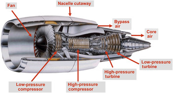
The earliest turbine aeroengines, the von Ohain engine, called Heinkel HeS 3B, and the Whittle engine, known as Power Jets W.1, first flew in 1939 and 1941, respectively. Reference St. Peter11 Advancements in turbine aeroengines since then have essentially involved improvements in propulsive efficiency, including thermodynamic and aerodynamic efficiencies, and in the materials that enabled higher-temperature performance and more efficient airflow within the engine at high reliability and lower weight. Figure 1 shows a schematic of a large modern turbine aeroengine. Core air is mixed with fuel and burned to power the high-pressure turbine (HPT) and low-pressure turbine (LPT). For a two-spool engine architecture, the LPT drives the fan stage and the low-pressure compressor, whereas the HPT drives the high-pressure compressor. The combustor accepts pressurized air from the compressors, mixes it with fuel, and burns it before discharging it into the HPT. The bypass air flows around the engine core and mixes with the core exhaust stream from the LPT before exiting the engine at the thrust nozzle. Reference Gunston13 Modern engines employ a high-fan-bypass architecture (large fan bypass ratio, which is the ratio of the total mass of air drawn into the engine by the fan to the mass of the air that flows through the core of the engine). Earlier-generation engines had a 4:1 fan bypass ratio, whereas modern engines have more than twice this ratio. Primary factors in improved engine efficiency are this high bypass ratio and increased efficiency in the turbines.
Modern commercial high-bypass engine. Reproduced with permission from Reference Reference Schafrik and Sprague12. © 2004 ASM International.
The distribution of materials in a typical high-bypass engine, the CF6 produced by GE Aviation, is shown in Figure 2 . Reference Schafrik, Ward, Groh and Loria14 Newer engine models generally follow this distribution, except that polymer matrix composites are increasing in usage at the expense of aluminum forgings, with aluminum use decreased by about half. Also, ceramic-matrix composites and titanium aluminides are now being used in lieu of nickel in selected applications in the turbine, although the amount by weight is small enough that the usage of nickel alloys has not changed markedly. The use of new materials will increase as the need for lighter-weight or higher-temperature materials continues.
Material usage by finished weight in the high-bypass CF6 aeroengine manufactured by GE Aviation. Reproduced with permission from Reference Reference Schafrik, Ward, Groh and Loria14. © 2001 The Minerals, Metals & Materials Society.

A crucial aspect of materials usage in turbine aeroengines is controlling thermomechanical processing conditions to minimize material defects. Premium quality is required for rotating components, which often leads to additional processing, such as triple melting of superalloys and hot isostatic pressing of castings to close internal pores; tight processing limits; heightened inspection levels; and detailed record keeping of each process step. Design engineers do not use average properties for their designs; rather, they conservatively use properties three standard deviations worse than average (i.e., at the minus-three-sigma [–3σ] level) to account for processing variation. (Material properties usually follow a Gaussian statistical distribution, although some properties, such as fatigue, need to be plotted on a logarithmic scale to bring out the bell-shaped curve.)
One approach to improve materials capability for use in turbine engines is to reduce processing variations, thus increasing –3σ property limits. Material developments that lead to increased average property values without appreciably improving the –3σ property limits do not necessarily result in useful improvements. This is the primary reason for the focus with propulsion materials on understanding the sources and reducing the amount of material defects and has been a key motivation for the development of process modeling.
Materials considerations: Airframes
New alloys and tempers across aluminum, titanium, and ferrous systems have been continuously evolving since the start of the use of metal structures in aircraft. Although some tailoring of alloys has been achieved to improve performance, especially corrosion resistance, and to reduce cost, this has abated to some extent because of the loss of design acreage to CFRP. CFRP for major structures first played a significant structural role on commercial aircraft on the Boeing 777 (B777). (The first major use was on the Lockheed Martin B-2 bomber.) The skins and some of the internal structures on the horizontal and vertical stabilizers were fabricated from CFRP and have performed well, with low maintenance. That success convinced Boeing to fabricate virtually the entire fuselage, wing, and empennage skins and much of the support structure of the successor B787 aircraft from CFRP.
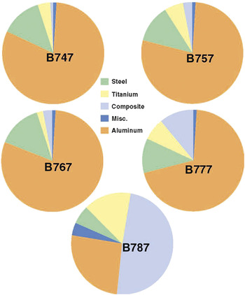
This evolution is illustrated by the change in the materials distribution of major structures on Boeing aircraft, with the amount of composite structure increasing with each new model, taking a major step with the B777 ( Figure 3 ). With increasing composite utilization, use of titanium has also increased because of its galvanic, stiffness, and thermal-expansion compatibility with graphite composite and the development of high-strength alloys to compete with steel in landing-gear structures. Titanium accounted for 3–5% of the structural weight on earlier aircraft, but accounts for approximately 15% for new composite-intensive designs. Aluminum alloys have experienced the largest reduction in use, from approximately 80% of the structural weight on earlier aircraft to about 25% on the 787 Reference Boyer, Slattery, Chellman, Phelps, Niinomi, Akiyama, Ikeda, Hagiwara and Maruyama15 (see Figure 3).
Distributions of structural materials used on selected Boeing commercial aircraft.
In the past, many aerospace alloys were developed by empirical methods. In contrast, integrated computational materials engineering (ICME) allows researchers to optimize alloy compositions and thermal processing to achieve novel materials more quickly and at lower cost. Thus, ICME is being extensively pursued in research and manufacturing facilities worldwide. (See the article in this issue by Xiong and Olson for an example of the use of ICME in materials design.)
Aluminum alloy development
The primary structural aluminum alloys have been the copper-containing 2XXX alloys (starting with 2024) and the zinc-containing 7XXX alloys (starting with 7075). These alloys are still used today. Although these alloys have been modified to improve their strength and toughness, the development of newer alloys such as 7150 and 7055 along with improved tempers has resulted in higher strengths and improved corrosion resistance.
Figure 4 illustrates improvements in the properties of 2XXX- and 7XXX-series alloys. Significant strides have been made in improving both the static and fracture properties of each alloy. Many of these goals were achieved by reducing the permissible levels of impurities, in particular iron and silicon, which reduces the volume fraction of coarse second-phase particles. Because these secondary phases are often the nucleation sites for fatigue damage and fracture, improved purity levels led to more damage-tolerant variants of the well-known alloys, for example, alloy 2024 progressed to 2124, 2224, and ultimately 2524.
Evolution of properties improvements in conventional 2XXX- and 7XXX- series alloys. Note: ksi, kilopounds per square inch (1 ksi = 6.9 MPa, 1 ksi in.1/2 = 1.1 MPa m1/2).

Strength improvements were accomplished through improvements in thermomechanical processing, including all elevated-temperature processing from ingot breakdown, rolling of plate, forging, extrusion, and so on, plus the final heat treatment. However, the increased use of composites, which have replaced many of the aluminum applications, has driven the industry to make more significant properties improvements, leading to the development of more competitive third-generation aluminum–lithium alloys.
First- and second-generation alloys had higher lithium contents, which was beneficial in terms of reducing density. Some additional potential benefits of lithium were improved strength, modulus, corrosion resistance, and fatigue and damage tolerance. However, not all of these potential benefits were realized, and some of the more significant issues with these alloys included low short-transverse fracture toughness, high anisotropy, and casting challenges.
These issues were largely overcome by third-generation airframe alloys, primarily based on the aluminum–copper–lithium system with lower lithium contents, targeting strength improvements with modest reductions in density. Incorporating minor levels of elements such as silver Reference Rioja and Liu16 and zinc improves both the strength and corrosion resistance of these alloys. This effort has resulted in improvements in microstructure control through thermomechanical processing and heat treatment to provide the improvements required. Advances continue in this alloy class in terms of increased strength, damage tolerance, corrosion resistance, and thermal stability with reduced density.
Titanium alloy development
Titanium and titanium alloys did not become production materials until the 1950s, under significant government support. Similarly to 2024 aluminum, Ti-6Al-4V was one of the first titanium alloys developed and remains the predominant titanium alloy in the aerospace industry, because of its balanced and robust property set. (Numbers in the alloy name indicate the weight percentages of each alloying addition.) In addition, numerous other titanium alloys have been developed over the years Reference Cotton, Boyer and Tomchik17 that offer a wide range of properties. Ti-6Al-4V has an ultimate strength level of ∼900 MPa with toughness ranging from ∼55 MPa m1/2 to well over 100 MPa m1/2, depending on the annealing temperature. Ti-6Al-2Sn-2Zr-2Mo-2Cr used at a strength level of about 1100 MPa has a toughness of about 100 MPa m1/2, and Ti-10V-2Fe-3Al at about ∼1240 MPa has a typical toughness of ∼55 MPa m1/2.
At present, most alloy development for airframe materials is focused on cost reduction, with relatively few dollars going toward performance improvements. An effort that has been pursued successfully at Boeing is the development of fine-grain Ti-6Al-4V to enable a reduction of the superplastic-forming (SPF) temperature by about 110°C to about 775°C, and a reduction of the SPF/diffusion-bond temperature as well. The resulting reductions of the allowable processing temperatures has several significant advantages, such as a large increase in die life, a decrease in surface contamination, and much greater comfort for the operators who must transfer the sheets into and out of the press upon completion of forming. Reference Sanders, Hefti, Bryant, Zeng, Guo, Gai and Li18 Titanium is the only structural material with an alloy such as Ti-6Al-4V that is superplastically formable in sheets and, to a lesser extent, plates using standard production methods. Other alloy systems require special chemistries or special processing, increasing costs, and do not have the formability of Ti-6Al-4V.
Another area being studied is additive manufacturing, again to reduce component costs. Reference Boyer, Williams, Wu, Clark, Qian and Froes19 (See the articles in this issue by Babu et al. and Bandyopadhyay et al. for more information on additive manufacturing.) Both powder and wire input stocks are being evaluated utilizing laser-beam, electron-beam, and plasma-transferred-arc energy sources. Because input stock is significantly more expensive than wrought forms, the key savings would result from reducing the buy-to-fly ratio.
Some suppliers have estimated that quite significant cost savings could be achieved using this technology. However, one serious challenge is the nondestructive testing (NDT) of additively manufactured shapes. Initial applications will likely be for components with large fatigue and crack growth design margins. These would not be flight-critical and would provide the opportunity for suppliers to demonstrate that they can provide a product of consistent quality with on-time deliveries. As development proceeds, suppliers could develop sufficient fatigue and NDT data to provide customers the confidence they need to consider this technology for more critical applications. Current studies on additively manufactured parts are primarily focused on Ti-6Al-4V.
Another potential benefit of additive manufacturing is the opportunity to vary the material composition at different locations within a part. If higher strength is required in a given location, for example, but is not desirable over the entire part because of a corresponding loss in fracture toughness, one could modestly increase the oxygen or iron content in that location without changing the properties through the rest of the part.
Powder metallurgy also offers the opportunity to develop materials of much higher strengths than are possible using ingot metallurgy. Many of the most potent alloying additions to improve strength are difficult to melt because of segregation issues. This might not be an issue with powder products, however, as powder particles cool quite rapidly.
In the United States, performance improvements are being pursued through Air Force Research Laboratory-sponsored Materials Affordability Initiative (MAI) programs. These are research collaborations with industry through which each company commits funding to pursue common goals. One such initiative is alloy additions to alloys such as Ti-6Al-2Sn-4Zr-2Mo and β-21S (Ti-15Mo-3Al-2.7Nb-0.25Si) to improve the elevated-temperature and creep strengths with a concomitant increase in oxidation resistance.
Ferrous alloy development
In general, steels offer the highest strengths for commercial metallic structures and span a limited number of applications in aircraft such as landing gear, flap tracks, actuation components, and systems. The highest-tonnage ferrous alloy used for airframes is the 4340M (or 300M) alloy, also referred to as a high-strength low-alloy (HSLA) steel. This alloy is used at a minimum tensile strength of 1930 MPa with a toughness of ∼60 MPa m1/2. This chromium–molybdenum steel alloy was used for most of the landing-gear structures prior to the 1990s. For new commercial aircraft designs, β-titanium alloys have replaced steels in many of these applications.
Since about 2000, landing-gear structures for US Navy aircraft have had to meet a minimum fracture toughness of 110 MPa m1/2. This requirement resulted in the development of AerMet 100 by Carpenter Technology Corporation (Carpenter), which meets the 1930 MPa ultimate strength requirement with a minimum toughness of 110 MPa m1/2. This is not a stainless steel; it has corrosion characteristics similar to those of 300M, but with a minimum toughness about twice that of 300M. Reference Novotny and Maurer20 It is used for applications such as the main landing gear on F-18, F-22, and F-35 fighters and the arrestor hook on the F-35. Carpenter also developed AerMet 310, which has the capability of being heat-treated to over 2000 MPa, still with a toughness superior to that of 300M. Although the improvements in mechanical properties significantly improved performance, the lack of stainless corrosion properties limited applicability because of customers’ desires to reduce maintenance.
Corrosion is a significant issue for steel landing-gear structures. About every 7–10 years, the landing gear must be removed from the aircraft and cleaned. Specifically, cadmium and chromium plating must be chemically removed and the landing gear refurbished to remove any rust or pits, after which the part is reassembled. This takes considerable time, effort, and expense, compounded by the loss of aircraft service during maintenance.
Stainless steels are also used on airframes, and their usage has been increasing since about 2000 with the development of higher-strength grades. A driving force for their development is an interest in extending the time required between refurbishments of the landing gear. These alloys have high nickel and chromium contents, providing good corrosion resistance. Alloys such as 15-5PH (precipitation hardening) and PH13-8 stainless steel alloys provide corrosion resistance, but their strength until recently was limited to approximately the 1035–1520 MPa range. Carpenter developed Custom 465 as part of an effort to achieve higher-strength stainless steels that can be heat-treated up to the 1930 MPa strength level as a direct replacement for 4340M. This would mitigate the corrosion issue and eliminate the need to use undesirable cadmium for corrosion protection. At this stage, Carpenter’s Custom 465 has been heat-treated to ultimate tensile strengths of ∼1655–1795 MPa with the performance of a “true” stainless steel. The resulting parts have been used by major aircraft manufacturers worldwide for applications such as torque tubes, pneumatic cylinders, braces, struts, fuse pins, and flap tracks. Carpenter also reports making progress on a new stainless steel alloy, Custom 565, that can be heat-treated to very close to the 1930 MPa target. Reference Midha and Wert21
Using an ICME approach (see the article in this issue by Xiong and Olson), QuesTek Innovations developed two new stainless-steel-type alloys: (1) Ferrium S53 (AMS 5992) has a minimum tensile strength of 1930 MPa, matching that of 300M, with better corrosion resistance than the latter alloy. This was the first ICME-designed and qualified alloy to fly (in December 2010), when it was used on landing gear on the Northrop T-38 aircraft. (2) Ferrium M54 steel (AMS 5616) was designed as an ultrahigh-strength and high-fracture-toughness steel (minimum value of 110 MPa m1/2) with high resistance to stress–corrosion cracking. M54 has been qualified by the US Navy for safety-critical hook shanks on the T-45 trainer and is in production for future spares. Reference Grabowski, Sebastian, Olson, Asphahani and Genellie22
Two ultrahigh-performance carburizable steels have also been designed to replace AISI 9310 and Pyrowear alloy 53 because of their higher strength, toughness, surface hardness, and fatigue and temperature resistance. Ferrium C61 (AMS 6517) has a typical ultimate strength of 1655 MPa and is being qualified for the transmission shafts of Boeing’s Chinook helicopter upgrade, allowing for increased power density with the existing geometry. Ferrium C64 (AMS 6509) is a higher-hardness alloy that is being qualified for future helicopter transmission-gear steels across the US Army and Navy. Reference Grabowski, Sebastian, Olson, Asphahani and Genellie22
Utilization of nickel-based alloys on commercial airframes has been minimal; they are included in the miscellaneous category in Figure 3. Inconel 625 is used, mostly as a sheet-type product, in the annealed condition at a minimum tensile strength of 827 MPa at temperatures of about 700°C and sometimes slightly higher, primarily for plug and nozzle applications in the engine exhaust area. (This section of the aircraft is separate from the engine propulsion unit and contains, shapes, and directs the engine exhaust plume.) It is also used for brackets and high-temperature ducts. Inconel 718 is used in the solution-treated and aged condition at a tensile strength of 1240 MPa in the nacelle area at temperatures up to 650°C. It is also used for high-strength fasteners at minimum tensile strengths of 1520 MPa. The primary product forms are sheet, high-pressure ducts, and bar.
Composites development
All of the potential benefits of using structural composites as an alternative to metallic structures have been attained in varying degrees, based on experience with composite materials in aircraft. However, there are two open issues affecting composite material selection: (1) overall cost trends and (2) long-term maintainability and repairability.
The first composites used were “wet-layup” composites that impregnated dry fiber with polyester resin (much like for boats). These wet layups required high skill levels and, once the resin was mixed, a short-fuse process. The Boeing Stratocruiser long-range airliner achieved a 20% weight savings over metal ducting by using a fiberglass composite. Supplier pre-impregnated fabrics (called prepregs) that provided consistent resin content and eliminated the messy process of wet layup were first used in 1961. The B727 aircraft utilized a first-generation fiberglass-reinforced cured epoxy composite for radomes and fairing panels. The B737 aircraft used both a first-generation fiberglass-reinforced 175°C-cure epoxy in the hot areas and a second-generation fiberglass-reinforced 120°C-cure epoxy (rubber-toughened/self-adhesive) on radomes, fairings, and control-surface cover panels, mainly with a honeycomb core. The B747 used similar materials in similar applications on a much larger scale. The progression of composite development at Boeing is shown in Figure 5 .
Timeline of composites development on Boeing aircraft. Note: CFRP, carbon-fiber-reinforced polymer; GRP, glass-reinforced plastic; ACEE, Aircraft Energy Efficiency; B, Boeing; DC, Douglas Commercial; MD, McDonnell Douglas; NG, Next Generation.

The introduction of carbon fibers in commercial aircraft came about as a result of a NASA program (1975–1985) in collaboration with Boeing, McDonnell Douglas, and Lockheed, called the Aircraft Energy Efficiency (ACEE) Program, to design and fabricate CFRP parts. Among the parts manufactured through this program were B737 spoilers; a B727 elevator; and a B737 horizontal stabilizer torque box, where the latter was the first primary structure made from CFRP by Boeing. The service experience for these parts was excellent, with the horizontal stabilizer torque boxes still in commercial service.
The success of this effort led Boeing to employ CFRP on the B767 aircraft using the concepts developed through the NASA program. The inboard ailerons, elevators, and rudders used the same material and design as the ACEE B727 elevator, which used a standard-modulus carbon fiber with an untoughened 175°C resin cocured with aramid paper honeycomb core to make panelized skins, spars, and ribs that were bolted together. The B737 spoilers and outboard ailerons fabricated within the NASA program were made from polyacrylonitrile-based standard-modulus (220 GPa) carbon fibers reinforced with 120°C- and 175°C-cure epoxy matrixes. This yielded a full-depth aluminum honeycomb core with precured skins bonded secondarily.
The B777 empennage and floor beams were fabricated using intermediate-modulus (290 GPa) carbon-fiber prepregs for primary structure. In addition to the higher modulus, these prepregs had significantly better impact resistance. The success here then led to utilization of CFRP for wing, empennage, and fuselage skins for the B787.
Other types of composites are also being evaluated. Titanium–graphite is a combination of titanium foil (Ti-15V-3Cr-3Al-3Sn) and carbon-fiber epoxy, which improves the impact resistance and bearing strength of the laminate. Another fiber-reinforced polymer–metal composite is a combination of aluminum sheets and glass fiber/epoxy. The fiberglass improves the crack-growth (damage-tolerance) performance of the aluminum.
As a general rule, composite parts are lighter than their aluminum counterparts, but their costs have historically been significantly higher. One way to offset this disadvantage is to reduce the part count. Composites provide the capability to bond many smaller parts into a more monolithic structure, which reduces the number of fasteners. If done properly, the cost of the resulting monolithic part is less than that of fabricating and assembling multiple parts to form a metallic structure.
Materials considerations: Aeroengines
Traditionally, turbine-engine fan blades have been made from titanium, usually forged Ti-6Al-4V, attached to a forged titanium disk that is also typically Ti-6Al-4V. This alloy has an excellent balance of mechanical properties, including ultimate tensile strength, ductility, and fatigue resistance, and can be readily forged, heat-treated, and machined. Smaller-diameter engines use solid titanium blades, whereas larger-diameter engines use hollow titanium blades that can be made by an SPF/diffusion bonding process.
Large engines, which can have fan blades with lengths well in excess of 1 m, can be made from polymer matrix composites (PMCs), usually carbon fiber in a toughened epoxy matrix. These composite blades, such as those on General Electric’s GE90 engine (which powers B777 models up to the B777X), GEnx engine (which powers the B787), and GE9x engine (which powers the B777X), are lightweight and stiff and exhibit superior fatigue life. Reference Stephenson23 PMC blades typically have a bonded leading edge of Ti-6Al-4V or steel to allow the blade to sustain a bird-ingestion event without catastrophic failure. Higher-strength titanium alloys are sometimes employed for fan disks if greater fatigue capability is desired or higher inlet air temperatures are expected. In these cases, alloys such as Ti-6Al-2Mn-4Zr-2Sn are considered even though they are heavier and more challenging to process because of their complex chemistry and higher strength. Fan cases are typically produced from cast aluminum 2219 or stainless steels, but more recent engines have employed PMC fan cases for weight savings, added stiffness, and corrosion resistance. The low-pressure compressor also uses titanium alloys for airfoils and disks, including the workhorse Ti-6Al-4V.
The aft portion of the high-pressure compressor operates beyond the temperature capability of titanium alloys, and thus, nickel-based superalloys are employed, although higher-strength and higher-temperature-capable titanium alloys such as Ti-17 and Ti-6Al-2Mn-4Zr-2Sn (Ti-6-2-4-2) are used for the cooler early forward stages The temperatures in the rear stage of the high-pressure compressor in a modern engine with a high compression ratio can require cast superalloys for creep resistance and powder superalloy disks for high-temperature creep and fatigue resistance. Reference Leyens, Kocian, Hausmann and Kaysser24
The outer case of the combustor must resist high temperatures and high pressures from the combustion of jet fuel. It is typically produced from a nickel-based superalloy, such as alloy 718 or Waspaloy, for higher-temperature applications. These cases are usually ring-rolled to impart added strength. The inner liner, which is a shield to protect the case from direct contact with the combustion flame, is usually made from cobalt sheet material such as HS188 or nickel-based superalloy such as Hastelloy X. Development work has been done on producing the liner from SiC/SiC ceramic matrix composite (CMC), but this is only now being commercialized. New cobalt alloys that are precipitation-strengthened have shown potential, but they have yet to be scaled up and commercialized, and the optimum chemistry is still being determined.
The high-pressure turbine (HPT), which is immediately downstream from the combustor, has the highest gas-path temperature in its first stage. The temperature in modern jet engines can be in the range of 1350–1450°C or higher; these temperatures approach or exceed the incipient melting point of the nickel-based superalloys used for the nozzles and blades of the HPT. Therefore, these components are internally cooled with air that is bled from an intermediate stage of the compressor. They also have a thin insulating layer of a thermal barrier coating (TBC), typically yttrium-stabilized zirconia. This TBC is applied over an oxidation protective layer, such as MCrAlY (where M can be one or more of the elements iron, nickel, and cobalt), a nickel aluminide coating, or a platinum aluminide coating. (See also the article by Clarke et al. in the October 2012 issue of MRS Bulletin. Reference Clarke, Oechsner and Padture25 )
The airfoils are cast either as a directional solidified microstructure (with grains aligned parallel to the blade longitudinal axis) or, more commonly in modern engines, as single crystals, to impart maximum resistance to stress rupture. Reference Gell, Duhl, Giamei and Tien26 The shrouds surrounding the tips of the HPT blades have been made from single-crystal nickel-based superalloys, but recent developments have shown that SiC/SiC CMC would offer advantages in terms of weight savings (one-third the density of nickel), higher operating temperature, and increased durability. Reference Grady27 These CMC shrouds are currently being qualified for GE’s LEAP engine, the successor engine to the CFM56. 28 The first-stage disk in the HPT is typically made from a powder nickel-based superalloy to provide the highest strength at the operating temperature. These materials are so strong that they must be isothermally forged at a low, superplastic strain rate. Reference Ruble and Semiatin29
The blades of the low-pressure turbine (LPT) are typically nickel-based superalloy castings. In the newest engines, such as the GEnx and LEAP engines, the rear stages of the LPT can be cast γ-titanium aluminide, Ti-48Al-2Nb-2Cr, because this material, at half the density of nickel, offers significant weight savings with no detriment in properties; a portion of the weight savings is due to the smaller-sized disk required to carry the weight of the blades. Reference Bewlay, Weimer, Kelly, Suzuki, Subramanian, Baker, Heilmaier, Kumar and Yoshimi30 The disks and casing are typically a nickel superalloy such as alloy 718 or Waspaloy.
Looking to the future, the need for improved materials and processes that enable further developments in propulsion systems will continue unabated, with an imperative to reduce the time to develop, qualify, and deploy the improvement. Typical timelines for developing and qualifying a new material have been on the order of 10–20 years or more. 31 Design engineers can conceive a design and analyze it within a matter of weeks; the materials community has taken years to accomplish similar tasks in their technology area. Reference Schafrik and Sprague32
Computational models have been important tools in shortening development time because, properly employed, they can estimate material properties and assist in the development of optimum materials processing routes. An exponential increase has occurred in the use of modeling tools in the aerospace materials community for metallic materials, Reference Fink, Miller and Konitzer33 with tools evolving from standalone use for specific problems to proactive use to aid accelerated development programs. A similar effort is occurring for composite materials.
As an example of what is possible, GE Aviation successfully developed a low-rhenium nickel-based alloy for a single-crystal turbine blade alloy in two years, from start to full engine qualification, versus the four to six years normally required for modifying the chemistry of an existing alloy. Modeling tools that supported the research and development efforts were an important factor in this accelerated program. Reference Fink, Miller and Konitzer33
Future directions in cyberinfrastructure should include (a) qualification testing that incorporates an understanding of the behavior of a material so that fewer tests need to be performed; (b) cybermodeling tools that seamlessly perform multiscale, multiphenomenon analyses; and (c) a cyberinfrastructure that supports the materials ecosystem, including model repository, database storage and retrieval, access control for collaborating groups, and data visualization tools.
Other materials considerations
Certain other considerations, of which inexperienced engineers might not be aware, can have a significant impact on functionality. For instance, aluminum alloys and low-alloy steels are active in the galvanic series, whereas titanium- and nickel-based alloys and stainless steels are noble. If an active material is in contact with a noble material in the presence of moisture, a galvanic corrosion cell will be initiated, with the active material being corroded. Titanium- and nickel-based alloys and stainless steels do not create a corrosion issue when in contact with each other in the presence of moisture, although localized pitting can occur under certain circumstances.
Corrosion was not a complex issue to handle in the past, because a coat of primer or primer and a topcoat on each material often solved the problem. However, new regulations that limit the use of coatings containing hexavalent chromium will add to the challenge of mitigating corrosion.
Contact with carbon fibers in CFRP composites, aluminum alloys, and low-alloy steels is an even more significant issue, as direct contact with the carbon fibers in a moist environment can set up a very active corrosion cell. In this case, a good solution is to separate the metal from the CFRP with a layer of fiberglass.
With regard to aluminum alloys, although higher-strength 2XXX and 7XXX alloys are not fusion-weldable, they are weldable by solid-state friction-stir welding. Where fusion welding is required, 6XXX series alloys are generally used, although welding them is still not necessarily easy. Unless strength is critical and corrosion is not a concern, the alloys are used in an over-aged condition (T7), as opposed to a peak-temper T6 age. Aluminum alloys are not used at very high temperatures, as they will over-age. The 2XXX T3- and T4-type and 7XXX alloys should generally be limited to ∼90°C. The 2XXX-T6 or -T8 tempers could be considered up to ∼175°C. The 2X19 series alloys can be used at temperatures above ∼175°C. Aluminum–copper–lithium alloys can provide some properties advantages up to this temperature.
Titanium alloys have excellent corrosion resistance for aerospace applications. They have a very thin, tough oxide surface that provides this corrosion resistance. However, corrosion/hydrogen embrittlement can occur if hot hydraulic fluid in commercial aircraft comes into contact with titanium. The problem is due to an additive used for commercial aircraft to raise the flash point of the hydraulic fluid; military aircraft do not use this additive, so they do not encounter this problem. Hydrogen accumulation can occur at temperatures in excess of ∼130°C. Therefore, most titanium alloys are not used in areas of potential hydraulic fluid leaks in hot structures, such as struts, unless it can be shielded. The exception is β-21S, which is the only titanium alloy used in the aerospace industry that is not affected by this problem.
Titanium alloys are used from subzero temperatures to as high as ∼600°C. Titanium is unique in that some sheet alloys, such as Ti-6Al-4V, are superplastically formable using standard manufacturing procedures. For the other alloy systems, special alloys or processing have been developed to enable this capability, but they cannot achieve the same elongations observed with Ti-6Al-4V sheet.
Titanium alloys are generally difficult to machine, costing about 10 times as much as the machining of aluminum alloys. Stiff machines with high horsepower are required. The cutters must be kept sharp: Their lives are usually measured in minutes, as opposed to hours for aluminum. It is very difficult to grind titanium without inducing high residual stresses in the parts, which are detrimental to fatigue performance. Sanding should also be done with care. During sanding, extensive sparks can be thrown up. This must be minimized because, if one or more hot sparks land back on the titanium, they bond back in and are contaminated with interstitial elements, also resulting in a substantial fatigue debit. Care must also be taken with regard to the motion of a contacting surface against titanium, because titanium galls very easily. Some type of lubricant or coating must be used to eliminate this problem.
The increased use of CFRP composites has played a key role in titanium usage. The fact that titanium has a low coefficient of thermal expansion and is compatible with the graphite fibers in the composite in the presence of moisture, in conjunction with its low density and high strength, make it an ideal material for interfacing with composites.
HSLA steel must have a corrosion-resistant coating to minimize corrosion when not being worked on. The maximum use temperature should be less than ∼290°C, or over-aging can occur. These materials machine readily, except for the higher-strength alloys, in the range of 1930 MPa. Most of the machining is done prior to the final heat treatment. Once the final aging is done and the material is at full strength, machining must be done very carefully to prevent heating and the formation of untempered martensite, which is very brittle. When HSLA steels are chrome plated for wear resistance, there is the possibility of hydrogen embrittlement. The plated material must be baked at 175°C to drive out the hydrogen if pickup did occur: It takes only a few parts per million of hydrogen to create a problem. A notched specimen will be held under load after the bake out to ensure that embrittlement did not occur.
Conclusions
The selection of airframe materials and processes is a complex endeavor, requiring a balance among myriad design, reliability, and maintainability requirements. Materials quality and fabricability must be given close scrutiny by designers in partnership with fabricators and part manufacturers to ensure that the design is achievable at a reasonable cost. Ultimately, design and build quality and cost are critical factors in light of the tremendous global competition in the aviation industry.
Materials for aeropropulsion applications must likewise meet demanding property requirements and also demonstrate high reliability in a severe operating environment. This requires a detailed understanding of the way in which a material responds to various degradation mechanisms that are encountered in service, as well as knowledge of the variations in material properties that result from defects introduced during processing.
There is a need for continuing improvement in materials to support both airframe and advanced engine designs, with the expectation that the materials community can significantly shorten the development and implementation time without increasing development risk by taking advantage of computational tools.
Acknowledgments
The authors acknowledge significant efforts from several parties for this article. We thank Drs. J. Grabowski and A. Asphahani from QuesTek Innovations for their assistance with the steel alloys, Tim Armstrong and Mike Schmidt from Carpenter Technology Corporation for updates on the AerMet and stainless steel alloys and the higher-strength stainless steel, and B. Reichlinger of The Boeing Company for assistance with the aluminum alloy discussion. The authors appreciate review of the composite content by Eric Creggor.


