

An archaeological evalution of the Olmec “royal tombs” at La Venta, Mexico
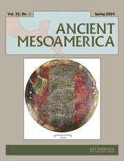
It is generally accepted that the Olmecs, a people of Mexico's southern Gulf Coast in the Early to Middle Formative periods (ca. 1200–400 b.c.), developed early complex societies. Although their level of sociopolitical organization has long been debated, material evidence for hierarchy is compelling, and the Olmecs have been called Mesoamerica's “first civilization” (e.g., Bernal Reference Bernal, Heyden and Horcasitas1969; Clark Reference Clark1997, Reference Clark, Williams, Mestas and Esparza2009, Reference Clark, Traxler and Sharer2016; Coe Reference Coe1968; Coe and Diehl Reference Coe and Diehl1980:vol. II, p. 147; Cyphers Reference Cyphers and Clark1994, Reference Cyphers, Traxler and Sharer2016; Diehl Reference Diehl2004; Drucker Reference Drucker and Benson1981; González Lauck Reference González Lauck and Clark1994, Reference González Lauck, Benson and de la Fuente1996; Grove Reference Grove1997; Pool Reference Pool2007; Soustelle Reference Soustelle1979). Monumental earthworks characterize the Early Formative primate center, San Lorenzo (ca. 1150–900 b.c.) in modern Veracruz (e.g., Coe and Diehl Reference Coe and Diehl1980; Cyphers Reference Cyphers, Traxler and Sharer2016) and its Middle Formative political successor, La Venta in Tabasco (Figure 1; Drucker et al. Reference Drucker, Heizer and Squier1959; González Lauck Reference González Lauck, Benson and de la Fuente1996). At both sites, archaeologists excavated tons of imported stone objects, including large, basalt sculptures and relief carvings as well as thousands of finely crafted, smaller artifacts of jade, serpentine, and iron ores. The ability to import and display these exotics was apparently monopolized by the uppermost tier of society, believed by some archaeologists to be “kings” (Clark Reference Clark, Traxler and Sharer2016; Freidel et al. Reference Freidel, Schele and Parker1993:430; Pool Reference Pool2007:161). Significantly, the sculptures include realistic images of adult humans (de la Fuente Reference de la Fuente1973) on massive “altars” (bench thrones), statues, and stelae, as well as colossal heads widely believed to be portraits of living paramounts (Coe Reference Coe and Adams1977:186; Grove Reference Grove and Benson1981:65–67) and venerated ancestors (Gillespie Reference Gillespie and Robb1999). This evidence has been interpreted as an elite preoccupation with individual rulers, a rare phenomenon in the New World (Coe Reference Coe, Sharer and Grove1989:77; see also Grove and Gillespie Reference Grove and Gillespie1984).
Map of major Olmec centers on Mexico's Gulf Coast within the Mesoamerican culture area in the Early to Middle Formative periods. Drawing by Volk.
In addition to imagery of likely historical elite persons, another class of evidence for individual Olmec leaders consists of singular tombs. They have been recovered only at La Venta, five of them found in a small mound group labeled Complex A that had non-domestic functions. The Complex A construction phase in which the tombs were deposited dated to the end of the Middle Formative period (“Terminal Olmec,” ca. 600–400 b.c. [Lowe Reference Lowe, Sharer and Grove1989:56–59]), manifesting a late development of “elaborate mortuary practices” not present in the Early Formative (Pool Reference Pool2007:177). Indeed, the initial discovery of these features in the 1940s, along with hundreds of fine jade objects and sculptures, precipitated interpretations of Olmec civilization that still dominate the field (Grove Reference Grove1997:60). Nevertheless, the La Venta tombs also generated significant controversies that continue unabated, starting with the questioned identification of them as “tombs” (Coe and Stuckenrath Reference Coe and Stuckenrath1964:23; Drucker Reference Drucker1952). It is yet unsettled whether they were burials at all, given the general absence of human remains. A separate controversy is whether they represented the resting places for a succession of La Venta's rulers toward the end of the site's occupation. A third point of contention is how the events evidenced by these features figured into the decline and abandonment of La Venta soon after their completion.
These controversies are not insignificant due to the outsized role that presumed “royal tombs” and “royal mortuary rituals” have played in discussions of political organization and ritual architecture at La Venta and by extension, for the Gulf Coast Olmecs more generally. Our objective in this paper is to evaluate the taphonomic and stratigraphic evidence for these features as places of primary burial for a sequence of high-status individuals. Unfortunately, Complex A was badly damaged starting in the late 1950s and, by the following decade, no identifiable surface architecture was present (Heizer et al. Reference Heizer, Graham and Napton1968a:139). Thus, there is no recourse to further excavations or analyses to resolve these controversies. Furthermore, the published reports on the early La Venta excavations (especially Drucker Reference Drucker1952; Drucker et al. Reference Drucker, Heizer and Squier1959; Stirling and Stirling Reference Stirling and Stirling1942; see also González Lauck Reference González Lauck and Clark1994, Reference González Lauck, Benson and de la Fuente1996) have well-known shortcomings (e.g., Coe and Stuckenrath Reference Coe and Stuckenrath1964; Gillespie Reference Gillespie2011). We base our arguments, instead, on information from archived field records, principally among the Robert F. Heizer Papers at the National Anthropological Archives (RFHP-NAA) of the Smithsonian Institution. We enhanced the recorded stratigraphic data with computer-assisted techniques not available to the original excavators to create more accurate, precise, and comprehensive profile and plan drawings as well as 3D representations (Gillespie and Volk Reference Gillespie and Volk2014).
As detailed in the following sections, the preponderance of the taphonomic and stratigraphic evidence supports the conclusion that these features were not formal repositories of the bodily remains of a series of individuals who died years or decades apart. Alternative interpretations of these and related features are therefore warranted, especially to overcome archaeological biases and potentially widen current understandings of ritual and political history at La Venta. In particular, the conventional archaeological practice of “re-presenting” the “non-present past” (Domanska Reference Domanska2006:346), a usually unquestioned discipline-wide method of “enacting knowledge” (Hicks Reference Hicks, Hicks and Beaudry2010:95), deserves further scrutiny. Even as we conclude that twentieth-century archaeologists constructed non-present bodies at La Venta, we should contemplate how and to what effects their absence was materially made present in new forms by ritual officiants in the Middle Formative period.
The five La Venta tombs and their importance
This section reviews the available archaeological evidence for the tombs and related features at La Venta from the 1942, 1943, and 1955 excavations. It then considers later interpretations of their significance in understanding late Olmec civilization and the demise of La Venta.
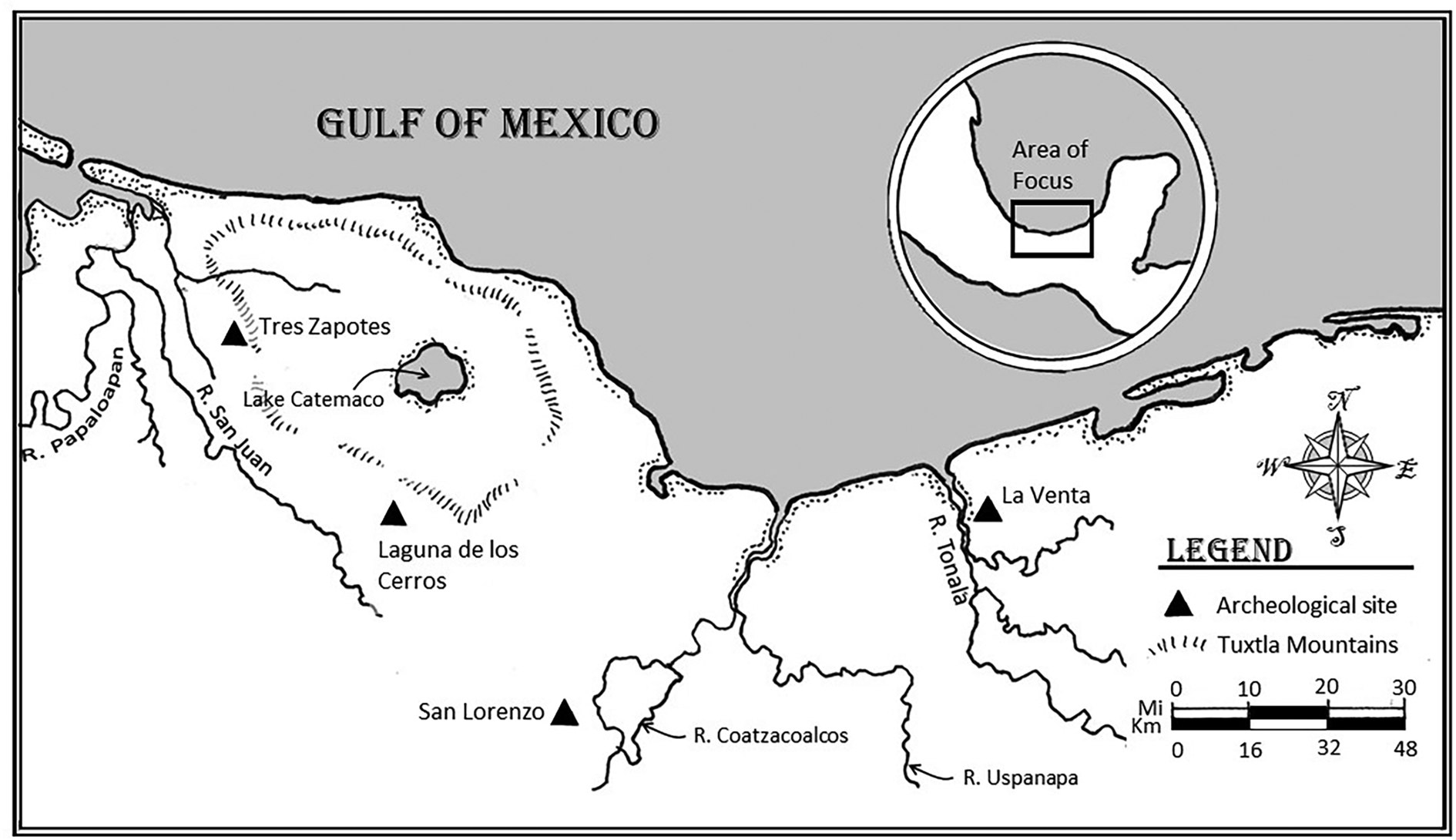
La Venta was the first Olmec capital to be systematically excavated (Grove Reference Grove2014). Following an initial reconnaissance in 1940 by Stirling of the Bureau of American Ethnology to locate reported stone carvings (Stirling Reference Stirling1940, Reference Stirling1943b), a major excavation project was launched two years later, again directed by Stirling and conducted by Drucker. Toward the end of the 1942 project, Drucker placed excavation units in a small area of low earthen mounds (Complex A) north of the now ca. 30-meter high earthen pyramid that dominates the site, Complex C (Figure 2 and Supplemental Figure 1; Drucker Reference Drucker1952; see also Grove Reference Grove1997:58–59, Reference Grove2014:38–42). He opened a shallow north-south trench in the center of the summit of the highest platform mound in Complex A, later labeled Mound A-2. Immediately under the modern surface he and Stirling, who had arrived with his wife, Marion, just at this final phase of the project (Drucker Reference Drucker1952:2), encountered two adjacent stone constructions, thought to have mortuary functions and thus labeled tombs.
Three-dimensional reconstruction of La Venta Complex A (foreground), together with the pyramid (Complex C, background). This image depicts the major structures at different points in time: Mounds A-4 and A-5, the red cap on Mound A-3, and the basalt columns on the Court wall and on the Southwest Platform (SWP) and Southeast Platform (SEP) all date to construction Phase IV. Mound A-2, the Northeast Platform (NEP), the Northwest Platform (NWP), the South-Central Platform (SCP), and the Ceremonial Court are shown as they might have appeared at the start of Phase IV. Mound C-1 is depicted in an eroded state as it was mapped in 1968 (Heizer et al. Reference Heizer, Graham and Napton1968a).
Tomb A
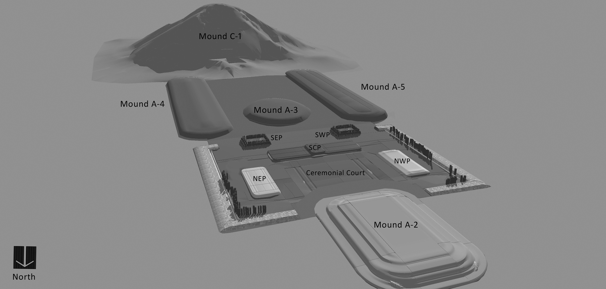
The most impressive of the two was a large, rectangular chamber whose walls and roof were made of two-ton, imported, natural columnar basalt pillars. The tips of the vertical columns that formed its northern side were visible above the ground surface (Drucker Reference Drucker1952:23). Later designated Tomb A and Monument 7, it is worthy of the name: a stone vault approximately 2.2 meters tall within which one could stand upright (Figure 3). Its roof was formed of nine horizontally laid stones supported by uprights on the east, south, and west walls. The north wall, made of five columns tilted against the northernmost roof span, is considered the “front doorway” (Drucker Reference Drucker1952:23; Stirling and Stirling Reference Stirling and Stirling1942:638) or “entryway” (Drucker Reference Drucker and Oehser1975:103). It was from this north side that Stirlings entered to investigate its contents. The chamber was filled with soil, mostly the same bright orange-red clay that enveloped it (Drucker Reference Drucker1952:23). It took a day just to relocate the five columnar basalts that blocked the doorway, but the Stirlings then removed the fill and recovered the artifacts in only two additional days (Stirling and Stirling Reference Stirling and Stirling1942:640–643).
Reconstruction of Tomb A, constructed of natural columnar basalt, without its surrounding matrix as if it could stand upright unaided. The slanting columns leaning against the roof on the north side make up the “doorway.”
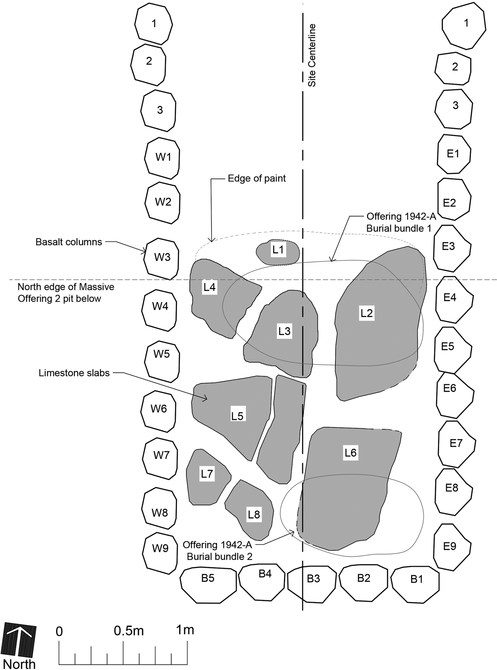
As described by the Stirlings (Stirling and Stirling Reference Stirling and Stirling1942:640), removing the red clay fill revealed a low “burial platform” ca. 30.5 centimeters (“about a foot”) high extending in the “rear [2.44 m] eight feet of the tomb.” It was topped by irregularly placed, clay-covered, imported limestone flagstones that were themselves covered with bright red “cinnabar” (brilliant red pigment was identified as cinnabar in the field records; Figure 4). What else was found on this platform diverges drastically between Drucker's (Reference Drucker1952) and the Stirlings’ (Reference Stirling and Stirling1942) accounts (see also Colman Reference Colman2010:208, 211), a major discrepancy made more frustrating by the absence of published photos or drawings of the artifacts in situ. The two accounts cannot be reconciled, leaving archaeologists to choose one over the other or to ignore the controversy altogether (Table 1). The Stirlings led the excavation (Drucker Reference Drucker and Oehser1975:103), but it was Drucker's responsibility to clean and map the tomb and to describe and categorize the objects found (Drucker Reference Drucker1952). The entirety of the finds in Tomb A were later designated Offering 1942-A (Drucker et al. Reference Drucker, Heizer and Squier1959:Appendix 1).
Plan of Tomb A's interior, indicating the limestone slabs (shaded) atop the low platform in the southern half of the tomb, made from published photographs and field records. The locations of Bundles 1 and 2 are based on Drucker (Reference Drucker1952:Figure 10a). Our project numbered the individual basalt columns making up the east, south, and west walls and the limestone slabs.
Contrasting accounts of Tomb A finds: Stirling (Stirling and Stirling Reference Stirling and Stirling1942:640–642) versus Drucker (Reference Drucker1952:23–26) and Drucker et al. (Reference Drucker, Heizer and Squier1959:Appendix 1).
a Items listed somewhat in order of occurrence in different locations in their account of the excavation of Tomb A.
b “Bundle” assignment.
c List.
d An unpublished 1942 National Geographic Society photo shows three D-shaped pieces and a tubular bead with these two figurines. They are not mentioned here but see reference to beads in Finds 5 and 10.
e There appear to be two mirrors side-by-side in the photograph of finds (Stirling and Stirling Reference Stirling and Stirling1942:Plate I upper).
Drucker's (Reference Drucker1952) report on the 1942 excavations provided the first published plan and profile drawings of the tomb (1952: Figures 9 and 10). His version is more often utilized, possibly for that reason, although others prefer the Stirlings’ narrative account of what was found (Colman Reference Colman2010:108; González Lauck Reference González Lauck, Benson and de la Fuente1996). According to Drucker, heavily coated with red cinnabar paint “were the remains of two bundle burials, each probably containing at least one individual,” spatially separated. Drucker's (Reference Drucker1952:Figure 10) plan view shows Bundle 1 as a large oval area about 1.5 × 1 m in the north (front) half of the platform, and Bundle 2 as a smaller area, about 1 × 0.75 m, tucked in the rear near the southeast corner. His plan view also includes eight limestone flagstones, but they do not match their appearance in the photographs (Figure 4; Stirling and Stirling Reference Stirling and Stirling1942:636).
Importantly, Drucker (Reference Drucker1952:23) observed that there was little left of the “acid-leached bones save for a mass of splinters, stained a dark chocolate-brown color. They appeared to be remnants of long bones mainly, and gave the impression of small light bones, probably of juveniles.” He also noted that in Bundle 2 were some deciduous teeth, another indication of the presence of a child or children. Small objects, mostly of jade, were associated with each bundle, and Drucker (Reference Drucker1952:23–26) listed these accordingly. The 1959 report on the 1955 excavations (Drucker et al. Reference Drucker, Heizer and Squier1959: Appendix 1), however, provides only a summary list of the Offering 1942-A objects by type and does not separate them among two presumed bundle burials (Table 1).
The Stirlings’ report of the 1942 finds was published in an issue of National Geographic that same year, in the form of a narrative of what they found as the matrix was removed. Within an irregular 15.24-cm (6 in) thick layer of cinnabar on the platform, they encountered “mere traces of bones of apparently three persons placed with heads to the south” (Stirling and Stirling Reference Stirling and Stirling1942:640; Stirling Reference Stirling and Oehser1975:305). The red cinnabar gave the impression of being placed inside wrapped bundles, which presumably held the bodies within the tomb (Stirling and Stirling Reference Stirling and Stirling1942:642). With one of these persons were two figurines (catalogued in Drucker's Bundle 1). The Stirlings enumerated about a dozen spatially separated clusters of objects, including milk teeth in the southeast corner. There are vague references to relative positions, but almost nothing more to indicate which objects go with any of the three persons they believed were laid out on the platform. For example, ca. 0.61 meters (2 ft) away from the pair of figurines was a jade replica clamshell, and under it was a jade figurine of a seated female. These two adjacent objects were divided between Bundles 1 (clamshell) and 2 (figurine) in Drucker's Reference Drucker1952 account, and there are other examples where Drucker separated what the Stirlings had put together. Some objects described in one report are not mentioned in the other, including a burned skullcap with a ceramic pot noted only by the Stirlings (Table 1; Stirling and Stirling Reference Stirling and Stirling1942:641). Furthermore, in the National Geographic report only a selection of the artifacts was photographed (1942:Plate 1, upper), in a group referred to as a “cache,” although it includes pieces retrieved from both Tombs A and B as well as Offering 1942-D.
In short, we cannot be certain today which objects were found where in Tomb A in terms of spatial associations, nor the extent and context of human remains. Although there were definite costume ornaments—two sets of earspools according to the Stirlings; a necklace or headdress made of six, real, stingray spines along with a jade replica spine; and several tubular beads—they are not described as being laid out as if arranged on a corpse, even in the Stirlings’ assessment of three individuals laid with heads to the south. If that were the case, this arrangement of artifacts in red “cinnabar” does not match what was encountered in most of the other presumed tombs.
Tomb B
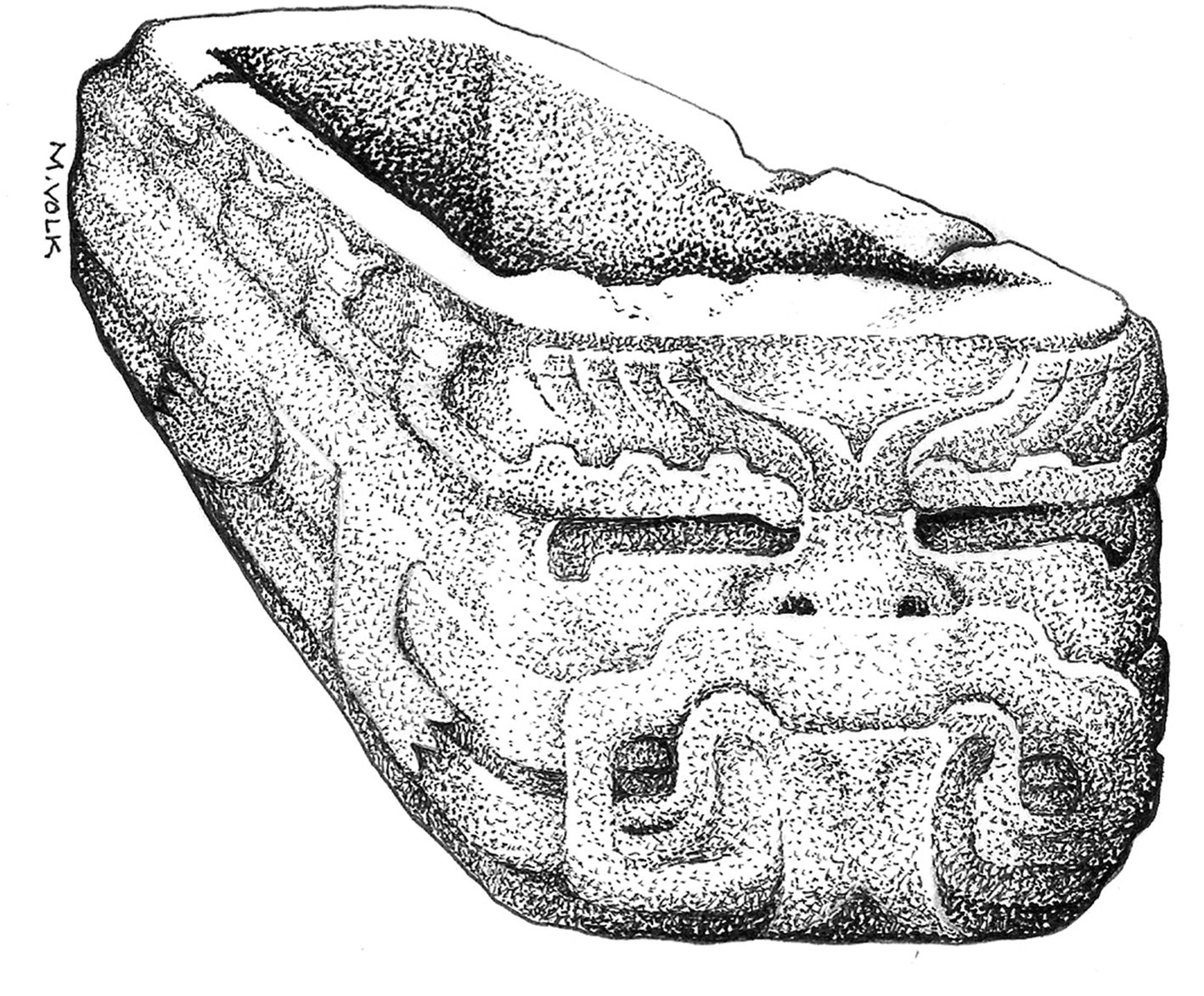
The other stone container on the summit of Mound A-2 consisted of two parts: a 3 × 1 m worked rectangular sandstone slab, cracked in several places, that topped a hollowed-out box, oriented north-south. At 2.81 m long and just over 96 cm wide (Drucker Reference Drucker1952:26), the box was made from a different kind of local sandstone than its cover (Drucker Reference Drucker and Oehser1975:104). Three exterior sides of the box were sculpted in low-relief, giving it the overall appearance of a non-natural legged saurian creature whose head was to the north, facing Tomb A (Figure 5; Stirling and Stirling Reference Stirling and Stirling1942:638). Like Tomb A, the coffer was filled with red clay and sand, and enveloped in red clay. It was later designated Tomb B and Monument 6. Not known at the time is that Tomb B was positioned directly over the center of Massive Offering 2, a single layer of worked serpentine blocks buried at the base of a deep pit excavated through Mound A-2 into the subsoil; some commentators have symbolically linked the two “offerings” (e.g., Pool [Reference Pool2007: 165], following Reilly[Reference Reilly and Kowalski1999:35]). Unfortunately, the sandstone box was also badly cracked and eroded when found. It continued to disintegrate and could not be salvaged (Heizer Reference Heizer1958:202).
Reconstructed drawing of the relief carving on the Tomb B box. Drawing by Volk.
According to Drucker's (Reference Drucker1952:27) field report, six objects were recovered lying on the bottom of the box interior: a serpentine figurine, two jade earspools, each of which was accompanied by a jade pendant, and a pointed jade punch or awl. This assemblage was designated Offering 1942-B (Drucker et al. Reference Drucker, Heizer and Squier1959:Appendix 1). Ten years earlier, in their 1942 National Geographic article, Stirling and Stirling (Reference Stirling and Stirling1942:638), who took responsibility for its excavation as with Tomb A, described the find differently by referencing the relative positions of the objects. They assumed the coffer was a sarcophagus that held the corpse of a single individual laid out wearing regalia. The two earspools with their dangling pendants were spaced just far enough apart to indicate an absent head between them, oriented to the south with feet to the north, while the figurine and piercing instrument lay near the hip. In a delayed response to the Stirlings’ opinion, Drucker (Reference Drucker1952:27) allowed that although “to western eyes,” the box “gave the impression of a great sarcophagus, there was not the least indication that it had been used or even intended for a burial. There were no traces of bone–not even tooth caps or discoloration in the clay–in it.”
Tomb C
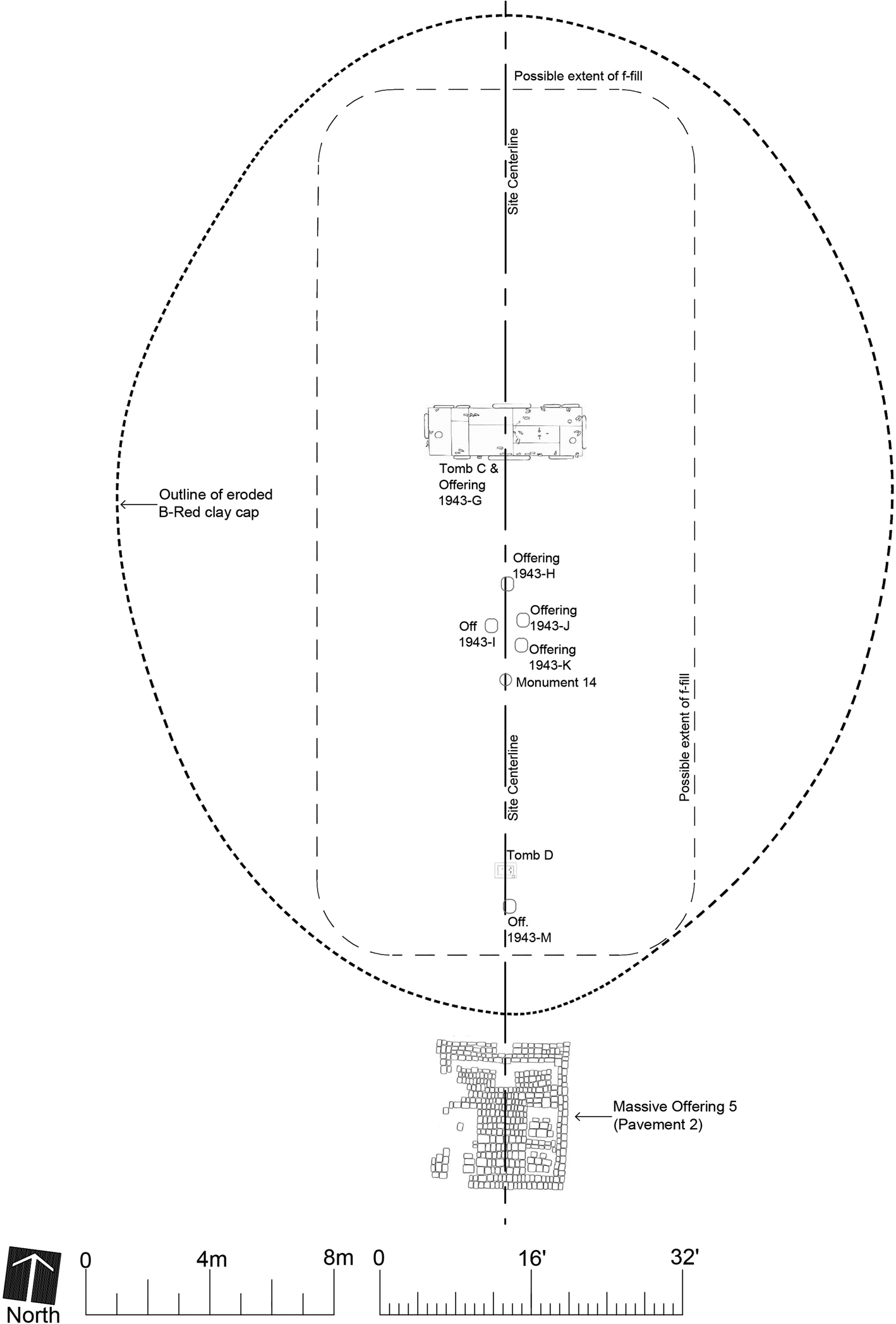
The following year, 1943, Wedel continued the work Drucker had begun (Drucker was serving in the war; Drucker Reference Drucker and Oehser1975:104), again under Stirling's direction. Extending the 1942 trench to the south, he encountered another stone construction in a smaller mound south of the walled Ceremonial Court (Mound A-3; Figure 2) 60 cm below the modern surface. It lay in a north-south alignment with Tombs A and B; this alignment was later designated Complex A's “centerline.” The feature was a very large (5.2 × 1.8 m), rectangular “cist” oriented east-west (Figure 6). Its walls, floor, and roof were made of dressed sandstone slabs; the roof slabs had caved into the red clay fill of its interior, the same matrix that surrounded it (Wedel Reference Wedel and Drucker1952:67–68, Plate 14a). The stone structure was designated Tomb C, and the objects within it comprise Offering 1943-G (Drucker et al. Reference Drucker, Heizer and Squier1959:Appendix 1).
Plan of Mound A-3 showing Tombs C and D along with other caches and finds made in 1943, including Massive Offering 5 south of the mound. The edges of Mound A-3, assumed to have been a single rectilinear mound before it was covered with red clay in Phase IV, are only estimated based on profile drawings in the excavation field notes (RFHP-NAA).
On removing the clay fill, an elliptical layer of brilliant red cinnabar was encountered 20 cm above the stone floor. Around the cinnabar bed were 37 jade celts and three ceramic vessels. Under and within the cinnabar matrix were some 300 artifacts. Most were jade costume ornaments, including two earspools with “earbobs,” beads, pendants, and perforated spangles that were likely sewn to a textile garment (Wedel Reference Wedel and Drucker1952:67–68). In his account of this find in National Geographic that year, Stirling (Reference Stirling1943a:323) indicated that the cist held a single occupant whose bones “had disintegrated long ago.” From the positioning of the earspools, he ascertained that the head that wore them lay to the east, feet to the west, and across the waist area were 62 green jade beads that originally formed a double “necklace” along with a figurine, jade punch, and engraved obsidian core (Figure 7; Stirling Reference Stirling1943a:325; Wedel Reference Wedel and Drucker1952:Figure 22).
Plan of Tomb C, with Offering 1943-G, in Mound A-3, based on Wedel (Reference Wedel and Drucker1952:Figure 22).
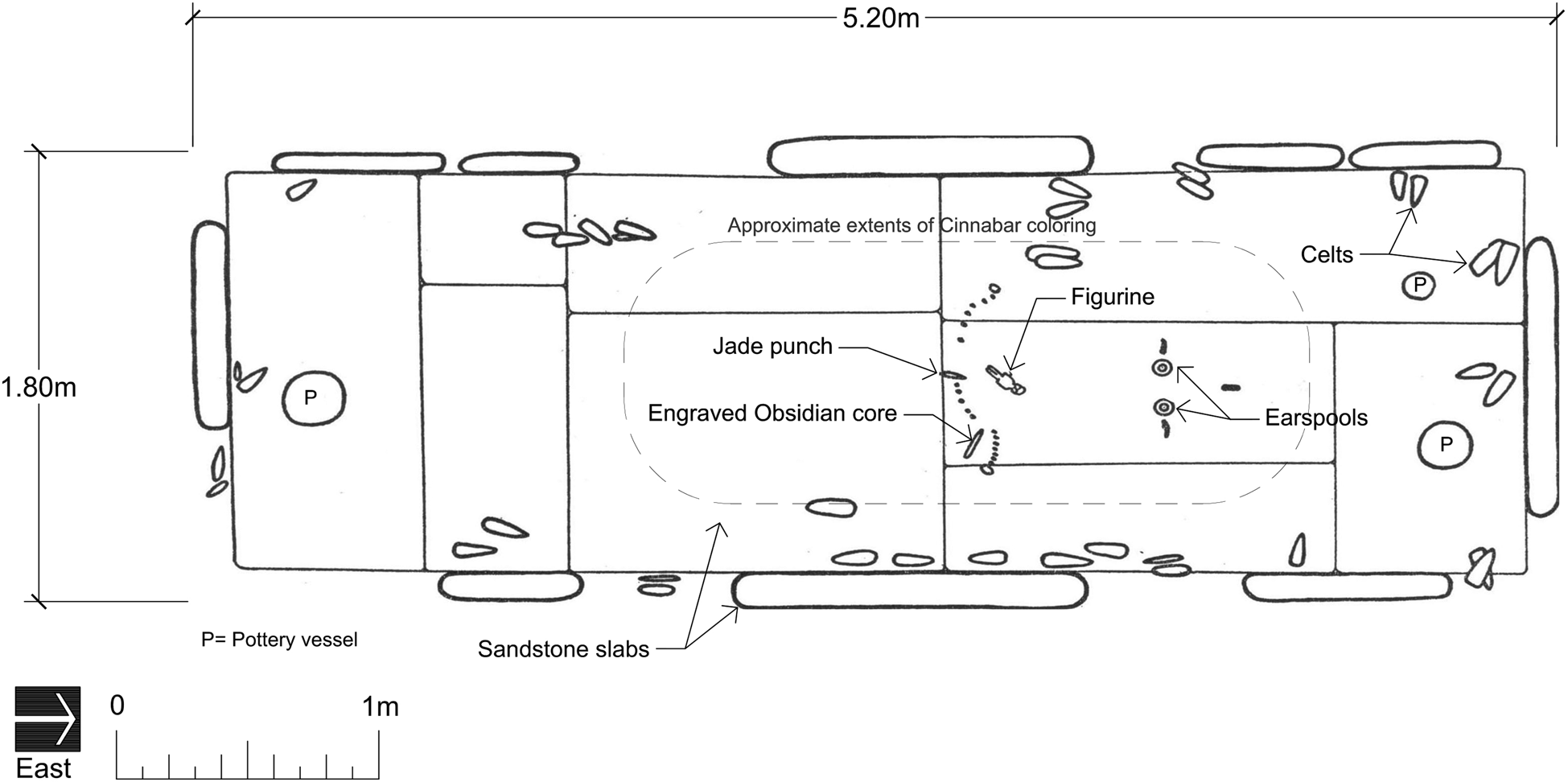
Wedel (Reference Wedel and Drucker1952:71) more circumspectly observed that all these latter objects “lay just above the floor slabs, and were completely surrounded by cinnabar…in such positions relative to each other as to suggest mortuary offerings on a burial.” But, he added, “Despite the most careful examination of this area, however, no trace whatsoever could be detected of bone, of tooth enamel, or of other human remains. There is thus no direct proof that this cist ever actually contained a burial.” His careful plan drawing of the tomb's major contents (Wedel Reference Wedel and Drucker1952:Figure 22) shows the two earspools lying flat on the cist floor, spatially separated as if by a human head, with the “bobs” or appendages arrayed in a north-south alignment away from the head and perpendicular to the presumed body. The beads were positioned in a slightly curved line across the presumed torso.
Tomb D
Also in 1943, within the centerline trench, “Tomb D” was located 13 m south of Tomb C in Mound A-3, although it does not live up to that designation (Figure 6; Wedel Reference Wedel and Drucker1952:73). Cinnabar was encountered about one meter below the modern surface, revealing a rectangular deposit some 30 × 50 cm in extent, with an east-west long axis as in Tomb C. At the bottom of the 22–25 cm thick cinnabar bed were eight jade objects, including two jade ear spools, jade earbobs, and tubular jade beads (Wedel Reference Wedel and Drucker1952:72–73, Plate 15b); altogether they make up Offering 1943-L. The earspools and bobs were arranged as if adorning a head, the bobs splayed out perpendicular to a presumed body. But the deposit was so small it could have accommodated only a child, according to Wedel (Reference Wedel and Drucker1952:73). Stirling (Reference Stirling1943a:Plate IV upper) referred to the Tomb D finds as “pathetic artifacts from a child's tomb.” As with Tomb C, “there were not the faintest traces of human bones, teeth, or other remains in the area” of the cinnabar (Wedel Reference Wedel and Drucker1952:73).
Tomb E
Tomb E was also encountered by Wedel and Stirling in 1943, when they moved 11 basalt columns that had been placed “irregularly” in a general north-south alignment in the space between Tombs A and B on Mound A-2 (Drucker Reference Drucker1952:27; Wedel Reference Wedel and Drucker1952:63). Excavating below them revealed a layer of bright red cinnabar filling an area 3.5 × 1.2 m, about 75 centimeters below the bottom edge of the columns, along with various jade artifacts. In 1942 those columnar basalts had been considered left-overs from the making of Tomb A (Wedel Reference Wedel and Drucker1952:63). Upon digging below where they lay, the 1943 excavators made a connection between the cinnabar feature and its basalt column “cover”; hence its designation as a tomb (Figure 8).
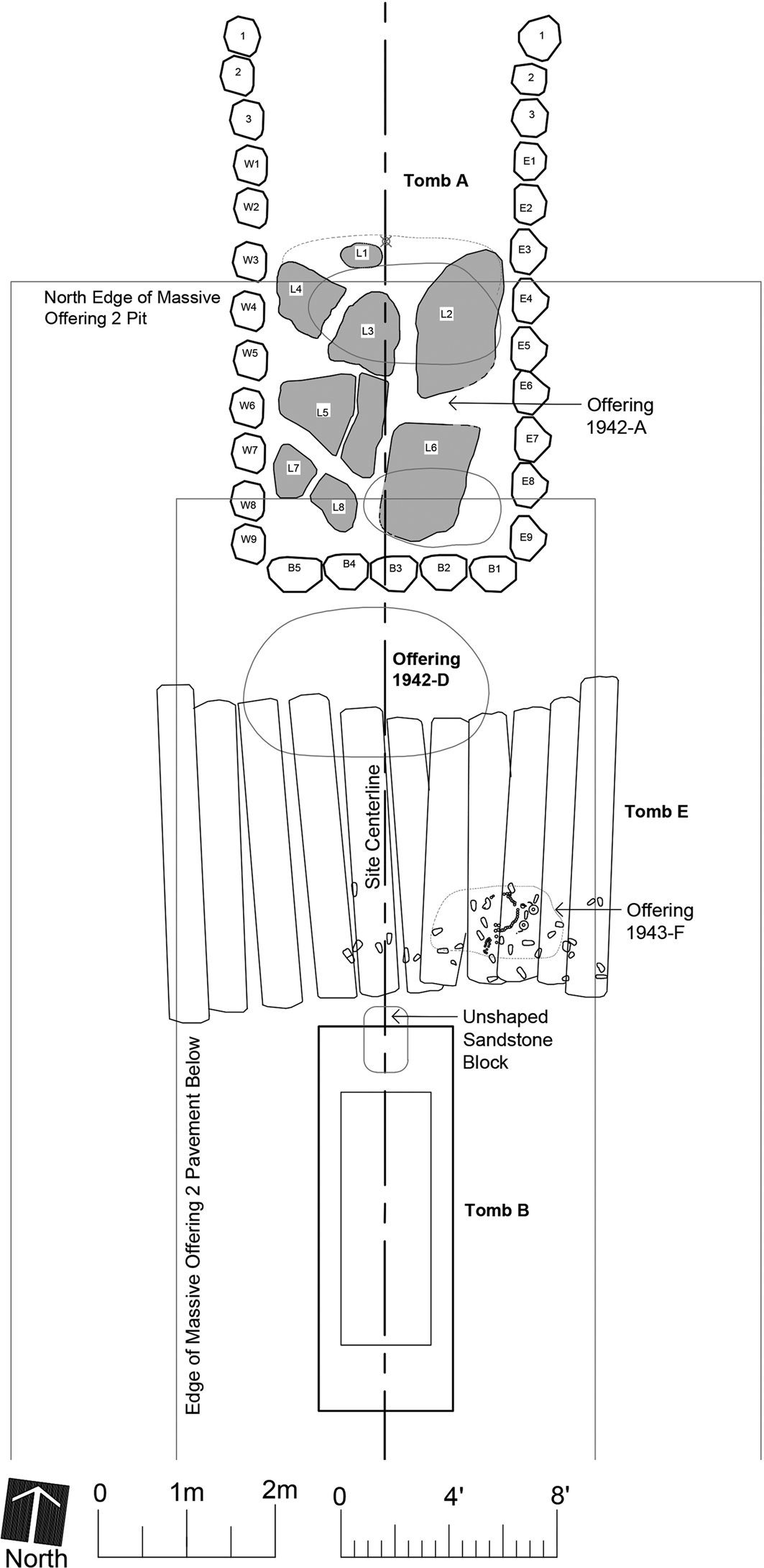
Plan of the central summit of Mound A-2 in construction Phase IV showing the relative positions of Tombs A, B, and E, Offerings 1942-D and 1943-F, and the sandstone block placed in the fill of Massive Offering 2. Note that Offering 1943-F is off the centerline.
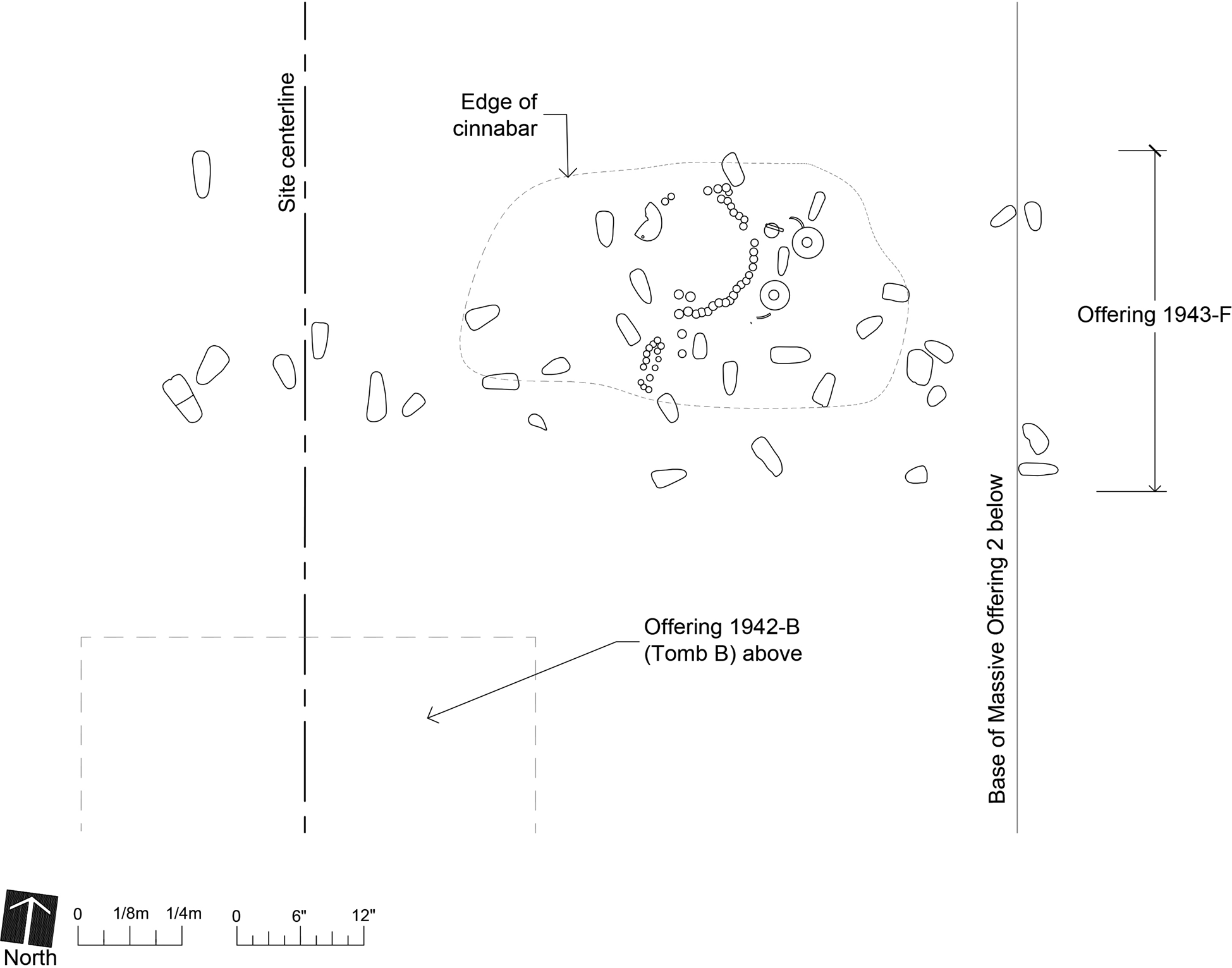
The assemblage yielded 108 objects, including scattered jade celts (as in Tomb C) and personal ornaments; it was later designated Offering 1943-F (Stirling Reference Stirling1943a:Plate IV, lower). Interestingly, it was not centered on the north-south centerline like the four other tombs. No drawing was published of the find, only photographs (Figure 9; Drucker Reference Drucker1952:Plates 13a and 13b; Grove Reference Grove1992:Figure 12). The photographs show how this assemblage was juxtaposed close to the “face” of the Tomb B saurian creature to its south, but over a meter deeper. They reveal two jade earspools with accompanying ear bobs. Just west of them was a discontinuous line formed by 35 beads and another small circle of 14 beads, as if strung jewelry (Wedel Reference Wedel and Drucker1952:63–64). The earspools were placed flat on the same surficial plane as the beads and the scattered celts. Their accompanying “bobs” were laid perpendicular to a presumed body oriented east-west, but one of them is positioned where a head should have been, and a few celts lie flat in what would be the torso area with the beads. Wedel (Reference Wedel and Drucker1952:64) explicitly doubted the status of Tomb E as a burial, calling it instead a “gravelike deposit” because “there were no scraps of bone, tooth enamel, or other items clearly identifiable as remains of a human skeleton.”
Plan of Offering 1943-F (Tomb E) in Mound A-2, drawn from published photographs. Only larger artifacts visible in the photographs are shown.
1955 offerings
Complex A was not excavated again until 1955, when Drucker and Robert Heizer carried out an ambitious program of trenches and area excavations there and in adjacent Complex C (the great earthen pyramid). They did not encounter any funerary features on par with the stone-embellished Tombs A, B, C, and E. They determined, however, that the five tombs excavated in 1942–1943 occurred in the fourth and last of Complex A's major construction phases, which was stratigraphically distinguished by a layer of red or orange-red clay deposited throughout the complex (Drucker et al. Reference Drucker, Heizer and Squier1959:126; Drucker and Heizer Reference Drucker and Heizer1965:48). Furthermore, they recovered several features (among the various “Offerings”) with similarities to Tombs D and E; namely, a layer of red cinnabar with jade ornaments arranged as if on a single corpse, along with other artifacts, but lacking any stone construction or human remains. Significantly, these features were in strata dating to earlier construction phases. They were also in a different location: low clay platforms within the walled Ceremonial Court (Feature A-1) situated between Mounds A-2 and A-3 (Figure 2).
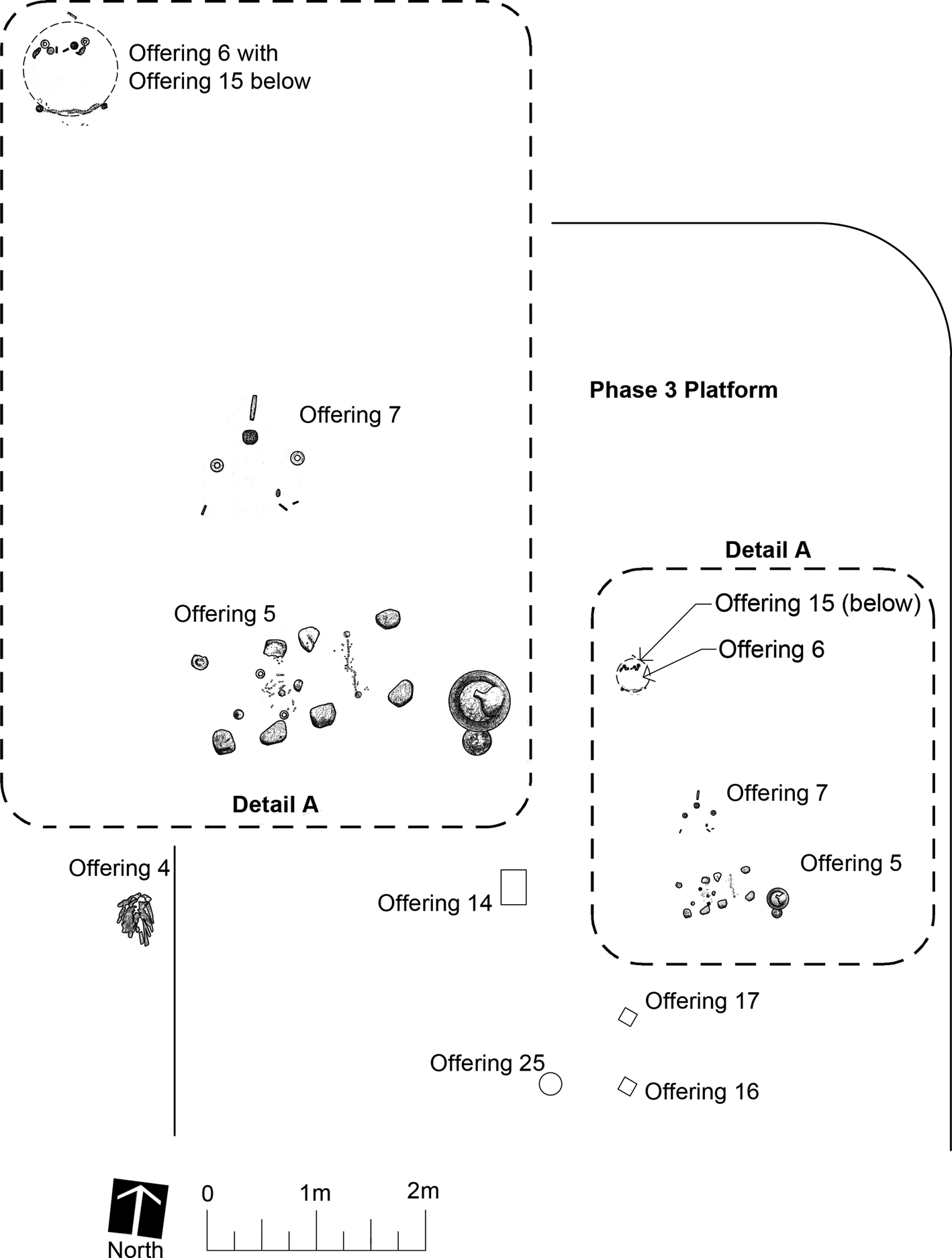
Offering 7 was put in the Northeast Platform possibly in a Phase I stratum, Offering 3 was in the South-Central Platform dating to Phase II, and Offerings 5 and 6 were also in the Northeast Platform but during Phase III (Drucker et al. Reference Drucker, Heizer and Squier1959). Offering 3 consisted of a large number of jade and other objects placed in a bed of cinnabar. Unfortunately, their spatial associations were not observed because the deposit was disturbed by a bulldozer used for quickly removing the overburden in this part of the Ceremonial Court (Drucker et al. Reference Drucker, Heizer and Squier1959:146). Offerings 5–7 were notably similar to one another in the placement of artifacts in a bed of cinnabar and the arrangement of jade and other costume elements, as if worn by an intact body. This was especially striking in Offerings 5 and 6, which included earspools and a string of beads forming a belt worn at the waist (Figure 10; Drucker et al. Reference Drucker, Heizer and Squier1959:162–174).
Plan of the northern half of the Northeast Platform in Phase III with close-up views (see Detail A inset, top left) of published drawings of Offerings 5, 6, and 7 in situ, from Drucker et al. (Reference Drucker, Heizer and Squier1959:Figures 41, 44, and 45).
Interpretations: from elite tombs to a royal mortuary precinct
The five tombs, along with the similar features found in 1955, stimulated varied interpretations of La Venta's political and religious life—the power of its kings and the influence of royal mortuary ritual—that continue to impact conventional views of the Olmecs. Stirling (Reference Stirling1943a; Stirling and Stirling Reference Stirling and Stirling1942) had no doubt that these were burials of high-status individuals. He asserted that Tomb B, the sandstone sarcophagus, held a single “personage, doubtless of prominence” (Stirling and Stirling Reference Stirling and Stirling1942:638). As for Tomb C, Stirling (Reference Stirling1943a:323) opined that its single “occupant [was] undoubtedly a chieftain or priest of highest rank.” The “rich offerings of jade and other materials” convinced him that all these burials were of “important personages” (Stirling Reference Stirling and Oehser1975:306), a less specific identification than his earlier pronouncement that they were “rich and probably powerful rulers” (Stirling Reference Stirling1955:23). Furthermore, the fact that such highly embellished graves had been found only at La Venta among all the known Olmec sites suggested to him that it was “probably the ceremonial center for the entire Olmec region” (Stirling Reference Stirling and Oehser1975:306).
Heizer, who co-directed the 1955 excavations but was responsible for most of the final field report (letters from Robert F. Heizer to William Coe dated 1/21/1964 and 9/11/1964 [RFHP-NAA]), argued strongly for the critical importance of the tombs in late La Venta politics in that publication (Drucker et al. Reference Drucker, Heizer and Squier1959) and some subsequent articles. He reiterated that the three “great tombs” (A–C) occurred exclusively in final construction Phase IV (Drucker et al. Reference Drucker, Heizer and Squier1959:127; Heizer Reference Heizer1960:200, 1961:53), but averred that Phase IV Tomb D (Offering 1943-L) and earlier grave-like caches found in 1955 (Offerings 5–7) were not actual burials but may “symbolize” burials (Drucker et al. Reference Drucker, Heizer and Squier1959:127).
Dating the major tombs to Phase IV was crucial to Heizer's interpretation of La Venta's downfall. He saw them as evidence of increasing “rigorous and autocratic control of the general population than during Phases I to III” (Drucker et al. Reference Drucker, Heizer and Squier1959:127), indicative of the late development of “class differences in the form of burials of high priests” (Heizer Reference Heizer1961:54). He hypothesized that this “highly differentiated class-structured society…became so top heavy that it broke down because of the inability or unwillingness of the general population to support it” (Drucker et al. Reference Drucker, Heizer and Squier1959:127). The tombs provided essential support for his argument that the growing power exerted by a tiny minority of individuals over the populace created an increasingly unstable situation that ultimately precipitated the demise of La Venta (Heizer Reference Heizer1960:220, Reference Heizer1961:50). As the labor required to make and furnish the tombs purportedly reveal, the rulers “imposed such oppressive demands upon the supporting population that the latter either withdrew its support and forced the abandonment of the ritual center, or actively engaged in a social revolt” (Heizer Reference Heizer1961:53; see also Bernal Reference Bernal, Heyden and Horcasitas1969:111; Heizer Reference Heizer1960:220). Utilizing different data, Clark (Reference Clark, Traxler and Sharer2016:142) similarly suggested that Tomb A is evidence for decline at La Venta, because he believes it was constructed of stone materials taken from elsewhere in Complex A, demonstrating an inability of La Venta's last rulers to import new materials.
Importantly, the 1959 multiauthored report on the 1955 La Venta excavations contained contrary statements about the tombs: Drucker (Drucker et al. Reference Drucker, Heizer and Squier1959:162, 169, 171) insisted within the portion he wrote that these were not burials at all, except for Tomb A, and Heizer (Reference Heizer1959:127) opined that the Phase IV tomb burials indicated increasing autocratic control by rulers that may have led to a societal collapse. The mishandling of the “burial” data was part of a brutal critique of the 1959 report by Coe and Stuckenrath (Reference Coe and Stuckenrath1964). They chided the reference to “rich tombs” given the absence of human remains and were unconvinced that even “Tomb” A housed “bundle burials” or “bundles” more generally, as reported by Drucker in 1952 (Coe and Stuckenrath Reference Coe and Stuckenrath1964:23). They believed that the few osseous remains found in Tomb A were placed there for some symbolic value, just like the artifacts, as was the case for some Maya caches, rather than “the rotted residue…of two funereally buried individuals” (Coe and Stuckenrath Reference Coe and Stuckenrath1964:23).
In their joint response to this attack the following year, Drucker and Heizer (Reference Drucker and Heizer1965:56, emphasis in original) reiterated that “no, and we repeat no, primary interments” were found with the offerings, and human skeletal material was recovered only in Tomb A as a secondary burial. “The two lots of human bones in question were obviously remnants collected and redeposited after some cleaning process. They were very incomplete, and consisted mainly of long bones, ribs, and the like, arranged compactly with their long axes parallel, manifestly having been tied or packaged for convenience in handling” (Drucker and Heizer Reference Drucker and Heizer1965:57). This had been Drucker's position since at least 1952 (and see Drucker et al. Reference Drucker, Heizer and Squier1959:169). In a brief 1975 report on the 1942 excavations, Drucker (Reference Drucker and Oehser1975:103) further elaborated on the condition of the Tomb A bones: “The bone was too fragmentary and too badly decomposed by long exposure to soil acids for measurements. No skulls, or skull parts, vertebrae, pelvises, or hand and foot bones, could be recognized among the osseous remains. A small lot of human tooth caps, apparently juvenile (deciduous teeth with very slight wear), were found near one of the bundles.” By that time, he had “reconsidered” that these curated bundles of long bones were more likely “parts of the offering” (Drucker Reference Drucker and Oehser1975:104), as Coe and Stuckenrath (Reference Coe and Stuckenrath1964:23) had earlier suggested.
Nevertheless, despite that 1960s debate, admittedly within a lesser known publication, most Olmec scholars have accepted the original 1940s interpretation that Complex A housed the tombs of La Venta's, and by extension the Olmecs’, highest-status individuals (e.g., Bernal Reference Bernal, Heyden and Horcasitas1969:115; Clark Reference Clark, Traxler and Sharer2016:135; Coe Reference Coe1968:66; Diehl Reference Diehl and Benson1981:78, Reference Diehl2004:70; González Lauck Reference González Lauck, Benson and de la Fuente1996:76–78; Grove Reference Grove, Grove and Joyce1999:265–267; Lowe Reference Lowe1998:71; Luckert Reference Luckert1976:113; Pool Reference Pool2007:164, 177; Reilly Reference Reilly and Fields1994, Reference Reilly and Guthrie1995:35, Reference Reilly and Kowalski1999:29, 33, Reference Reilly and Stone2002:63, Reference Reilly, Berrin and Fields2010:52) or, at least, that they are probably burials (Grove Reference Grove1984:126; Joyce Reference Joyce2000a:44; cf. Gillespie Reference Gillespie, Mills and Walker2008; Grove Reference Grove2014:48; Merry de Morales Reference Merry de Morales and Grove1987:111). In re-examining the totality of the evidence, Colman (Reference Colman2010:124ff) identified 10 burials based on the presence of earspools or other jewelry placed as if on a body, and secondarily on the basis of associated cinnabar, a stone container, or a pit. Tomb A stands out for its (barely) preserved human remains, but the conventional wisdom is that it was built to house two or possibly three juveniles, children, or infants (Clark Reference Clark, Traxler and Sharer2016:136; Colman Reference Colman2010:Table 8; Diehl Reference Diehl1990:59, Reference Diehl2004:70; González Lauck Reference González Lauck, Benson and de la Fuente1996:76; Pool Reference Pool2007:164; Soustelle Reference Soustelle1979:50), possibly even young “princes” (Coe Reference Coe1968:66).
By extension, Diehl (Reference Diehl1990:60) considered the figurines recovered from Tomb A to be therefore “funerary” in purpose. Reilly (Reference Reilly and Kowalski1999:32) further suggested that all of Complex A “functioned as a mortuary complex for the interment of La Venta's elite dead.” Contra Heizer (in Drucker et al. Reference Drucker, Heizer and Squier1959:127), Reilly interpreted the 1955 Offerings 5–7 as burials of high-status individuals predating the major tombs of Phase IV (see also Clark Reference Clark, Traxler and Sharer2016; Clark and Colman Reference Clark and Colman2014; Colman Reference Colman2010). This would indicate a continuity of mortuary ritual that began in Phase I, with Mound A-2 clearly housing the remains of a late paramount ruler (Reilly Reference Reilly and Kowalski1999:33). Clark (Reference Clark, Traxler and Sharer2016:137), however, called attention to the great size and impressive inventory of grave goods in Tomb C in Mound A-3 as “the best candidate for a ruler.”
Following Reilly (Reference Reilly and Kowalski1999), Diehl (Reference Diehl2004:77) conjectured that Mound A-2 was a “royal burial mound surrounding the Tomb B sarcophagus, final resting place for a true Olmec king.” The walled Ceremonial Court to its immediate south thus became a “secluded retreat where La Venta's royalty gathered to commune with their deceased and deified ancestors” (Diehl Reference Diehl2004:67). In his interpretation, it was a stage setting for ancestral rituals that were essential to maintaining political power at La Venta within a dynasty of shaman-kings. Diehl (Reference Diehl2004:64) further mused that the founder of a La Venta dynasty may have been interred in the earthen pyramid (Complex C) that forms the southern boundary of Complex A.
These various scenarios demonstrate how important the royal tombs have become to interpreting ritual and power among La Venta's highest elites, providing at least “a minimal view of revered rulers of this polity” (Clark Reference Clark, Traxler and Sharer2016:138), although Clark (Reference Clark, Traxler and Sharer2016:135) cautioned that the best evidence for kings consists of their depictions on stone monuments. Furthermore, the common assessment that these structures form the resting places of a series of singular rulers–not just of possibly coeval elite individuals–implies a significant evolution of centralized political organization, possibly dynastic kings, at late La Venta, ostensibly predating that development among the Maya. That aside, the La Venta burials developed a singular importance in Olmec archaeology for a simpler reason noted by Stirling (Reference Stirling1955:23, 1975:306): human burials were lacking at other Olmec centers. Cyphers (Reference Cyphers, Traxler and Sharer2016:95–96) reported a few incidents of human remains at Early Formative San Lorenzo and its environs from contexts suggesting human sacrifice. Thus, information on primary human burials or standard funeral practices among the Olmecs outside of La Venta is otherwise still lacking.
Tomb controversies
Two specific controversies are more thoroughly reviewed in this section. The first is whether the tombs are indeed the final resting places of deceased individuals arrayed in their fine regalia. Taphonomic evidence is highlighted in a discussion that may seem belabored beyond what is necessary; however, most arguments about these tombs have centered on issues of preservation. The second is whether these features constitute evidence for a series of successive ruling lords late in La Venta's history. Stratigraphic data are presented to resolve this issue, including reconstructing the sequence of actions during Phase IV that created Tombs A, B, and E in Mound A-2.
Are the tombs really tombs?
As the feature descriptions compiled by their excavators evince, all but one of the 1940s tombs and all of the 1955 “grave-like deposits” lacked an important characteristic of burials: human remains. Not only were the putative primary interments missing, but also possible sacrificial victims or retainers in the larger tombs, such as Tomb C (noted by Clark [2016:138]). The lone exception was the fragile bundle burials of Tomb A. The general absence of human remains at La Venta became another unresolved disagreement between Stirling and Drucker. Stirling (Reference Stirling1943a; Stirling and Stirling Reference Stirling and Stirling1942:638; Stirling letter to Heizer dated 7/26/1965 [RFHP-NAA]) continued to insist that the osseous material in Tombs B-E had disintegrated due to water action and the acidic tropical clays. Drucker (Reference Drucker and Oehser1975:104; Drucker and Heizer Reference Drucker and Heizer1965:56–57; Drucker et al. Reference Drucker, Heizer and Squier1959:162), on the other hand, reiterated his equally strong opinion that none of these features was proven to be a primary burial. The only other 1940s excavator, Wedel (Reference Wedel and Drucker1952:64, 71, 73), took a middle position on the three tombs he investigated in 1943. He concluded that, due to the lack of even faint traces of bone or tooth enamel, “I am unable to state positively, therefore, that these were actually burials, although the impression that they were is a strong one” (Wedel Reference Wedel and Drucker1952:64).
Most commentators on La Venta have taken the side of Stirling, assessing the absence of bone and teeth as a taphonomic issue due to preservation conditions (e.g., Bernal Reference Bernal, Heyden and Horcasitas1969:42; Clark Reference Clark, Traxler and Sharer2016:135; Clark and Colman Reference Clark and Colman2014:17; Coe Reference Coe1968:66; Colman Reference Colman2010:117; Diehl Reference Diehl and Benson1981:78, Reference Diehl2004:70–71; Pool Reference Pool2007:64). Drucker (Drucker and Heizer Reference Drucker and Heizer1965:57), however, pointedly observed that, from his prior experiences in Gulf Coast archaeology, bone never completely disintegrated to the point of invisibility, and tooth caps are “practically indestructible.” Drucker also had recorded the erstwhile presence of disintegrated organic offerings in the Northwest Platform, which was riddled by many pits that contained no surviving artifacts (Catalog of Offerings, Box 3 Alpha [RFHP-NAA]). Stirling (letter to Heizer dated 7/26/1965 [RFHP-NAA]) nevertheless countered that his own experience excavating graves in Panama proved the opposite–that bones and even teeth could be completely absent from what were otherwise typical graves.
Drucker has subsequently been faulted for treating absent evidence as “equivalent to negative evidence” (Colman Reference Colman2010:122). Stirling's (Stirling letter to Heizer dated 7/26/1965 [RFHP-NAA]) argument was that, in humid climates, when personal adornments are found in a position as if worn by a body, it is “more reasonable” to assume that a body had been present rather than absent. This same wording was independently echoed by Pool (Reference Pool2007:177): the “most reasonable interpretation” of Tomb A, Tomb B, and the similar features with precious jade ornaments was that they were “elite tombs and burials.” Given the environmental conditions that impeded the preservation of bone, Colman (Reference Colman2010:117, 124, 127) assumed that its absence was not sufficient to negate the possibility of a burial. She thus inferred that the presence of jewelry in spatial association as if on a body was sufficient, even “compelling” evidence that a body had been present (see also Clark and Colman Reference Clark and Colman2014:17; Clark Reference Clark, Traxler and Sharer2016:135–136).
In sum, the majority opinion is that bones and teeth could not survive over millennia in humid environments and acidic soils. Nevertheless, since those original conclusions were reached, human bone has been excavated in and around Early Formative San Lorenzo (Cyphers Reference Cyphers, Traxler and Sharer2016:95–96), and excavations of habitations on the margins of La Venta revealed a plethora of animal bones (González Lauck Reference González Lauck, Benson and de la Fuente1996:80). Thus, a tropical climate per se cannot be the cause for the absence of osseous material. As some have taken pains to note, in addition to bundled human long bones, Tomb A also contained a separate cluster of juvenile deciduous tooth caps, a shark's tooth, and six stingray tails (Bernal Reference Bernal, Heyden and Horcasitas1969:42; Colman Reference Colman2010:117; Drucker Reference Drucker1952:22–26; Stirling and Stirling Reference Stirling and Stirling1942:641–642; Stirling letter to Heizer dated 7/26/1965 [RFHP-NAA]). There was also the “burned human skullcap” found by Stirling and Stirling (Reference Stirling and Stirling1942:641) in Tomb A, rarely mentioned again (Table 1; e.g., Colman Reference Colman2010:117). Furthermore, throughout the red cinnabar layer of Tomb A, according to Stirling and Stirling (Reference Stirling and Stirling1942:642), there were “copious unrestorable traces of organic material”—unrestorable, but still evident. Given that the fill of Tomb A was the same red clay that surrounded the putative corpses of Tombs B–E, it is difficult to justify some preservation of organic remains, including teeth, in Tomb A and not in the other presumed graves.
Some may suggest that the controversy cannot be resolved without experimental tests on the anthropogenic matrices in Complex A, something impossible to carry out now. Yet, despite the reasonableness of the default presumption of decay, the taphonomic argument has another facet that would contradict it, one that has been generally disregarded except by the archaeologists who excavated the finds. The disintegration of corpses leaves its own traces in the archaeological record. Stirling's original assumption was that bodies were buried adorned with non-perishable items; the artifacts are the principal evidence for the very existence of human burials at La Venta. Once laid out, the bodies were covered with clay. If all that were the case, one would expect to find the ornaments out of their original positions due to decomposition processes. Drucker pointed out that strung beads would become misaligned; earspools would be askew, their pendants resting at odd angles (Drucker et al. Reference Drucker, Heizer and Squier1959:162; Drucker Reference Drucker and Oehser1975:104; Grove Reference Grove2014:48). This is what one finds when excavating intact skeletons wearing such items. For example, compare the disarray of beads and other ornaments on preserved Middle Formative elite burials, such as Burial 6 at Chiapa de Corzo, Chiapas (Clark Reference Clark, Traxler and Sharer2016:Figure 5.15) and Burial 40 at Chalcatzingo, Morelos (Merry de Morales Reference Merry de Morales and Grove1987:Figure 8.4).
The soil packed around the body should have kept the objects somewhat close to their original locations, but that would mean, in terms of micro-stratigraphy, that they should be found at different vertical levels; for example, a forehead maskette higher than the earspools on a supine body. As noted in the feature descriptions above, at La Venta the earspools always lay flat on a single plane, their pendants carefully arranged, and presumably strung beads showed little sign of disarrangement, “which obviously would not have been the case had it been laid across a body” (Drucker et al. Reference Drucker, Heizer and Squier1959:164). Drucker (Drucker et al. Reference Drucker, Heizer and Squier1959:4; letter from Heizer to William Coe dated 9/11/1964 [RFHP-NAA]) made these observations in the section of the 1959 report on the offerings, which he authored. Earlier, Wedel (Reference Wedel and Drucker1952:71), who carefully mapped Tomb C (Figure 7; Wedel Reference Wedel and Drucker1952:Figure 22), observed that all of the objects lay “just above the floor slabs” on a single horizontal plane (see also Grove Reference Grove2014:48). Descriptions, drawings, and photographs of the three intact 1955 offerings with costume ornaments in the 1959 report similarly indicate that the artifacts were positioned at the same horizontal level (Offerings 5–7 [Drucker et al. Reference Drucker, Heizer and Squier1959:Figures 41, 44, plate 38, and 45]). While there is no drawing or known photograph of all the artifacts in situ in Tombs A and B, photographs reveal the Tomb E artifacts were similarly arrayed (Drucker Reference Drucker1952:Plates 13a and 13b; Grove Reference Grove1992:Figure 12). This is compelling positive (not negative) archaeological evidence of what was absent in these features: a decaying corpse.
Do These Deposits Represent a Sequence of Individual Leaders?
The other major controversy follows from the first but has received far less attention. The majority opinion has been that Complex A contained the primary or secondary burials of elite individuals interred soon after death wearing their jade ornaments. At least some are believed to be the graves of actual ruling paramounts, secular or religious leaders who succeeded each other over a period of decades (Heizer Reference Heizer1961:53), the last royal dynasts at La Venta (Clark Reference Clark, Traxler and Sharer2016:123, 136–138). The assignment by the 1955 project of the five tombs to Phase IV, while similar but simpler features date to earlier phases, lent support to the thesis that the power of the rulers, as assessed by mortuary display, increased over time at La Venta. The logical conclusion is that the most powerful kings were entombed in sequence but in unique ways during the last construction phase of Complex A, after which La Venta was presumably abandoned. Significantly, some archaeologists draw on stratigraphic data to support this conclusion, but others disagree, creating another controversy.
Unfortunately, there are many misconceptions regarding the relative stratigraphic positioning of the Complex A layers, structures, and features, not least because the published profile drawings (Drucker Reference Drucker1952; Drucker et al. Reference Drucker, Heizer and Squier1959) have shortcomings and some outright errors (Colman Reference Colman2010; Gillespie Reference Gillespie, Mills and Walker2008, Reference Gillespie2011; Gillespie and Volk Reference Gillespie and Volk2014). Some misreadings have tended to reinforce the interpretation of a mortuary function for Complex A; e.g., statements that Mound A-2 was erected in order to cover Tomb A (Bernal Reference Bernal, Heyden and Horcasitas1969:38; Diehl Reference Diehl1990:59; Reilly Reference Reilly, Berrin and Fields2010:110), and that Mound A-3 was intended to cover Tomb C, despite both mounds’ initiation much earlier in Phase I (Drucker et al. Reference Drucker, Heizer and Squier1959:124).
The defining criterion of the Phase IV construction episode of Complex A is the deposition of the “red clay cap” on all the structures (Drucker et al. Reference Drucker, Heizer and Squier1959:126). It is described as a local clay, red or orange-red, free of topsoil and inclusions except for “crumbs of pottery”–in short, a prepared artificial fill (Drucker Reference Drucker1952:28). Additional distinguishing features of this phase's deposits are the first known uses of imported sandstone, limestone, and basalt in natural columnar form (Drucker et al. Reference Drucker, Heizer and Squier1959:126). In addition to its homogeneity and ubiquity, the upper surface of the red clay layer was notably eroded, indicating that the Complex A stewards had ceased their centuries-long maintenance of the ceremonial precinct, and the entire complex was naturally covered with drift sand (Drucker et al. Reference Drucker, Heizer and Squier1959:25).
The relationship of the red clay cap, which is something of a misnomer, to the tombs has been variously interpreted. A few Olmec archaeologists (Diehl Reference Diehl2004:69; Reilly Reference Reilly and Fields1994:131) considered the red clay deposit as a termination event—a deliberate, pre-abandonment covering to close off the entire area. Others have suggested that the red clay was a layer subsequently added over the earlier tombs. For example, Lowe's (Reference Lowe, Sharer and Grove1989:34, Figure 4.1a) perspective drawing of Mound A-2 with Tombs A and B positioned as free-standing structures on top is captioned as “prior to placement of the final red clay cap on Complex A.” Clark (Reference Clark, Traxler and Sharer2016:136) similarly described Tombs A and B as placed atop Mound A-2, after which “another construction layer was added to the mound to cover both tombs.” Nevertheless, stratigraphic evidence reveals that the tombs, stone sculptures, basalt columns, and other Phase IV elements were embedded in the red clay, which facilitated their erection (Drucker et al. Reference Drucker, Heizer and Squier1959:25). As Coe and Stuckenrath (Reference Coe and Stuckenrath1964:3) remarked, Phase IV was a “multi-faceted climax” of indeterminate length.
Not only do the five tombs of Complex A date to the same construction phase, the three on Mound A-2 (A, B, and E) came together in coordinated fashion as part of a single “unit of construction” (Drucker Reference Drucker1952:27) that also included Massive Offering No. 2 below them (Drucker et al. Reference Drucker, Heizer and Squier1959:49); this point has been reiterated by Reilly (Reference Reilly and Fields1994:128, Reference Reilly and Kowalski1999) and Colman (Reference Colman2010:191–212). They cannot, therefore, be vestiges of primary burials of a series of paramount rulers who reigned and died over years or decades, even as they may have been intended to evoke or commemorate the singular existences of certain historical individuals. The next section lays out the stratigraphic information for these coordinated efforts on Mound A-2 in further detail. Although the two Mound A-3 “tombs” (C and D) were also constructed during Phase IV and enveloped in the red clay, they cannot otherwise be easily linked stratigraphically to the Mound A-2 features and so are not further considered here.
Correlating the Mound A-2 “tombs” and caches as a single construction episode
Here we describe the Phase IV modifications to Mound A-2, utilizing an experiential approach to hypothesize a series of actions engaged in by builders, akin to writing the mound's “biography.” This method is similar to other attempts to link the various features to one another thematically or in sequence (e.g., Colman Reference Colman2010:191–212; Reilly Reference Reilly and Fields1994:130) but provides more detailed information. Our reconstruction is aided by computer-assisted corrections to, and visualizations of, the original field data housed in the National Anthropological Archives, supplemented with photographs from the 1942–1943 excavations at the National Geographic Society in Washington, DC (Gillespie and Volk Reference Gillespie and Volk2014). Our “map” of Complex A is a single Auto-CAD file, created with the original measurements in the Imperial system from the 1955 field season. The profile of Mound A-2 along the centerline (Supplementary Figure 2) is based on the incomplete profile drawing of the west wall of the north-south trench made by Squier in 1955 (“North-South Central Trench–West Wall (Sheet 1)” [RFHP-NAA]), supplemented by test trenches excavated by Heizer's subsequent 1967 field project (Heizer et al. Reference Heizer, Drucker and Graham1968b). Our objective is to demonstrate how the three “tombs” and related features on this platform mound were engineered in tandem with each other, and not erected one at a time at long intervals following the death of an incumbent leader. These actions were not only spatially interconnected; altogether they form a patterned sequence. Some are displayed graphically in a series of profile drawings (Figures 11–15), supplemented by 3D virtual reconstructions of the changes to Mound A-2 (Supplementary Figures 3–17).
First in a series of simplified profile drawings of Mound A-2 indicating the actions undertaken to create Massive Offering 2 in Mound A-2, in sequence from top to bottom. (1) Mound A-2 in its final expansion at the end of Phase III, with Monument 24 (“step-cover”) in position on the northern edge. (2) The excavated pit for Massive Offering 2, with presumed red clay fill brought in as a ramp for the northern edge of the platform. (3) The single layer of rows of serpentine blocks placed in reddish sand into which some jade beads had been scattered. (4) Beginning of the filling of the Massive Offering 2 pit, with Offerings 9 and 11 in position. Silhouette figures are drawn to scale.
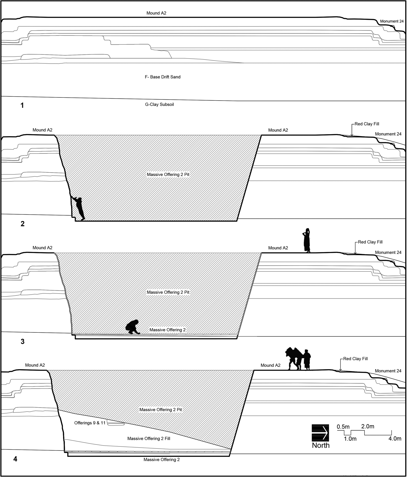
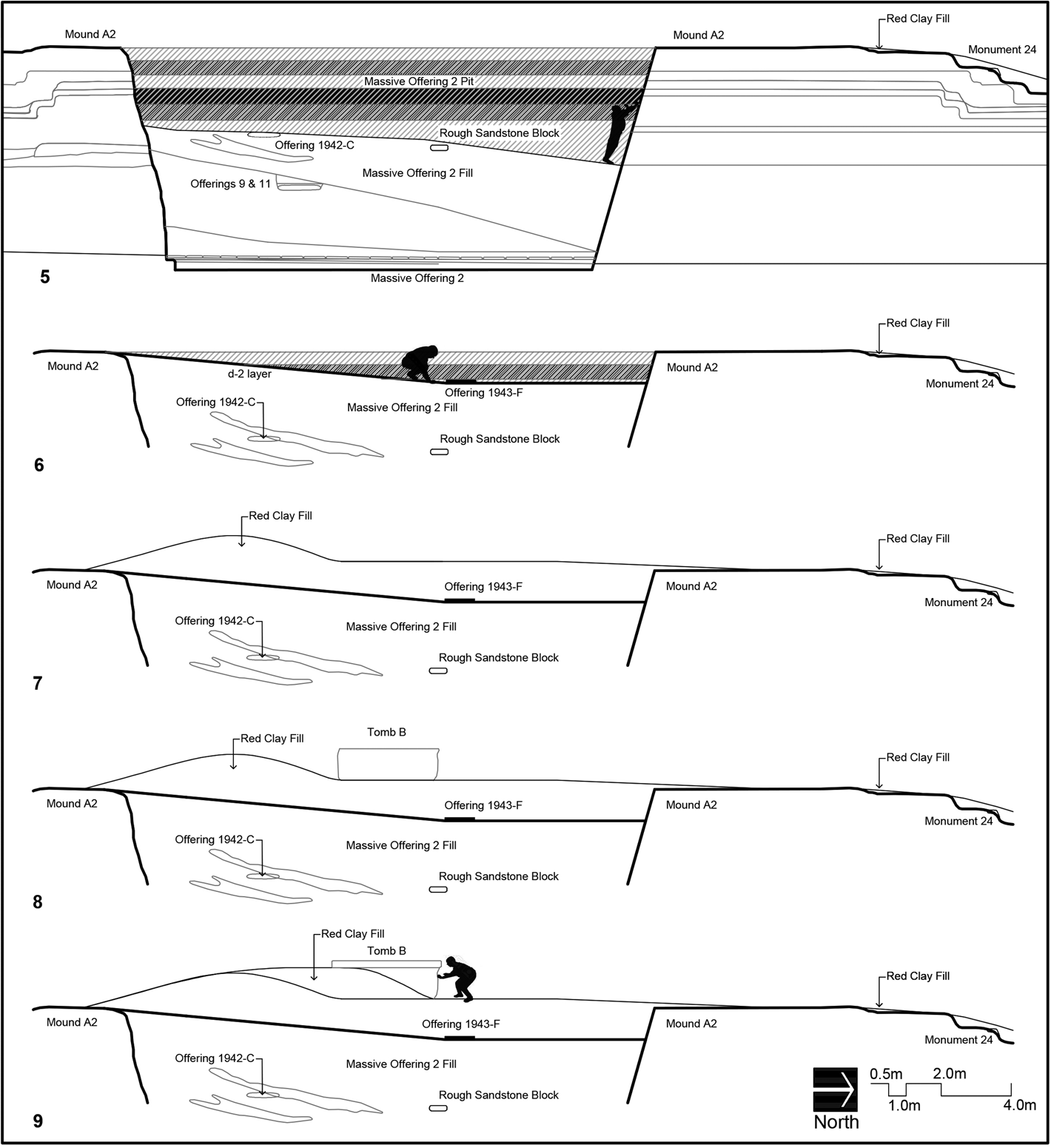
Second in a series of simplified profile drawings indicating the actions undertaken to finish Massive Offering 2, deposit Offering 1943-F, and position Tomb B in place, in sequence from top to bottom. (5) Continued filling of Massive Offering 2 pit, with lenses. Offering 1942-C and the rough sandstone block are in position atop that fill. At least one and possibly more of the sidewalls were painted with bands of color. (6) More fill is placed over Offering 1942-C and the sandstone block, capped by the thin stratum designated d-2, which slopes down from south to north. Offering 1943-F was positioned in vertical space approximate with the d-2 stratum, and horizontally over the rough sandstone block. (7) Red clay fill is brought to the summit to cap Offering 1943-F and cover the Massive Offering fill and stratum d-2. (8) Tomb B is positioned atop the red clay fill over the approximate midpoint of Massive Offering 2. (9) The Tomb B objects (Offering 1942-B) and red clay having been put in the Tomb B box, more red clay is brought in to cover its sides, and the sandstone slab lid is lifted into place to protect the contents.
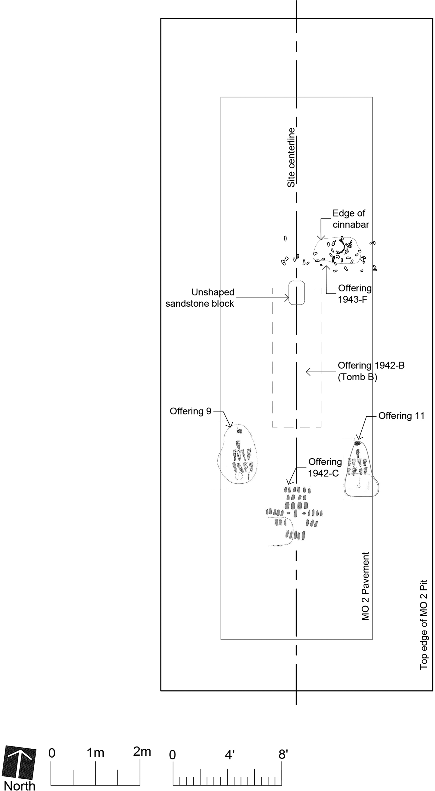
Plan of Mound A-2 with collapsed vertical scale showing the relative positions of the known offering caches associated with Massive Offering 2, ending with 1943-F and 1942-B. The top edges of the Massive Offering 2 pit and the footprints of Tomb B and the Massive Offering 2 serpentine block pavement are shown for reference. Drawings of Offerings 9 and 11 are from Drucker et al. (Reference Drucker, Heizer and Squier1959:Figures 47, 48) and the disturbed 1942-C cache from Drucker (Reference Drucker1952:Figure 10b).
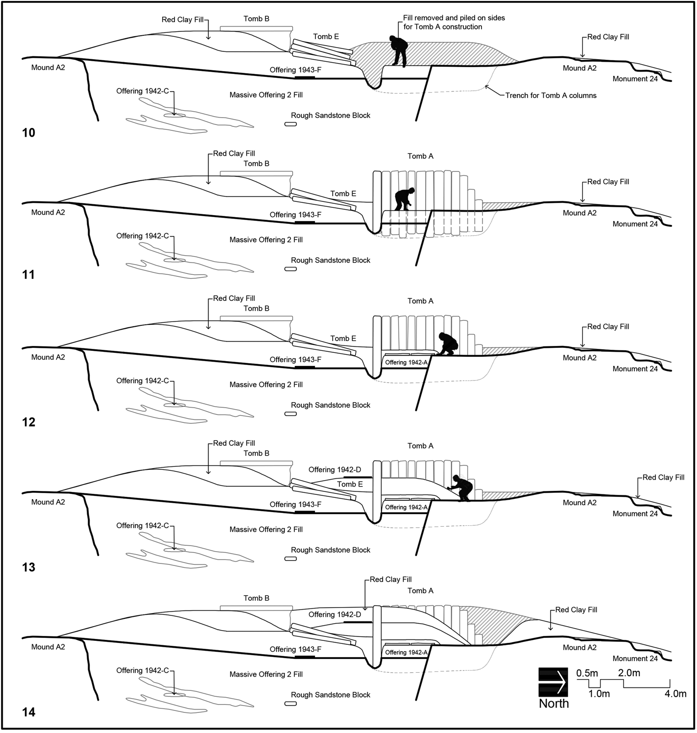
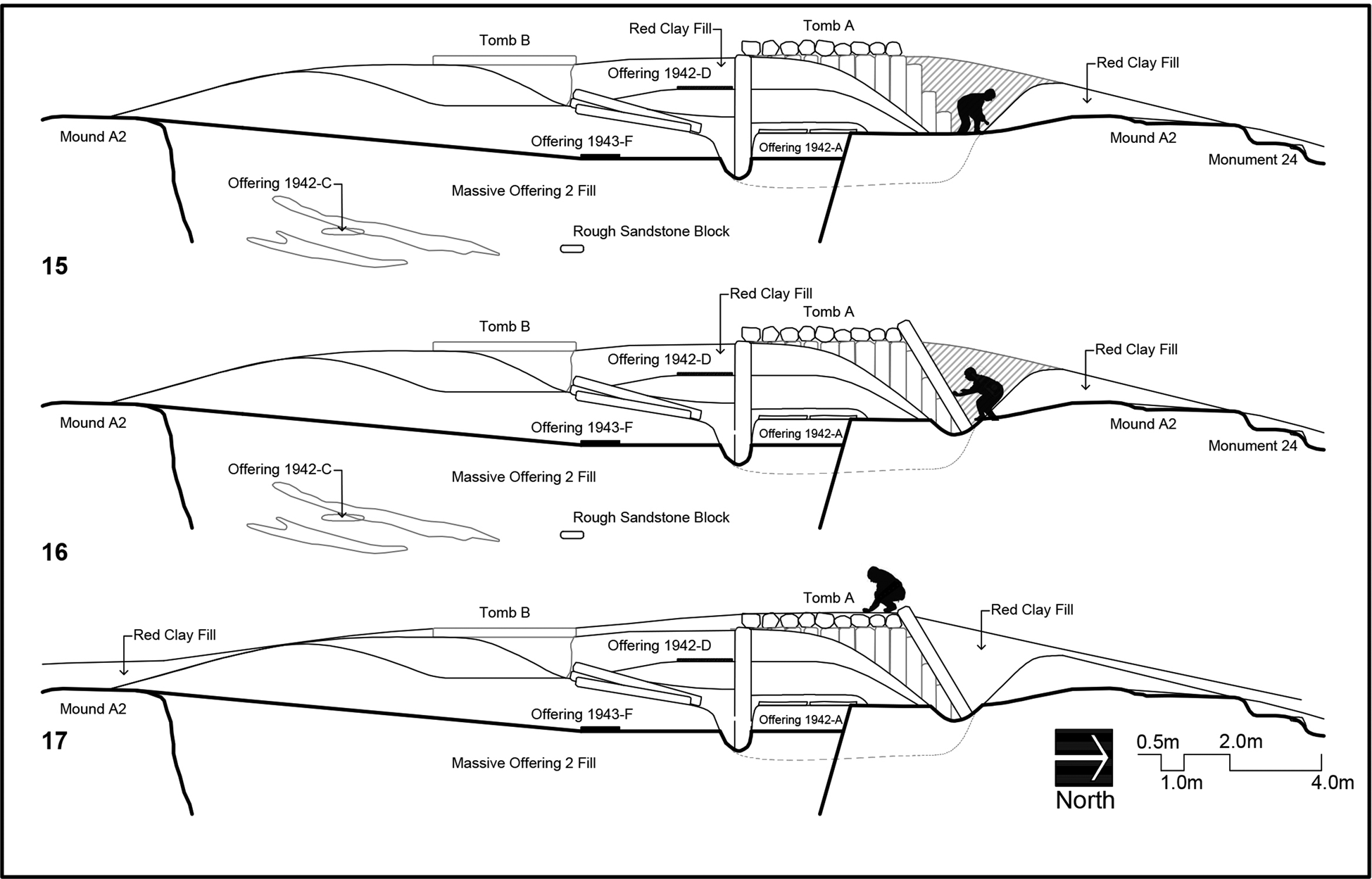
Third in the series of simplified profile drawings indicating the actions undertaken to erect Tomb A, in sequence from top to bottom. (10) Depositing basalt columns immediately south of where Tomb A would be located. Initial trenching has been done to hold the wall columns in place, with excavated fill placed to the east and west of the future location for Tomb A to help shore up the walls. (11) The wall columns are in place for Tomb A on three sides, leaving the north end open. Unused columns are left in place north of Tomb B. (12) The artifacts are laid inside Tomb A atop the limestone flagstones, forming Offering 1942-A. (13) Fill is brought in to cover the 1942-A artifacts, and the Offering 1942-D objects are scattered in red clay fill south of Tomb A. (14) More red clay fill covers Offering 1942-D and up to the top of the basalt column walls of Tomb A, approximately level with the top of Tomb B.
Last in the series of simplified profile drawings indicating the actions undertaken to cap Tombs A and B and all of Mound A-2, in sequence from top to bottom. (15) The roof columns of Tomb A are put in place. (16) The slanting columns forming the “doorway” are leaned against the northernmost roof column. (17) The top surfaces of Tombs A and B are covered with at least a thin layer of red clay. The tips of the slanting “doorway” columns were visible above the ground surface in 1942.
Because there are gaps in the available data, we have made educated guesses as to how the labor was carried out, guided by two assumptions. The first is that the work would have proceeded efficiently, while allowing for changes in design and unintended consequences during the operation. The second is that the overall integrity of Mound A-2—the earliest, tallest, and most important structure in Complex A (Gillespie and Volk Reference Gillespie and Volk2014)—would have been maintained.
With these two operating assumptions, we reason that the workmen ascended the stepped north side of Mound A-2, which at that time (end of Phase III) was approximately 3.35 meters (11 ft) higher than the original ground surface. Here they brought down fill and hauled up clay, stone, and artifacts, possibly with the aid of an earthen ramp. Most efficiently this means that construction materials and cache objects would have been positioned in sequence from south to north, to avoid creating impediments to movements on the summit of the mound (approximately 14.3 meters wide).
We surmise that workers used the north side for access because it was the only one easily accessible. The southern portions of the east and west sides were blocked by the wall of the Ceremonial Court, which was itself enlarged by adding red clay and a line of basalt columns along most of its interior face during Phase IV (the line of columns was never completed; Drucker et al. Reference Drucker, Heizer and Squier1959:26). The south side of Mound A-2 was not only blocked by the Ceremonial Court, but throughout its use-life it was the premier locale for depositing thin layers of clay and sand against upright posts, the last of these being Monument 13, a short basalt column with a relief carving on its upper face (Drucker et al. Reference Drucker, Heizer and Squier1959:40–41). These other façades of Mound A-2 would have been disturbed, if not desanctified, by workers moving up and down. Furthermore, the north side has a rectangular 1.16 m long “step-cover” of imported green gneiss (Monument 24; Drucker et al. Reference Drucker, Heizer and Squier1959: 204). It was positioned on the north-south centerline prior to the placement of the red clay (Drucker et al. Reference Drucker, Heizer and Squier1959:50), likely to protect the protruding edge of the stepped, clay platform mound (Supplementary Figure 3). Its exact position is uncertain, as is the entirety of the north edge of Mound A-2, because the 1955 project never finished drawing the profile of the excavation trench north of Tomb A, an area badly disturbed by construction bulldozing (Drucker et al. Reference Drucker, Heizer and Squier1959:47), and the 1943 trench profile drawings by Wedel were lost (Wedel Reference Wedel and Drucker1952:61).
Massive Offering 2
Leaving aside the complex earlier construction history of Mound A-2 (Phases I-III; Figure 11-1), Phase IV was initiated by digging a large (15.08 × 6.9 m, N-S and E-W, respectively), steep-sided, rectangular pit oriented north-south on the centerline, through the heart of the platform, some 6.32 m deep extending below the anthropogenic layers into the clay subsoil (Figure 11-2 and Supplementary Figure 4). It is possible that the material removed from this pit was used to make a ramp on the north side of the mound for ease of access. The pit was intended, like the four other known massive offerings, to hold rows of prepared serpentine blocks on its bottom surface. Designated Massive Offering 2 (Drucker et al. Reference Drucker, Heizer and Squier1959:128–129), in this case only a single layer of blocks was laid, forming a kind of paved bottom to the pit. These blocks were uniquely positioned atop a ca. 15.2 centimeters (6 in) diminishing to 6.3 cm (2.5 in) fill layer of bright, red, sandy clay into which, at the very least, seven jade beads had been placed (Figure 11-3; Heizer et al. Reference Heizer, Drucker and Graham1968b:8). Heizer surmised from the uneroded steep sides of the pit, which were apparently not shored up, and the absence of signs of erosion in the fill that the excavation and filling of this feature occurred rapidly, during a single dry season (Drucker et al. Reference Drucker, Heizer and Squier1959:42, 129).
Once laid, the serpentine blocks were covered with clay fill, and then a deeper layer of brown sandy fill in which several discrete lenses of “sandy loading layers” were added (Figure 11-4). All these layers and lenses sloped down from south to north, suggesting that the filling operation proceeded from the south end. At a depth of 3.96 m (13 ft) below the Massive Offering 2 pit opening, Offerings 9 and 11 were deposited in shallow pits 1.37 m (4 ft 6 in) west and east, respectively, of the north-south centerline (their vertical position is indicated in Figure 11-4). These are the first known caches put into the pit fill and were discovered in 1955 (Drucker et al. Reference Drucker, Heizer and Squier1959:176–184). They constituted twinned arrangements of one iron-ore mirror with nine jade and serpentine celts in association with red and purple cinnabar and hundreds of jade beads; neither offering has been deemed a potential burial. These caches were part of a change in the filling process; above them, a different matrix was used to fill the pit. The 1942 excavations reached this latter matrix, uncovering a cruciform arrangement of 37 jade celts (Offering 1942-C) on the centerline at a depth of 2.38 m (7 ft 10 in; Drucker Reference Drucker1952:27, Figure 10b). Perhaps when or after this cache was deposited, we suggest that workers stood on the fill to put a thin layer of yellowish, sandy-clay “plaster” on the surface of the upper portion of the pit wall, at least on its southern side (not discovered until 1967). On this prepared surface were bands of paint in alternating colored stripes of purplish-red and black or deep brownish-black (Figure 12-5; Heizer et al. Reference Heizer, Drucker and Graham1968b:10–11, Figure 8). Additional fill with discrete lenses was then added, again mapped as sloping down from south to north. A rough unworked sandstone block, similar in material to the Tomb B coffer, was encountered in 1955 near the horizontal and vertical midpoint of the pit (Drucker et al. Reference Drucker, Heizer and Squier1959:49).
Importantly, the pit fill, having reached the Phase III summit of Mound A-2 on the south edge, was topped by a distinctive thin, gray-tan, sandy clay layer, also sloping down to the north at the same general angle (Figure 12-6; stratum d-2 in Drucker et al. [Reference Drucker, Heizer and Squier1959:Figure 12]). This layer forms a discontinuity between the fill of the pit and the subsequent red clay matrix that enveloped the tombs. It was apparently continuous across the top of the fill and may have been disturbed by the placement of Monuments 6 and 7 (Tombs B and A; Drucker et al. Reference Drucker, Heizer and Squier1959:43, 49). Virtually all the anthropogenic building fill above stratum d-2 is the red clay that covered Complex A in Phase IV.
Offering 1943-F
Projecting stratum d-2 at its extant sloping angle reveals that it intersects with the placement of Offering 1943-F, the “Tomb E” assemblage of artifacts with cinnabar. We therefore interpret the placing of this cache, which is off the centerline, as an action to ritually terminate the filling and capping of the Massive Offering pit (Figure 12-6 and Supplementary Figure 5). It was the fourth known cache deposited near the center of the mound, preceded by Offerings 9 and 11 and 1942-C, but it is located farther north, above the rough sandstone block 1.93 m (6 ft 4 in) below, near the midpoint of the Massive Offering pit (Figure 13). The 1943-F artifacts were then covered with the red clay fill (Figure 12-7). While some have suggested that Offering 1943-F was placed in a pit dug down through the red clay after Tomb B was positioned, and only then covered with horizontal basalt columns (Clark Reference Clark, Traxler and Sharer2016:136–137; Colman Reference Colman2010:191, Figure 117), there is no evidence of a pit intruding into that matrix or of a different fill material. Furthermore, excavating such a large opening immediately adjacent to Tomb B would likely have caused the heavy sandstone box to subside. As described below, we suggest the 11 basalt columns that lie above Offering 1943-F were positioned later for Tomb A. While the cache was not forgotten, it may be only unintentionally associated with basalt columns as a result of the entirety of activities during this construction phase, and could justifiably be linked with Tomb B and/or Tomb A.
Tomb B
Assuming the workers brought materials up from the north side of the mound, they would most efficiently have placed Tomb B first, rather than Tomb A, as it would have been difficult to move the large, heavy sandstone box and lid around that structure on the narrow summit of the mound. Tomb B was positioned on a thick layer of the red clay fill, presumably after its relief design was carved into three sides, so that clay had to have been brought up first (Figure 12-8 and Supplementary Figure 6). This box lies directly atop the midpoint of the Massive Offering, though not at the midpoint of Mound A-2. Thus, among the Mound A-2 tombs it is believed to be most directly associated with that feature (Supplementary Figure 7; Reilly Reference Reilly and Fields1994:128).
The base of Tomb B is approximately 0.59 meters (1 ft 11.5 in) higher than the projected base of Tomb A's basalt column walls, as shown in the early profile drawing (Drucker Reference Drucker1952:Figure 9). In the later published profile drawing (Drucker et al. Reference Drucker, Heizer and Squier1959:Figure 12), the base of Tomb B was erroneously drawn as sitting atop the d-2 stratum, about level with the bottom of Tomb A. Photographs taken in 1942 show that the tops, not the bottoms, of both structures are approximately aligned inches below the ground surface (Drucker Reference Drucker1952:Plate 1; Stirling and Stirling Reference Stirling and Stirling1942:636). At some point after the sandstone box was in place, the artifacts were laid within it and red clay and sand fill added up to the top (Stirling and Stirling Reference Stirling and Stirling1942:641). Its heavy lid may not have been put in place until more red clay was mounded up on either side of the box, to avoid having to lift it very far off the surface (Figure 12-9 and Supplementary Figure 8). Tomb B was most likely completed and capped before serious work began at Tomb A.
Tomb A
Tomb A, which is far larger and more imposing, may not have been part of an original design plan that focused on Tomb B, and seems to have involved repurposing resources originally designated for elsewhere in Complex A. According to Wedel (Reference Wedel and Drucker1952:65, 78), the 11 basalt columns above Offering 1943-F together with the approximately 38 full-length columns of Tomb A would account for the gaps in the Phase IV basalt columns positioned along the inner east wall of the Ceremonial Court. That wall was never completed (cf. Clark [2016:142], who stated that the columns were “taken from a palisade built several centuries earlier”; all of the columns date to construction Phase IV). The columns of both Tombs E and A were “of the same sort, but the former were smaller in diameter and less regular in cross-section than the latter” (Drucker Reference Drucker1952:27). When encountered in 1942, the columns lying south of Tomb A were all oriented north-south, forming an irregular, east-west grouping that was deeper in the middle than along the edges, with some columns “considerably tilted” (Drucker Reference Drucker1952:27). At that time, they were considered “building material left over after the construction of nearby Tomb A” (Wedel Reference Wedel and Drucker1952:63).
Although this idea was dismissed with the excavation in 1943 of the cache of artifacts below the supine basalt columns and their collective designation as Tomb E, we suggest that the original supposition was more likely correct. The Tomb E columns were among those brought up to the surface of Mound A-2 after Tomb B was positioned, as building material for what would become Tomb A. They may have been rejected for being somewhat inferior in size and shape to the other Tomb A columns, which were carefully selected. The 11 remaining were not subsequently removed, which would have required maneuvering them around Tomb A as it was being erected. Removal may not have been considered necessary given that they were destined to be quickly covered with red clay.
We thus surmise that, after Tomb B was in place and likely after red clay had been put within and around it, workers began bringing up the basalt columns to make Tomb A, stacking many of them destined for that purpose on the sloping red clay fill just north of Tomb B (Figure 14-10 and Supplementary Figure 9). Importantly, Drucker and Heizer (Reference Drucker and Heizer1956; see also Drucker et al. Reference Drucker, Heizer and Squier1959:Plate 9a) discussed how the basalt columns may have been moved based on their own excavation experience. Rather than roll them on the ground, the 1955 La Venta workers utilized the “time-honored system of slinging the weight from poles and getting everybody and his brother to shoulder them” (Drucker and Heizer Reference Drucker and Heizer1956:375, 369). By this means, a single basalt column was suspended with ropes tied to several poles along its length, the poles being perpendicular to the orientation of the column. Placing the poles on their shoulders and heaving upwards, several people could lift and carry the column. In such a manner, the columns could have been individually walked up the north side of Mound A, their orientations running north-south parallel to the mound. Dropped in place in a stack just north of Tomb B, their collective weight may have contributed to their sagging into the fill of Massive Offering 2.
What happened next to raise most of those columns to create the tomb's back (south) and east and west side walls is judged from observations made by Drucker in 1942 and the engineering techniques used elsewhere in Complex A. As noted previously, in Phase IV, upright basalt columns were placed on the interior of a Phase II adobe brick wall encircling much of the Ceremonial Court and also atop the Phase II, adobe-brick, Southeast and Southwest Platforms that form its southern border. In all those cases, trenches were dug into the adobe brick and partially filled with the Phase IV red clay to prop up the columns and hold them in place (profile drawings in Drucker et al. [Reference Drucker, Heizer and Squier1959:Figures 6, 26, 27]).
Atop Mound A-2, there should also have been trenches dug in which to place the columns, which could not stand on their own. Trenches were excavated into the red clay that had been brought up with Tomb B, extending down approximately to the d-2 stratum that topped the Massive Offering fill and north beyond that fill; Tomb A straddles the northern edge of the Massive Offering pit (Figure 14-10 and Supplementary Figure 9). Leaving the area in the center unexcavated contributed to the 30.48 cm (1 ft) clay “platform” that elevated the Tomb A artifacts (Figure 14-11 and Supplementary Figure 10). The basalt columns were positioned presumably from south to north, five to form the back wall and nine each on the east and west sides. Some were positioned deeper than others so that their tops were level. As they were put in place, the red clay removed from the trenches, along with additional red clay brought up for this purpose, was mounded on the east and west exterior walls especially, as “construction aids” to keep the columns from toppling (Drucker Reference Drucker1952:26). The irregular five-sided columns were positioned with care so that their widest sides were on the interior, forming a relatively smooth, gapless surface compared to the exterior façade (Drucker Reference Drucker1952:23; Stirling and Stirling Reference Stirling and Stirling1942:639).
With the south, east, and west walls held in place by the red clay, work could proceed inside. Atop the interior raised area were placed approximately eight pieces of flattish limestone of irregular size and shape (Figure 14-12, refer back to Figure 4). As noted above, the published plan view of these flagstones (Drucker Reference Drucker1952:Figure 10) does not quite match their appearance in the photographs (Drucker Reference Drucker1952:Plate 1; Stirling and Stirling Reference Stirling and Stirling1942:636). According to Stirling (Stirling and Stirling Reference Stirling and Stirling1942:636), the stones were covered with a thin layer of blue clay that was topped by an irregular layer of red cinnabar about 15 centimeters (6 inches) thick. Drucker (Reference Drucker1952:23) remembered it differently: an irregular layer of “olive-brown clay or swamp muck” was topped by two bundle burials coated in red cinnabar paint. One unpublished National Geographic Society photograph by Richard Stewart (#25674-TR) shows several of the Offering 1942-A objects, apparently in situ, atop the bed of clay with part of the limestones exposed below. They consist of a jade seated figure, broken but complete, lying face up (Figurine #2; Drucker Reference Drucker1952:Plates 46 and 47) and, about 15 centimeters away, a standing blue jade figurine, face up (Figurine #3; Drucker Reference Drucker1952:Plates 47 and 48). Near the feet of the standing figurine were three D-shaped pieces of jade in a row and a tubular bead (possibly Drucker Reference Drucker1952:Plate 57A, a). These last four objects were not mentioned by Stirling and Stirling (Reference Stirling and Stirling1942:640) as found with the figurines. The two figurines and three D-shaped pieces were assigned to Drucker's Burial Bundle I near the north edge of the platform, which does conform with Stirling's description of where they were encountered.
With the artifacts and other materials, including organics, in position, the interior of the tomb was filled with red clay “packed…to the roof” (Stirling and Stirling Reference Stirling and Stirling1942:640). More red clay was brought to the summit of the platform mound to further support the exterior walls. When it reached a level approximately halfway up the back (south) wall of Tomb A, a selection of jade objects was “scattered” in the fill adjacent to that chamber within a ca. two meter area: two small earspools, a few beads, and an incomplete serpentine figurine (Figure 14-13 and Supplementary Figure 11; Drucker Reference Drucker1952:27). Drucker (Reference Drucker1952:28) commented that there was no indication of purposeful placement of these objects, and there is no published photograph or drawing of them in situ. Catalogued as Offering 1942-D, this scattering is the last known formal deposit of precious objects as part of the construction unit that began with Massive Offering 2 and the jade beads placed below its serpentine blocks. Offering 1942-D was positioned above the northern portions of the Tomb E basalt columns, but not over the 1943-F cache covered by those columns, which is further south. Conceivably a relationship was made by the stewards in charge of the construction among all these caches and stone constructions in some holistic manner.
Still more red clay was brought in to cover Offering 1942-D between Tombs A and B, up to the top of Tomb A's walls (Figure 14-14 and Supplementary Figure 12). This was necessary to position the horizontal roof columns, which were most likely brought up when needed and laid south to north (Figure 15-15 and Supplementary Figure 13). Once the tomb chamber was filled and the roof columns were laid in place, then the north side, with its graduated columns on the sides and slanted long columns laid against the roof, was finished (Figure 15-16 and Supplementary Figure 14). This “doorway” may not have required a deep trench to hold the columns in place. These columns as well were covered with a thin layer of red clay, part of a general capping operation that continued covering the entire mound (Figure 15-17 and Supplementary Figure 15).
A subsequent action worthy of mention as part of this large operation is the erection of Monument 13 on the centerline at the south foot of Phase IV Mound A-2, uncovered by Stirling and Wedel in 1943 (Supplementary Figure 16). This basalt monument, approximately 80 centimeters tall, is described as a short block or columnar drum (but unlike the columnar basalts of Tomb A) forming a squat, upright post with a smoothed, upper, near-circular surface upon which there is a low-relief carving (Figure 16 and Supplementary Figure 17; Drucker Reference Drucker1952:180–182; de la Fuente Reference de la Fuente1973: 262). The relatively naturalistic profile rendering of a striding, human figure juxtaposed with what looks like a short, vertical column of simple hieroglyphic signs has raised doubt in the minds of some archaeologists and art historians that it originated in the late Middle Formative, still within the Olmec era (Lacadena García-Gallo Reference Lacadena García-Gallo, Uriarte and González Lauck2008:612–614). To them it is stylistically too late, more epi-Olmec (after 400 b.c.) than Olmec (e.g., Berrin and Fields Reference Berrin and Fields2010:242; de la Fuente Reference de la Fuente1973:262–264; Taube Reference Taube2004:45; cf. Soustelle Reference Soustelle1979:52). Wedel (Reference Wedel and Drucker1952:63), however, had no doubt that it was directly associated with Mound A-2. Its irregular broken base was made to fit the slope of the mound, so that the top would be flat. Notably, Monument 13 sits on the red clay but was not covered with this matrix like the rest of Complex A.
Three-dimensional reconstruction of Monument 13 in situ at the southern foot of Mound A-2, above the red clay cap, showing the relief design on the top surface.
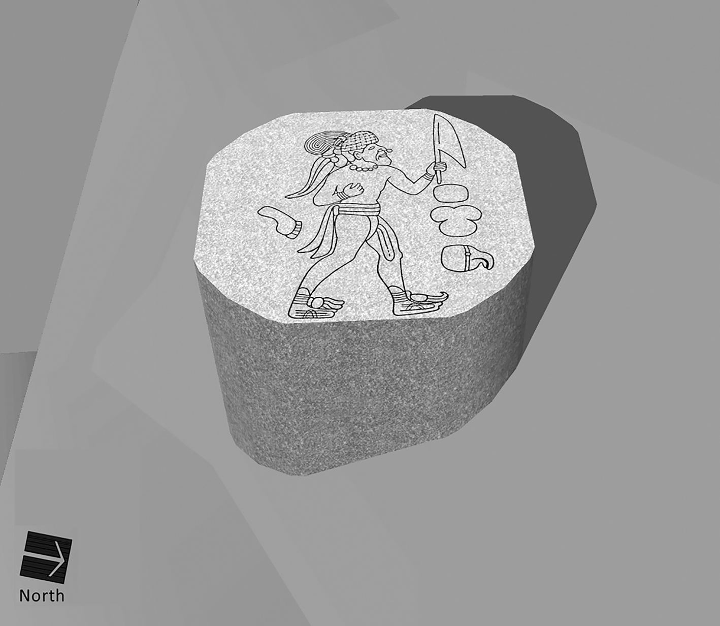
Monument 13 is not an anomaly in its setting. As noted above, the central point of the southern base of Mound A-2 had seen a series of posts or even a line of posts, against which thin layers of colored sandy clays had continually been deposited (Drucker et al. Reference Drucker, Heizer and Squier1959:40–41, Figure 10). Monument 13 was the last of these, likely the largest. On its upper surface, the man walks from south to north (orientation based on in situ National Geographic Society photographs by Richard Stewart in 1943, #33578-TR, 33579-TR). “Facing north” with “head” to the south is how Stirling (Stirling and Stirling Reference Stirling and Stirling1942: 638) described the position of the putative person laid in Tomb B. Apparently, this directional orientation was an axiomatic pattern for Mound A-2 and all of Complex A. Mound A-2 is the tallest structure, the focus of vision and experience among the participants in the rituals conducted within a sacred precinct (the walled Ceremonial Court) that was most likely entered from the south (Gillespie and Volk Reference Gillespie and Volk2014).
Discussion: La Venta's “bodiless burials” and non-absent persons
The long-held “reasonable” explanation that La Venta's “Tombs” A–E were indeed the funerary deposits of elite individuals, even a sequence of kings, does not match the taphonomic and stratigraphic evidence. Two of the three 1940s excavators reached that conclusion at the time, while the third adamantly argued for the other side. This is more than a legitimate disagreement among professionals that could be resolved with, for example, more soil studies. Its significance lies at the heart of archaeological conventions that both move the discipline forward while also introducing interpretive biases.
Why did most subsequent commentators agree that Stirling's position was the “reasonable” explanation? Most obviously they were applying reason in the form of Occam's Razor—accepting the simplest and most parsimonious possibility among alternatives. This explanation also corresponds with disciplinary knowledge and practice, an immediate response to the “incompleteness” or “absence” that haunts archaeology (Lucas Reference Lucas2012:14). On a more pragmatic level, the decay of perishable organics is indisputable in humid tropical environments; hence, the absence of bone was not an impediment to the erstwhile existence of corpses. Furthermore, tombs and other elite burials constitute a well-established category of features, not unexpected within monumental architecture at a major politico-ritual center. Classifying them as such aligns practices carried out at La Venta with those known elsewhere in Middle Formative Mesoamerica (e.g., Joyce Reference Joyce, Richards and Van Buren2000b:71). It also, however, absolves archaeologists from explicitly devising alternative explanations, a necessary precondition for applying Occam's Razor. Indeed, Drucker was faulted for not presenting a different interpretation of these features to buttress his assessment that they were not burials (Colman Reference Colman2010:123); that is, to demonstrate that the simplest explanation was not valid.
A deeper investigation of the reasonableness of this explanation would begin by recognizing that archaeologists “enact knowledge of the world rather than straightforwardly represent it” (Hicks Reference Hicks, Hicks and Beaudry2010:95, emphasis in original). As Hicks (Reference Hicks, Hicks and Beaudry2010:92) further explained, out of events such as fieldwork, grounded in disciplinary traditions, “objects of enquiry emerge as effects rather than prior entities.” The elite burials at Complex A came into being because of established archaeological practice, even as contrary indications were also observed and subsequently discounted in accordance with our conventions.
This is not a minor or pedantic issue. First, the typological category of “burial” has proven inadequate at La Venta and elsewhere. Among the neighboring Maya, for example, burials and caches often cannot be distinguished and are better considered part of a continuum of ritual or dedicatory practices (Becker Reference Becker, Danien and Sharer1992). Second, the burials as burials have always loomed large in conventional understandings of late La Venta and its ultimate fate. In a letter to Heizer dated July 26, 1965, Stirling laid out his reasons for positing actual human burials at La Venta. Notably, he ended with this sentence: “Guess I have belabored this point more than it deserves, but if this is not the case, the mistakes with regard to archeological and historical assumptions could be important” (Correspondence Box 1, RFHP-NAA). A more recent assessment (Colman Reference Colman2010:124) concurs that “the presence or absence of bodies is significant in reconstructing the history of La Venta.” How should we interpret Complex A if these are not real burials and if the Phase IV tombs are virtually contemporaneous? What does this mean for understanding the history of La Venta, and the Olmecs more generally, toward the end of the Middle Formative period?
Bernal (Reference Bernal, Heyden and Horcasitas1969:42) mused that if these features were not burials, then the rationale for their existence was a “mystery,” especially as this “strange custom…was not to be continued in Mesoamerica.” In other words, bodiless tombs would make La Venta stand out as unlike other places. In fact, La Venta Complex A revealed many unusual, unprecedented, exaggerated, and unique practices that could be considered even more enigmatic than a few “grave-like deposits.” The three great mosaic “masks” of polished serpentine blocks (Massive Offerings 1, 4, and 5), buried almost as soon as they were laid out in huge pits, were also considered “mysterious” (e.g., Coe Reference Coe1968:61–62). Given the propensity for the La Venta Olmecs to bury enormous amounts of imported serpentine and jade objects, Drucker and Heizer (Reference Drucker and Heizer1956:367–370) even wondered, only half-jokingly, “Were they mad?”
Yet several patterns among the buried caches were apparent, indicative of repeated intentions and aesthetic practices. Certainly the most dramatic are the five Massive Offerings of many tons of worked serpentine blocks, and an apparent sixth one disturbed by the digging of a drainage ditch north of Complex A (called the North Pavement area; Drucker et al. Reference Drucker, Heizer and Squier1959:233). Dating to construction Phases II–IV, the Massive Offerings indicate a continued practice. As for the small offerings, just after fieldwork ended in May 1955, Drucker (Catalog of Offerings, Box 3 Alpha, RFHP-NAA) recorded his observation of “[two] very obvious special offering patterns.” One was the placement of jade and serpentine celts in a cruciform layout in the clay fill over each of the five Complex A Massive Offerings (Drucker et al. Reference Drucker, Heizer and Squier1959:129). This type of deposit has been found at contemporaneous ceremonial centers in Chiapas and the Maya lowlands (e.g., Clark Reference Clark, Traxler and Sharer2016:151, 165). The other was what he called “earspool-assemblies and beads,” applicable to 1955 Offerings 5–7 and Tombs B–E. In the 1959 report (Drucker et al. Reference Drucker, Heizer and Squier1959:162, 164, 169, 171), he made these arguments more formally, referring to this latter pattern as “pseudoburials” (Drucker et al. Reference Drucker, Heizer and Squier1959:169).
In their critique of the 1959 site report, Coe and Stuckenrath (Reference Coe and Stuckenrath1964:23–25) gave a more definitive classificatory designation to this type of cache, which at the time they considered unique to La Venta: the “substitute” or “surrogate burial.” The type was defined by three criteria: (1) the formal arrangement of beads, earspools and their pendants, and possibly other adornments such as maskettes to replicate their positions as if on a body; (2) the absence of any trace of skeletal material; and (3) the occurrence of artifacts on, under, or within a layer of cinnabar or cinnabar mixed with clay. Coe and Stuckenrath identified eight examples: Offerings 5–7, the offerings of Tombs A–E, and possibly Offering 1942-D found in the clay fill between Tombs A and B (Colman [Reference Colman2010] identified Offering 1942-D as a burial). Offering 1942-D, however, lacks the cinnabar, and its surviving artifacts (two jade earspools, jade beads, and a fragmentary serpentine figurine) appeared to have been scattered in the orange-red clay fill over a two-meter area (Drucker Reference Drucker1952:27–28). Failure to meet criteria 1 and 3 led Coe and Stuckenrath (Reference Coe and Stuckenrath1964:24) to disregard Offering 1942-D within the class of surrogate burials. They also wavered on the Tomb B finds because there was no mention of cinnabar or a special red matrix; nevertheless, they included it because of the imposing sarcophagus itself, and it met criterion (1) according to Stirling.
Colman (Reference Colman2010:Table 8) and Gillespie (Reference Gillespie, Mills and Walker2008:Table 6.2) added Phase II Offering 3, in the South-Central Platform, to this group. Although the positions of the jade and other adornments were not recorded, they did occur in a bed of cinnabar and were covered with a thin layer of bright, yellow clay like some of the Phase III examples (Drucker et al. Reference Drucker, Heizer and Squier1959:146). This brings the total number of surrogate burials excavated in Complex A to nine, counting Tomb A as one occurrence (Table 2). Outside of Complex A was Offering 1940-A, excavated by Stirling. It consisted of 99 jade beads and one amethyst bead situated as if strung as a necklace and two bracelets. This cache was placed in front of Altar 4, south of the great pyramid, on the same level of the floor upon which the altar itself once sat (Stirling Reference Stirling1940, Reference Stirling1943b:55). Although some archaeologists treat Offering 1940-A as another possible non-preserved burial (Clark Reference Clark, Traxler and Sharer2016:135; Clark and Colman Reference Clark and Colman2014:29, n3), there was no recorded red cinnabar or similar colored matrix. Furthermore, Stirling himself did not consider the arrangement of artifacts indicated an absent body. Offering 1940-A, however, is another example of the caching of personal jade ornaments at La Venta (Grove Reference Grove2014:35).
Candidates for “Surrogate Burials” at La Venta Complex A, based on Drucker et al. (Reference Drucker, Heizer and Squier1959:133-191, 218–226, Table 1, Appendix 1) and Drucker and Heizer (Reference Drucker and Heizer1965:59). Criteria are: (1) costume items arranged as if on a body, (2) absence of any trace of skeletal material, and (3) associated cinnabar.
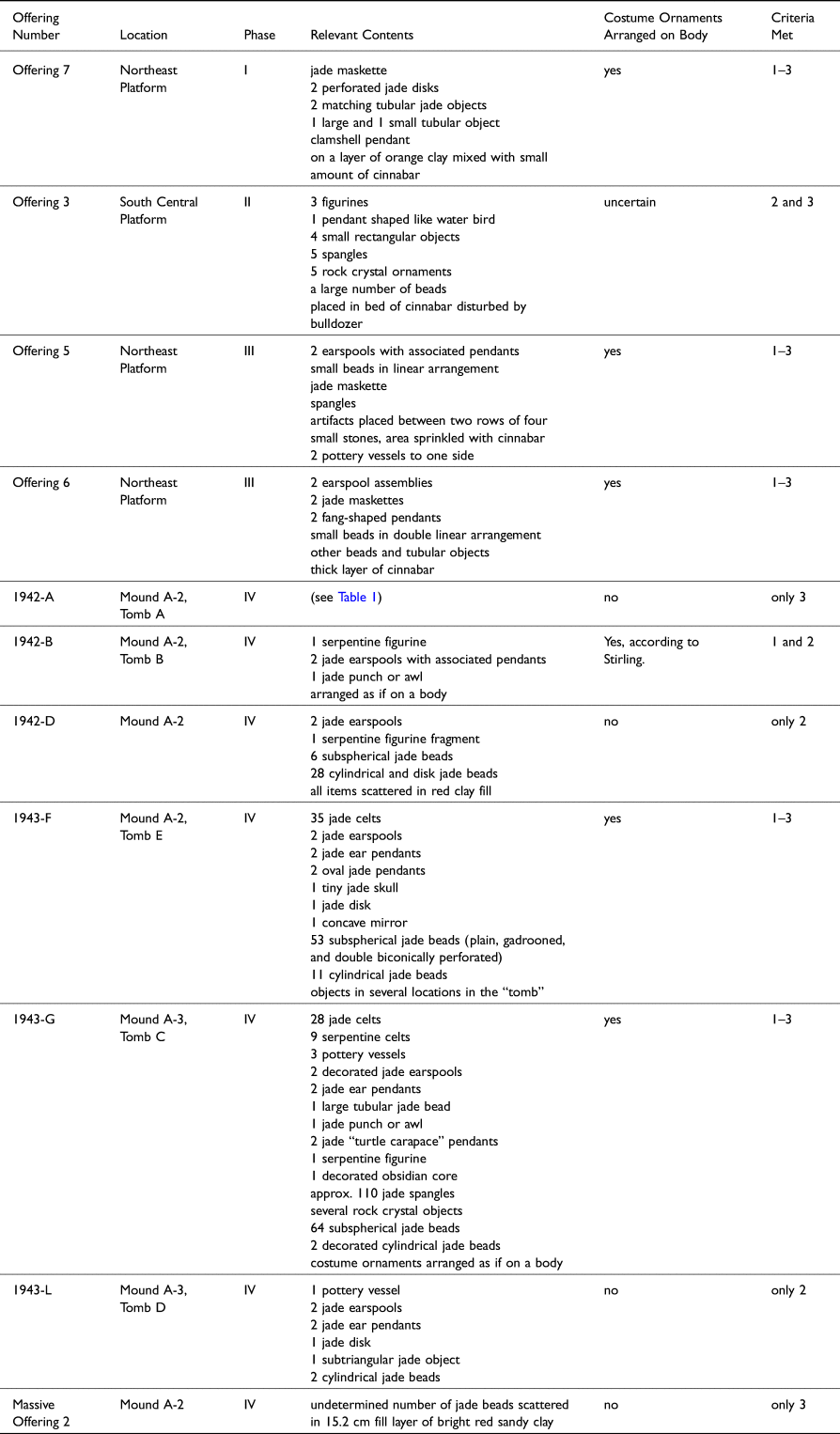
Tomb A is included in this category, even though it is unclear whether it meets the first criterion. In recounting his finds in the red cinnabar layer, Stirling (Stirling and Stirling Reference Stirling and Stirling1942) mentioned approximately seven different locations of artifacts, which include two jade ear ornaments, two clay earspools, and a number of beads. They were not, however, in the discrete spatial relationships that would indicate the decomposition of bodies wearing these objects. The beads in particular were described as “scattered” and not arranged as if strung. There is nothing in his description to indicate that the objects were directly associated with the assumed bundled human remains, which, as noted above, were considered by Drucker (Reference Drucker and Oehser1975:104) and Coe and Stuckenrath (Reference Coe and Stuckenrath1964:23) to be part of the offerings.
In sum, this type of deposit—the “surrogate burial”—has more members than any other category recognized among the La Venta small and large caches. It constitutes “a definite pattern, but one whose meaning in terms of La Venta culture is unknown to us” (Drucker and Heizer Reference Drucker and Heizer1965:58). With occurrences dating from Phase I to Phase IV, it is also a very “long-lived” pattern of ritual practices (Coe and Stuckenrath Reference Coe and Stuckenrath1964:24). Although the type was called a pseudoburial to “symbolize” (Drucker et al. Reference Drucker, Heizer and Squier1959:127) or “simulate” (Drucker Reference Drucker and Oehser1975:104) a burial, Drucker and Heizer (Reference Drucker and Heizer1965:58) noted that they could not ascertain whether these deposits were meant to represent specific individuals. Another possibility is suggested by the terms “surrogate” or “substitute,” proffered by Coe and Stuckenrath, rather than “pseudo,” meaning false—that the features do not symbolize anything but were considered substantive replacements for historical or fictive individuals who were presumably deceased, although this last descriptor is not inevitable.
Classifying the features in Table 2 as surrogate burials rather than burials is not a simple semantic difference. Insisting that the five “tombs” and some similar-appearing features were more than simulacra of human burials and must therefore be burials has misled archaeologists regarding Olmec society and the specific ritual and elite activities at La Venta. For over 50 years, it has impeded the development of other analytical and conceptual approaches to these features, their constituent artifacts, and their placements in space and time. It has also resulted in unwarranted speculation concerning the presumed mortuary purposes of Mounds A-2 and A-3, and even Complex A itself, ignoring the many other practices and structures in the complex that seem to have little directly to do with venerating the dead.
The placement of costume items as if on an absent body has always been the most compelling aspect of these features, although it does not apply to all proposed instances (Table 2). More attention could be given to those objects and not the missing corpses, such as the associative patterns they reveal as personal assemblages, including status claims and ideals of elite costume (e.g., Joyce Reference Joyce2000a:44–47). It is highly likely that many of these objects had their own significance as the inalienable property of elite corporate groups (Clark and Colman Reference Clark and Colman2014). As such they would index those groups, modeled as social “houses” (Gillespie Reference Gillespie, Mills and Walker2008), even if not necessarily referencing their individual members, within a highly sanctified public arena.
Still to be considered is why or to what effect these “non-present” bodies were evoked by the ritual stewards of Complex A. Arguably, it was archaeologists who rendered “visible,” at least in interpretation, bodies that were always “invisible,” non-existent. Nevertheless, these “object-like absences” or “quasi-presences” (Fowles Reference Fowles, Bille, Hastrup and Sørensen2010:27) were materially created precisely by arranging enduring ornaments as if bodies were present. The body was “experienced as a presence precisely because its absence is marked or emphatic” (Fowles Reference Fowles, Bille, Hastrup and Sørensen2010:25). As Fowles (Reference Fowles, Bille, Hastrup and Sørensen2010:25) further observed, such absences “stand before us as entity-like presences with which we must contend.” He was speaking not only of how archaeologists must contend with object-like absences, but also how the peoples who created or confronted them engaged emotionally or psychologically with “that which is manifestly not present” (Fowles Reference Fowles, Bille, Hastrup and Sørensen2010:27). In other words, rather than merely “non-present,” these bodies were “non-absent,” and as such would never perish or decay, remaining ambivalent, even uncanny (Domanska Reference Domanska2006:345) compared to the usual fate of human remains. Attention should rightly turn toward the ritual stewards or caretakers of Complex A, whose invisible hands created the non-present bodies. What were their sources of legitimacy and authority? They may have been leaders of several chiefly houses collaborating in the care of Complex A, at least through its first three phases (Gillespie Reference Gillespie, Mills and Walker2008).
Conclusions
In conclusion, the totality of the empirical archaeological—that is, taphonomic and stratigraphic—evidence supports the presumption that the Complex A features designated as tombs or burials were not created as the final resting places of recently deceased human individuals, i.e., as primary burials. Furthermore, the so-called tombs of Mound A-2, in particular, were put in place over a very short period of time within construction Phase IV. Mound A-2 was not erected as a mausoleum to house the remains of a series of religious or secular leaders following their deaths. The same is likely true for Mound A-3 and its Tombs C and D, which also date to the same construction phase. These evidentiary based findings thus warrant a reassessment of political-ritual actions and their consequences at late La Venta.
Throughout much of its use life, Complex A facilitated and mediated many ritual practices that were signally important to La Venta as a major regional center. Since the first excavation projects in the 1940s, the archaeological focus on a few late kings—evidenced by certain “tombs “as well as depictions in sculptures—has ultimately detracted from more detailed investigations of social and political organization (e.g., Gillespie Reference Gillespie, Mills and Walker2008) and how it compares to earlier San Lorenzo and contemporaneous Middle Formative regional centers in Mesoamerica. For example, high-effort graves of elite single individuals wearing jade regalia were placed in non-domestic architecture elsewhere in Mesoamerica in the Middle Formative (Joyce Reference Joyce, Grove and Joyce1999). This begs the question of how and why La Venta was participating in these more widespread elite practices, which include monumental architecture and stone sculpture as well as the restrictive use of green jade (Joyce Reference Joyce, Grove and Joyce1999:41–42, Reference Joyce, Richards and Van Buren2000b:67), but without real burials.
The focus on the “tombs” of the last phase of its construction has also drawn attention away from other ritual practices within Complex A and how they changed or remained stable throughout its Formative occupation. Significantly, Massive Offering 2, which was believed by the 1955 excavators to initiate Phase IV (Drucker et al. Reference Drucker, Heizer and Squier1959:125), has certain attributes that link it to the earlier pattern of surrogate burials. At the bottom of the deep pit dug into Mound A-2 is a unique layer of bright red, sandy clay, within which at least a few jade beads were scattered before placing the single layer of serpentine blocks (Figure 11-3). Although not cinnabar, the color matches criterion 3 for surrogate burials (see Table 2). Offerings 9 and 11 within the fill of Massive Offering 2 also include jade beads in association with red cinnabar. These data suggest that, from their initiation, the Phase IV activities at Mound A-2 were materially associated with “mortuary” practices, regardless of whether actual bodies were deposited. The single serpentine rectangular block encountered in Tomb A (Table 1; Drucker Reference Drucker1952:25) may have indexed the layer of serpentine blocks that covered the bottom of the Massive Offering 2 pit, and it is comparable in size to many of those blocks.
Phase IV activities at Mound A-2 constituted a development of previous practices in Complex A's Ceremonial Court, but also an abrupt transformation (Gillespie Reference Gillespie, Mills and Walker2008). The much more elaborate surrogate burials (Tombs A–C) were arranged on a north-south center line alignment not previously emphasized and were positioned outside the Ceremonial Court itself. The earlier, simpler features of this type were within the Court's perimeter and primarily in the Northeast Platform, off the centerline. Observing these patterns and how they changed over time should provide more insights than static classifications of features into universal types.
Indeed, capping the entire Complex for the first time in a uniform matrix, one of a reddish color, may have manifested a new funereal symbolism for this entire mound group north of the pyramid that was not evident in previous stages of use. The Complex's metaphorical “death” was accompanied by an abandonment of ritual maintenance that had gone on for generations, even as it remained a sanctified space subject to additional deposits of offerings (post-Phase IV; Drucker et al. Reference Drucker, Heizer and Squier1959:215–229). This need not have signaled the immediate cessation of La Venta's regional political influence, as is often thought. Nevertheless, it certainly constituted a major historical event in late Middle Formative La Venta, a probable shift in governance linked to importing many tons of new kinds of stone to greatly embellish Complex A, including for the surrogate burials deposited in Mounds A-2 and A-3. It occurred at a time when “Mesoamerica” itself was beginning to take shape, at a place on the frontier between western Mesoamerica and the Maya area. A wider lens is needed to grasp the totality and interrelatedness of all these actions in the broader context of Gulf Coast and Mesoamerican-wide sociopolitics.
Supplementary material
The supplementary material for this article can be found at https://doi.org/10.1017/S0956536122000232
Acknowledgments
We gratefully acknowledge the following individuals: Vyrtis Thomas, Archives Specialist, and Catherine O'Sullivan, Reference Archivist, of the National Anthropological Archives, who provided assistance to Gillespie in consulting the Robert Fleming Heizer Papers in 2007. George Stuart had graciously sent Gillespie a copy of his records on the Richard Stewart photographs taken during the 1942–1943 Smithsonian-National Geographic excavations, and Bill Bonner facilitated Gillespie's 2007 consultation of the National Geographic Society Image Collection. That initial research was funded in part by the Foundation for the Advancement of Mesoamerican Studies, Inc. (FAMSI), Grant #07054, awarded to Gillespie in 2007; FAMSI funds were not involved in the analysis or writing of this article. John Clark thoughtfully provided Arlene Colman's Master's thesis on La Venta to Gillespie. The final paper is improved by the comments of three anonymous reviewers, although any omissions or errors are the authors’ responsibility. Rocío M. López Cabral provided the Spanish abstract.


 Open access