
1. Introduction
In his Foreword to the XXXIV Cold Spring Harbor Symposium on Quantitative Biology (‘The Mechanism of Protein Synthesis’), Cairns wrote: ‘A science comes of age when the principles on which it was founded have been vindicated and are replaced, as an occupation, by the accumulation of detail’ (Cairns, Reference Cairns1969). Cairns's view of the mechanism of protein synthesis in 1969, a view shared by many leading molecular biologists of the day, can be likened to that of a group of cavemen trying to figure out how a Ferrari works (Noller, Reference Noller2017). After careful experiments, they draw the following conclusions: The gas pedal makes the car go faster, the brake pedal makes it slow down, the steering wheel makes it turn right or left, and so on. But any automobile mechanic would consider this macroscopic phenomenology, not mechanism or principles. Conversely, discovering that explosions of gasoline aerosols drive the movement of pistons to create torque on the crankshaft, which then drives the wheels, and so on, is not just ‘accumulation of detail’, but the fundamental mechanism that made the automobile possible. Even after 48 more years of ribosomology, we do not yet understand protein synthesis – especially the mechanism of translocation – with the same clarity with which we understand how cars work. But we have learned a great deal about what is under the hood, and are asking many of the right questions. And this, together with the emergence of an impressive arsenal of powerful tools, has fueled optimism that a true understanding of fundamental mechanism may become a reality in the near future.
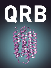
Ribosomes are remarkable ribonucleoprotein complexes. Even the smallest (bacterial and archaeal) ribosomes are very large and complex, with molecular weights of ~2·5 MDa, containing ~4500 nucleotides of ribosomal RNA and more than 50 different proteins (Fig. 1). Their structural complexity is mirrored in the complexity of the diverse mechanisms responsible for initiation, elongation and termination of protein synthesis. In recent years, there has been a growing appreciation for the importance of the structural dynamics of the ribosome for its function. This is particularly clear for translocation, without question the most complex and challenging of ribosomal mechanisms. Ribosomal translocation has been the subject of intensive investigation and several recent reviews (Achenbach & Nierhaus, Reference Achenbach and Nierhaus2015; Belardinelli et al. Reference Belardinelli, Sharma, Peske, Wintermeyer and Rodnina2016b; Frank, Reference Frank2012; Frank & Gonzalez, Reference Frank and Gonzalez2010; Holtkamp et al. Reference Holtkamp, Wintermeyer and Rodnina2014; Ling & Ermolenko, Reference Ling and Ermolenko2016; Munro et al. Reference Munro, Sanbonmatsu, Spahn and Blanchard2009; Rodnina & Wintermeyer, Reference Rodnina and Wintermeyer2011). In this paper, our main focus is on results from structural studies of the bacterial ribosome that have begun to reveal in great detail its machine-like properties. A major revelation is the extent to which ribosome structural dynamics is based on ribosomal RNA.
Cross-section view of the ribosome. A peptidyl-tRNA (orange) is shown bound to the P site in the intersubunit cavity of the Thermus thermophilus 70S ribosome (Yusupov et al. Reference Yusupov, Yusupova, Baucom, Lieberman, Earnest, Cate and Noller2001). The 30S subunit is on the left, with 16S rRNA (cyan) and 30S proteins (blue) and the mRNA (yellow) winding around the neck between the head (top) and body (below) domains. The anticodon end of the peptidyl-tRNA contacts a codon in the 30S P site. The 50S subunit is shown at the right, with its 23S rRNA in grey, 5S rRNA in grey-blue (top right) and 50S proteins in magenta. A modeled α-helical nascent polypeptide chain is shown attached to the acceptor end of the tRNA in the peptidyl transferase active site, passing through the polypeptide exit channel at the lower right.

2. Overview of protein synthesis
Protein synthesis is carried out by the ribosome, a large nucleoprotein complex that is found in all organisms (Rodnina et al. Reference Rodnina, Wintermeyer and Green2011). If the ribosome had been discovered by enzymologists, instead of by electron microscopists, it would probably be named ‘polypeptide polymerase’. Protein synthesis is also called translation, because it mediates information transfer between the two very different molecular languages of RNA (or DNA) and proteins. In keeping with its bilingual role in biology, the ribosome itself is composed of both RNA and protein – about 60% RNA in bacteria and archaea, and about 50% RNA in eukarya. Contrary to everyone's expectations in 1969, the central functions of the ribosome have turned out to be based on its RNA, not its proteins. Ribosomal proteins are essential for correct assembly of ribosomes, and appear to facilitate, but do not define, its functions. This surprise was no mere detail, but a complete reversal of the prevailing paradigm.
Like other polymerase reactions, the main phases of translation can be divided into initiation, elongation and termination. An additional phase, called recycling (Janosi et al. Reference Janosi, Hara, Zhang and Kaji1996), clears the ribosome of its remaining mRNA and tRNA following completion of translation of each mRNA. Although there are variations between the mechanisms of initiation, termination and recycling between the three domains of life, the mechanisms of elongation are virtually identical for all ribosomes, according to our current knowledge. As we shall see, there are three binding sites for tRNA on all ribosomes – the A (aminoacyl), P (peptidyl) and E (exit) sites (Fig. 2). Here, we shall focus on the bacterial 70S ribosome, for which we have the most extensive structural and functional information. In the presence of initiation factors IF1, IF2 and IF3, the initiator fMet-tRNA is fixed at the correct AUG (or occasionally GUG or UUG) start codon in the small (30S) subunit P site, establishing the translational reading frame. The large (50S) subunit then joins the 30S subunit, along with departure of the initiation factors, creating a 70S ribosome containing the initiator tRNA with its f-Met group positioned in the P site of the peptidyl transferase catalytic center of the 50S subunit, and the second codon of the mRNA exposed in the 30S A site.
Locations of the tRNA binding sites. Top view of the T. thermophilus 70S ribosome, relative to Fig. 1, showing tRNAs bound the A (yellow), P (orange) and E (red) sites (Yusupov et al. Reference Yusupov, Yusupova, Baucom, Lieberman, Earnest, Cate and Noller2001). The 30S subunit is at the bottom (cyan and blue) and the 50S subunit (grey, magenta) is at the top.

The elongation phase then begins with delivery of a cognate aminoacyl-tRNA to the ribosome, most likely by trial and error, by a ternary complex made up of aminoacyl-tRNA, the GTPase elongation factor EF-Tu and GTP. The aminoacyl-tRNA binds initially in the A/T state, in which its anticodon binds to the A-site codon, while its aminoacyl end is sequestered by EF-Tu. When a cognate tRNA is bound, GTP is hydrolyzed, resulting in a conformational change in EF-Tu that releases it from its tRNA and from the ribosome. The aminoacyl end of the tRNA is then accommodated into the A site of the 50S peptidyl transferase center, where a peptide bond is formed by attack of its amino group on the f-Met acyl group, catalyzed by 23S ribosomal RNA. This results in formation of f-Met-aminoacyl-tRNA, a peptidyl-tRNA, which now occupies the ribosomal A site, while the deacylated initiator tRNA remains bound to the P site.
In order to continue polypeptide synthesis, the next mRNA codon needs to be brought into the 30S A site (the decoding site), and the peptidyl-tRNA needs to move to the P site, which must therefore be vacated by the deacylated tRNA, which in turn moves to the E site (Fig. 3). Importantly, the tRNAs must be moved in precise synchrony with movement of the mRNA, to avoid losing the translational reading frame, an otherwise catastrophic event. All of these steps take place within ~50–100 ms during each round of translocation, which is catalyzed by another GTPase, elongation factor EF-G.
Movement of tRNA through the ribosome. (Left) A view of tRNAs bound to the A, P and E sites of the 70S ribosome, as in Fig. 2. The dashed red arrow shows the direction of translocation of tRNA during the elongation phase of protein synthesis. (Right) A schematic diagram of tRNAs bound to the ribosome in their classical (A/A, P/P and E/E) states.

The steps of aminoacyl-tRNA selection, peptide bond formation and translocation are repeated as necessary until a stop codon (UAG, UAA or UGA) enters the 30S A site. Stop codons are not recognized by tRNA, but by the class I release factors RF1 (UAG or UAA) or RF2 (UAG or UGA). A conformational change in the release factor moves its domain 3 into the peptidyl transferase center where it catalyzes hydrolysis of the peptidyl-tRNA ester bond, releasing the completed polypeptide chain. The class 2 release factor RF3 is believed to be involved in release of RF1 and RF2 from the termination complex, followed by clearing of the remaining mRNA and deacylated tRNA from the ribosome by ribosome recycling factor (RRF) in combination with EF-G.
3. Translocation
Coupled movement of mRNA and tRNA is catalyzed by EF-G·GTP. The minimal requirements for EF-G-catalyzed translocation are a full-length tRNA bound to the P site and a tRNA anticodon stem-loop in the A site (Joseph & Noller, Reference Joseph and Noller1998).
The role of GTP hydrolysis in translocation is not fully understood. Early studies by Kaziro and co-workers (Inoue-Yokosawa et al. Reference Inoue-Yokosawa, Ishikawa and Kaziro1974) showed that EF-G can catalyze translocation using the non-hydrolyzable GTP analog GDPCP; they proposed that GTP hydrolysis is mainly required for release of EF-G from the ribosome. More recently, Rodnina et al. (Reference Rodnina, Savelsbergh, Katunin and Wintermeyer1997) showed that GTP hydrolysis precedes translocation, and accelerates translocation by at least 50-fold over that observed using the non-hydrolyzable analog GDPNP; they proposed that EF-G serves as a motor protein by coupling the free energy of GTP hydrolysis to translocation.
Although the rate of translocation is clearly accelerated by EF-G·GTP, the observation that translocation can nevertheless occur in the absence of EF-G or GTP, albeit very slowly, implies that its fundamental mechanism is embodied in the ribosome rather than in EF-G (Ermolenko et al. Reference Ermolenko, Cornish, Ha and Noller2013; Fredrick & Noller, Reference Fredrick and Noller2003; Gavrilova & Spirin, Reference Gavrilova and Spirin1971; Pestka, Reference Pestka1968, Reference Pestka1969). EF-G-catalyzed translocation of tRNAs in the absence of mRNA (Tnalina et al. Reference Tnalina, Belitsina and Spirin1982) shows that the mechanism acts directly on tRNA; it is not clear whether it also acts directly on mRNA, or whether mRNA is moved through the ribosome passively, by virtue of its codon–anticodon interactions with tRNA.
4. Translocation involves large-scale movements of tRNA
Based on the existence of distinct A, P and E binding sites for tRNA on the ribosome (Rheinberger et al. Reference Rheinberger, Sternbach and Nierhaus1981; Watson, Reference Watson1964), it seemed inescapable that translocation must involve large-scale molecular movements. This view was challenged by Woese (Reference Woese1970), who proposed an ingenious ‘reciprocating ratchet’ model, in which alternate flipping of the tRNA anticodon loops from 3′-stacking to 5′-stacking reversed the orientation of mRNA such that the identities of the A and P sites were swapped after formation of each peptide bond. However, unambiguous identification of separate A, P and E sites by chemical probing (Moazed & Noller, Reference Moazed and Noller1986, Reference Moazed and Noller1989a, Reference Moazed and Noller1990) and x-ray crystallography (Cate et al. Reference Cate, Yusupov, Yusupova, Earnest and Noller1999) eventually ruled out this mechanism, leaving large-scale movement as the sole possibility. The dimensions of the ribosome and the locations of its tRNA binding sites predicted that the tRNAs must move through distances of ~20 to ~50 Å during the different steps of translocation (Noller et al. Reference Noller, Yusupov, Yusupova, Baucom and Cate2002). Given these constraints, one could imagine mechanisms of two extreme types: movement of tRNAs from one site to another by simple diffusion, or large-scale conformational rearrangements within the ribosome structure that guide or escort the tRNAs between their different binding sites. As we shall see, the latter turns out to be the case.
The earliest evidence for intermediate states during translocation was the discovery of hybrid states from chemical probing experiments (Moazed & Noller, Reference Moazed and Noller1989b). Identification of characteristic chemical footprints on 16S and 23S rRNA for tRNA bound in the A, P and E sites led to experiments in which pre-translocation ribosome complexes were stalled in different states by excluding EF-G and GTP. The results were unexpected. In the simplest experiment, the peptidyl-tRNA analogue N-Ac-Phe-tRNA was bound to the P site in the presence of a poly(U) mRNA, and treated with puromycin, which reacts with the peptidyl-tRNA to form an N-Ac-Phe-puromycin product, leaving a deacylated tRNA bound to the ribosome. Instead of a P-site tRNA footprint, the pattern showed protection of the expected 16S rRNA bases characteristic for the 30S subunit P site, but an E-site footprint for the 23S rRNA in the 50S subunit. This result was interpreted to mean that the anticodon end of the tRNA had remained in the 30S P site while its acceptor end had moved from the P site to the E site of the 50S subunit. Next, N-Ac-Phe-tRNA was again bound to the P site, but instead of adding puromycin, a Phe-tRNA was bound to the A site. In this experiment, P and A footprints were observed for the 30S subunit, while P and E footprints were found for the 50S subunit. It was concluded that, in the absence of EF-G and GTP, the acceptor ends of the tRNAs were moving spontaneously from the A and P sites to the P and E sites of the 50S subunit, while their anticodon ends remained in the A and P sites of the 30S subunit, creating what were termed A/P and P/E hybrid states (Fig. 4). Addition of EF-G and GTP to this stalled complex resulted in footprints that were indistinguishable from normal P-site and E-site footprints, suggesting that the A/P and P/E states were authentic intermediates in the translocation process. In other words, the tRNAs move through the ribosome in two steps, first on the large subunit and then on the small subunit. It further indicated that while the first step could happen spontaneously, the second step required EF-G and GTP, and was likely rate-limiting.
Movement of tRNA into hybrid states. Schematic diagram showing the hybrid states mechanism for movement of tRNA through the ribosome (Moazed & Noller, Reference Moazed and Noller1989b). The tRNAs move from the classical A/A and P/P states into the hybrid A/P and P/E states, and finally into the classical E/E and P/P states.

Green and coworkers asked whether the observed hybrid states of tRNA binding are authentic physiological intermediates in the translocation reaction (Dorner et al. Reference Dorner, Brunelle, Sharma and Green2006). In their experiments, they took advantage of the Watson–Crick base pairing between bases in the CCA acceptor ends of the tRNAs with the A and P loops of 23S rRNA (Kim & Green, Reference Kim and Green1999; Nissen et al. Reference Nissen, Hansen, Ban, Moore and Steitz2000; Samaha et al. Reference Samaha, Green and Noller1995). By using mutant ribosomes and/or tRNAs to disrupt base pairing between tRNA and the A or P loops, they were able to selectively create complexes in which the tRNAs were bound exclusively in classical A/A and P/P states or in the A/P and P/E hybrid states. They showed not only that tRNAs bound in hybrid states were translocated by EF-G·GTP, but that they were translocated more efficiently than tRNAs bound in classical states. These findings showed that hybrid-state ribosomes are the preferred substrate for EF-G-catalyzed translocation and thus are likely a biologically relevant translocation intermediate.
5. Intersubunit rotation
The first clear indication of a role for ribosome structural dynamics in translocation came from cryo-EM studies by Frank & Agrawal (Reference Frank and Agrawal2000). They observed that in ribosomes containing EF-G trapped on the ribosome with fusidic acid, the 30S subunit is rotated counterclockwise by about 6° relative to its orientation in the absence of EF-G, which they termed a ‘ratchet-like motion’. Based on this, they proposed a two-step mechanism of translocation involving first intersubunit rotation and opening of the mRNA channel, followed by advancement of the mRNA-tRNA complex in the direction of rotation of the 30S subunit following GTP hydrolysis.
Direct evidence for the role of intersubunit rotation in translocation was obtained in experiments in which a reversible disulfide crosslink was formed between proteins S6 in the 30S subunit and L2 in the 50S subunit (Horan & Noller, Reference Horan and Noller2007). This crosslink blocked protein synthesis, but as soon as it was broken, protein synthesis immediately resumed. The block was found to be in the step of translocation. This experiment showed that intersubunit movement of some kind is essential for translocation
Although intersubunit rotation is essential for translocation, it does not result in productive translocation, but instead results in an intermediate state that is likely the hybrid state that was inferred from chemical probing experiments (Moazed & Noller, Reference Moazed and Noller1989b; Spiegel et al. Reference Spiegel, Ermolenko and Noller2007). Unlike translocation, intersubunit rotation is spontaneous and reversible. This was shown directly in FRET experiments using doubly-labeled 70S ribosomes constructed by in vitro reconstitution of 30S subunits containing a donor fluorophore attached to either protein S6 or S11 on the 30S body, and 50S subunits containing an acceptor on the globular N-terminal domain of protein L9. Bulk FRET experiments showed spontaneous intersubunit rotation upon peptide bond formation (Ermolenko et al. Reference Ermolenko, Majumdar, Hickerson, Spiegel, Clegg and Noller2007a) or binding of the antibiotic viomycin (Ermolenko et al. Reference Ermolenko, Spiegel, Majumdar, Hickerson, Clegg and Noller2007b). Single-molecule FRET experiments using similar FRET pairs revealed rapid, reversible, spontaneous fluctuations between the classical and rotated states in the absence of EF-G or GTP (Cornish et al. Reference Cornish, Ermolenko, Noller and Ha2008; Qin et al. Reference Qin, Yu, Zuo and Cornish2014; Sharma et al. Reference Sharma, Adio, Senyushkina, Belardinelli, Peske and Rodnina2016).
Consistent with spontaneous fluctuations in intersubunit rotation, single-molecule FRET experiments also showed spontaneous, reversible movement of tRNA between classical and hybrid binding states (Adio et al. Reference Adio, Senyushkina, Peske, Fischer, Wintermeyer and Rodnina2015; Altuntop et al. Reference Altuntop, Ly and Wang2010; Blanchard et al. Reference Blanchard, Kim, Gonzalez, Puglisi and Chu2004; Chen et al. Reference Chen, Stevens, Kaur, Cabral, Liu, Wang, Zhang, Rosenblum, Smilansky, Goldman and Cooperman2011; Kim et al. Reference Kim, Puglisi and Chu2007; Munro et al. Reference Munro, Altman, O'Connor and Blanchard2007, Reference Munro, Altman, Tung, Cate, Sanbonmatsu and Blanchard2010a). In addition, the 50S subunit L1 stalk, whose movement is correlated with formation of the P/E hybrid state (Cornish et al. Reference Cornish, Ermolenko, Staple, Hoang, Hickerson, Noller and Ha2009), also undergoes spontaneous, reversible fluctuations in the absence of EF-G (Cornish et al. Reference Cornish, Ermolenko, Staple, Hoang, Hickerson, Noller and Ha2009; Fei et al. Reference Fei, Kosuri, Macdougall and Gonzalez2008, Reference Fei, Bronson, Hofman, Srinivas, Wiggins and Gonzalez2009; Munro et al. Reference Munro, Altman, Tung, Cate, Sanbonmatsu and Blanchard2010a). Taken together, these results strongly support the conclusion that rotational movement of the >800 kD 30S subunit can be driven by thermal energy alone.
Another single-molecule FRET study (Marshall et al. Reference Marshall, Dorywalska and Puglisi2008), using fluorescently tagged DNA oligonucleotide probes attached by hybridization to rRNA helices h44 and H101 in the small and large subunit, respectively, also observed spontaneous intersubunit rotation, but concluded that rotation is irreversible in the absence of EF-G·GTP. To rationalize this discrepancy, the authors suggested that the S6-L9 and S11-L9 pairs were reporting on movement of the 50S subunit L1 stalk (Marshall et al. Reference Marshall, Dorywalska and Puglisi2008), or the 30S subunit head (Chen et al. Reference Chen, Tsai, O'LEARY, Petrov and Puglisi2012), rather than intersubunit rotation. This seems highly unlikely, since S6 and S11 are located on the 30S body rather than the head, and the N-terminal domain of L9 is bound to the core of the 50S subunit body. Furthermore, the S6 and S11 probe positions were predicted to give anti-correlated changes in FRET upon intersubunit rotation, exactly as observed (Ermolenko & Noller, Reference Ermolenko and Noller2011).
Ensemble stopped-flow FRET experiments using doubly-labeled ribosomes provided direct real-time observation of intersubunit rotation during translocation (Ermolenko & Noller, Reference Ermolenko and Noller2011). When pre-translocation ribosome complexes were mixed with EF-G·GTP, a rapid change in FRET efficiency consistent with counter-clockwise intersubunit rotation was followed by a slower change corresponding to reverse (clockwise) rotation. Translocation of mRNA occurred during reverse rotation, establishing that intersubunit rotation is indeed occurring during mRNA movement. Puglisi and co-workers used zero-mode waveguides to monitor intersubunit FRET changes between fluorescent oligonucleotides hybridized to engineered sites in16S and 23S rRNA in single ribosomes (Chen et al. Reference Chen, Petrov, Tsai, O'LEARY and Puglisi2013). These studies showed the occurrence of intersubunit rotation during multiple rounds of translocation in translating ribosomes.
Why is formation of hybrid-state binding of tRNA coupled to intersubunit rotation? Rigid-body modeling predicted that some of the contacts between the elbow and acceptor ends of hybrid-states tRNAs and their respective binding sites could not be satisfied in the context of the classical-state ribosome (Noller et al. Reference Noller, Yusupov, Yusupova, Baucom and Cate2002). The first direct structural evidence came from cryo-EM studies of complexes of ribosomes formed with deacylated tRNA in the P site and peptidyl-tRNA in the A site, in the absence of EF-G. Reconstructions of sub-populations of these particles in which the 30S subunit was trapped in the rotated state, at 8·9 Å (Agirrezabala et al. Reference Agirrezabala, Lei, Brunelle, Ortiz-Meoz, Green and Frank2008) and 16 Å (Julian et al. Reference Julian, Konevega, Scheres, Lazaro, Gil, Wintermeyer, Rodnina and Valle2008) resolution were able to resolve tRNAs bound in positions that were consistent with binding in A/P and P/E hybrid states. Definitive evidence came from a 3·2 Å resolution x-ray crystal structure of ribosomes bound with a deacylated tRNA and ribosome recycling factor, which showed both large-scale intersubunit rotation and binding of tRNA in the P/E hybrid state (Dunkle et al. Reference Dunkle, Wang, Feldman, Pulk, Chen, Kapral, Noeske, Richardson, Blanchard and Cate2011). These studies also showed that rotation of the 30S subunit is accompanied by rearrangement of several intersubunit bridges and of the L1 stalk of the 50S subunit (Agirrezabala et al. Reference Agirrezabala, Lei, Brunelle, Ortiz-Meoz, Green and Frank2008; Dunkle et al. Reference Dunkle, Wang, Feldman, Pulk, Chen, Kapral, Noeske, Richardson, Blanchard and Cate2011).
6. Rotation of the 30S subunit head domain
Although rapid intersubunit rotation can occur in the absence of EF-G, translocation cannot. What, then, is the EF-G-dependent event that unlocks the ribosome to allow movement of mRNA and tRNA? As early as 1988, Brimacombe and coworkers proposed that tRNAs might be moved through the ribosome by a rocking motion of the 30S subunit head domain in what they termed a ‘turnstile model’ for translocation (Stiege et al. Reference Stiege, Stade, Schuler and Brimacombe1988). Experimental evidence implicating movement of the 30S subunit head domain during tRNA translocation came from the first all-atom crystal structure of the 70S ribosome (Schuwirth et al. Reference Schuwirth, Borovinskaya, Hau, Zhang, Vila-Sanjurjo, Holton and Cate2005), and from a cryo-EM structure of the yeast 80S ribosome bound elongation factor eEF2 trapped with the translocation inhibitor sardorin (Spahn et al. Reference Spahn, Gomez-Lorenzo, Grassucci, Jorgensen, Andersen, Beckmann, Penczek, Ballesta and Frank2004). The 70S structure revealed a 13 Å constriction between the 30S P and E sites. Since a ~22 Å anticodon stem-loop (ASL) must pass from the P site to the E site during translocation, this constriction would present a severe steric barrier to tRNA movement (Fig. 5). Schuwirth et al. proposed that the steric clash could be resolved by rotation of the small subunit head domain as seen in the 80S-sardorin structure.
Constriction of the path between the 30S P and E sites. A close-up view of the 30S subunit showing a 13 Å constriction between the P and E sites in the classical-state ribosome, presenting a steric block to movement of the anticodon stem of the P-site tRNA during translocation (Schuwirth et al. Reference Schuwirth, Borovinskaya, Hau, Zhang, Vila-Sanjurjo, Holton and Cate2005).

But, does rotation of the 30S head domain actually occur during translocation? The first direct evidence came from a 7·8 Å cryo-EM structure of T. thermophilus 70S ribosomes containing a co-purified, endogenous tRNA to which EF-G was stably bound in the presence of GTP and fusidic acid (Ratje et al. Reference Ratje, Loerke, Mikolajka, Brunner, Hildebrand, Starosta, Donhofer, Connell, Fucini, Mielke, Whitford, Onuchic, Yu, Sanbonmatsu, Hartmann, Penczek, Wilson and Spahn2010). Classification of the resulting cryo-EM images identified a sub-population of particles trapped in what was termed the TIPOST state, containing ribosomes with 4° intersubunit rotation and 18° rotation of the 30S head domain. The ASL of the tRNA was bound to the P site of the 30S head but juxtaposed with E site elements of the 30S body, with its deacylated acceptor end bound in the E site of the 50S subunit; accordingly, they termed this the pe/E state, to indicate that the tRNA ASL was shared between the P and E sites of the 30S subunit while its CCA end was bound in the 50S E site. They proposed that this state represents an intermediate between the hybrid P/E and classical E/E states during translocation. Domain IV of EF-G was observed to contact helix h34 of 16S rRNA, possibly stabilizing rotation of the head of the 30S subunit, and thus keeping the ‘gate’ open for movement of the tRNA from the 30S P to the E site. Based on this structure, it was proposed that the mechanism of translocation involves a combination of motions involving forward and reverse intersubunit and 30S head rotations (Ratje et al. Reference Ratje, Loerke, Mikolajka, Brunner, Hildebrand, Starosta, Donhofer, Connell, Fucini, Mielke, Whitford, Onuchic, Yu, Sanbonmatsu, Hartmann, Penczek, Wilson and Spahn2010).
In the TIPOST structure, EF-G does not contact the P-site tRNA, and in fact is quite far away from it. This raised the question, how is the tRNA moved? Does binding of EF-G simply open the gate to allow the tRNA to diffuse passively from the P site to the E site, or is there an active mechanism? These questions were addressed by the crystal structures of 3 ribosome complexes containing a defined mRNA, tRNA and EF-G, trapped in intermediate states in the presence of fusidic acid or GDPNP (Zhou et al. Reference Zhou, Lancaster, Donohue and Noller2013). Two of the complexes, (Fus and GDPNP-I) showed essentially identical intersubunit rotation values of 3° and 30S head rotations of 15°, while the third complex (GDPNP-II) had an intersubunit rotation of 5° and head rotation of 18° (Fig. 6).
Structures of trapped 70S ribosome·EF-G complexes. (a, b) Overall views of (a) the non-rotated, classical-state post-translocation 70S·EF-G complex (Gao et al. Reference Gao, Selmer, Dunham, Weixlbaumer, Kelley and Ramakrishnan2009) and (b) the chimeric hybrid-state Fus 70S·EF-G complex, with tRNA bound in the pe/E state (Zhou et al. Reference Zhou, Lancaster, Donohue and Noller2013). (c–e) Interface views of the 30S subunit showing rotation of its body and head domains in the (c) classical EF-G-post state (Gao et al. Reference Gao, Selmer, Dunham, Weixlbaumer, Kelley and Ramakrishnan2009); (d) Fus complex (Zhou et al. Reference Zhou, Lancaster, Donohue and Noller2013); and (e) GDPNP-II complex (Zhou et al. Reference Zhou, Lancaster, Donohue and Noller2013). 16S rRNA, cyan; 30S proteins, blue; 23S rRNA, grey; 50S proteins, magenta; mRNA, green; P/P tRNA, red; E/E tRNA, yellow; pe*/E tRNA, red; EF-G, orange.

In all three structures, it could be seen that the tRNA does not simply move passively from the 30S P site towards the E site. Instead, the same 30S P-site contacts as seen in the non-rotated classical state between the 30S head domain and the tRNA were precisely maintained during movement. These include contacts between 16S rRNA bases G1338, A1339 and G966 and the base pairs at positions 29–30 and 40–41 in the anticodon stem of the tRNA, as well as contact with the C-terminal tails of proteins S9 and S13 (Fig. 7). In contrast, interactions with the P-site features in the body domain, including contact between the 790 loop of 16S rRNA and the tRNA backbone, as well as the stacking interaction between C1400 and the wobble base of the tRNA anticodon, were disrupted, allowing the ASLs to move into juxtaposition with E-site elements of the 30S body domain. Thus, as concluded in the cryo-EM study (Ratje et al. Reference Ratje, Loerke, Mikolajka, Brunner, Hildebrand, Starosta, Donhofer, Connell, Fucini, Mielke, Whitford, Onuchic, Yu, Sanbonmatsu, Hartmann, Penczek, Wilson and Spahn2010), the ASLs of the tRNAs were trapped between the P site of the head and the E site of the body. These states were termed ‘chimeric hybrid states’ by analogy with the beast of ancient Greek mythology, which was made of head and body elements from different animals. In the large subunit, the acceptor ends of the tRNAs were bound in the 50S E site virtually identically to that of classical E-site tRNA. Although the Fus complex and the GDPNP-I complex both showed a 15° rotation of the head domain, while the GDPNP-II complex, had an 18° head rotation (Fig. 6), contacts between the tRNA ASLs and the 30S head were identical for all three complexes, showing that the 30S subunit head is precisely ‘escorting’ the tRNA from the P to the E site (Fig. 7).
Transition of the tRNA ASL from the P/P state to the chimeric hybrid pe/E state. Closeup views from the interface (top) and side (bottom) of the ASL bound in the P/P state (left) and pe/E state in the Fus complex (right). During rotation of the 30S subunit head domain, the P-site contacts between the head and the ASL (including G1338, A1339 and G966 of 16S rRNA and the C-terminal tails of proteins S9 and S13) are precisely maintained, while P-site contacts with the 30S body domain (including C1400 and A790) are disrupted and replaced by contacts with E-site elements.

How does GTP promote binding of EFG to the ribosome? The ordered conformation of switch loop I of EF-G in its GTP state was seen for the first time in crystal structures of EF-G-ribosome complexes trapped in various states with non-hydrolyzable analogs of GTP, revealing multiple interactions that stabilize the relative orientations of domains I, III and V of EF-G (Chen et al. Reference Chen, Petrov, Tsai, O'LEARY and Puglisi2013; Pulk & Cate, Reference Pulk and Cate2013; Tourigny et al. Reference Tourigny, Fernandez, Kelley and Ramakrishnan2013; Zhou et al. Reference Zhou, Lancaster, Donohue and Noller2013). In the GDP state, rearrangement of these domains would result in disruption of contacts between domain III and the 30S subunit, and between domain V and the L11 stalk, which is likely responsible for release of EF-G from the ribosome. It was further shown that fusidic acid mimics the stabilizing contacts made between domains I and III by the ordered switch loop (Zhou et al. Reference Zhou, Lancaster, Donohue and Noller2013), explaining how fusidic acid can stabilize a conformation virtually identical to that of the GDPNP complex, promoting stable binding of EF-G to the ribosome in the presence of GDP.
An important caveat to the above-mentioned structures of chimeric hybrid-state ‘translocation intermediates’ is that they contained only one tRNA, whereas the natural substrate for EF-G is a ribosome complex containing both A- and P-site tRNAs. The first demonstration that the head-rotation mechanism for translocation from the P to the E site is indeed the same in an authentic translocation complex came from a 6·8 Å cryo-EM reconstruction of a translocation intermediate containing mRNA, EF-G and two tRNAs trapped with fusidic acid (Ramrath et al. Reference Ramrath, Lancaster, Sprink, Mielke, Loerke, Noller and Spahn2013). This structure also revealed the position of an A-site tRNA trapped in transit to the P site, an intermediate termed the ap/P state (Ramrath et al. Reference Ramrath, Lancaster, Sprink, Mielke, Loerke, Noller and Spahn2013). The ap/P-tRNA was contacted by domain IV of EF-G and P-site elements within the 30S subunit body, whereas the upstream pe/E-tRNA maintained tight interactions with P-site elements of the rotated 30S head, just as seen in the single-tRNA complex. Remarkably, a tight compaction of the tRNA pair could be seen in this state. In addition, this structure suggested how coupling of the movement of mRNA and tRNAs is promoted by the ribosome and EF-G during TIPOST formation, as discussed further below.
Movement of the A-site tRNA into a new chimeric hybrid state, termed the ap/ap state, was revealed in the crystal structure of a similarly trapped translocation intermediate containing two tRNAs (Zhou et al. Reference Zhou, Lancaster, Donohue and Noller2014). This intermediate shows intersubunit rotation of 2·7° and rotation of the 30S head domain by 21° (Fig. 8). The tip of domain IV of EF-G reaches into the 30S A site, simultaneously contacting elements of the mRNA, ap/ap tRNA, 16S rRNA and 23S rRNA. The position of the chimeric pe/E tRNA is closely similar to that seen in the one-tRNA complex described above, following the rotational movement of the 30S head domain. But as was seen in the cryo-EM structure of a two-tRNA complex (Ramrath et al. Reference Ramrath, Lancaster, Sprink, Mielke, Loerke, Noller and Spahn2013), the A-site ASL moves further than simply following head rotation, resulting in close approach of the ap/ap tRNA to the ASL of the pe/E tRNA (Fig. 9). This extra movement of the A-site ASL is necessary to avoid clash with domain IV of EF-G, which occupies the 30S A site in the chimeric state (Fig. 9).
Rotational movements of the 30S subunit. Movement of the tRNAs from the (a, c) classical A/A and P/P states into the (b, d) chimeric hybrid ap/ap and pe/E states is accompanied by a 2·7° intersubunit rotation and a 21° rotation of the 30S head domain (Zhou et al. Reference Zhou, Lancaster, Donohue and Noller2014).

Movement of the A- and P-site ASLs into the chimeric state. Closeup views of the 30S subunit showing tRNA anticodon stem-loops (ASLs) in the (a) classical (Jenner et al. Reference Jenner, Demeshkina, Yusupova and Yusupov2010) and (b) ap/ap chimeric hybrid intermediate (Zhou et al. Reference Zhou, Lancaster, Donohue and Noller2014) states. The P-site ASL moves precisely with rotation of the 30S head domain, while the A-site ASL moves further than the head rotation, to avoid clash with domain IV of EF-G.

How can one observe ribosome dynamics in real time? One of the most powerful methods is the use of FRET and other fluorescence-based methods to follow the motions of the ribosome and its ligands in real time during translocation, both in bulk and single-molecule experiments. This was first used to follow movement of tRNA from changes in distances between fluorescent-labeled tRNAs during translocation (Blanchard et al. Reference Blanchard, Kim, Gonzalez, Puglisi and Chu2004). Another approach has been to measure movement within the ribosome itself using doubly-labeled ribosomes constructed by in vitro reconstitution with ribosomal proteins derivatized with fluorescent probes (Ermolenko et al. Reference Ermolenko, Majumdar, Hickerson, Spiegel, Clegg and Noller2007a). An alternative strategy uses oligonucleotides containing fluorescent probes hybridized to engineered insertions in ribosomal RNA helices (Marshall et al. Reference Marshall, Dorywalska and Puglisi2008). Rodnina and co-workers have incorporated variations on the FRET approach, such as fluorescence quenching, to allow observation in parallel of several dynamic events on the ribosome during translocation, including binding and release of EF-G, as well as movement of tRNA, mRNA and structural domains of the ribosome (Belardinelli et al. Reference Belardinelli, Sharma, Caliskan, Cunha, Peske, Wintermeyer and Rodnina2016a). Another innovation is the use of zero-mode waveguides by Puglisi and co-workers to establish the timing of the arrival and departure of tRNAs and protein synthesis factors and other events during translation of a mRNA in real time (Uemura et al. Reference Uemura, Aitken, Korlach, Flusberg, Turner and Puglisi2010).
Direct observation of 30S head rotation during translocation came from bulk FRET experiments using two different labeling constructs (Fig. 10a and b ). In one construct (S12–S19), it was predicted that counter-clockwise head rotation would result in decreased FRET efficiency, and conversely for the other construct (S11–S13). Upon rapid mixing of EF-G·GTP with a pre-translocation complex, this is exactly what was observed (Fig. 10d ). This initial rapid movement was followed by a slower, reverse (clockwise) rotation, concomitant with mRNA translocation (Fig. 10c ).
Following 30S head rotation by ensemble FRET. Top: Distances between S12–S19 and S11–S13 FRET pairs in the (a) non-rotated classical and (b) head-rotated states. (c) Translocation of mRNA as measured by quenching of a pyrene dye attached to the 3′ end of the mRNA and (d) bulk stopped-flow FRET measurements showing anti-correlated changes in FRET efficiency upon mixing of EF-G·GTP at time = 0 with a ribosome pre-translocation complex (Guo & Noller, Reference Guo and Noller2012).

7. Interactions with domain IV of EF-G
How is the ribosome ‘unlocked’? Although some steps of translocation can occur spontaneously, productive translocation requires EF-G·GTP, as noted above. It was proposed by Khade and Joseph that disruption of the minor-groove interactions between the 16S rRNA elements of the decoding site and the codon-anticodon duplex in the 30S A site represent a rate-limiting step in EF-G-catalyzed translocation (Khade & Joseph, Reference Khade and Joseph2011). They observed that substitution of riboses by deoxyriboses or 2′-fluoro substitutions in the A-site codon stimulate the rate of EF-G-catalyzed translocation (Khade & Joseph, Reference Khade and Joseph2011). These substitutions destabilize the A-minor interactions in the decoding site, decreasing the affinity of the 30S A site for the codon-anticodon complex.
Cryo-EM and crystal structures of EF-G-ribosome complexes have shown that the conserved loops I and II protruding from the tip of domain IV of EF-G insert into the minor groove of the codon-anticodon helix in chimeric-hybrid and post-translocation complexes (Gao et al. Reference Gao, Selmer, Dunham, Weixlbaumer, Kelley and Ramakrishnan2009; Ramrath et al. Reference Ramrath, Lancaster, Sprink, Mielke, Loerke, Noller and Spahn2013; Zhou et al. Reference Zhou, Lancaster, Donohue and Noller2014); this set of contacts seems to replace the minor–groove interactions made by the universally conserved A1492 and A1493 of 16S rRNA in the A site of the 30S subunit during aminoacyl-tRNA selection and A-site tRNA binding (Ogle et al. Reference Ogle, Brodersen, Clemons, Tarry, Carter and Ramakrishnan2001). (Fig. 11). Mutations in loops I and II have in fact been shown to disrupt translocation (Liu et al. Reference Liu, Song, Zhang, Li, Lyu, Dong, Achenbach, Gong, Zhao, Nierhaus and Qin2014a; Savelsbergh et al. Reference Savelsbergh, Matassova, Rodnina and Wintermeyer2000), providing functional evidence for the participation of the tip of domain IV in this way. A final point is that aminoglycoside antibiotics that induce the flipped-out conformations of A1492 and A1493, favoring their interactions with the codon-anticodon duplex, are known inhibitors of translocation (Cabanas et al. Reference Cabanas, Vazquez and Modolell1978; Ogle et al. Reference Ogle, Brodersen, Clemons, Tarry, Carter and Ramakrishnan2001). Thus, there is an emerging likelihood that catalysis of translocation by EF-G may be triggered by replacement of the A1492-A1493 decoding site interactions by the tip of the flexible domain IV of EF-G.
Contact between domain IV of EF-G and the codon-anticodon duplex during translocation. Transparent surface renderings highlight interactions between the codon-anticodon duplex and (a) A1492-A1493 of 16S rRNA in the A site (Jenner et al. Reference Jenner, Demeshkina, Yusupova and Yusupov2010); and the tip of domain IV in (b) the ap/ap chimeric hybrid state (Zhou et al. Reference Zhou, Lancaster, Donohue and Noller2014); and (c) the post-translocated P/P state (Gao et al. Reference Gao, Selmer, Dunham, Weixlbaumer, Kelley and Ramakrishnan2009). Contacts between loops I and II at the tip of domain IV (orange) with the codon-anticodon duplex mimic the contacts made by 16S rRNA (cyan) in the decoding site, preserving codon-anticodon pairing during movement of mRNA (green) and tRNA (yellow, red).

Another long-standing question is, how are mRNA and tRNA translocated without losing the translational reading frame? Although the otherwise weak codon–anticodon pairing is stabilized in the ribosome by interactions with the A and P sites, what happens during the precarious interval between release from the A site and arrival in the P site? Based on the x-ray structure of an EF-G post-translocation complex (Gao et al. Reference Gao, Selmer, Dunham, Weixlbaumer, Kelley and Ramakrishnan2009) and a cryo-EM structure of an EF-G chimeric hybrid states complex (Ramrath et al. Reference Ramrath, Lancaster, Sprink, Mielke, Loerke, Noller and Spahn2013), it was proposed that synchronous movement of the mRNA codon and tRNA anticodon may be mediated via contact with the mobile domain IV of EF-G. As described above, the tip of domain IV inserts into the minor groove of the codon-anticodon helix, replacing the minor–groove interactions made by A1492-A1493 in the decoding site (Gao et al. Reference Gao, Selmer, Dunham, Weixlbaumer, Kelley and Ramakrishnan2009; Ramrath et al. Reference Ramrath, Lancaster, Sprink, Mielke, Loerke, Noller and Spahn2013; Zhou et al. Reference Zhou, Lancaster, Donohue and Noller2014). The x-ray structure of the EF-G chimeric hybrid complex containing two tRNAs (Zhou et al. Reference Zhou, Lancaster, Donohue and Noller2014) reveals that the interactions between the tip of domain IV of EF-G and the minor groove surface of the ap/ap codon–anticodon duplex are virtually identical to those made between EF-G and the P-site codon-anticodon duplex in a post-translocation complex (Gao et al. Reference Gao, Selmer, Dunham, Weixlbaumer, Kelley and Ramakrishnan2009). Thus, these contacts are precisely maintained during movement of the tRNA from the ap/ap state to the P/P state and a 21° rotation of the 30S head domain (Fig. 11b and c ). These findings support the proposal that domain IV plays a crucial role in coupling translocation of mRNA and tRNA. Domain IV of EF-G would then potentially play three roles in translocation: (i) to lower the energy barrier to movement of tRNA and the mRNA codon out of the A site; (ii) to position the ASL of the chimeric hybrid-state tRNA; and (iii) to prevent disruption of the translational reading frame during the vulnerable interval when codon–anticodon interaction is not stabilized by binding to the ribosome.
An unusual compact conformation of EF-G·GDP has been observed in the crystal structure of a pre-translocation complex containing an EF-G construct engineered by fusion of the N-terminus of EF-G to the N-terminal domain of ribosomal protein L9 (Lin et al. Reference Lin, Gagnon, Bulkley and Steitz2015) (Fig. 12). In the crystal lattice, this fusion stabilizes EFG-binding to the ribosome through interaction of the fused L9 domain with an adjacent 50S subunit that lacks L9. When bound to a pre-translocation complex containing A- and P-site tRNAs, the resulting structure shows that domains III, IV and V of EF-G·GDP are dramatically rearranged (Fig. 12b ), allowing EF-G to bind to the ribosome without clashing with the A-site tRNA (Fig. 11a ). When bound to ribosomes lacking an A-site tRNA, in a post-translocation state, the fused EF-G exhibited its normal, elongated conformation, but only in the presence of GDP-fusidic acid, which mimics the EFG·GTP state (Fig. 12b and d ).
A compact conformation of EF-G in the pre-translocation state. (a, c) Compact conformation of EF-G, (c) alone and (a) bound to the 70S ribosome, engineered by fusion of the N-terminus of EF-G to the N-terminal domain of ribosomal protein L9 (Lin et al. Reference Lin, Gagnon, Bulkley and Steitz2015). (b, d) EF-G in its elongated conformation.

While this flexibility of EF-G is intriguing, it is unclear when this compact state comes into play. According to single-molecule and ensemble FRET studies on EF-G in its free and ribosome-bound states, free-EF-G exists predominantly in a compact form that transitions occasionally into an extended form, whereas bound EF-G exists predominantly in an extended form (Salsi et al. Reference Salsi, Farah, Netter, Dann and Ermolenko2015). On the other hand, the elongated form of EFG·GTP is incompatible with binding to a pre-translocation complex that does not have some degree of 30S head rotation. Does head rotation come first? And if so, how? Or, does domain IV of EFG·GTP interact transiently to break the decoding–site interactions, initially avoiding contact with the SRL, and allowing head rotation? Or, does EF-G assume this compact conformation, even in its GTP form?
8. Movement of the L1 stalk
One of the more surprising features of translocation is that it requires a full-length tRNA in the P site, whereas only an ASL is sufficient in the A site (Joseph & Noller, Reference Joseph and Noller1998). Moreover, the full-length tRNA must be competent to bind the 50S E-site, suggesting that the P/E hybrid state is a necessary intermediate. The 50S E site contains a prominent dynamic feature called the L1 stalk, composed of helices H76, H77 and H78 of domain V of 23S rRNA and protein L1 (Fig. 13). The head of the stalk is formed from helices H77 and H78, which create the binding site for protein L1 (Fig. 13a and c ). The L1 stalk undergoes large-scale movements that are coupled to movement of the deacylated tRNA (Bock et al. Reference Bock, Blau, Schroder, Davydov, Fischer, Stark, Rodnina, Vaiana and Grubmuller2013; Cornish et al. Reference Cornish, Ermolenko, Staple, Hoang, Hickerson, Noller and Ha2009; Fei et al. Reference Fei, Kosuri, Macdougall and Gonzalez2008, Reference Fei, Bronson, Hofman, Srinivas, Wiggins and Gonzalez2009; Mohan & Noller, Reference Mohan and Noller2017; Munro et al. Reference Munro, Altman, Tung, Sanbonmatsu and Blanchard2010b; Trabuco et al. Reference Trabuco, Schreiner, Eargle, Cornish, Ha, Luthey-Schulten and Schulten2010). The head of the stalk contacts the elbow of the deacylated tRNA, remaining in contact with it during its movement from the P/E hybrid state to the pe/E chimeric hybrid state to the classical E/E state, undergoing excursions of up to ~60 Å (Mohan & Noller, Reference Mohan and Noller2017) (Fig. 14). When the E site is vacant, the stalk is in its most open form (Fig. 14a ), moving maximally inward into its closed form to contact the P/E tRNA (Fig. 14b ). It then moves outward as the tRNA moves into the pe/E (Fig. 14c ) and E/E states (Fig. 14d ) and into its open state when the tRNA is released from the ribosome (Fig. 14a ).
The L1 Stalk. (a) The L1 stalk comprises 23S rRNA elements (blue)andthe L1 protein (magenta). (b) Position of the L1 stalk in the 50S subunit. (c) Secondarystructure of the 23S rRNA elements of the L1 stalk and surrounding structure from T. thermophilus (Yusupov et al. Reference Yusupov, Yusupova, Baucom, Lieberman, Earnest, Cate and Noller2001). Tertiary interactions are shown by dashed lines.

Movement of the L1 stalk during translocation. The head of the L1 stalk moves according to the binding state of the deacylated tRNA, from its (a) open state (Dunkle et al. Reference Dunkle, Wang, Feldman, Pulk, Chen, Kapral, Noeske, Richardson, Blanchard and Cate2011), to contact the elbow of the deacylated tRNA in the (b) P/E hybrid state (Tourigny et al. Reference Tourigny, Fernandez, Kelley and Ramakrishnan2013). It then follows movement of the tRNA through the (c) pe/E chimeric hybrid (Zhou et al. Reference Zhou, Lancaster, Donohue and Noller2013) and (d) classical E/E states (Korostelev et al. Reference Korostelev, Trakhanov, Laurberg and Noller2006). Note the contact between complementary surfaces of the stalk and the 30S subunit in the hybrid-state complex (b).

Contact between the head of the stalk and the tRNA elbow involves stacking of the tertiary G2112-A2169 non-canonical purine–purine base pair of 23S rRNA on the tertiary G19-C56 Watson–Crick base pair in the elbow of the tRNA, as well as interactions with protein L1 (Fig. 15). The stacking overlap adjusts as the tRNA moves through its intermediate states, and is maximal in the pe/E chimeric hybrid state (Fig. 15b ).
Stacking of the head of the L1 stalk on the tRNA elbow. (a) P/E hybrid state; (b) pe/E chimeric hybrid state; (c) E/E classical state. The right-hand panels are viewed orthogonally to the left-hand panels, and show the changes in stacking overlap between bases in the tRNA elbow (red) and the head of the L1 stalk (grey). From Mohan & Noller (Reference Mohan and Noller2017).

Most intriguing is formation of contacts between the complementary surfaces of the head of the L1 stalk and the 30S subunit uniquely in the P/E hybrid state (Fig. 14b ) (Tourigny et al. Reference Tourigny, Fernandez, Kelley and Ramakrishnan2013). This interaction creates a steric block to rotation of the head domain of the 30S subunit, a movement that is required for transition to the pe/E chimeric hybrid state (Fig. 14c ) in the next step of translocation. It has been proposed that this could act as some kind of check-point for translocation, since the transition between the P/E and pe/E states is likely the rate-limiting step of translocation (Mohan & Noller, Reference Mohan and Noller2017). Thus, the A-minor interactions between the decoding site and the codon-anticodon duplex, and the L1 stalk–30S interaction may both act as kinetic barriers to productive translocation, and so may represent the structural basis of ‘locking’.
9. Localized rearrangement of rRNA elements of the tRNA binding sites
In addition to the large-scale movements of the 30S subunit body and head domains and the L1 stalk described above, individual elements of rRNA that make up e3the tRNA binding sites undergo localized rearrangements during translocation. One such example is the 30S P site (Zhou et al. Reference Zhou, Lancaster, Donohue and Noller2014). In the 30S subunit, C1400 of 16S rRNA stacks on the wobble base 34 of the anticodon of the P-site tRNA, and G966 packs against the ribose of the wobble nucleotide in the classical P/P state (Fig. 16a ). In the chimeric hybrid ap/ap state, the loops containing these two rRNA bases rearrange, disrupting their interactions with the P-site tRNA and re-positioning G966 and C1400 to stack on the ribose and base of the ap/ap chimeric hybrid tRNA, in anticipation of its movement into the 30S P site (Fig. 16b ). Meanwhile, the other P-site interactions between the head domain of the 30S subunit and the pe/E tRNA are maintained. Remarkably, the different components of the 30S P site do not work as a structurally monolithic binding site, but function as at least four independent dynamic binding elements during translocation: thus, the P-site elements of the 30S head and body become uncoupled from each other during head rotation, while G966 and C1400 each move independently of the head and body, respectively, during formation of the ap/ap chimeric hybrid state (Zhou et al. Reference Zhou, Lancaster, Donohue and Noller2014).
Movement of 16S rRNA P-site elements during translocation. Positions of ASLs and the 966 and 1400 loops of 16S rRNA in the (a) classical state and (b) chimeric hybrid state (Zhou et al. Reference Zhou, Lancaster, Donohue and Noller2014).

An analogous situation is seen at the opposite end of the translocating tRNA. In the 50S subunit of classical-state ribosomes, the CCA acceptor end of the A-site tRNA contacts the A loop (H92), while the P-site tRNA contacts the P loop (H80) of 23S rRNA (Kim & Green, Reference Kim and Green1999; Nissen et al. Reference Nissen, Hansen, Ban, Moore and Steitz2000; Samaha et al. Reference Samaha, Green and Noller1995; Yusupov et al. Reference Yusupov, Yusupova, Baucom, Lieberman, Earnest, Cate and Noller2001). In the trapped ap/ap chimeric hybrid-state complex, the structures of the A and P loops are distorted, reaching toward each other to make simultaneous contact with the ap/ap tRNA (Zhou et al. Reference Zhou, Lancaster, Donohue and Noller2014) (Fig. 17). Thus, during translocation, both functional ends of the tRNA are escorted from the A site to the P site by mobile ribosomal RNA elements of the tRNA binding sites. These findings may help to explain the puzzling observation that the chemical accessibility profiles of the tRNAs are hardly changed during translocation (Dabrowski et al. Reference Dabrowski, Spahn, Schafer, Patzke and Nierhaus1998).
Movement of 23S rRNA A- and P-loops during translocation. Crystal structures showing interactions between the CCA acceptor end of tRNA in the (a) classical A/A state; (b) chimeric ap/ap state; and (c) the classical P/P state. In the chimeric hybrid state, the A and P loops of 23S rRNA reach toward each other, simultaneously contacting the CCA end of the tRNA (Zhou et al. Reference Zhou, Lancaster, Donohue and Noller2014).

10. Intercalation of 16S rRNA bases into mRNA
Another unexpected finding was that two universally conserved 16S rRNA bases, C1397 and A1503, intercalate between bases of the partially translocated mRNA in the chimeric hybrid-state complex (Zhou et al. Reference Zhou, Lancaster, Donohue and Noller2013). C1397 intercalates between positions +9 and +10, and A1503 between positions -1 and -2 (Fig. 18a and b ). Neither base is observed to intercalate into the mRNA in classical-state complexes. C1397 and A1503 are connected via a tertiary Watson–Crick base pair formed between the neighboring bases C1399 and G1504, both of which are also universally conserved (Fig. 18c and d ). It appears that swiveling of these nucleotides around backbone torsion angles positions the two bases for intercalation. How the rearrangement is induced is not understood. The role of this intercalation may be to prevent slippage of the mRNA at some critical point during translocation, possibly acting as a pawl in a translocational ratchet.
Intercalation of 16S rRNA bases into the mRNA. Positions of bases C1397 and A1503 in the (a) classical state (Jenner et al. Reference Jenner, Demeshkina, Yusupova and Yusupov2010) and (b) chimeric hybrid state (Zhou et al. Reference Zhou, Lancaster, Donohue and Noller2013). In the chimeric hybrid state, A1503 intercalates between upstream bases -1 and -2, while C1397 intercalates between downstream bases +9 and +10. (c, d) C1397 and A1503 are connected via a tertiary Watson–Crick base pair.

11. Molecular mechanics of movement
The fundamental importance of large-scale movements in ribosome structure to the mechanism of translation raises the question, what is the structural basis of ribosome dynamics? Analysis of the structures of trapped translocation complexes has identified the origins of movement of the 30S head domain and of the L1 stalk (Mohan & Noller, Reference Mohan and Noller2017; Mohan et al. Reference Mohan, Donohue and Noller2014). In both cases, movement originates in flexible elements of ribosomal RNA.
Analysis of the rotational movement of the 30S head domain began with identification of the axis of rotation, using the Euler–Rodrigues (E–R) transform. This approach assumes that the head domain moves as a rigid body, which turns out to be a good approximation. The sole covalent connection between the head and body domains is helix h28, commonly referred to as the ‘neck’ of the subunit. Surprisingly, the axis of rotation does not pass through h28; instead, it is located between h28 and the coaxially stacked helices h35 and h36 (Fig. 19).
Location of the Euler–Rodrigues (E–R) axis for Rotation of the 30S Head Domain. The E–R axis passes between helix h28 and the coaxial helices h35 and h36 of 16S rRNA. The head domain is shown in magenta and the body domain in blue (Mohan et al. Reference Mohan, Donohue and Noller2014).

A second, non-covalent connection between the 30S head and body is made via an interaction between the tetraloop of helix h36 and helix h2 in the body of 16S rRNA (Fig. 20a ). Analysis of the displacement of the head domain in the rotated state relative to the non-rotated state identifies the positions of two hinge points at the origins of the rotational movement (Fig. 20). Hinge 1 is centered on the bulged G926, which is flanked by two G-U wobble pairs in helix h28 (Fig. 20c ). Hinge 2 is around position 1066 in the linker between h34 and h35 in a family A three-way junction (3WJ) (Lescoute & Westhof, Reference Lescoute and Westhof2006) (Fig. 20d ). Hinge 1, which is kinked at the bulged G926 in the non-rotated state, becomes straightened in the rotated state; hinge 2 flexes in the middle of the h34-h35 linker. Flexing of the two hinges combines to create an overall rotational movement of the head domain around the Euler–Rodrigues axis (Fig. 21).
Localization of the hinge points for rotation of the 30S head domain. (a) Secondary structure and (b) tertiary structure of 16S rRNA, showing the locations of hinges 1 and 2. The helical core of the 30S head domain is shown in red. Detailed views of (c) hinge 1 and (d) hinge 2 are shown in secondary structure representations (Mohan et al. Reference Mohan, Donohue and Noller2014).

Flexing of hinges 1 and 2 combine to create rotational movement of the 30S head domain. The core helical elements of the 30S head domain for the rotated (magenta) and non-rotated (blue) states are shown schematically as cylinders, along with the position of the Euler–Rodrigues (E–R) axis (Mohan et al. Reference Mohan, Donohue and Noller2014).

Discovery of the role of hinge 2 in rotation of the head domain explains the mechanism of action of the antibiotic spectinomycin (Spc), which inhibits bacterial protein synthesis by blocking translocation (Marsh & Parmeggiani, Reference Marsh and Parmeggiani1973). Spc resistance is conferred by mutations in both protein S5 and 16S rRNA (Bollen et al. Reference Bollen, Davies, Ozaki and Mizushima1969; Johanson & Hughes, Reference Johanson and Hughes1995; Sigmund et al. Reference Sigmund, Ettayebi and Morgan1984). However, Spc binds to ribosomes lacking protein S5 (Samaha et al. Reference Samaha, O'Brien, O'Brien and Noller1994), which suggested that its binding site is formed by 16S rRNA. The binding site for Spc was localized to the distal end of helix h34 of 16S rRNA by the Spc resistance mutations C1192U and C1066U (Sigmund et al. Reference Sigmund, Ettayebi and Morgan1984), and by protection of C1063 and G1064 from chemical probes by Spc (Moazed & Noller, Reference Moazed and Noller1987). Indeed, all of the nucleotides implicated in Spc binding are found in contact with or in close proximity to Spc in a crystal structure of the T. thermophilus 30S subunit bound to Spc (Carter et al. Reference Carter, Clemons, Brodersen, Morgan-Warren, Wimberly and Ramakrishnan2000). A subsequent crystal structure of Spc bound to the E scherichia coli 70S ribosome (Borovinskaya et al. Reference Borovinskaya, Shoji, Holton, Fredrick and Cate2007) showed that binding of Spc reversed a 6° rotation of the head domain of the 30S subunit, supporting the proposal that its inhibitory action is caused by its effects on head rotation. Re-examination of these structures shows that Spc binds in the Family A 3WJ of hinge 2, blocking translocation by freezing hinge 2 in its non-rotated conformation, preventing flexing at the hinge point (Fig. 22).
Binding of spectinomycin to hinge 2 of 16S rRNA. Crystal structure of spectinomycin (orange) bound to 16S rRNA in the 70S ribosome (Borovinskaya et al. Reference Borovinskaya, Shoji, Holton, Fredrick and Cate2007). Spectinomycin binds in the minor groove of hinge 2, in close proximity to the sites of Spc resistance mutations at C1066 and C1192 (Sigmund et al. Reference Sigmund, Ettayebi and Morgan1984), and to nucleotides C1063 and G1064, which are protected from chemical probes by Spc (Moazed & Noller, Reference Moazed and Noller1987).

A similar analysis was carried out on the large-scale movement of the L1 stalk (Mohan & Noller, Reference Mohan and Noller2017). Flexing was again localized to two features of the stalk (Fig. 23). The hinge point responsible for large-scale excursions lies at the base of the stalk, again in a Family A 3WJ (Fig. 23b ). A second point of flexing occurs at the conserved G-U-rich region distal to the 3WJ; this flexing allows the head of the stalk to continuously follow the movements of the deacylated tRNA in between its main intermediate states.
Localization of hinge points for the L1 stalk. (a) Superimposition of the positions of the L1 stalk, corresponding to the four main binding states of the deacylated tRNA: hybrid P/E (red); classical E/E (light blue); chimeric hybrid pe/E (magenta) and vacant E site (blue). (b) Secondary structure diagram of the L1 stalk, showing the family A three-way junction (3WJ; shaded) and the flexible G-U-rich region (Mohan & Noller, Reference Mohan and Noller2017).

The striking similarities between the hinge points for 30S head rotation and L1 stalk movement suggest that there may be a common set of principles that underlie the structural dynamics of RNA. The main hinging of both 30S head and L1 movement originate at Family A 3WJ (Mohan et al. Reference Mohan, Donohue and Noller2014; Mohan & Noller, Reference Mohan and Noller2017). Molecular dynamics studies had suggested that the Family A 3WJ motif (Lescoute & Westhof, Reference Lescoute and Westhof2006) may be used to create flexible couplings between different RNA structural elements, including those of the L1 stalk (Reblova et al. Reference Reblova, Sponer and Lankas2012). Another common feature is stretches of multiple G–U wobble pairs, which appear to confer an overall flexibility on RNA helices that complement the hinge-like movement at 3WJ. A further recurring motif is intercalation of non-canonical purine–purine pairs, which are seen not only in the two 3WJ described above, but also at the main point of flexing of tRNA between the D stem and anticodon stem (Li et al. Reference Li, Agirrezabala, Lei, Bouakaz, Brunelle, Ortiz-Meoz, Green, Sanyal, Ehrenberg and Frank2008; Zhou et al. Reference Zhou, Lancaster, Donohue and Noller2013). The emerging dynamic properties of functional RNAs highlight an attribute of RNA that makes it an attractive candidate as the founding molecule of living systems, emerging from a putative RNA world. RNA, among macromolecules, is uniquely capable of (a) encoding genetic information; (b) replication via base pairing; (c) catalysis of biochemical reactions; and (d) large-scale molecular movements.
12. Toward a description of the translocation reaction pathway
The structures of the trapped complexes described above represent frozen snapshots of presumed intermediate states along the translocation reaction pathway. Structural information is limited, especially in crystallography, by our ability to trap intermediates in states with lifetimes long enough to be observed; it is of course possible that some of the most interesting states cannot be observed directly. Our knowledge of states that are less amenable to stabilization is much more limited. Moreover, there may exist smooth transitions between different stable states (Holtkamp et al. Reference Holtkamp, Wintermeyer and Rodnina2014; Whitford & Sanbonmatsu, Reference Whitford and Sanbonmatsu2013; Whitford et al. Reference Whitford, Blanchard, Cate and Sanbonmatsu2013), where the energy landscape is relatively flat, in which case it will be challenging to deduce all of the detailed structural changes describing the three-dimensional trajectories along the translocation pathway. It is important to keep in mind that placement of these structures as defined instances in a sequence of physiologically relevant events is a work in progress that will continue to rely on validation from other biophysical, biochemical and genetic approaches.
Schemes that tie together the results of kinetic studies with structural findings have begun to emerge from several laboratories (Adio et al. Reference Adio, Senyushkina, Peske, Fischer, Wintermeyer and Rodnina2015; Belardinelli et al. Reference Belardinelli, Sharma, Caliskan, Cunha, Peske, Wintermeyer and Rodnina2016a; Chen et al. Reference Chen, Stevens, Kaur, Cabral, Liu, Wang, Zhang, Rosenblum, Smilansky, Goldman and Cooperman2011, Reference Chen, Petrov, Tsai, O'LEARY and Puglisi2013; Fischer et al. Reference Fischer, Konevega, Wintermeyer, Rodnina and Stark2010; Frank & Gonzalez, Reference Frank and Gonzalez2010; Guo & Noller, Reference Guo and Noller2012; Wang et al. Reference Wang, Altman and Blanchard2011; Wasserman et al. Reference Wasserman, Alejo, Altman and Blanchard2016). Given the diverse approaches used, the complexities of the translocation reaction and the structure of the ribosome itself, differences in detail between the various interpretations are not surprising. However, there is general agreement about the main features of the process. A sequence of events merging the kinetic scheme proposed by Rodnina and co-workers (Belardinelli et al. Reference Belardinelli, Sharma, Caliskan, Cunha, Peske, Wintermeyer and Rodnina2016a) with crystal and cryo-EM structures of trapped translocation intermediates is presented in Fig. 24. According to this scenario, binding of EF-G·GTP to the pre-translocation complex induces counter-clockwise rotation of the 30S subunit body by ~8° and the 30S head domain by ~6°, along with movement of the tRNAs from their classical A/A and P/P binding states into A/P and P/E hybrid states. Hydrolysis of GTP is accompanied by further counter-clockwise rotation of the 30S head domain to ~21° and reverse (clockwise) rotation of the 30S body to ~3°; this results in movement of the tRNAs from their hybrid states into their ap/ap and pe/E chimeric hybrid states. Upon phosphate release, clockwise rotation of both the head and body of the 30S subunit return the ribosome to its non-rotated, classical state, accompanied by release of EF-G·GDP and completion of the movement of the tRNAs to their classical P/P and E/E states.
The Translocation Reaction Pathway. A proposed sequence of events during one cycle of translocation, based on kinetic studies from Rodnina and co-workers (Belardinelli et al. Reference Belardinelli, Sharma, Caliskan, Cunha, Peske, Wintermeyer and Rodnina2016a) is shown at the top, together with the corresponding positions of the L1 stalk (Mohan & Noller, Reference Mohan and Noller2017) and the binding states of the tRNAs, based on crystal and cryo-EM structures of trapped translocation intermediates (Ramrath et al. Reference Ramrath, Lancaster, Sprink, Mielke, Loerke, Noller and Spahn2013; Ratje et al. Reference Ratje, Loerke, Mikolajka, Brunner, Hildebrand, Starosta, Donhofer, Connell, Fucini, Mielke, Whitford, Onuchic, Yu, Sanbonmatsu, Hartmann, Penczek, Wilson and Spahn2010; Tourigny et al. Reference Tourigny, Fernandez, Kelley and Ramakrishnan2013; Zhou et al. Reference Zhou, Lancaster, Donohue and Noller2013, Reference Zhou, Lancaster, Donohue and Noller2014), at the bottom.

The scenario described in Fig. 24 is clearly a simplified description of the sequence of events during ribosomal translocation. Various additional intermediate binding states for the tRNAs and conformational states of the ribosome have been proposed by several groups (Adio et al. Reference Adio, Senyushkina, Peske, Fischer, Wintermeyer and Rodnina2015; Bock et al. Reference Bock, Blau, Schroder, Davydov, Fischer, Stark, Rodnina, Vaiana and Grubmuller2013; Fischer et al. Reference Fischer, Konevega, Wintermeyer, Rodnina and Stark2010; Munro et al. Reference Munro, Altman, O'Connor and Blanchard2007; Wasserman et al. Reference Wasserman, Alejo, Altman and Blanchard2016). For example, in a time-resolved cryo-EM study of intermediates trapped during spontaneous reverse translocation, as many as 8 distinct principal states and 50 different substates were resolved (Fischer et al. Reference Fischer, Konevega, Wintermeyer, Rodnina and Stark2010). Nevertheless, there is general agreement about the existence and timing of the main states specified in Fig. 24. Analysis of the rotational states of the 30S subunit head and body in more than 50 different x-ray and cryo-EM structures has shown that the ribosome can adopt a nearly continuous distribution of rotational angles, from 0° to 22° head rotation and -4° to 9° body rotation, which may well indicate the existence of additional intermediate states (Mohan et al. Reference Mohan, Donohue and Noller2014) (Fig. 25). However, when the ribosome is occupied with tRNAs, these ranges are dramatically restricted to three discrete clusters of allowed values, corresponding to the classical, hybrid and chimeric hybrid states; this is not due to lattice contact restraints, since similar restrictions are observed in cryo-EM structures (Fig. 25). Thus, the bound tRNAs appear to impose limits on the rotational movements of the head and body domains of the 30S subunit.
Observed rotational values for 30S subunit head and body domains. Head and body rotation values were computed for published x-ray and cryo-EM structures of ribosomes and ribosome complexes (Mohan et al. Reference Mohan, Donohue and Noller2014). Filled symbols indicate.

Restriction of rotational values in the hybrid state can be rationalized from the structural evidence. As noted above, formation of the hybrid state is accompanied by contact between the head of the L1 stalk and the 30S subunit, including its head domain. This contact would create a steric block to rotation of the head of the 30S subunit, preventing the transition into the chimeric hybrid state. This blockage must somehow be resolved to allow completion of the translocation cycle.
13. The energetics of translocation
A recurring question is, what is the source of energy to drive translocation? Textbook descriptions of translocation often imply, by analogy with muscle contraction, that translocation is driven by a power stroke generated by GTP hydrolysis. Spirin long ago pointed out that peptide bond formation provides another important another source of free energy during translocation (Spirin, Reference Spirin1985). However, single-molecule FRET studies show that intersubunit rotation, for example, which involves rapid movement of the ~800 kD 30S subunit, can occur spontaneously, in the absence of EF-G or GTP, driven by thermal energy alone (Cornish et al. Reference Cornish, Ermolenko, Staple, Hoang, Hickerson, Noller and Ha2009). Clearly, concepts such as inertia and momentum have very different implications at the molecular scale. Other dynamic events associated with translocation, such as movements of tRNA and smaller structural domains of the ribosome, could also be driven by thermal energy. In this case, a critical role for external sources of free energy, such as GTP hydrolysis and peptide bond formation, could be to rectify these spontaneous motions; i.e., to impose unidirectionality.
Peptide bond formation provides a clear example of how free energy changes can provide directionality (Spirin, Reference Spirin1985). Aminoacylation of tRNA is driven by ATP, and much of this energy is conserved in the activated aminoacyl-ribose ester linkage. In turn, the free energy changes associated with peptide bond formation are captured in the chemical identity of the tRNA; as it changes from aminoacyl to peptidyl to deacyl, the tRNA binds sequentially to the A, P and E sites, whose binding specificities represent these different chemical states of tRNA. The three tRNA binding sites of the 50S subunit thus create a decreasing free-energy cascade, from A to P to E, imposing directionality on the movement of the acceptor ends of the tRNAs.
At the opposite end of the tRNA, the source of directionality of the movement of its ASL is less obvious. Although all of the relevant energetics are not yet understood, if the affinity of the tip of domain IV of EF-G for the codon-anticodon duplex were greater than that of the decoding site, displacement of the duplex could initiate movement from the 30S A site to the P site. However, this movement requires rotation of the 30S head domain, whose energetics are also not yet understood. A possible additional role for head rotation may be to disrupt the tRNA binding affinity of the 30S P site, by separating the binding elements of the head domain from those of the body domain. This would facilitate release of the ASL of the deacylated tRNA from the P site, while its continued attachment to the head domain moves it toward the E site, thus imposing directionality in two ways. At the heart of this problem is identification of the event responsible for initiation of rotation of the 30S head domain.
A powerful approach to the study of the energetics of translocation is the use of optical tweezers, which has been used to observe movement of single ribosomes through mRNA in real time (Wen et al. Reference Wen, Lancaster, Hodges, Zeri, Yoshimura, Noller, Bustamante and Tinoco2008). In another study, optical tweezers were used to directly measure the force exerted by a single ribosome during translocation (Liu et al. Reference Liu, Kaplan, Alexander, Yan, Wen, Lancaster, Wickersham, Fredrick, Noller, Tinoco and Bustamante2014b) In this case, one of the beads was tethered directly to the ribosome via a biotin linker attached to protein S16 in the 30S subunit and the other to the end of the mRNA. This study concluded that the ribosome exerts ~13 pNewtons of force during translocation. Interestingly, this value is very close to that required to unwind the strongest secondary structure motifs typically present in mRNA (Tinoco et al. Reference Tinoco, Collin and Li2004), indicating that these RNA structures can impede the rate of translocation (and thus influence phenomena such as programmed frameshifting and cotranslational protein folding). The maximal mechanical work generated by the ribosome during a translocation step is about 3·1 kcal/mol. The free energy difference between peptide bond and ester bond hydrolysis is about 3·7 ± 1·2 kcal/mol. Thus, the maximal mechanical work generated by the ribosome is ~80% of the total energy available from peptide bond formation. So in principle, it is possible to power translocation from this energy without the need to invoke a contribution from GTP hydrolysis. This conclusion is consistent with observations of spontaneous translocation, in the absence of EF-G or GTP (Fredrick & Noller, Reference Fredrick and Noller2003; Gavrilova et al. Reference Gavrilova, Kostiashkina, Koteliansky, Rutkevitch and Spirin1976; Pestka, Reference Pestka1969; Rodnina et al. Reference Rodnina, Savelsbergh, Katunin and Wintermeyer1997). A very different value (89 pN) for the force associated with EF-G-dependent translocation was obtained using a method called force-induced remnant magnetization spectroscopy (Yao et al. Reference Yao, Li, Tsai, Xu and Wang2013), a result that is difficult to explain, since this value is several-fold greater than the maximum force that can be generated by the energy of peptide bond formation or GTP hydrolysis,
Recently, an elegant approach using single-molecule polarized total internal reflection fluorescence has been used to monitor movements of EF-G during translocation (Chen et al. Reference Chen, Cui, Beausang, Zhang, Farrell, Cooperman and Goldman2016). These studies showed a ~10° global rotation of EF-G relative to the ribosome following GTP hydrolysis. The authors interpreted this as the manifestation of a power stroke that unlocks the ribosome to initiate translocation. An alternative possibility is that the observed movement is in some way coupled to the insertion of the tip of domain IV of EF-G into the minor groove of the codon–anticodon duplex to disrupt its binding to the A site. Such a mechanism could be viewed as an alternative explanation for what constitutes a ‘power stroke’; i.e., simply an event that overcomes a rate-limiting kinetic barrier to structural rearrangement.
Clearly, there remain many important unanswered questions. Some of these are: How do the 30S head and body domains reverse their rotational movements without reversing movement of the mRNA and tRNAs? What is ‘the ratchet’? What is the pawl of the ratchet? Is there more than one ratchet? How does EF-G promote intersubunit and head rotation? And, how are intersubunit and head rotations coordinated with all of the other dynamic events of the ribosome during translocation?
Acknowledgments
We thank the members of the Noller lab and our colleagues in the Center for Molecular Biology of RNA for many stimulating discussions. Work in our laboratory is supported by grants from the NIH.


