





I. INTRODUCTION
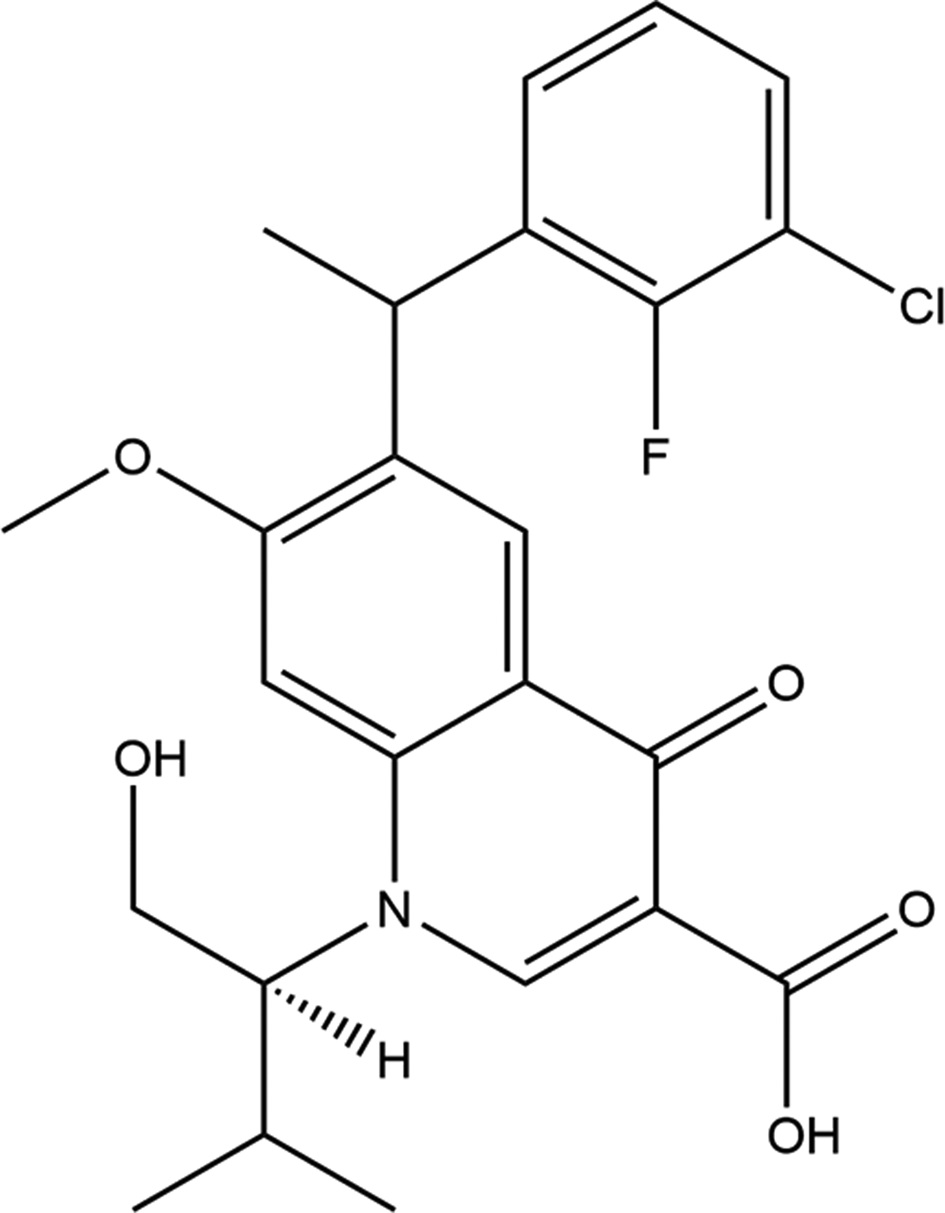
Elvitegravir is a modified quinolone antibiotic with activity against human immunodeficiency virus 1. Elvitegravir is an inhibitor of the enzyme viral integrase and retains activity against integrase mutants that are resistant to Raltegravir (PubChem; Kim et al., Reference Kim, Chen, Cheng, Gindulyte, He, He, Li, Shoemaker, Thiessen, Yu, Zaslavsky, Zhang and Bolton2019). It was developed by the pharmaceutical company Gilead Sciences, which licensed it from Japan Tobacco in March 2008. The drug gained approval by the U.S. Food and Drug Administration on August 27, 2012 for use in adult patients starting HIV treatment for the first time as part of the fixed-dose combination known as Stribild. On September 24, 2014, the FDA approved elvitegravir as a single pill formulation under the trade name Vitekta. On November 5, 2015, the FDA approved the drug for use in patients affected with HIV-1 as a part of a second fixed-dose combination pill known as Genvoya. The systematic name (CAS Registry Number 697761-98-1) is 6-[(3-chloro-2-fluorophenyl)methyl]-1-[(2S)-1-hydroxy-3-methylbutan-2-yl]-7-methoxy-4-oxoquinoline-3-carboxylic acid. A two-dimensional molecular diagram is shown in Figure 1.
The 2D molecular structure of elvitegravir.
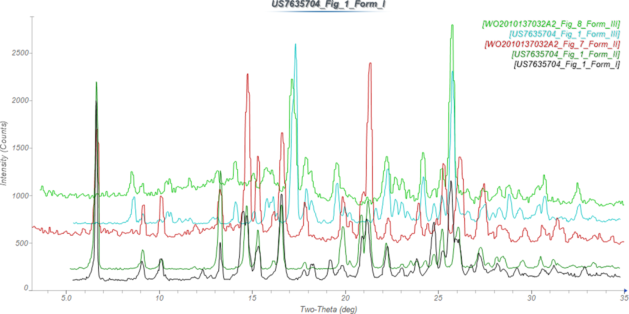
Elvitegravir and many similar compounds are claimed in US Patent 7,176,220 B2 (Satoh et al., Reference Satoh, Kawakami, Itoh, Shinkai, Motomura, Aramaki, Matsuzaki, Watanabe and Wamaki2007; Japan Tobacco Inc.), but no X-ray powder diffraction data were provided. Crystalline Forms I, II, and I of elvitegravir are claimed in US Patent 7,635,704 B2 (Satoh et al., Reference Satoh, Motomura, Matsuda, Kondo, Ando, Matsuda, Miyake and Uehara2009; Japan Tobacco Inc.), and XRD data are reported. Powder data for Forms II and III of elvitegravir, as well as for the amorphous form and amorphous and crystalline sodium salts, are reported in Vellanki et al. (Reference Vellanki, Dhake, Ravi, Nuchu and Puliyala2010; Matrix Laboratories Ltd.). Both Form II and Form III from both Japan Tobacco and Matrix seem to represent the same respective polymorphs (Figure 2).
Comparison of the X-ray powder diffraction patterns of elvitegravir Forms I, II, and III from Satoh et al. (Reference Satoh, Motomura, Matsuda, Kondo, Ando, Matsuda, Miyake and Uehara2009) and Vellanki et al. (Reference Vellanki, Dhake, Ravi, Nuchu and Puliyala2010). The patterns were digitized using UN-SCAN-IT (Silk Scientific, 2013). Image generated using JADE Pro (MDI, 2022).
This work was carried out as part of a project (Kaduk et al., Reference Kaduk, Crowder, Zhong, Fawcett and Suchomel2014) to determine the crystal structures of large-volume commercial pharmaceuticals, and include high-quality powder diffraction data for them in the Powder Diffraction File (Gates-Rector and Blanton, Reference Gates-Rector and Blanton2019).
II. EXPERIMENTAL AND REFINEMENTS
Elvitegravir was a commercial reagent, purchased from TargetMol (Lot #130053), and was used as-received. The white powder was packed into a 1.5 mm diameter Kapton capillary and rotated during the measurement at ~50 Hz. The powder pattern was measured at 295 K at beamline 11-BM (Antao et al., Reference Antao, Hassan, Wang, Lee and Toby2008; Lee et al., Reference Lee, Shu, Ramanathan, Preissner, Wang, Beno, Von Dreele, Ribaud, Kurtz, Antao, Jiao and Toby2008; Wang et al., Reference Wang, Toby, Lee, Ribaud, Antao, Kurtz, Ramanathan, Von Dreele and Beno2008) of the Advanced Photon Source at Argonne National Laboratory using a wavelength of 0.458208(2) Å from 0.5 to 50° 2θ with a step size of 0.001° and a counting time of 0.1 s step−1. The high-resolution powder diffraction data were collected using twelve silicon crystal analyzers that allow for high angular resolution, high precision, and accurate peak positions. A mixture of silicon (NIST SRM 640c) and alumina (NIST SRM 676a) standards (ratio Al2O3:Si = 2:1 by weight) was used to calibrate the instrument and refine the monochromatic wavelength used in the experiment.
The pattern was indexed using N-TREOR (Altomare et al., Reference Altomare, Cuocci, Giacovazzo, Moliterni, Rizzi, Corriero and Falcicchio2013) and DICVOL06 (Louër and Boultif, Reference Louër and Boultif2007) as incorporated into FOX (Favre-Nicolin and Černý, Reference Favre-Nicolin and Černý2002) on a primitive orthorhombic cell with a = 11.54903, b = 13.33241, c = 14.04233 Å, V = 2162.2 Å3, and Z = 4. A reduced cell search in the Cambridge Structural Database (Groom et al., Reference Groom, Bruno, Lightfoot and Ward2016) combined with the chemistry C, H, Cl, F, N, and O only yielded no hits. The space group was ambiguous, but P21221 yielded an apparent successful solution and refinement of the structure. An elvitegravir molecule was downloaded from PubChem (Kim et al., Reference Kim, Chen, Cheng, Gindulyte, He, He, Li, Shoemaker, Thiessen, Yu, Zaslavsky, Zhang and Bolton2019) as Conformer3D_CID_5277135.sdf. It was converted to a *.mol2 file using Mercury (Macrae et al., Reference Macrae, Sovago, Cottrell, Galek, McCabe, Pidcock, Platings, Shields, Stevens, Towler and Wood2020). The structure was solved by Monte Carlo simulated annealing as implemented in DASH (David et al., Reference David, Shankland, van de Streek, Pidcock, Samuel Motherwell and Cole2006). The success rate was ~30%.
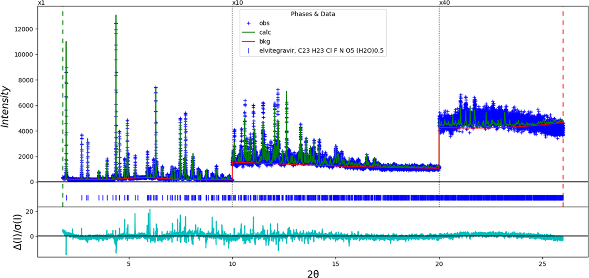
The structure solution contained a void on a twofold axis, indicated by Mercury with a probe radius of 1.2 Å. The void was located in a reasonable position to form hydrogen bonds, so a water molecule was added to the model. A Rietveld refinement of 117 variables using 24 238 observations and 81 restraints yielded the residuals R wp = 0.1399 and GOF = 2.14. The largest errors in the difference plot (Figure 3) were in the intensities of many of the strong low-angle peaks, and the fit was overall disappointing. The root-mean-square (rms) Cartesian displacement between the Rietveld-refined and DFT-optimized structures was 0.341 Å (Figure 4), at the upper end of the normal range for correct structures. The space group did not account for the weak (0.6% relative intensity) 1 0 0 peak at 2.27°. While no individual measure of the quality of the fit is necessarily a “red flag”, their sum motivated concern about the correctness of the structure.
The Rietveld plot for the refinement of the incorrect orthorhombic structure of elvitegravir. The blue crosses represent the observed data points, and the green line is the calculated pattern. The cyan curve is the normalized error plot, and the red curve indicates the background. The vertical scale has been multiplied by a factor of 10× for 2θ > 10.0° and by a factor of 40× for 2θ > 20.0°. The row of blue tick marks indicates the calculated reflection positions.
Comparison of the Rietveld-refined (red) and VASP-optimized (blue) structures of elvitegravir in the incorrect orthorhombic model. The rms Cartesian displacement is 0.326 Å. Image generated using Mercury (Macrae et al., Reference Macrae, Sovago, Cottrell, Galek, McCabe, Pidcock, Platings, Shields, Stevens, Towler and Wood2020).

Accordingly, the symmetry was lowered to P21 (to model the 1 0 0 peak), with a re-labeling of the axes to obtain the standard setting. This means that there are two molecules in the asymmetric unit, and thus, the problem is twice as large. The structure was re-solved in P21 using DASH, and the success rate was reduced to ~2%. (The success rate in a Monte Carlo simulated annealing run tends to decrease as the number of variables increases.) Thermogravimetic analysis (TGA) confirmed that the sample was anhydrous.
Rietveld refinement was carried out using GSAS-II (Toby and Von Dreele, Reference Toby and Von Dreele2013). Only the 1.9–24.0° portion of the pattern was included in the refinement (d min = 1.102 Å). The y-coordinate of Cl1 was fixed to define the origin. There was apparently a void in the structure (Figure 5). Including an O atom (water molecule) in this void resulted in a negative occupancy, so the atom was removed. All non-H bond distances and angles (plus the planes of ring systems) were subjected to restraints, based on a Mercury/Mogul Geometry Check (Bruno et al., Reference Bruno, Cole, Kessler, Luo, Sam Motherwell, Purkis, Smith, Taylor, Cooper, Harris and Guy Orpen2004; Sykes et al., Reference Sykes, McCabe, Allen, Battle, Bruno and Wood2011). The Mogul average and standard deviation for each quantity were used as the restraint parameters. The restraints contributed 9.8% to the final χ 2. The hydrogen atoms were included in calculated positions, which were recalculated during the refinement using Materials Studio (Dassault, 2021). The U iso of the heavy atoms were grouped by chemical similarity. The U iso for the H atoms were fixed at 1.3× the U iso of the heavy atoms to which they are attached. A second-order spherical harmonic preferred orientation model was included in the refinement. The refined texture index was 1.001(0). The peak profiles were described using the generalized microstrain model. The background was modeled using a 6-term shifted Chebyshev polynomial, and a peak at 5.79° 2θ to model the scattering from the Kapton capillary and any amorphous component.
The apparent void in the initial structure solution of the monoclinic model of elvitegravir (probe radius = 1.2 Å). Image generated using Mercury (Macrae et al., Reference Macrae, Sovago, Cottrell, Galek, McCabe, Pidcock, Platings, Shields, Stevens, Towler and Wood2020).

The final refinement of 216 variables using 22 135 observations and 166 restraints yielded the residuals R wp = 0.0897 and GOF = 1.39. The largest peak (0.11 Å from Cl1) and hole (0.92 Å from C64) in the difference Fourier map were 0.40(7) and −0.27(7) eÅ−3, respectively. The largest errors in the difference plot (Figure 6) are in the shapes of some of the strong peaks and in the background, but the refinement is much more satisfactory than the first refinement.
The Rietveld plot for the refinement of the correct monoclinic structure of elvitegravir. The blue crosses represent the observed data points, and the green line is the calculated pattern. The cyan curve is the normalized error plot, and the red curve indicates the background. The vertical scale has been multiplied by a factor of 10× for 2θ > 10.0° and by a factor of 40× for 2θ > 20.0°. The row of blue tick marks indicates the calculated reflection positions.

The crystal structures were optimized using VASP (Kresse and Furthmüller, Reference Kresse and Furthmüller1996) (fixed experimental unit cell) through the MedeA graphical interface (Materials Design, 2016). The calculation was carried out on 16 2.4 GHz processors (each with 4 GB RAM) of a 64-processor HP Proliant DL580 Generation 7 Linux cluster at North Central College. The calculation used the GGA-PBE functional, a plane wave cutoff energy of 400.0 eV, and a k-point spacing of 0.5 Å−1 leading to a 2 × 1 × 1 mesh, and took ~28.6 h. A single-point density functional calculation (fixed experimental cell) and population analysis were carried out using CRYSTAL17 (Dovesi et al., Reference Dovesi, Erba, Orlando, Zicovich-Wilson, Civalleri, Maschio, Rérat, Casassa, Baima, Salustro and Kirtman2018). The basis sets for the H, C, N, and O atoms in the calculation were those of Gatti et al. (Reference Gatti, Saunders and Roetti1994), and those for F and Cl were those of Peintinger et al. (Reference Peintinger, Oliveira and Bredow2013). The calculations were run on a 3.5 GHz PC using 8 k-points and the B3LYP functional, and took ~7.1 h. The monoclinic structure was 14.1 kcal mol−1 lower in energy than the orthorhombic model.
III. RESULTS AND DISCUSSION
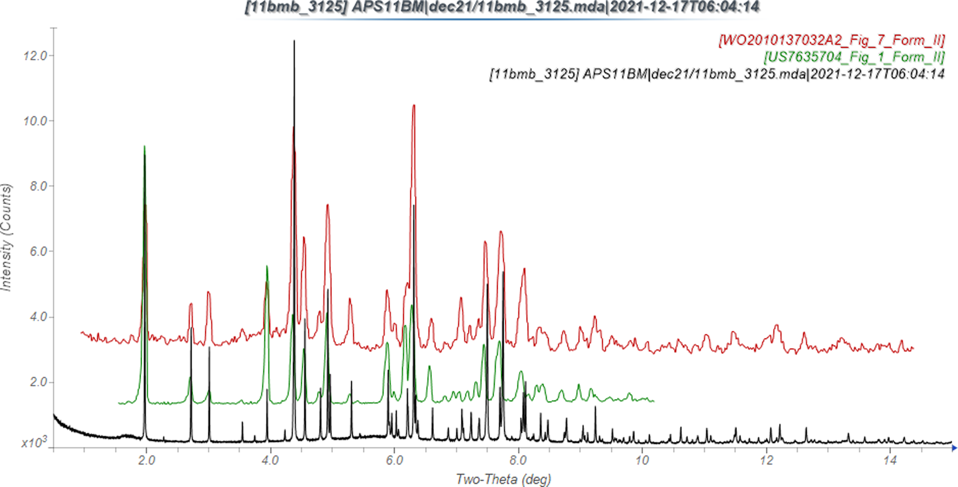
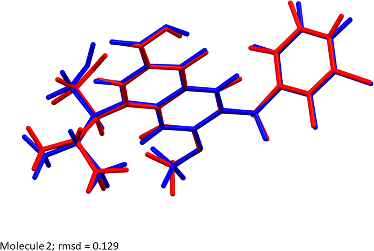
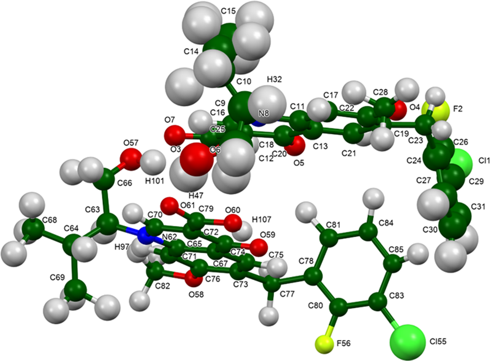
The synchrotron powder pattern of this study matches the patterns for Form II reported by Japan Tobacco (Satoh et al., Reference Satoh, Motomura, Matsuda, Kondo, Ando, Matsuda, Miyake and Uehara2009) and Matrix (Vellanki et al., Reference Vellanki, Dhake, Ravi, Nuchu and Puliyala2010) well enough to conclude that our sample is elvitegravir Form II (Figure 7). The rms Cartesian displacements between the Rietveld-refined and DFT-optimized structures of elvitegravir are 0.204 and 0.129 Å for molecules 1 (lower atom numbers) and 2 (Figures 8 and 9). The good agreement provides evidence that the structure is correct (van de Streek and Neumann, Reference van de Streek and Neumann2014). The apparent void disappeared in the DFT-optimized structure. This discussion concentrates on the DFT-optimized structure. The asymmetric unit (with atom numbering) is illustrated in Figure 10. The displacement coefficients of the atoms in the isopropyl group of molecule 1 are larger than those of the other atoms, suggesting the possibility of some disorder of this group. The two independent elvitegravir molecules are similar (Figure 11), but exhibit many differences, especially in the methyl groups. The rms Cartesian displacement between the two molecules is 0.582 Å.
Comparison of the synchrotron pattern of elvitegravir (black) to that reported by Satoh et al. (Reference Satoh, Motomura, Matsuda, Kondo, Ando, Matsuda, Miyake and Uehara2009; green) and Vellanki et al. (Reference Vellanki, Dhake, Ravi, Nuchu and Puliyala2010; red). The literature patterns, measured using CuKα radiation, were digitized using UN-SCAN-IT (Silk Scientific, 2013) and converted to the synchrotron wavelength of 0.458208 Å using JADE Pro (MDI, 2022). Image generated using JADE Pro (MDI, 2022).
Comparison of the Rietveld-refined (red) and VASP-optimized (blue) structures of molecule 1 of elvitegravir. The rms Cartesian displacement is 0.204 Å. Image generated using Mercury (Macrae et al., Reference Macrae, Sovago, Cottrell, Galek, McCabe, Pidcock, Platings, Shields, Stevens, Towler and Wood2020).

Comparison of the Rietveld-refined (red) and VASP-optimized (blue) structures of molecule 2 of elvitegravir. The rms Cartesian displacement is 0.129 Å. Image generated using Mercury (Macrae et al., Reference Macrae, Sovago, Cottrell, Galek, McCabe, Pidcock, Platings, Shields, Stevens, Towler and Wood2020).
The asymmetric unit of elvitegravir, with the atom numbering. The atoms are represented by 50% probability spheroids. Image generated using Mercury (Macrae et al., Reference Macrae, Sovago, Cottrell, Galek, McCabe, Pidcock, Platings, Shields, Stevens, Towler and Wood2020).
Comparison of molecule 1 (green) and molecule 2 (purple) of elvitegravir. The rms Cartesian displacement is 0.582 Å. Image generated using Mercury (Macrae et al., Reference Macrae, Sovago, Cottrell, Galek, McCabe, Pidcock, Platings, Shields, Stevens, Towler and Wood2020).

The crystal structure (Figures 12 and 13) consists of alternating layers of parallel molecules perpendicular to the b-axis. The mean planes of the oxoquinoline ring systems in molecules 1 and 2 are 1(22)-1 and -1(22)1. Between the stacks are layers of the halogenated phenyl rings. These exhibit herringbone stacking. Although the general arrangements of the molecules in the correct and incorrect structures are similar (Figure 14), there are many subtle differences.
The crystal structure of elvitegravir, viewed down the a-axis. Image generated using Diamond (Crystal Impact, 2022).
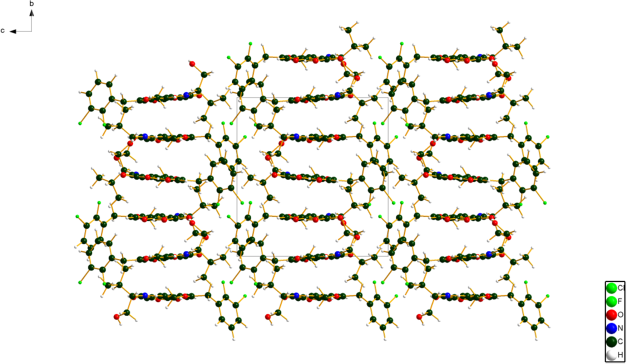
The crystal structure of elvitegravir, viewed down the b-axis. Image generated using Diamond (Crystal Impact, 2022).

Comparison of the correct monoclinic (left) and incorrect orthorhombic (right) structures of elvitegravir. Image generated using Materials Studio (Dassault, 2021).

Almost all of the bond distances, bond angles, and torsion angles fall within the normal ranges indicated by a Mercury/Mogul Geometry check (Macrae et al., Reference Macrae, Sovago, Cottrell, Galek, McCabe, Pidcock, Platings, Shields, Stevens, Towler and Wood2020). The C63–N62 distance of 1.495 Å (average = 1.469(7) Å, Z-score = 3.4) is flagged as unusual. The uncertainty on this average is exceptionally small, inflating the Z-score. The C10–C9–N8–C11 torsion angle is flagged as unusual. This lies within a broad distribution of a small number of similar torsion angles, and is not of concern. The torsion angles involving rotation about the C19–C23 bond lie on the tails of distributions which peak around 90°. These angles lie in the linkage between the two ring systems, and indicate that the conformation of the molecule is slightly unusual.
The quantum chemical geometry optimization of the elvitegravir molecules (DFT/B3LYP/6-31G*/water) using Spartan ‘18 (Wavefunction, 2020) indicated that the observed solid-state conformations are comparable in energy. The conformational differences are small and spread throughout the molecules. A conformational analysis (MMFF force field) indicates that the global minimum-energy conformation has a similar general shape to the observed conformations, but with many small differences. The rms Cartesian displacements between molecules 1 and 2 and the global minimum-energy conformation are 1.259 and 1.270 Å, respectively. Notably, the orientation of the carboxylic acid group differs in the global minimum; it does not form the intramolecular hydrogen bonds observed in the solid state.
Analysis of the contributions to the total crystal energy of the structure using the Forcite module of Materials Studio (Dassault, 2021) suggests that bond, angle, and torsion distortion terms are about equally important in the intramolecular deformation energy. The intermolecular energy is dominated by van der Waals repulsions and electrostatic attractions, which in this force field analysis include hydrogen bonds. The hydrogen bonds are better analyzed using the results of the DFT calculation.
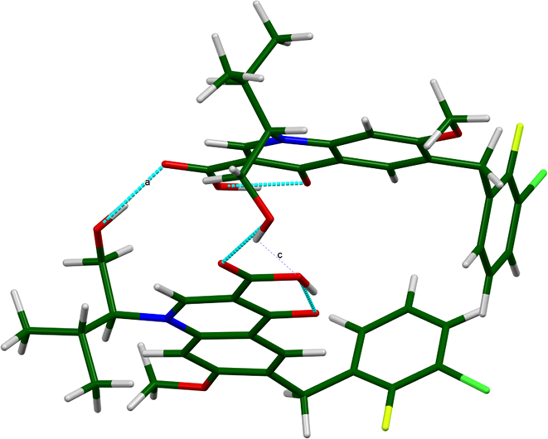
In each molecule, the carboxylic acid group forms a strong intramolecular O–H⋯O hydrogen bond to the nearby carbonyl group (Table I). The energies of the O–H⋯O hydrogen bonds were calculated using the correlation of Rammohan and Kaduk (Reference Rammohan and Kaduk2018). The hydroxyl group of each molecule forms a strong hydrogen bond to the carbonyl group of the carboxylic acid of the other molecule. These O–H⋯O hydrogen bonds link the molecules into dimers, with a graph set (Etter, Reference Etter1990; Bernstein et al., Reference Bernstein, Davis, Shimoni and Chang1995; Shields et al., Reference Shields, Raithby, Allen and Samuel Motherwell2000) R2,2(18)>a > c (Figure 15). In each molecule, two aromatic C–H form intramolecular hydrogen bonds to carbonyl O atoms. There are subtle differences among the C–H⋯O and C–H⋯Cl hydrogen bonds in the two molecules.
The dimers of elvitegravir, linked by O–H⋯O hydrogen bonds. Image generated using Mercury (Macrae et al., Reference Macrae, Sovago, Cottrell, Galek, McCabe, Pidcock, Platings, Shields, Stevens, Towler and Wood2020).
Hydrogen bonds (CRYSTAL17) in elvitegravir.

Top line = molecule 1, and bottom line = molecule 2.
a Intramolecular.
The volume enclosed by the Hirshfeld surface of elvitegravir (Figure 16; Hirshfeld, Reference Hirshfeld1977; Turner et al., Reference Turner, McKinnon, Wolff, Grimwood, Spackman, Jayatilaka and Spackman2017) is 1070.74 Å3, 99.03% of 1/2 the unit cell volume. The packing density is thus fairly typical. The only significant close contacts (red in Figure 16) involve the hydrogen bonds. The volume/non-hydrogen atom is typical at 16.9 Å3.
The Hirshfeld surface of elvitegravir. Intermolecular contacts longer than the sums of the van der Waals radii are colored blue, and contacts shorter than the sums of the radii are colored red. Contacts equal to the sums of radii are white. Image generated using CrystalExplorer (Turner et al., Reference Turner, McKinnon, Wolff, Grimwood, Spackman, Jayatilaka and Spackman2017).

The Bravais–Friedel–Donnay–Harker (Bravais, Reference Bravais1866; Friedel, Reference Friedel1907; Donnay and Harker, Reference Donnay and Harker1937) morphology suggests that we might expect blocky morphology for elvitegravir. A second-order spherical harmonic preferred orientation model was included in the refinement. The texture index was 1.001(0), indicating that preferred orientation was not significant for this rotated capillary specimen.
IV. DEPOSITED DATA
The powder pattern of elvitegravir from this synchrotron data set has been submitted to ICDD for inclusion in the Powder Diffraction File. The Crystallographic Information Framework (CIF) files containing the results of the Rietveld refinement (including the raw data) and the DFT geometry optimization were deposited with the ICDD. The data can be requested at pdj@icdd.com.
ACKNOWLEDGEMENTS
The use of the Advanced Photon Source at Argonne National Laboratory was supported by the U.S. Department of Energy, Office of Science, Office of Basic Energy Sciences, under Contract No. DE-AC02-06CH11357. This work was partially supported by the International Centre for Diffraction Data. We thank Lynn Ribaud and Saul Lapidus for their assistance in the data collection, and Rebecca Sanders of North Central College for the TGA analysis.
CONFLICT OF INTEREST
The authors have no conflict of interest to declare.


 Open access

