





Nomenclature
- MAV
-
micro air vehicles
- NACA
-
National Advisory Committee for Aeronautics
- NASA
-
National Aeronautics and Space Administration
- PIV
-
particle image velocimetry
- SLE
-
sinusoidal leading-edge
- UCAV
-
unmanned combat air vehicles
- UAV
-
unmanned aerial vehicle
- $A$
$A$
-
reference area
-
$C$
-
chord
-
${C_D}$
-
drag coefficient
-
${C_L}/{C_D}$
-
lift-to-drag ratio
-
${C_L}$
-
lift coefficient
-
${C_{L\;{\rm{max}}}}$
-
maximum lift coefficient
-
${C_M}$
-
pitching moment coefficient
-
${C_{M\;at\;TE}}$
-
moment coefficient at the trailing edge
-
${C_p}$
-
surface pressure coefficient
-
${F_D}$
-
drag force
-
${F_L}$
-
lift force
-
$L$
-
reference length
-
${P_{dyn}}$
-
dynamic pressure of the freestream
-
${P_m}$
-
mean pressure
-
${P_\infty }$
-
static pressure of the freestream
- Re
-
Reynolds number
- S
-
span
- t
-
thickness
-
${U_\infty }$
-
free stream velocity
-
$x/C$
-
chordwise distance


Greek symbol
-
$\alpha $
-
angle-of-attack
-
$\varLambda $
-
sweep angle
-
$\rho $
-
density
-
$\phi /{\rm{C}}$
-
amplitude ratio
-
${\rm{\lambda }}/{\rm{C}}$
-
wavelength ratio


1.0 Introduction
Delta wings are commonly used on unmanned aerial vehicles (UAV), micro air vehicles (MAV), and unmanned combat air vehicles (UCAV) due to their ability to maintain attached flow on the wing surface at high angles of attack, which, as a result, enhances the lift coefficient and delays stall [Reference Gupta, Kumar and Kumar9, Reference Ramakrishna, Senthil Kumar and Venkatesh26]. In recent years, there has been an increased demand for these aerial vehicles in the civilian and military sectors. This heightened interest increased the popularity of research on the flow control of delta wings.
Delta wings are classified into two categories according to their sweep angles ( $\varLambda $
): slender (
$\varLambda $
): slender ( $\varLambda \gt 55^\circ $
) and non-slender (
$\varLambda \gt 55^\circ $
) and non-slender ( $\varLambda \lt 55^\circ $
) delta wings [Reference Gursul, Cleaver and Wang11]. In non-slender delta wings, a dual primary vortex structure is generated due to the proximity of the vortex formation to the wing surface [Reference Gursul10, Reference Gursul, Gordnier and Visbal12]. Extensive studies have been conducted to improve the aerodynamic performance of these wings with passive and active flow control methods. Bio-inspired structures such as leading-edge serrations, riblets, surface topography, grooves, vortex generators, such as needle-shaped vortex generators, and leading-edge tubercles are studied by many researchers as passive flow control methods [Reference Naeini, Nili-Ahmadabadi, Park and Kim23, Reference Rose, Natarajan and Gopinathan28, Reference Shahsavari, Nili-Ahmadabadi, Aslani and Kim29].
$\varLambda \lt 55^\circ $
) delta wings [Reference Gursul, Cleaver and Wang11]. In non-slender delta wings, a dual primary vortex structure is generated due to the proximity of the vortex formation to the wing surface [Reference Gursul10, Reference Gursul, Gordnier and Visbal12]. Extensive studies have been conducted to improve the aerodynamic performance of these wings with passive and active flow control methods. Bio-inspired structures such as leading-edge serrations, riblets, surface topography, grooves, vortex generators, such as needle-shaped vortex generators, and leading-edge tubercles are studied by many researchers as passive flow control methods [Reference Naeini, Nili-Ahmadabadi, Park and Kim23, Reference Rose, Natarajan and Gopinathan28, Reference Shahsavari, Nili-Ahmadabadi, Aslani and Kim29].
Otto Lilienthal [Reference Lilienthal17] conducted one of aviation’s earliest and most influential studies on biomimicry. In his research, he mimicked various wing shapes and movements of different bird species to make human flight possible. Many researchers [Reference Lee, Kim, Park, Jabłoński and Choi16, Reference Naeini, Nili-Ahmadabadi, Park and Kim23, Reference Rao and Liu27, Reference Shahsavari, Nili-Ahmadabadi, Aslani and Kim29] and engineers followed the same path and researched avians to design or improve aerial vehicles. However, avians are just one source of inspiration for aerodynamics research. Structures from aquatic animals, insects and even plants can be utilised to improve aerodynamic performance [Reference Rose, Natarajan and Gopinathan28].
Recently, marine animals have received attention from researchers. These researchers have investigated the effects of various marine animal structures, such as fish scales, skin topography, and leading-edge tubercles, to decrease drag, delay transition, and improve aerodynamic efficiency [Reference Anders1, Reference Domel, Saadat, Weaver, Haj-Hariri, Bertoldi and Lauder5, Reference Muthuramalingam, Villemin and Bruecker22].
Among these structures, the tubercles of humpback whales have particular importance, since these structures serve as vortex generators and improve the whale’s manoeuverability in the water [Reference Fish, Weber, Murray and Howle6, Reference Miklosovic, Murray, Howle and Fish20, Reference Post, Decker, Sapell and Hart25, Reference Yoon, Hung, Jung and Kim31]. Most of the studies investigating the effects of these structures study the effect of the sinusoidal leading edge (SLE) on aerofoils, while a few investigate the effects of SLE on delta wings. These studies mainly focused on the effect of amplitude and wavelength on the aerodynamic or hydrodynamic performance of SLE models. Other researchers studied the effect of sinusoidal leading-edge modifications with visualisation methods such as particle image velocimetry (PIV) [Reference Chen and Wang4, Reference Goruney and Rockwell7], tuft flow visualisation [Reference Johari, Henoch, Custodio and Levshin14], hydrogen-bubble visualisation [Reference Chen, Pan and Wang3], and surface oil-flow visualisation [Reference Chen, Pan and Wang3, Reference Post, Decker, Sapell and Hart25, Reference Zverkov, Zanin and Kozlov33].
Johari et al. [Reference Johari, Henoch, Custodio and Levshin14] were among the first research groups to focus on aerofoils with sinusoidal leading-edge modifications inspired by humpback whale tubercles. They conducted force measurements and the tuft flow visualisation method to investigate the effects of SLE modifications on the aerodynamic performance and flow characteristics of a NACA 634-021 aerofoil. The results of this study showed that the aerofoils with SLE modifications did not exhibit similar stall characteristics compared to the baseline aerofoil. Moreover, the results showed that the poststall lift coefficients were approximately 1.5 times higher when SLE modifications were utilised. Guerreiro and Sousa [Reference Guerreiro and Sousa8] investigated the aerodynamic performance of the NASA LS(I)-0417 profile with SLE modifications at Reynolds numbers of $Re = 0.7 \times {10^5}$
and
$Re = 0.7 \times {10^5}$
and $Re = 1.4 \times {10^5}$
. The results of this study indicated that the wings with SLE modifications are less prone to performance deterioration due to variation in Reynolds number than wings with no modifications [Reference Guerreiro and Sousa8]. Hansen et al. [Reference Hansen, Kelso and Dally13] studied the effect of SLE on a NACA 0021 aerofoil without any sweep or taper and compared two-dimensional and three-dimensional models of this aerofoil at
$Re = 1.4 \times {10^5}$
. The results of this study indicated that the wings with SLE modifications are less prone to performance deterioration due to variation in Reynolds number than wings with no modifications [Reference Guerreiro and Sousa8]. Hansen et al. [Reference Hansen, Kelso and Dally13] studied the effect of SLE on a NACA 0021 aerofoil without any sweep or taper and compared two-dimensional and three-dimensional models of this aerofoil at $Re = 1.2 \times {10^5}$
. This study indicated that the presence of tubercles had insignificant effects on the formation of the wing-tip vortices. The smallest amplitude and smallest wavelength configuration of tubercles performed the best for both two-dimensional and three-dimensional cases [Reference Hansen, Kelso and Dally13]. Van Nierop et al. [Reference van Nierop, Alben and Brenner30] experimentally studied the SLE modifications on a swept wing. The maximum lift coefficient of the SLE wing models was observed to be higher than that of the base wing in the post-stall regime. Furthermore, for wing models with lower amplitude perturbations, the transition to stall occurs more gradually compared to the base wing model.
$Re = 1.2 \times {10^5}$
. This study indicated that the presence of tubercles had insignificant effects on the formation of the wing-tip vortices. The smallest amplitude and smallest wavelength configuration of tubercles performed the best for both two-dimensional and three-dimensional cases [Reference Hansen, Kelso and Dally13]. Van Nierop et al. [Reference van Nierop, Alben and Brenner30] experimentally studied the SLE modifications on a swept wing. The maximum lift coefficient of the SLE wing models was observed to be higher than that of the base wing in the post-stall regime. Furthermore, for wing models with lower amplitude perturbations, the transition to stall occurs more gradually compared to the base wing model.
Yoon et al. [Reference Yoon, Hung, Jung and Kim31] numerically studied the hydrodynamic characteristics of SLE modifications on the NACA 0020 aerofoil with various waviness ratios at $Re = 2 \times {10^6}$
. The results of this study showed that as the waviness increases, the stall occurs earlier than that of the base model. However, the wings with SLE modifications had a higher lift coefficient in the post-stall region. Furthermore, it was observed that irrespective of the waviness ratio, the effect of SLE modifications on the flow structure was insignificant for the lower angles of attack (
$Re = 2 \times {10^6}$
. The results of this study showed that as the waviness increases, the stall occurs earlier than that of the base model. However, the wings with SLE modifications had a higher lift coefficient in the post-stall region. Furthermore, it was observed that irrespective of the waviness ratio, the effect of SLE modifications on the flow structure was insignificant for the lower angles of attack ( $0^\circ \le \alpha \le 12^\circ $
) [Reference Yoon, Hung, Jung and Kim31]. Kim et al. [Reference Kim, Yoon, Jung, Chun and Park15] conducted similar research with Yoon et al. and reached the same verdict. Zhao et al. [Reference Zhao, Wei, Zhao and Liu32] conducted a large eddy simulation (LES) on a NACA 0021 aerofoil with and without SLE modifications and studied the effect of amplitude on the flow structure at
$0^\circ \le \alpha \le 12^\circ $
) [Reference Yoon, Hung, Jung and Kim31]. Kim et al. [Reference Kim, Yoon, Jung, Chun and Park15] conducted similar research with Yoon et al. and reached the same verdict. Zhao et al. [Reference Zhao, Wei, Zhao and Liu32] conducted a large eddy simulation (LES) on a NACA 0021 aerofoil with and without SLE modifications and studied the effect of amplitude on the flow structure at $Re = 1.2 \times {10^6}$
. The results of his study indicated that the flow separation was delayed and the aerodynamic performance was improved for large amplitudes due to the separation bubbles caused by the turbulent mixing. Moscato et al. [Reference Moscato, Mohamed and Romano21] conducted a numerical study to investigate the effects of SLE modifications on force coefficients, flow fields, turbulence production and flow reattachment. This study showed that using SLE modifications increased the maximum lift coefficient by approximately 20%, delayed the stall angle up to
$Re = 1.2 \times {10^6}$
. The results of his study indicated that the flow separation was delayed and the aerodynamic performance was improved for large amplitudes due to the separation bubbles caused by the turbulent mixing. Moscato et al. [Reference Moscato, Mohamed and Romano21] conducted a numerical study to investigate the effects of SLE modifications on force coefficients, flow fields, turbulence production and flow reattachment. This study showed that using SLE modifications increased the maximum lift coefficient by approximately 20%, delayed the stall angle up to $4^\circ $
, provided smoother post and pre-stall behaviour, reduced the level of turbulence production and prevented separation and backflow on the wing’s upper surface. Moreover, the post-stall behaviour was smoother than the unmodified wing [Reference Moscato, Mohamed and Romano21]. Ramakrishna et al. [Reference Ramakrishna, Senthil Kumar and Venkatesh26] compared the effects of leading-edge design on a delta wing with a sweep angle of
$4^\circ $
, provided smoother post and pre-stall behaviour, reduced the level of turbulence production and prevented separation and backflow on the wing’s upper surface. Moreover, the post-stall behaviour was smoother than the unmodified wing [Reference Moscato, Mohamed and Romano21]. Ramakrishna et al. [Reference Ramakrishna, Senthil Kumar and Venkatesh26] compared the effects of leading-edge design on a delta wing with a sweep angle of $\varLambda = 65^\circ $
. Three different leading-edge designs were used: plane delta wing, with no modifications, saw-tooth delta wing, and sinusoidal delta wing. The results showed that the saw-tooth wing model delayed stall more than the SLE wing models [Reference Ramakrishna, Senthil Kumar and Venkatesh26]. Lift coefficients for all the wing models were not significantly affected by variations in the Reynolds number. Moreover, the lift-to-drag ratio of the saw-tooth model was higher than other models. The sinusoidal wing model performed better than the plane wing regarding the lift-to-drag ratio, but did not exceed the saw-tooth wing model [Reference Ramakrishna, Senthil Kumar and Venkatesh26].
$\varLambda = 65^\circ $
. Three different leading-edge designs were used: plane delta wing, with no modifications, saw-tooth delta wing, and sinusoidal delta wing. The results showed that the saw-tooth wing model delayed stall more than the SLE wing models [Reference Ramakrishna, Senthil Kumar and Venkatesh26]. Lift coefficients for all the wing models were not significantly affected by variations in the Reynolds number. Moreover, the lift-to-drag ratio of the saw-tooth model was higher than other models. The sinusoidal wing model performed better than the plane wing regarding the lift-to-drag ratio, but did not exceed the saw-tooth wing model [Reference Ramakrishna, Senthil Kumar and Venkatesh26].
Chen et al. [Reference Chen, Pan and Wang3, Reference Chen and Wang4] investigated the effects of SLE modifications on a delta wing with a sweep angle of $\varLambda = 52^\circ $
. Nine different wing configurations were used to investigate multiple amplitudes and wavelengths. The force measurements showed results similar to those of Johari et al. [Reference Johari, Henoch, Custodio and Levshin14]. The results indicated that when the amplitude was increased above a critical value, the maximum lift coefficient decreased significantly, and the stall was delayed when SLE modifications were utilised [Reference Chen, Pan and Wang3, Reference Chen and Wang4]. Goruney and Rockwell [Reference Goruney and Rockwell7] investigated the near-surface flow patterns of an SLE delta wing with a sweep angle of
$\varLambda = 52^\circ $
. Nine different wing configurations were used to investigate multiple amplitudes and wavelengths. The force measurements showed results similar to those of Johari et al. [Reference Johari, Henoch, Custodio and Levshin14]. The results indicated that when the amplitude was increased above a critical value, the maximum lift coefficient decreased significantly, and the stall was delayed when SLE modifications were utilised [Reference Chen, Pan and Wang3, Reference Chen and Wang4]. Goruney and Rockwell [Reference Goruney and Rockwell7] investigated the near-surface flow patterns of an SLE delta wing with a sweep angle of $\varLambda = 50^\circ $
at a Reynolds number of
$\varLambda = 50^\circ $
at a Reynolds number of $Re = 1.5 \times {10^4}$
. The findings of this study showed that the focus of three-dimensional separation moved toward the leading edge as the amplitude of the SLE was increased. When the amplitude surpasses a critical point, the focus of three-dimensional separation is eliminated and replaced by a focus of attachment [Reference Goruney and Rockwell7].
$Re = 1.5 \times {10^4}$
. The findings of this study showed that the focus of three-dimensional separation moved toward the leading edge as the amplitude of the SLE was increased. When the amplitude surpasses a critical point, the focus of three-dimensional separation is eliminated and replaced by a focus of attachment [Reference Goruney and Rockwell7].
In the current study, the effect of bio-inspired leading-edge modifications on the flow structure over a non-slender delta wing with a sweep angle of $\varLambda = 45^\circ $
is studied experimentally at a Reynolds number of
$\varLambda = 45^\circ $
is studied experimentally at a Reynolds number of $Re = 1 \times {10^5}$
. Techniques such as force and surface pressure measurements were utilised over an angle-of-attack range from
$Re = 1 \times {10^5}$
. Techniques such as force and surface pressure measurements were utilised over an angle-of-attack range from $ - 4^\circ $
to
$ - 4^\circ $
to $30^\circ $
and
$30^\circ $
and $ - 2^\circ $
to
$ - 2^\circ $
to $30^\circ $
, respectively. Four sinusoidal and two saw-tooth leading-edge wing models with wavelength ratios from 0.1 to 0.3 and amplitude ratios from 0.02 to 0.05 were compared with a base wing model.
$30^\circ $
, respectively. Four sinusoidal and two saw-tooth leading-edge wing models with wavelength ratios from 0.1 to 0.3 and amplitude ratios from 0.02 to 0.05 were compared with a base wing model.
2.0 Experimental methods
Experiments were conducted in a low-speed, suction-type, open-circuit wind tunnel in the Fluid Mechanics Laboratory of the Mechanical Engineering Department at Middle East Technical University. The wind tunnel has five main parts: a settling chamber, a contraction cone, a test section, a diffuser and a fan. The wind tunnel has two symmetrical inlet sections at the sides, with fine mesh screens. The contraction cone has a 2000 mm length and a contraction ratio of 8:1. The test section, which has transparent walls, has a 750 mm width, 510 mm height and 2000 mm length. An axial fan with a 10kW AC motor is assembled at the exit of the wind tunnel with a remote control unit to control the velocity of the test section. The test section has a maximum freestream velocity of 20 m/s. The force and surface pressure measurements were performed at a Reynolds number of $Re = 1 \times {10^5}$
with a corresponding free stream velocity range of
$Re = 1 \times {10^5}$
with a corresponding free stream velocity range of $10.9 \le {U_\infty } \le 11.2$
. The maximum blockage ratio is lower than 3% at the highest angle-of-attack of
$10.9 \le {U_\infty } \le 11.2$
. The maximum blockage ratio is lower than 3% at the highest angle-of-attack of $\alpha = 30^\circ $
.
$\alpha = 30^\circ $
.
Seven different sharp-edged delta wing models were used with a 45-degree sweep angle ( $\varLambda $
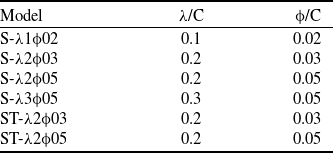
) and a single-sided bevel on the windward side at a 45-degree angle. Sinusoidal and saw-tooth leading-edge modifications were applied in the present study. The schematics and pictures of some of the wing models are shown in Fig. 1. The sinusoidal-leading-edge wing models were inspired by the tubercle structure of humpback whales, and saw-tooth leading-edge models were inspired by the studies of Ramakrishna et al. [Reference Ramakrishna, Senthil Kumar and Venkatesh26]. The wavelength and amplitude ratios of the wing models are given in Table 1. The ‘S’ and ‘ST’ notations in the names of the wing models represent sinusoidal and saw-tooth leading edges, respectively. The ‘λ’ symbol denotes the wavelength ratio, while the ‘φ’ symbol represents the amplitude ratio, and the numbers following these symbols indicate decimal values of ratios. The chord (
$\varLambda $
) and a single-sided bevel on the windward side at a 45-degree angle. Sinusoidal and saw-tooth leading-edge modifications were applied in the present study. The schematics and pictures of some of the wing models are shown in Fig. 1. The sinusoidal-leading-edge wing models were inspired by the tubercle structure of humpback whales, and saw-tooth leading-edge models were inspired by the studies of Ramakrishna et al. [Reference Ramakrishna, Senthil Kumar and Venkatesh26]. The wavelength and amplitude ratios of the wing models are given in Table 1. The ‘S’ and ‘ST’ notations in the names of the wing models represent sinusoidal and saw-tooth leading edges, respectively. The ‘λ’ symbol denotes the wavelength ratio, while the ‘φ’ symbol represents the amplitude ratio, and the numbers following these symbols indicate decimal values of ratios. The chord ( ${\rm{C}}$
), the span (
${\rm{C}}$
), the span ( $S$
) and the thickness (
$S$
) and the thickness ( $t$
) of the delta wing models are 135, 270, and 8 mm, respectively. The surface area of each modified wing model is kept the same as that of the base wing. The delta wing models were designed to allow access to the pressure channels from the trailing edge. There are nine pressure channels in each half of the wing, eighteen pressure channels in total, at a chordwise distance of
$t$
) of the delta wing models are 135, 270, and 8 mm, respectively. The surface area of each modified wing model is kept the same as that of the base wing. The delta wing models were designed to allow access to the pressure channels from the trailing edge. There are nine pressure channels in each half of the wing, eighteen pressure channels in total, at a chordwise distance of $x/{\rm{C\;}} = {\rm{\;}}0.5$
for each wing model.
$x/{\rm{C\;}} = {\rm{\;}}0.5$
for each wing model.
Schematics and pictures of the base, sinusoidal leading-edge and saw-tooth leading-edge wing models.

The aerodynamic force measurements were performed using an ATI Gamma Series Force/Torque transducer calibrated according to the SI-32-2.5 scheme. The wing model is assembled to a strut that connects at its trailing edge, aligning it with the transducer’s y-axis, which acts as the pitch axis. The strut is connected to the sensor adaptor, and the sensor is rigidly connected to the model positioning system. The model positioning system is a traverse system that allows users to change the angle-of-attack of the wind model with a desired increment. The force measurements were performed over an angle-of-attack range of $ - 4^\circ $
to
$ - 4^\circ $
to $30^\circ $
. The drag and lift coefficients (
$30^\circ $
. The drag and lift coefficients ( ${C_D},{C_L}$
) and the pitch moment coefficient (
${C_D},{C_L}$
) and the pitch moment coefficient ( ${C_M}$
) were calculated using Equations (1) and (2), where the reference area (
${C_M}$
) were calculated using Equations (1) and (2), where the reference area ( $A$
) is 18,225 mm2, and the reference length (
$A$
) is 18,225 mm2, and the reference length ( $L$
) is equal to the wing chord length (
$L$
) is equal to the wing chord length ( ${\rm{C}}$
), which is 135 mm. Measurements were sampled with a National Instruments NI-PCIe-6321 16-bit data acquisition (DAQ) card at 10 kHz for 10 seconds for each measurement. Maximum absolute uncertainty values for lift coefficient (
${\rm{C}}$
), which is 135 mm. Measurements were sampled with a National Instruments NI-PCIe-6321 16-bit data acquisition (DAQ) card at 10 kHz for 10 seconds for each measurement. Maximum absolute uncertainty values for lift coefficient ( ${C_L}$
), drag coefficient (
${C_L}$
), drag coefficient ( ${C_D}$
), moment coefficient (
${C_D}$
), moment coefficient ( ${C_M}$
) and lift-to-drag ratio (
${C_M}$
) and lift-to-drag ratio ( ${C_D}/{C_L}$
) are estimated as
${C_D}/{C_L}$
) are estimated as $ \pm 0.05$
,
$ \pm 0.05$
, $ \pm 0.05$
, and
$ \pm 0.05$
, and $ \pm 0.06$
, respectively. A schematic view of the wind tunnel from the top and end view, with the force measurement setup, is given in Fig. 2.
$ \pm 0.06$
, respectively. A schematic view of the wind tunnel from the top and end view, with the force measurement setup, is given in Fig. 2.
 \begin{align} {C_D},{C_L} = \frac{{{F_D},{F_L}}}{{\dfrac{{\rho U_\infty ^2}}{2}A}} \end{align}
 \begin{align} {C_M} = \frac{{{M_y}}}{{\dfrac{{\rho U_\infty ^2}}{2}AL}} \end{align}
The aerodynamic and gravitational forces and moments of the bare strut are measured for each angle-of-attack to tare out the effects of the strut system.
Wavelength and amplitude ratios for sinusoidal and saw-tooth leading edge wings

Schematic representation of the top and end views of the force measurement system.

The surface pressure measurements were conducted on the suction side of all the wing models with a 16-channel Netscanner 9116 Intelligent Pressure Scanner. This scanner is capable of measuring pressures in the range of 0–2.5 kPa with 16 piezo-resistive transducers. The resolution of the pressure scanner is $ \pm 0.003\% $
FS (full scale), and the scanner’s accuracy is
$ \pm 0.003\% $
FS (full scale), and the scanner’s accuracy is $ \pm 0.05\% $
FS. The resolution of the pressure scanner is ensured with the microprocessor and temperature sensors, which are integrated into the pressure scanner to compensate for the thermal effects, nonlinearity, sensitivity and transducer outputs for offset.
$ \pm 0.05\% $
FS. The resolution of the pressure scanner is ensured with the microprocessor and temperature sensors, which are integrated into the pressure scanner to compensate for the thermal effects, nonlinearity, sensitivity and transducer outputs for offset.
The pressure data were collected over an angle-of-attack range of $ - 2^\circ $
to
$ - 2^\circ $
to $30^\circ $
and for 10 seconds at a sampling rate of 500 Hz. The pressure coefficient
$30^\circ $
and for 10 seconds at a sampling rate of 500 Hz. The pressure coefficient ${C_p}$
was calculated using Equation (3). The maximum absolute uncertainty value for the pressure coefficient (
${C_p}$
was calculated using Equation (3). The maximum absolute uncertainty value for the pressure coefficient ( ${C_p}$
) is estimated as 2.5%.
${C_p}$
) is estimated as 2.5%.
 \begin{align} {C_p} = \frac{{{P_m} - {P_\infty }}}{{\dfrac{{\rho U_\infty ^2}}{2}}} = \frac{{{P_m} - {P_\infty }}}{{{P_{dyn}}}} \end{align}
3.0 Results and discussion
In this study, force and surface pressure measurements were performed on seven wing models. Four of these wing models, the base wing, S-λ2φ03, S-λ2φ05 and ST-λ2φ05, were selected and presented based on their performance.
3.1 Results of force measurements
The results of the force measurements are presented as distributions of aerodynamic coefficients with respect to the angle-of-attack. In Fig. 3, the drag coefficient ( ${C_D}$
), lift coefficient (
${C_D}$
), lift coefficient ( ${C_L}$
), moment coefficient at the trailing edge (
${C_L}$
), moment coefficient at the trailing edge ( ${C_{M\;at\;TE}}$
), and the lift-to-drag ratio (
${C_{M\;at\;TE}}$
), and the lift-to-drag ratio ( ${C_L}/{C_D}$
) at various angles of attack for the base wing, S-λ2φ03, S-λ2φ05 and ST-λ2φ05 wing models are shown. The moment coefficient was drawn from the trailing edge to amplify the effects of the leading-edge modifications.
${C_L}/{C_D}$
) at various angles of attack for the base wing, S-λ2φ03, S-λ2φ05 and ST-λ2φ05 wing models are shown. The moment coefficient was drawn from the trailing edge to amplify the effects of the leading-edge modifications.
Drag coefficient ( ${C_D}$
), lift coefficient (
${C_D}$
), lift coefficient ( ${C_L}$
), moment coefficient (
${C_L}$
), moment coefficient ( ${C_M}$
), and the lift-to-drag ratio (
${C_M}$
), and the lift-to-drag ratio ( ${C_L}/{C_D}$
) at various angles of attack for different wing models.
${C_L}/{C_D}$
) at various angles of attack for different wing models.

The drag coefficient in the upper left plot of Fig. 3 shows only a slight difference among the wing models at the lower angles of attack. The rate of change of the drag coefficient is similar for all the wing models until the angle-of-attack reaches $\alpha = 17^\circ $
. As the angle-of-attack exceeds
$\alpha = 17^\circ $
. As the angle-of-attack exceeds $\alpha = 17^\circ $
, the rate of change of the drag coefficient decreases for all the wing models. However, the corresponding rate of change for the base wing model decreases more significantly than that of the modified wing models. Among the modified wing models, the S-λ2φ03 model indicates the greatest decrease, while the ST-λ2φ05 model shows the least decrease in the rate of change.
$\alpha = 17^\circ $
, the rate of change of the drag coefficient decreases for all the wing models. However, the corresponding rate of change for the base wing model decreases more significantly than that of the modified wing models. Among the modified wing models, the S-λ2φ03 model indicates the greatest decrease, while the ST-λ2φ05 model shows the least decrease in the rate of change.
Considering the lift coefficient distribution, as shown in the lower left plot of Fig. 3, increases in the stall angle and the maximum lift coefficient ( ${C_{L\;{\rm{max}}}}$
) value for the modified wings is evident. The base wing model shows stall characteristics around
${C_{L\;{\rm{max}}}}$
) value for the modified wings is evident. The base wing model shows stall characteristics around $\alpha = 17^\circ $
with a
$\alpha = 17^\circ $
with a ${C_{L\;{\rm{max}}}} = 0.73$
. Among the modified wings, the S-λ2φ05 and ST-λ2φ05 models demonstrated the best stall-delaying abilities, both stalling around
${C_{L\;{\rm{max}}}} = 0.73$
. Among the modified wings, the S-λ2φ05 and ST-λ2φ05 models demonstrated the best stall-delaying abilities, both stalling around $\alpha = 21^\circ $
. The S-λ2φ05 model had a
$\alpha = 21^\circ $
. The S-λ2φ05 model had a ${C_{L\;{\rm{max}}}} = 0.75$
, and the ST-λ2φ05 model had a
${C_{L\;{\rm{max}}}} = 0.75$
, and the ST-λ2φ05 model had a ${C_{L\;{\rm{max}}}} = 0.77$
. The S-λ2φ03 model stalled around
${C_{L\;{\rm{max}}}} = 0.77$
. The S-λ2φ03 model stalled around $\alpha = 19^\circ $
with a
$\alpha = 19^\circ $
with a ${C_{L\;{\rm{max}}}} = 0.76$
. The decrease in the lift coefficient post-stall of the modified wing models was not as drastic as that of the base wing model, showing smoother stall characteristics. A smoother stall behaviour and higher stall angles increase the range of angle-of-attack at which manoeuverability is enhanced [Reference van Nierop, Alben and Brenner30]. Moreover, there is an increase in the lift coefficient of the modified wing models compared to the base wing post-stall. The rate of change of the lift coefficient is similar for all the wing models until
${C_{L\;{\rm{max}}}} = 0.76$
. The decrease in the lift coefficient post-stall of the modified wing models was not as drastic as that of the base wing model, showing smoother stall characteristics. A smoother stall behaviour and higher stall angles increase the range of angle-of-attack at which manoeuverability is enhanced [Reference van Nierop, Alben and Brenner30]. Moreover, there is an increase in the lift coefficient of the modified wing models compared to the base wing post-stall. The rate of change of the lift coefficient is similar for all the wing models until $\alpha = 9^\circ $
. The ST-λ2φ05 wing model shows a higher rate of change of lift coefficient between the angles of attack of
$\alpha = 9^\circ $
. The ST-λ2φ05 wing model shows a higher rate of change of lift coefficient between the angles of attack of $9^\circ $
and
$9^\circ $
and $13^\circ $
. In contrast, the rate of change decreases for the S-λ2φ05 wing model between the angles of attack of
$13^\circ $
. In contrast, the rate of change decreases for the S-λ2φ05 wing model between the angles of attack of $9^\circ $
and
$9^\circ $
and $13^\circ $
. As the angle-of-attack exceeds
$13^\circ $
. As the angle-of-attack exceeds $\alpha = 13^\circ $
, the rate of change is similar for all the wing models until their corresponding stall angle.
$\alpha = 13^\circ $
, the rate of change is similar for all the wing models until their corresponding stall angle.
For further discussion of the drag and lift coefficients for modified wings, it is important to note that the S-λ3φ05 and S-λ2φ05 wing models share the same amplitude ratio of $\phi /{\rm{C}} = 0.05$
and have wavelength ratios of
$\phi /{\rm{C}} = 0.05$
and have wavelength ratios of ${\rm{\lambda }}/{\rm{C}} = 0.3$
and
${\rm{\lambda }}/{\rm{C}} = 0.3$
and ${\rm{\lambda }}/{\rm{C}} = 0.2,$
respectively. As the angle-of-attack exceeds
${\rm{\lambda }}/{\rm{C}} = 0.2,$
respectively. As the angle-of-attack exceeds $\alpha = 21^\circ $
an increase in the drag coefficient is present in the wing model with the lower wavelength ratio. The wing model with a higher wavelength ratio showed higher lift coefficient values when the angle-of-attack is between
$\alpha = 21^\circ $
an increase in the drag coefficient is present in the wing model with the lower wavelength ratio. The wing model with a higher wavelength ratio showed higher lift coefficient values when the angle-of-attack is between $\alpha = 11^\circ $
and
$\alpha = 11^\circ $
and $\alpha = 21^\circ $
. No significant effect of the wavelength ratio was observed in other angles of attack. In addition, S-λ2φ03 and S-λ2φ05 wing models share the same wavelength ratio of
$\alpha = 21^\circ $
. No significant effect of the wavelength ratio was observed in other angles of attack. In addition, S-λ2φ03 and S-λ2φ05 wing models share the same wavelength ratio of ${\rm{\lambda }}/{\rm{C}} = 0.2$
and have amplitude ratios of
${\rm{\lambda }}/{\rm{C}} = 0.2$
and have amplitude ratios of $\phi /{\rm{C}} = 0.03$
and
$\phi /{\rm{C}} = 0.03$
and $\phi /{\rm{C}} = 0.05$
, respectively. As the angle-of-attack surpasses
$\phi /{\rm{C}} = 0.05$
, respectively. As the angle-of-attack surpasses $\alpha = 21^\circ $
an increase in the drag coefficient is present in the wing model with the higher amplitude ratio. The wing model with a higher amplitude ratio showed lower lift coefficient values when the angle-of-attack is between
$\alpha = 21^\circ $
an increase in the drag coefficient is present in the wing model with the higher amplitude ratio. The wing model with a higher amplitude ratio showed lower lift coefficient values when the angle-of-attack is between $\alpha = 11^\circ $
and
$\alpha = 11^\circ $
and $\alpha = 21^\circ $
. No significant effect of the amplitude ratio was observed in other angles of attack.
$\alpha = 21^\circ $
. No significant effect of the amplitude ratio was observed in other angles of attack.
Considering the moment coefficient at the trailing edge, as shown in the upper right plot of Fig. 3, a similar positive slope for wing models at the lower angles of attack is witnessed. The S-λ2φ05 wing model shows higher slope values between the angles of attack of $5^\circ $
and
$5^\circ $
and $11^\circ $
compared to the other wing models. As the angle-of-attack exceeds
$11^\circ $
compared to the other wing models. As the angle-of-attack exceeds $\alpha = 13^\circ $
, the slope of the ST-λ2φ05 model decreases while the slopes of other wing models remain unchanged until
$\alpha = 13^\circ $
, the slope of the ST-λ2φ05 model decreases while the slopes of other wing models remain unchanged until $\alpha = 17^\circ $
. The slope of the base wing model becomes negative when the angle-of-attack is past
$\alpha = 17^\circ $
. The slope of the base wing model becomes negative when the angle-of-attack is past $\alpha = 17^\circ $
. In contrast, the slopes of the modified wing models remained positive until approximately
$\alpha = 17^\circ $
. In contrast, the slopes of the modified wing models remained positive until approximately $\alpha = 21^\circ $
. Even when the slope of the modified wing models becomes negative, the slope does not decrease drastically compared to the base wing. Modified wing models showed near neutral stability past
$\alpha = 21^\circ $
. Even when the slope of the modified wing models becomes negative, the slope does not decrease drastically compared to the base wing. Modified wing models showed near neutral stability past $\alpha = 21^\circ $
, while the base wing model demonstrated alternating stability around
$\alpha = 21^\circ $
, while the base wing model demonstrated alternating stability around $\alpha = 21^\circ $
. Considering post-stall characteristics of the drag and lift coefficients, higher linearity is observed for both coefficients for modified wings compared to the base wing, in return contributing smoother stability characteristics, whereas the base wing exhibits alternating stability characteristics after stall. The angle range aforementioned in lift coefficient results, where manoeuverability is enhanced, coincides with the moment coefficient results.
$\alpha = 21^\circ $
. Considering post-stall characteristics of the drag and lift coefficients, higher linearity is observed for both coefficients for modified wings compared to the base wing, in return contributing smoother stability characteristics, whereas the base wing exhibits alternating stability characteristics after stall. The angle range aforementioned in lift coefficient results, where manoeuverability is enhanced, coincides with the moment coefficient results.
The lift-to-drag ratio $\left( {{C_L}/{C_D}\;} \right)$
is a key indicator of the aerodynamic performance of a wing model. This ratio is displayed in the lower right plot of Fig. 3. The lift-to-drag ratio remains similar for all the wing models until the angles of attack of
$\left( {{C_L}/{C_D}\;} \right)$
is a key indicator of the aerodynamic performance of a wing model. This ratio is displayed in the lower right plot of Fig. 3. The lift-to-drag ratio remains similar for all the wing models until the angles of attack of $\alpha = 5^\circ $
. Between
$\alpha = 5^\circ $
. Between $\alpha = 5^\circ $
and
$\alpha = 5^\circ $
and $\alpha = 9^\circ $
, the ST-λ2φ05 and S-λ2φ03 models demonstrate better aerodynamic performance, making them more suitable for cruise conditions. Moreover, all modified wing models reach their maximum lift-to-drag ratio at lower angles of attack compared to the base wing, further enhancing their desirability for cruise conditions. However, the base wing model outperforms the modified wing models for angles of attack greater than
$\alpha = 9^\circ $
, the ST-λ2φ05 and S-λ2φ03 models demonstrate better aerodynamic performance, making them more suitable for cruise conditions. Moreover, all modified wing models reach their maximum lift-to-drag ratio at lower angles of attack compared to the base wing, further enhancing their desirability for cruise conditions. However, the base wing model outperforms the modified wing models for angles of attack greater than $\alpha = 9^\circ $
. The peak value of the lift-to-drag ratio was observed at lower angles of attack for modified wing models, showing more desired conditions for cruise conditions.
$\alpha = 9^\circ $
. The peak value of the lift-to-drag ratio was observed at lower angles of attack for modified wing models, showing more desired conditions for cruise conditions.
These observations regarding the stall-delaying capabilities of the bio-inspired wing models were in line with those in the works of Chen et al. [Reference Chen, Pan and Wang3] and Ramakrishna et al. [Reference Ramakrishna, Senthil Kumar and Venkatesh26]. Moreover, the sinusoidal leading-edge on aerofoils by Miklosovic et al. [Reference Miklosovic, Murray, Howle and Fish20], Post et al. [Reference Post, Decker, Sapell and Hart25], Câmara and Sousa [Reference Câmara and Sousa2], and Moscato et al. [Reference Moscato, Mohamed and Romano21] showed similar stall-delaying capabilities. The increase in the drag and lift coefficients witnessed in this study for the bio-inspired wing modifications at post-stall of the base wing aligns with the findings of the delta wing studies by Chen et al. [Reference Chen, Pan and Wang3] and aerofoil studies by Post et al. [Reference Post, Decker, Sapell and Hart25], Moscato et al. [Reference Moscato, Mohamed and Romano21], Ntantis et al. [Reference Ntantis, Francis, Pugazendi, George, Tarek, Emthias and Rasheed24], and Liu et al. [Reference Liu, Song, Xue, Yang, Chen and Wang18]. Post et al. [Reference Post, Decker, Sapell and Hart25], Johari et al. [Reference Johari, Henoch, Custodio and Levshin14], Hansen et al. [Reference Hansen, Kelso and Dally13], Miklosovic et al. [Reference Miklosovic, Murray and Howle19, Reference Miklosovic, Murray, Howle and Fish20].
However, some aerofoil studies conducted by Johari et al. [Reference Johari, Henoch, Custodio and Levshin14] and Guerreiro and Sousa [Reference Guerreiro and Sousa8] indicated a lower lift prior to the base wing’s stall angle, which might be due to the differences in wavelengths and Reynolds numbers used in these studies.
3.2 Results of surface pressure measurements
The results of the surface pressure measurements are presented in Fig. 4, showing distributions of negative pressure coefficient ( $ - {C_p}$
) for the base wing, S-λ2φ03, S-λ2φ05 and ST-λ2φ05 wing models at various angles of attack with respect to the spanwise distance (
$ - {C_p}$
) for the base wing, S-λ2φ03, S-λ2φ05 and ST-λ2φ05 wing models at various angles of attack with respect to the spanwise distance ( ${\rm{y}}/{\rm{s}}$
), where
${\rm{y}}/{\rm{s}}$
), where ${\rm{s}}$
is the half-span at the chordwise location
${\rm{s}}$
is the half-span at the chordwise location $x/{\rm{C}} = 0.5$
.
$x/{\rm{C}} = 0.5$
.
Distribution of pressure coefficient at various angles of attack for different wing models on half span at $x/C = 0.5$
.
$x/C = 0.5$
.

At low angles of attack, there is a typical S-shaped $ - {C_p}$
distribution for the base wing, S-λ2φ03, and S-λ2φ05 models, indicating the presence of a leading-edge vortex and its footprint on the wing surface. However, the ST-λ2φ05 wing model exhibits a different behaviour, such that the pressure coefficient is generally constant except for the regions very close to the leading edge. The lift coefficient results of this wing were higher than other wing models at
$ - {C_p}$
distribution for the base wing, S-λ2φ03, and S-λ2φ05 models, indicating the presence of a leading-edge vortex and its footprint on the wing surface. However, the ST-λ2φ05 wing model exhibits a different behaviour, such that the pressure coefficient is generally constant except for the regions very close to the leading edge. The lift coefficient results of this wing were higher than other wing models at $\alpha = 11^\circ $
; however, it shows smaller suction regions compared to other wing models at this angle-of-attack. This might indicate a strong leading-edge vortex present inward of the delta wing, providing higher lift compared to other wing models.
$\alpha = 11^\circ $
; however, it shows smaller suction regions compared to other wing models at this angle-of-attack. This might indicate a strong leading-edge vortex present inward of the delta wing, providing higher lift compared to other wing models.
As the angle-of-attack increases from $\alpha = 7^\circ $
to
$\alpha = 7^\circ $
to $\alpha = 9^\circ $
, the suction pressure peak shifts slightly inboard for the S-λ2φ03 wing model. For the S-λ2φ05 wing model, the suction peak moves more noticeably as the angle-of-attack increases from
$\alpha = 9^\circ $
, the suction pressure peak shifts slightly inboard for the S-λ2φ03 wing model. For the S-λ2φ05 wing model, the suction peak moves more noticeably as the angle-of-attack increases from $\alpha = 7^\circ $
to
$\alpha = 7^\circ $
to $\alpha = 11^\circ $
. In contrast, the suction peak of the ST-λ2φ05 wing model remains largely stationary until just before
$\alpha = 11^\circ $
. In contrast, the suction peak of the ST-λ2φ05 wing model remains largely stationary until just before $\alpha = 15^\circ $
. For the base wing model, the suction peak does not experience significant movements until approximately
$\alpha = 15^\circ $
. For the base wing model, the suction peak does not experience significant movements until approximately $\alpha = 19^\circ $
.
$\alpha = 19^\circ $
.
The maximum suction pressure of the modified wing models increases up to approximately $\alpha = 17^\circ $
. Further increases in the angle-of-attack result in a decrease in suction pressure. Around
$\alpha = 17^\circ $
. Further increases in the angle-of-attack result in a decrease in suction pressure. Around $\alpha = 19^\circ $
, the pressure distribution for the base wing model levels off, indicating the onset of stall, due to the three-dimensional surface separation. In contrast, the modified wing models do not completely flatten out the pressure distribution even at
$\alpha = 19^\circ $
, the pressure distribution for the base wing model levels off, indicating the onset of stall, due to the three-dimensional surface separation. In contrast, the modified wing models do not completely flatten out the pressure distribution even at $\alpha = 21^\circ $
, indicating that the flow has not fully separated from the wing surface. The magnitudes of the
$\alpha = 21^\circ $
, indicating that the flow has not fully separated from the wing surface. The magnitudes of the $ - {C_p}$
values are significantly higher for modified wing models, indicating stronger suction pressure and, consequently, higher lift.
$ - {C_p}$
values are significantly higher for modified wing models, indicating stronger suction pressure and, consequently, higher lift.
Figure 5 presents the distribution of pressure coefficients for the base, S-λ2φ03, S-λ2φ05, and ST-λ2φ05 wing models at the three angles of attack closest to the stall angles identified from the force measurements of each respective wing model, along with the comparison of their lift coefficients. The indications of delayed stall onset from the force measurements are consistent with those observed from the surface pressure measurements.
Distribution of pressure coefficient at various angles of attack, along with the lift coefficient comparison for different wing configurations.

4.0 Conclusions
The effect of bio-inspired leading-edge modifications on the aerodynamic performance of a non-slender delta wing with a sweep angle of $\varLambda = 45^\circ $
was presented in the current study. Four sinusoidal and two saw-tooth leading-edge wing models with different wavelength and amplitude ratios were compared with a base wing model. Force and surface pressure measurements were performed at a Reynolds number of
$\varLambda = 45^\circ $
was presented in the current study. Four sinusoidal and two saw-tooth leading-edge wing models with different wavelength and amplitude ratios were compared with a base wing model. Force and surface pressure measurements were performed at a Reynolds number of $Re = 1 \times {10^5}$
over a wide angle-of-attack range in a low-speed wind tunnel. The main findings of this study regarding the force and surface pressure measurements are:
$Re = 1 \times {10^5}$
over a wide angle-of-attack range in a low-speed wind tunnel. The main findings of this study regarding the force and surface pressure measurements are:
-
1. Force measurement results revealed that utilising bio-inspired leading-edge modifications delayed stall and increased the maximum lift coefficient (
${C_{L\;{\rm{max}}}}$
) value. Moreover, the bio-inspired wing models showed an increased lift coefficient compared to the base wing model over the angle-of-attack of
$\alpha = 17^\circ $
, providing smoother stall characteristics. The S-λ2φ05 and ST-λ2φ05 models delay stall up to 4 degrees, both stalling around
$\alpha = 21^\circ $
. Pressure measurement results showed delayed stall onset for the modified wings, supporting the claims of the force measurements. The ST-λ2φ05 wing model demonstrated smaller suction regions, hence lower lift generation capability at
$\alpha = 11^\circ $
, while having the highest lift coefficient among all the wing models at this angle-of-attack. This indicates a high promotion of leading-edge vortices at lower angles of attack. -
2. There is no significant difference in the drag, lift and moment coefficient among the wing models below
$\alpha = 10^\circ $
. However, the lift-to-drag coefficient significantly differs among the wing models as the angle-of-attack exceeds
$\alpha = 5^\circ $
. As the angle-of-attack increases over
$\alpha = 17^\circ $
, an increase in the drag, lift and moment coefficient for the modified wing models compared to the base wing model is apparent. When the lift-to-drag ratio is considered, the ST-λ2φ05 and S-λ2φ03 models show better aerodynamic performance between
$\alpha = 6^\circ $
and
$\alpha = 9^\circ $
. The base wing model shows better aerodynamic performance than the modified wings as the angle-of-attack increases further, yet the difference is minor. -
3. The moment coefficient results demonstrated similar slopes for all the wing models at the lower angles of attack. However, as the angle-of-attack increases further, S-λ2φ05 and ST-λ2φ05 wing models show distinct behaviours. The S-λ2φ05 wing model indicates lower stability between the angles of attack from
$5^\circ $
to
$11^\circ $
, and the ST-λ2φ05 wing model shows higher stability between the angles of attack of
$11^\circ $
to
$19^\circ $
, compared to other wing models. The bio-inspired wing models generally showed a lower longitudinal static stability as the angle-of-attack surpassed
$\alpha = 17^\circ $
. Bio-inspired leading-edge modifications can improve the manoeuverability of an aircraft and can be utilised in various applications, since these modifications provide higher lift, smoother stall characteristics and lower negative rate of change in moment coefficient. A reduction in longitudinal static stability at high angles of attack can enhance manoeuverability, which is advantageous in air combat scenarios. However, for non-slender delta wings operating at low speeds, such reductions must be carefully balanced to preserve adequate control authority and ensure acceptable handling qualities.


Competing interests
No conflict of interest.



 Open access

