

Introduction: setting up a cryo-EM lab
In a very short time, cryo-electron microscopy (cryo-EM) has transformed from a technique practised by a small number of experts producing mostly medium-resolution structures with great effort, into a mainstream method for structural biologists, rivalling X-ray crystallography especially for samples that do not crystallize well, in particular, flexible and dynamic complexes and membrane proteins (Kühlbrandt, Reference Kühlbrandt2014; Bai et al., Reference Bai, McMullan and Scheres2015; Armache and Cheng, Reference Armache and Cheng2019). Electron microscopes, detectors and image processing tools are continuously improving, and at present, a suitable sample can reach a resolution up to 1.2 Å (Kato et al., Reference Kato, Makino, Nakane, Terahara, Kaneko, Shimizu, Motoki, Ishikawa, Yonekura and Namba2019; Nakane et al., Reference Nakane, Kotecha, Sente, McMullan, Masiulis, Brown, Grigoras, Malinauskaite, Malinauskas, Miehling, Yu, Karia, Pechnikova, de Jong, Keizer, Bischoff, McCormack, Tiemeijer, Hardwick, Chirgadze, Murshudov, Aricescu and Scheres2020; Pintilie et al., Reference Pintilie, Zhang, Su, Li, Schmid and Chiu2020; Yip et al., Reference Yip, Fischer, Paknia, Chari and Stark2020). At the same time the size of suitable objects decreases and molecules down to 60 kDa can now be reconstructed (Khoshouei et al., Reference Khoshouei, Radjainia, Baumeister and Danev2017; Herzik et al., Reference Herzik, Wu and Lander2019). The recent success of cryo-EM is prompting many research institutes and universities into planning and setting up their own cryo-EM facility. To do this well requires substantial resources and specialised knowledge. To reach its full potential, a cryo-EM lab needs to be planned and equipped carefully and the instruments professionally installed, operated and maintained.
On a personal note, this review summarizes the experience I have gained by working in the EM field since 1978. I established my first EM facility at the University of Birmingham UK for the departments of biological sciences and paediatrics in 1980. This was before the age of cryo-EM, but it gave me a good understanding of setting up an EM unit with two transmission electron microscopes (TEMs) and one scanning electron microscope (SEM) and all the problems that went with it. It gave me experience in managing an EM unit for several departments and multiple users. As my running budget was small and service contracts were out of the question, I had to do everything from repairing microscopes to quality control and recording micrographs of many different biological samples ranging from biopsy specimens to isolated biological organelles or membranes.
In the late 1980s, I took up a position in industry with Siemens and Oxford instruments as an applications engineer involved in the design and installation of EM cold stages for TEMs and SEMs. This gave me valuable training in cryogenics and the job took me all over the world to gain experience of working in many different international EM labs. In 1990, I was offered a position at the European Molecular Biology Laboratory (EMBL) in Heidelberg to work in Max Haider's electron optics development group. I spent 5 years at EMBL and learnt a great deal about electron optics and correctors for TEMs and SEMs. I was also instructed in setting up new microscopes and EM rooms and had my first serious encounter with cryo-EM. At this time cryo-EM was in its infancy and I had the opportunity to work with real pioneers of the field like Jacques Dubochet, Richard Henderson, Steve Fuller and Werner Kühlbrandt. I learnt the fine art of cryo-EM with samples being imaged at liquid-nitrogen or liquid-helium temperatures, my first real low-dose EM. Thus, by the time my contract at EMBL was coming to an end in 1996, I was ready for the next step in my career. My heart was set on setting up my own EM facility, using all the knowledge and experience I had gained. Luckily, I was presented with this opportunity by Werner Kühlbrandt, who had just been appointed as a director at the Max Planck Institute of Biophysics in Frankfurt am Main, Germany.
So, in August 1996, I set about setting up an EM lab in a refurbished building in the centre of Frankfurt. Our budget allowed us to establish a cryo-EM lab with the prime purpose of studying membrane proteins. The main technique at the time was electron crystallography, which had achieved the unheard-of resolution of 3.4 Å (Henderson et al., Reference Henderson, Baldwin, Ceska, Zemlin, Beckmann and Downing1990; Kühlbrandt et al., Reference Kühlbrandt, Wang and Fujiyoshi1994). The cryo-EM lab initially housed four microscopes, a Philips CM12 and CM120, a 100 kV Philips EM208 and a 200 kV Philips Tecnai F20, of which three were cryo-capable with side-entry holders. A year later we added a dedicated liquid-helium-cooled JEOL 3000 SFF. All were fitted with the latest digital CCD cameras, the most advanced being a Gatan 2k × 2k CCD. However, all our high-resolution data were recorded on film, because it was by far the best, most sensitive medium. Everything worked remarkably well and we were successful. But on our arrival in 1996, it was already clear that in a few years the institute would move to a new building, which gave me the opportunity to set up my dream cryo-EM lab from scratch. So, in March 2003, after 4 years of planning, we moved to our present site on the newly established Riedberg university campus on the outskirts of the city. The unit has evolved over the years, together with the cryo-EM field, and the original emphasis on electron crystallography has shifted to single-particle EM (Mills et al., Reference Mills, Vitt, Strauss, Shima and Vonck2013; Allegretti et al., Reference Allegretti, Mills, McMullan, Kühlbrandt and Vonck2014; Allegretti et al., Reference Allegretti, Klusch, Mills, Vonck, Kühlbrandt and & Davies2015; Hahn et al., Reference Hahn, Vonck, Mills, Meier and Kühlbrandt2018; Safarian et al., Reference Safarian, Hahn, Mills, Radloff, Eisinger, Nikolaev, Meier-Credo, Melin, Miyoshi, Gennis, Sakamoto, Langer, Hellwig, Kühlbrandt and Michel2019) and cryo-electron tomography (cryo-ET) (Strauss et al., Reference Strauss, Hofhaus, Schröder and Kühlbrandt2008; Davies et al., Reference Davies, Daum, Gold, Mühleip, Brandt, Blum, Mills and Kühlbrandt2014; Faelber et al., Reference Faelber, Dietrich, Noel, Wollweber, Pfitzner, Mühleip, Sánchez, Kudryahev, Chiaruttini, Lilie, Schlegel, Rosenbaum, Hessenberger, Matthaeus, Kunz S, von der Malsburg A, Noé, Roux, van der Laan, Kühlbrandt and Daumke2019). The original five microscopes have been replaced, some of them several times. The unit currently houses eight electron microscopes (Fig. 1) and it is now a facility for the entire institute, and new techniques including focused-ion beam (FIB)-SEM and correlative light and electron microscopy (CLEM) have been introduced. So, after four decades of experience in the field, I describe in this article what it takes to set up such a cryo-EM facility.
Floor plan of the cryo-EM facility in Frankfurt. The facility currently houses four dedicated cryo-TEMs (blue), two 120 kV screening TEMs (green), two FIB-SEMs (red), and a cryo-light microscope for CLEM (purple). All EM rooms and ancillary equipment rooms are arranged around two central specimen preparation laboratories, one of them (left) with an atmosphere dehumidified to ~20% relative humidity. The scale bar represents 5 m.

The cryo-EM workflow
The technique of cryo-EM is the procedure whereby a beam-sensitive biological sample is preserved and immobilized in vitreous ice so that it can be imaged at high resolution in its native state without any chemical preservation, at low temperatures where radiation damage takes longer to manifest itself. The first (and most important) step in the workflow would be to obtain a suitable sample, which is outside the scope of this review. Prior to preparing cryo-samples, it is essential to ensure that the sample is good enough for cryo-EM data collection. This can usually be done by negative-stain EM, a quick method that helps to recognise problems such as aggregation, disintegration and heterogeneity, and only requires a relatively inexpensive 120 kV instrument.
Cryo-specimens are prepared by applying a small amount of the sample solution onto a holey support film on an EM grid, blotting excess liquid away to produce a thin liquid film, which is vitrified by rapid plunging into liquid ethane (Dubochet et al., Reference Dubochet, Adrian, Chang, Homo, Lepault, McDowall and Schultz1988; Passmore and Russo, Reference Passmore and Russo2016). The grid is transferred at low temperature into the cryo-TEM for imaging and data collection. Data are recorded on a direct electron detector, usually in counting mode (Li et al., Reference Li, Mooney, Zheng, Booth, Braunfeld, Gubbens, Agard and Cheng2013), as a dose-fractionated movie of typically 30–50 frames. Because of radiation damage, the total electron dose of the movie should not exceed 50 e/Å2. The movie frames will be aligned to reverse the effects of beam-induced motion (Bai et al., Reference Bai, Fernandez, McMullan and Scheres2013; Li et al., Reference Li, Mooney, Zheng, Booth, Braunfeld, Gubbens, Agard and Cheng2013) and the cumulative effects of radiation damage can be reduced by weighting the frames during subsequent image processing (Scheres, Reference Scheres2014; Grant and Grigorieff, Reference Grant and Grigorieff2015). It is a good idea to collect and process an initial small dataset to determine whether the sample has the potential for structure determination at high resolution. If so, at least one, but usually several large datasets will be collected in order to achieve this goal. The images are analysed by extensive digital image processing and finally, one or more atomic models of the structure will be built (Murata and Wolf, Reference Murata and Wolf2018; Armache and Cheng, Reference Armache and Cheng2019; Lyumkis, Reference Lyumkis2019).
Cryo-EM equipment
The first consideration when setting up a cryo-EM lab is the type of electron microscopes that will be purchased. The ideal microscope would be a dedicated cryo-TEM operating at 300 kV acceleration voltage that allows to introduce multiple samples prior to viewing and data collection. It should have a cryo-stage that is very stable for long data collection run and that allows tilting of the specimens to high angles (±60o) for cryo-ET, and a very clean vacuum to minimise contamination of the sample over many hours or days of data collection. It should have an automatic liquid nitrogen cooling system for maintaining the correct specimen temperature during long data collection runs.
Today, only two manufacturers produce instruments which meet the stringent requirements for high-resolution cryo-EM data collection: Thermo Fisher Scientific (TFS), who acquired the company FEI, and who build the 300 kV Titan Krios and the 200 kV Talos Arctica and Glacios; and JEOL, who produce the Cryo ARM series. Because specimen preparation is now the bottleneck in producing high-quality cryo-data, a smaller dedicated cryo-TEM operating at 200 kV capable of accepting multiple specimens is very useful for assessing and screening samples before recording large datasets. For the initial screening of negatively stained samples before proceeding to cryo-EM, a comparatively inexpensive and easy-to-maintain 120 kV TEM is essential. At least the instruments for data collection should be equipped with a direct electron detector (e.g. a Falcon 3 or 4 or Gatan K2 or K3, or a DE16 or DE64 from DirectElectron). Less expensive alternatives for the screening machine would be a CMOS detector like the Gatan OneView camera, the TFS Ceta, or the TVIPS F416 camera. An in-column or post-column energy filter is essential for cryo-ET or other work requiring thick cryo-samples and can improve the contrast of high-resolution single-particle images considerably.
In order to optimise data collection, each of the microscopes should be equipped with operational software for automated data collection under low dose conditions and near-perfect electron-optical alignment, such as TFS EPU, Leginon (Carragher et al., Reference Carragher, Kisseberth, Kriegsman, Milligan, Potter, Pulokas and Rellein2000) or SerialEM (Mastronarde, Reference Mastronarde2005). All three of these programs, when calibrated and set up correctly, are good for collecting large datasets automatically for many hours to days.
The main instrument for high-resolution cryo-EM data collection
For high-resolution cryo-data collection of single particles or high-resolution cryo-ET, the ideal TEM has a 300 kV field emission gun and is equipped with a dedicated cold stage and has clean high vacuum (10−7–10−8 Torr) with a low rate of ice contamination at the sample (<0.5 nm hr−1). This is important because if data are collected over several days, contamination build-up will reduce the signal-to-noise ratio and thus data quality. The microscope should be capable of achieving better than 1 Å resolution with a cold (80 K or less) test specimen (see the section Equipment for cryo-specimen preparation), and the drift rate should be less than 1 nm min−1. This is especially important if the camera requires a low electron flux, such as the Falcon 3 (0.5 e− per pixel per second). The low flux means that one movie with 30 e/Å2 total dose will take some 60 s to record, in which case a high drift rate would present a problem for the alignment of movie frames. Cameras such as the Falcon 4 or the Gatan K2 and K3 have a much faster frame rate, allowing shorter exposures for the same cumulative dose.
For cryo-ET, the performance of the cryo-stage in terms of drift rate, resolution and contamination rate should be equally good when the sample is tilted to ± 60o. The cryo-stage should allow rapid transfer of specimens such that they remain contamination-free. The time the specimen takes to stabilise in the microscope before data recording can start is also an important factor; ideally, this should be less than 5 min. Cooling of the instrument should be totally automatic, such that the temperature of the cold stage and specimens stored in the microscope can be maintained over a long period of time (7 days minimum). Examples of such microscopes are the Glacios (Fig. 2c), the Talos Arctica and the Titan Krios (Fig. 2d) from TFS, and the Cryo ARM series from JEOL (Fig. 2b). While the Titan Krios and the Cryo ARM 300 are top microscopes that can record cryo-EM data well beyond 2 Å resolution, instruments like the Talos Arctica and Glacios can produce data at ~3 Å resolution or better and would be good alternatives when the budget is limited. These 200 kV microscopes are more than adequate for most single-particle applications.
Examples of dedicated cryo-TEMS. (a) JEOL 3200 FSC with the author. This microscope is 3.75 m high and requires a ceiling height of 4.1 m. (b) Cryo ARM 300 (JEM-Z300FSC) from JEOL. (c) Glacios from TFS. The box is 2.52 m high and requires a 2.8 m ceiling. (d) Titan Krios G3 from TFS.

The microscope for screening cryo-samples
Every biological sample behaves differently and finding the right conditions for vitrification of a particular sample can be a difficult, time-consuming task that requires screening of each grid in a cryo-TEM. Often particles that look good on negatively stained grids display preferred orientations or disintegrate on the air–water interface, or attach only to the support film (Glaeser, Reference Glaeser2018; Chen et al., Reference Chen, Noble, Kang and Darst2019; D'Imprima et al., Reference D'imprima, Floris, Joppe, Sánchez, Grininger and Kühlbrandt2019), and it can take many experiments, each followed by a screening session, to solve these problems. When the budget allows, it is useful to dedicate the high-end cryo-TEM to large-volume, high-resolution data collection only and to pre-screen the samples on a simpler, less expensive instrument. Ideally, the screening microscope should be totally compatible with the high-end instrument so that transfer of samples is unproblematic, e.g. a screening instrument for a Krios would be a Talos Arctica or a Glacios (Fig. 2c). The cost of a screening microscope is roughly two-thirds of a high-end 300 kV instrument and the floor area required is about half. In a typical screening session, a number of cryo samples is checked during the day followed by an automatic overnight collection session of the best grid(s), yielding several thousands of dose-fractionated images. These data are then processed, and if the results are satisfactory, data can be collected over several days on the high-end instrument.
The microscope for room-temperature screening
Checking that the biological sample is suitable for cryo-EM data collection and does not suffer from aggregation, disintegration or heterogeneity can usually be done by negative-stain EM. A side-entry 120 kV TEM with a LaB6 filament electron source is perfectly adequate for this purpose. The microscope should be equipped for low-dose date collection and fitted with a suitable electron detector to allow data analysis, e.g. a rapid-readout CMOS detector. These microscopes are much smaller, less expensive and require far less maintenance, making them less demanding to run and operate. Good examples would be the TFS Talos L120C or the JEM-1400Flash from JEOL, in either case fitted with an integrating (i.e. not counting) 4k × 4k CMOS detector (e.g. the Rio camera from Gatan, the TFS Ceta, or the TemCam-XF416 from TVIPS).
Cameras and detectors for high-resolution cryo-EM
With modern cryo-EMs the usual data recording systems are direct electron detectors (McMullan et al., Reference McMullan, Faruqi, Clare and Henderson2014). These cameras have very fast readout and are highly sensitive.
Currently, the most commonly used direct electron counting camera systems are the Gatan K2 and K3 and the TFS Falcon 3 and 4. Direct electron counting cameras are very sensitive to recording low-dose electron images because they have an excellent detective quantum efficiency (DQE), far superior to any other detector currently available (McMullan et al., Reference McMullan, Chen, Henderson and Faruqi2009a, Reference McMullan, Faruqi, Henderson, Guerrini, Turchetta, Jacobs and Van Hoften2009b). These systems are capable of recording movie images over many seconds, allowing one to align the images to compensate for both mechanical drift and beam-induced specimen movement (Brilot et al., Reference Brilot, Chen, Cheng, Pan, Harrison, Potter, Carragher, Henderson and Grigorieff2012; Campbell et al., Reference Campbell, Cheng, Brilot, Moeller, Lyumkis, Veesler, Pan, Harrison, Potter, Carragher and Grigorieff2012). This alignment can be done as the first step of image processing and with programs like WARP (Tegunov and Cramer, Reference Tegunov and Cramer2019) or CryoSparc (Punjani et al., Reference Punjani, Rubinstein, Fleet and Brubaker2017) movie frames can be aligned automatically immediately after image recording. These programs can also determine the contrast transfer function and thus allow quality assessment as the data are being recorded.
Data are usually recorded in electron-counting mode, which gives the best DQE but requires a low electron flux (Li et al., Reference Li, Mooney, Zheng, Booth, Braunfeld, Gubbens, Agard and Cheng2013). The latest direct electron-counting cameras are now designed to work also in integrating mode, so they can be used with a high beam intensity during microscope optimization prior to data recording, obviating the need for a separate camera for this purpose.
Energy filters
Thick samples suffer from inelastic electron scattering which produces electrons that have lost energy. Inelastically scattered electrons add noise, but do not contribute high-resolution information to the image. This is especially a problem in cryo-ET, where specimen tilting necessarily increases the beam path, but it can also occur in single-particle EM of larger objects. An energy filter can remove electrons that have lost energy and thus reduces noise. Energy filters come in two varieties: in-column or post-column. JEOL have their own in-column energy filter (the Omega filter), while TFS microscopes can be equipped with post-column filters built by Gatan or CEOS. Recently TFS also introduced their own filter (Nakane et al., Reference Nakane, Kotecha, Sente, McMullan, Masiulis, Brown, Grigoras, Malinauskaite, Malinauskas, Miehling, Yu, Karia, Pechnikova, de Jong, Keizer, Bischoff, McCormack, Tiemeijer, Hardwick, Chirgadze, Murshudov, Aricescu and Scheres2020).
SEM, FIB-SEM and CLEM
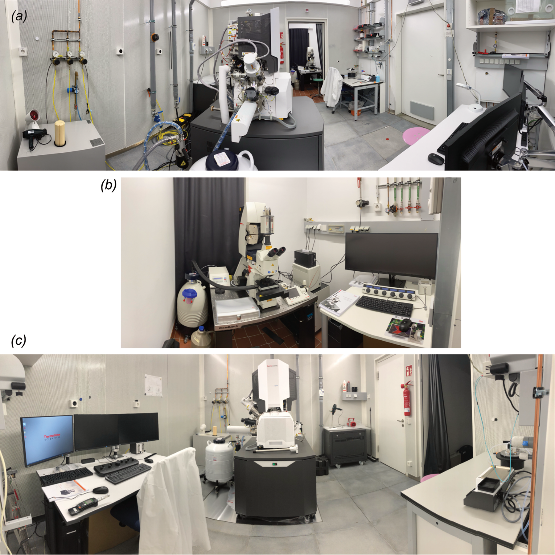
The techniques of FIB-SEM and cryo-FIB-SEM have become a major preparation requirement for tomography. The FIB-SEM allows a sample, whether it be cryo or at room temperature, to be thinned to a thickness suitable for viewing and data collection in the cryo-TEM at 300 kV. The FIB-SEM should be set up with a cold stage such that lamellae can be cut that are thin enough to be viewed for tomography in the cryo-TEM (150 nm or less). This is an important technique now for visualizing intracellular detail when it is not possible to isolate cellular components without damaging them (Marko et al., Reference Marko, Hsieh, Schalek, Frank and Mannella2007; Rigort et al., Reference Rigort, Villa, Bäuerlein, Engel and Plitzko2012; Schaffer et al., Reference Schaffer, Pfeffer, Mahamid, Kleindiek, Laugks, Albert, Engel, Rummel, Smith, Baumeister and Plitzko2019; Zachs et al., Reference Zachs, Schertel, Medeiros, Weiss, Hugener, Matos and Pilhofer2020). To identify areas of interest for FIB-SEM fluorescent probes can be incorporated in the sample and localised by fluorescence cryo-light microscopy and the samples then transferred to the FIB-SEM (CLEM) (Sartori et al., Reference Sartori, Gatz, Beck, Rigort, Baumeister and Plitzko2007) (Fig. 3).
Room for CLEM. (a) Aquilos cryo-FIB-SEM (TFS) with Leica SP8 confocal cryo-CLEM in the background. (b) Close-up of the cryo-CLEM. (c) Front view of the Aquilos FIB-SEM.
Equipment for cryo-specimen preparation
Even in the best cryo-EM facility, the main limiting factor for producing high-quality data is the sample. Every step of specimen preparation is essential, from assessing sample purity to preparing a suitable support for the sample (be it negative stain or vitrified) to plunge-freezing and storage of the vitrified samples. Ideally, a cryo-EM lab should have all of the following items:
(1) A carbon evaporator to produce clean carbon support films of a reproducible thickness on mica under high vacuum. High-quality carbon films are a requirement for preparing grids for negative staining.
(2) A glow discharge unit for making support films hydrophilic. This is essential not only for continuous carbon or holey carbon used for negative staining or cryo-EM, but also for more specialised supports like gold grids with gold holey films, or holey films back-coated with amorphous carbon or graphene.
(3) A light microscope for assessing the quality and integrity of carbon-coated grids or holey carbon film grids. The light microscope should be equipped for dark-field and phase contrast.
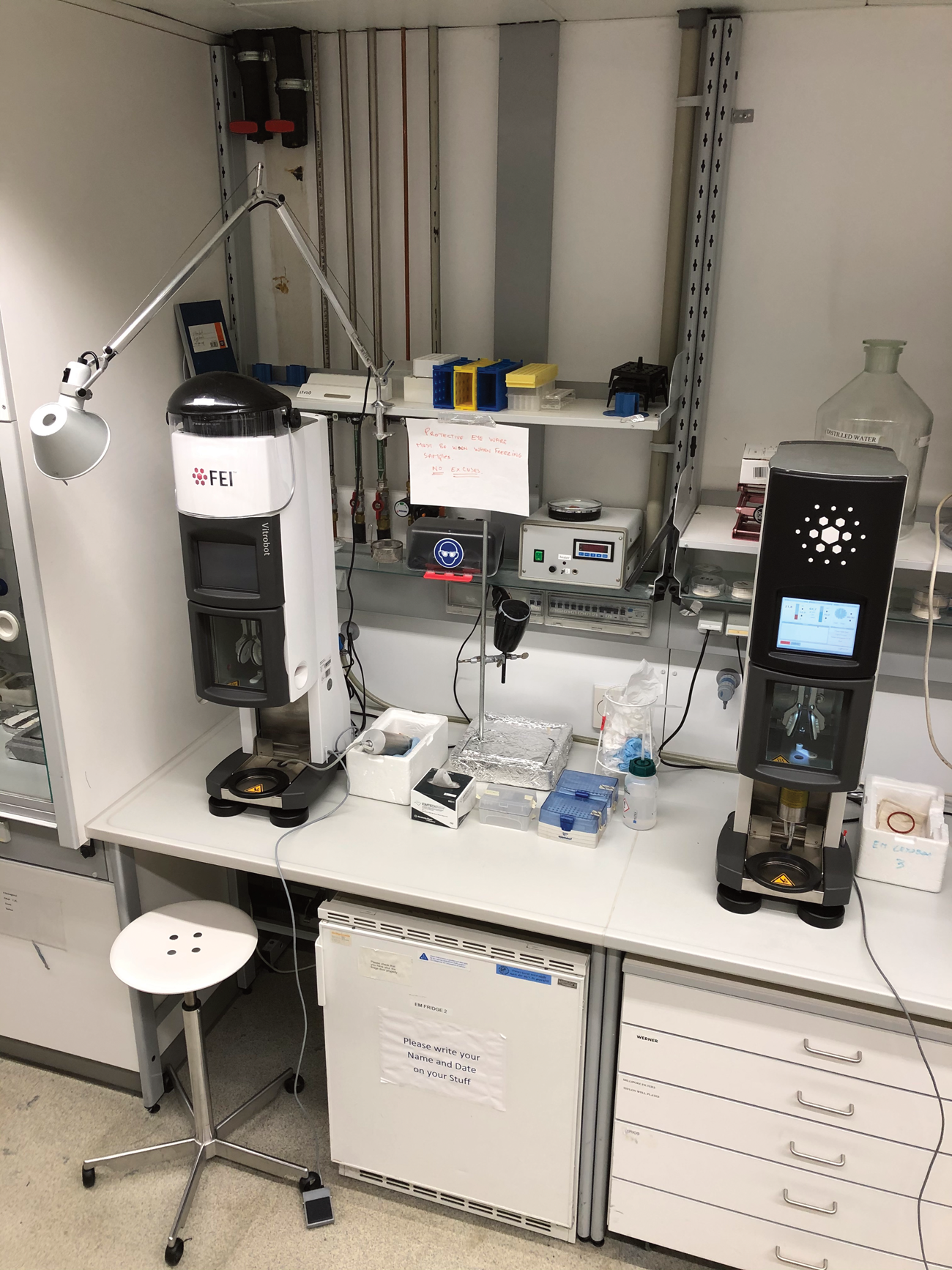
(4) A robotic plunge-freezer for the vitrification of samples. With this unit, grids can be frozen in liquid ethane, at such a fast rate that ice crystals cannot form. The unit also provides a humidity- and temperature-controlled environment to prevent drying of the samples prior to freezing. For safety reasons, the plunger needs to be set up such that the ethane can warm up and evaporate in a safe environment without the risk of explosion. This is most easily achieved by placing the plunger into a fume hood with a reduced airflow, or by placing it into a special, safety-controlled area. Commonly used plunge-freezers are the Vitrobot from TFS (Fig. 4), the Cryoplunge 3 from Gatan or the automatic plunge freezer EM GP2 from Leica. As an alternative to plunge-freezers, which require comparatively large amounts of sample, instruments are being developed that can deposit nanolitre volumes onto grids such that blotting is no longer required. Examples are the Chameleon (SPT Labtech) (based on the Spotiton technology (Dandey et al., Reference Dandey, Wei, Zhang, Tan, Acharya, Eng, Rice, Kahn, Potter and Carragher2018)); the VitroJet (Ravelli et al., Reference Ravelli, Nijpels, Henderikx, Weissenberger, Thewessem, Gijsbers, Beulen, López-Iglesias and Peters2019) (CryoSol); or the Shake-it-Off (Rubinstein et al., Reference Rubinstein, Guo, Ripstein, Haydaroglu, Au, Yip, Di Trani, Benlekbir and Kwok2019), which can be built by any mechanical workshop from open-source 3D-printed parts.
(5) A dedicated area for mounting cryo-grids onto the specimen cartridges for the high-end microscopes like the Krios, Glacios or Cryo ARM.
(6) For microscopes without a built-in cold stage, a cryo-specimen holder with a dedicated specimen loading station. This holder would usually be ordered together with the electron microscope. For stable performance, the Dewars and tips of these holders have to be regularly pumped. A dedicated pumping station is required for this purpose. They are commercially available or can be home-built.
(7) Liquid nitrogen Dewars for long-term storage of cryo-specimens. It is advantageous to prepare cryo-samples when a biological sample is fresh and then store the frozen grids until microscope time is available. Grids should be stored in special containers which keep the grids free of surface ice contamination (Fig. 5a). Grids can also be stored mounted in the cartridges for microscopes like the TFS or JEOL microscopes for repeated data collection sessions (Fig. 5b–d).
(8) A source of fresh triple-distilled water for making stains and buffers.
(9) Adequate supply of clean liquid nitrogen. A large amount of liquid nitrogen is used for cryo-EM for sample preparation and for cooling anticontaminators and storage containers. A 300 kV cryo-EM uses up to 200 l of liquid nitrogen per week. The ideal setup would have one or two 200 l self-pressurizing containers and one 10 l Dewar per microscope. Care should be taken to keep the contents of the containers ice-free. The Dewars should be emptied and dried regularly to prevent ice contamination of the samples.
Vitrification robots. Two different Vitrobot models from TFS.
Storage of cryo-grids. (a) Storage Dewars. Inset: Grid storage boxes. (b) Commercially available plastic, four-slot box for cryo-grids or Krios specimen cartridge (TFS). (c) Custom-designed eight-slot aluminium box for cryo-grids or Krios cartridges with identifying number. (d) Custom-designed two-slot aluminium box for Polara cartridge with identifying number. Scale bar: 2 cm.

Rooms for cryo-EM
The room for the main microscope
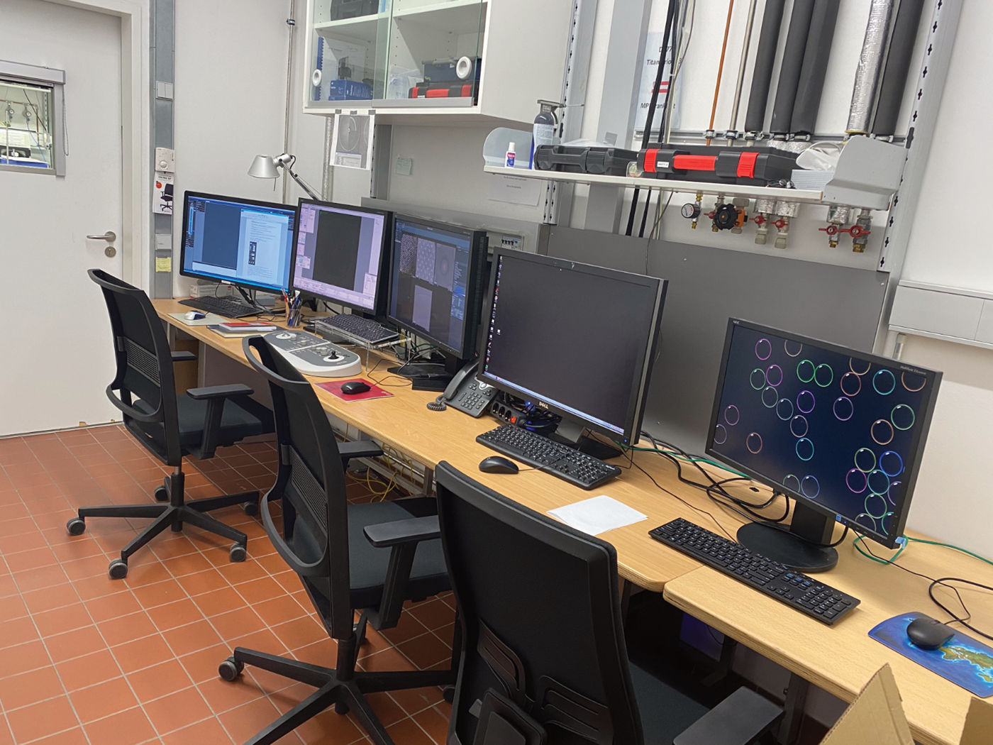
The room for the cryo-EM used for high-resolution data acquisition has very special requirements. Room dimensions and services will be dictated by the EM that is to be housed, and it is essential to consult the microscope supplier at an early stage regarding these requirements, as specifications will vary. Most 300 kV cryo-EMs will require a room with a floor area of at least 6 × 6 m2 and a height of 4 m. In addition to the microscope room, an adjacent room measuring at least 2 × 3 m2 will be required for ancillary equipment including water coolers (Fig. 6a), vacuum pumps, and data acquisition and storage computers (Fig. 6b). This room will need especially powerful air conditioning, as both the water coolers and computers generate a great deal of heat. Electron microscopes of the latest generation are remotely controlled and require a separate control room of at least 2 × 4 m2, either adjacent to the microscope room or at a maximum distance (usually 15 m) set by the length of cables for the microscope control panels and monitors (Fig. 7).
Ancillary equipment room. (a) Water coolers for two TFS cryo-TEMs (Van der Heijden Labortechnik GmbH). (b) Servers for a Falcon 3 camera (top) and for a K3 camera (below).

Control room for a Titan Krios.
The main microscope room will require stable temperature and low humidity. A constant temperature of around 22°C ± 0.5°C and humidity around 20% is good. Even lower humidity would be desirable as it helps reduce ice contamination of the specimens but is expensive to maintain in most locations. Services to the room should include three-phase and regular power supplies, a supply of clean, dry pressurised air at ~9 bar and a dry nitrogen gas supply at a maximum of 3 bar. Dry nitrogen is used for venting the microscope column or the specimen loading chambers or for pressurizing the large Dewars used for liquid nitrogen delivery to the cryo-TEM. The supply of water-free nitrogen gas is usually not inexhaustible, so it is best to limit the overall pressure on this line to 3 bar, which conserves liquid nitrogen use, and higher pressure is rarely, if ever, required. All high-end cryo-EMs will collect data with a direct electron detector camera, so fibre optics data transfer lines should be available with at least 10 Gb transfer speed.
Current high-end EM models come in a sound-proof enclosure with dynamic pneumatic suspension. Even so, the EM room should have a low ambient noise level and the floor should be vibration-free. Ideally, the microscope room should have a central heavy concrete plinth to provide a stable, vibration-free base for the microscope (Fig. 8a). A concrete plinth measuring 4 × 4 m2 and 1 m high would be ideal for most 300 kV electron microscopes. The surrounding floor should be decoupled from this base to prevent mechanical vibrations being transmitted to the microscope. Having a floating or false floor around the plinth (Fig. 8b) allows the running of electrical cables, water cooling pipes and vacuum lines to the microscope without causing obstructions around the EM, allowing easy access for maintenance and the supply of coolant gases.
Floor design for a cryo-EM room. (a) Concrete plinth for electron microscope, 4.0 × 4.0 × 0.8 m3. The plinth is T-shaped to enable installation of active vibration compensators if necessary. (b) False floor above the EM foundation, to decouple any floor vibrations, e.g. caused by footsteps, from the microscope and improve microscope stability. The underspace of this floor accommodates all the cables, vacuum and cooling pipes that connect to the microscope. In this way, the double floor helps to make service and maintenance work around the microscope more convenient and safer.

Ancillary power supplies and high-voltage tanks should be positioned around the EM at distances recommended by the microscope manufacturer. Ideally, microscope power supplies and the high-voltage tank need to be at a distance of at least 1.5 m from the EM column. Adequate space should be left at the front of the EM to provide easy access for specimen loading.
The temperature of the room should be stable and controlled to within ± 0.5 °C. Air delivery to the room is best through large wind socks (Fig. 9a), which distribute the air evenly around the room and prevent draughts that can cause the EM column to bend very slightly. The ventilation system itself should not generate noise. It is very useful if the humidity of the room can be controlled at a level of 10–20%. This reduces ice contamination during cryo-sample preparation and will help to maintain a low contamination rate in the microscope. For safety reasons, it is important to have adequate ventilation in the EM facility, not least in regards to the large volumes of liquid nitrogen that are routinely used for cryo-EM work. Oxygen sensors and alarms must be installed in all rooms where liquid nitrogen is used.
Measures to reduce vibrations in the EM facility. (a) Wind sock. (b) Acoustic panelling. (c) Soundproof cabinet for data servers.
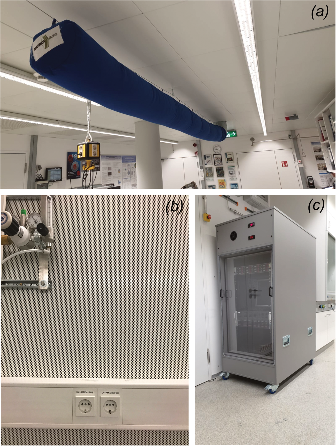
Noise, generated by the EM itself or by ancillary equipment, can affect high-resolution data dramatically. Room noise can be suppressed by acoustic panelling (Fig. 9b). Note that servers used for the automatic data collection on a direct electron detector can be extremely loud and should be housed in special sound-proof cabinets (Fig. 9c). In general, room noise should not exceed 40 dB.
Careful consideration should be given to the electrical wiring to the EM room. Large power cables should be run into the room at ground level, avoiding close proximity to the microscope column because of electromagnetic fields that can affect the EM performance. Good room illumination is necessary for service and repairs. Lighting circuits should be terminated at a power switch at the room entrance. For the maintenance of the EM column or the exchange of the field emission gun, an overhead gantry crane is very useful (Fig. 10).
Overhead crane for lifting heavy equipment. Crane with a 1000 kg capacity suitable for a 300 kV microscope. Such a crane is very useful for installation and servicing of high-end electron microscopes. However, most deliveries of large, high-end electron microscope now include a crane, sometimes even contained within the microscope housing.

The electron microscope room should be as free as possible from vibrations and electromagnetic fields, which both degrade image quality. It must be remembered that electron microscopes are highly sensitive detectors of electrical and magnetic fields, as well as of building vibrations and any room chosen or built for electron microscopes needs to be well shielded from these disturbances. Prior to purchase, the manufacturer would usually perform a site survey to check the suitability of the room. Making a room free from mechanical vibrations is technically not difficult as one can install the microscope on a solid concrete base that is decoupled from the surrounding structures (Fig. 8a). Moreover, most modern high-resolution electron microscopes have an elaborate suspension system that tunes out mechanical vibrations. Any acoustic noise can be suppressed by the microscope enclosure (Fig. 2b–d) or sound proofing, e.g. by acoustic wall panels (Fig. 9b). The more annoying problem of electromagnetic fields (higher than 80 nT peak-to-peak for a TEM) most often originates from outside the room, e.g. from a large instrument like a centrifuge, or, worse, a railway line. Any equipment that generates magnetic fields, even very confined local fields like those of a magnetic stirrer, should not be located closer than 15 m to the electron microscope. If stray electromagnetic fields are a problem, the microscope room can be shielded by active field compensators. Compensating coils should be part of the initial planning, but can be added later if necessary, at a moderate cost.
Rooms for screening microscopes
The requirements for the microscope used for negative staining, usually a 120 kV instrument, are less stringent. A room measuring 4 × 4 m2 with a 1.5 × 2 m2 adjoining room for a water cooler should be adequate, but it must, of course, fulfil the EM manufacturer's specifications. It should have a stable foundation, minimum noise and electrical fields, and stable room temperature.
To ensure high throughput and optimum use of the high-end cryo-TEMs it is advisable to have a dedicated EM for optimising cryo-samples. This microscope could be a 200 kV EM, which has less stringent room requirements than a 300 kV TEM. A room measuring 4 × 5 m2 and 3.5 m high would be sufficient.
Rooms for FIB-SEM
The room for a cryo-FIB-SEM (Fig. 3) needs to be at least 4 × 4 m2. The room height for these microscopes does not need to exceed 2.5 m, as the FIB-SEM has a much shorter column than a TEM. Plenty of space is required for access to the microscope from all sides for specimen loading and service. It should be noted that a cryo-FIB-SEM is usually set up with a cryo-light microscope nearby in an adjacent room or in the same room for CLEM work, so special attention should be given to these requirements. The light microscope should be relatively close to the FIB-SEM as samples need to be transferred quickly. A cryo-light microscope will quite easily be accommodated in a room of 2 m × 2 m. Room humidity is of paramount importance in a CLEM room, as contamination of samples is difficult to manage, so a relative humidity of 20% or less is advisable.
Specimen preparation room
The EM facility preparation lab needs to be set up in such a way that it allows immediate and easy access to all equipment required for preparing the samples, for viewing first in negative stain, then freezing and viewing in the cryo-EM. The lab should be not too crowded, with adequate space for wet bench work. It should include a dedicated area for preparing support films and negatively stained grids as well as safe areas for freezing samples and designated benches used for storing cryo-grids and loading frozen grids into the microscope cartridges.
The time needed for preparing cryo-samples always exceeds the amount of time available for screening or data collection in the microscopes, so provisions need to be made for the storage of large numbers of samples frozen on grids for future viewing and data collection.
This lab will need to accommodate automatic plunge-freezing units and equipment for generating carbon support films. In addition, specialist apparatus, such as glow-discharge units or plasma cleaners, will be required for altering the surface properties of these support films to enhance protein adhesion, or ensuring the protein stays in the vitreous ice holes.
It is advantageous to have the EM lab centrally located with respect to all the microscopes and to have the whole unit controlled by one central air-conditioning system. That way the temperature and humidity of the whole lab can be kept constant. This helps tremendously with consistent, reproducible high-quality sample preparations.
Specimen preparation, especially sample freezing in a thin film of vitrified buffer to achieve the perfect distribution of protein orientations in the optimum thickness of ice, is by far the most difficult step and can be a serious bottleneck. So, having a preparation lab in the EM facility (Fig. 1) is a major advantage.
Liquid nitrogen supply
The volume of liquid nitrogen that is used by a cryo-EM facility on a daily basis is substantial. As mentioned above, each high-end or screening instrument will require on average 200 l of liquid nitrogen a week supplied directly to the microscope from a self-pressurised Dewar positioned next to the EM. A cryo-EM lab also requires large volumes of water-free liquid nitrogen for the freezing and storing of samples. A good solution is to have an independent source of liquid nitrogen supplied directly to a filling room near the EM lab, e.g. a large 3000 l storage tank (Fig. 11a). The storage tank should be connected to a small room (Fig. 11b) for filling the self-pressurising Dewars (Fig. 11c) that go into the EM lab. This arrangement has the added advantage of supplying pure water-free nitrogen gas that is generated from the large storage tank. To ensure liquid nitrogen is always available, the tank is fitted with an alarm system that automatically sends a message to the supply company when the level gets low.
Liquid nitrogen supply. (a) Liquid nitrogen storage tank with 3000 l capacity. (b) Filling room for liquid nitrogen Dewars supplied by the 3000 l storage tank in the adjacent room. (c) Self-pressurising liquid nitrogen Dewar for automatic cooling of a Krios microscope.

EM storage rooms
It is quite common for an EM facility to be in a process of having new microscopes or other equipment installed and older equipment replaced or upgraded. Installing new microscopes is both time-consuming and complicated because the new microscope may be very different from the one it is replacing, and once the old EM is removed the room will need modifying before the new one is installed. Even installing a new detector, energy filter or field emission gun will be time-consuming and require sufficient space. These tasks are made easier if there is a separate room where the new EM can be temporarily stored and unpacked.
Secondly, all microscopes come with large numbers of spare parts and service tools, all of which need to be stored but be readily at hand when they are needed. Therefore, it is important to have a sufficiently large, well-organised storage space in the facility.
The ideal solution would be to have two rooms dedicated to this purpose. The first one can be a small room of 3.0 m × 4.0 m and 3.0 m high for delicate measuring equipment, such as leak detectors, sensitive electronic meters and vacuum gauges. This room should be fitted with storage cupboards and shelves. It can also be used for all the spare parts and small service tools that come with a new microscope.
The second room should be considerably larger, if possible 6.0 m × 6.0 m with a 4.0 m ceiling. Such a room would be ideal for temporary storage and unpacking or packing of new or outdated instruments. It is also useful for equipment that is not used frequently, such as spare vacuum pumps, water coolers, step ladders and ladders, and a large hydraulic fork lift for moving heavy equipment, as well as temporary storage of packing material. The ceiling height must be sufficient to accommodate a 300 kV microscope, which comes in large boxes. The rooms should have easy access to a loading ramp through double doors for microscope delivery. Very useful is a ceiling crane that can lift weights up to 1000 kg to facilitate the handling of heavy pieces of equipment.
Services for these storage rooms should include 3-phase and single-phase power supplies up to 32 A, along with standard power sockets. This would allow the powering-up of equipment if required for service or maintenance, e.g. vacuum for a field emission gun until it can be installed on the microscope. It would make sense for these rooms to have adequate ventilation and temperature control, as much of the equipment stored there will be sensitive to temperature or excessive humidity. It would be useful to have both pressurized nitrogen and air supplies, and a large sink with hot and cold water for repairing and servicing equipment, e.g. the microscope water coolers, which will be necessary from time to time and can be messy. Some of the equipment in the storage room, e.g. a replacement field emission gun, a high voltage tank, or a complete camera and energy filter unit would need to be connected to a standby power supply to maintain a vacuum.
EM facilities have to be dynamic and adapt to changing needs in regards to microscopes and ancillary equipment. Exchange of equipment should have a minimum impact on the running of the facility that needs to operate 24 h a day, 7 days per week. The importance of good storage space should therefore not be underestimated.
Operation, maintenance and budgeting
Safety in the cryo-EM lab
The cryo-EM facility uses large volumes of liquid nitrogen, not only for cooling the microscopes but also for freezing samples and sample storage. Therefore, there is always a lot of liquid nitrogen in the facility. The low temperature can cause burns. To avoid accidents users should always wear safety goggles and gloves when handling liquid nitrogen. One litre of liquid nitrogen will evaporate into about 700 l of asphyxiating nitrogen gas that replaces oxygen in the room atmosphere. Liquid nitrogen must therefore be used carefully and should only be transported in specifically designated vessels. To avoid oxygen shortage, all rooms in the EM facility must have very good ventilation and should have oxygen sensors that will activate an alarm if the oxygen level drops below 19.5% in case of a liquid nitrogen spillage. Rooms where large amounts of liquid nitrogen are used, e.g. the liquid-nitrogen filling room, should have extra warning systems as a backup in case the primary warning system fails. Ideally, the outlet valve of the main liquid nitrogen storage tank should close automatically if a low oxygen level is detected and should not open again before the oxygen level has returned to normal.
A particular safety issue concerns liquid ethane, used for preparing cryo-samples in the freezing stations. Ethane gas is explosive and appropriate care should be taken whenever it is used. Ethane should always be liquified in a fume hood and any waste liquid ethane disposed of in the fume hood once the freezing has been completed. Liquid ethane causes worse burns than liquid nitrogen and during freezing of samples, safety goggles or a visor should be worn every time.
Another safety aspect to note is that all microscopes operating at an acceleration voltage of 200 kV or higher use sulphur hexafluoride (SF6) gas for electrical insulation in both the high-tension tanks and the field emission gun. The gas is heavier than air and asphyxiating. SF6 gas is also one of the most harmful greenhouse gases for our planet's atmosphere, so it should be recovered and not allowed to escape into the air. Also, SF6 at high temperatures can become very damaging to the human lungs if inhaled. Smoking or open fires are strictly forbidden when working with SF6. Therefore, these EM rooms should be equipped with SF6 sensors, along with extra ventilation outlets for emergency use. SF6 is expensive and normally collected for recycling during service or repair work.
Lastly, various toxic chemicals are routinely used in the EM lab, e.g. uranyl acetate and uranyl formate, which are also mildly radioactive and must not be ingested and generally handled with great care. Any waste must be disposed of in special containers for professional disposal. Otherwise, an EM lab is like any other wet lab and special attention should be given to careful use of acids and other dangerous chemicals. If the lab is designated biosafety level S1 or higher, the appropriate safety precautions should be employed in accordance with the regulations.
Staff of the cryo-EM facility
Any cryo-EM facility, if it is going to run smoothly, will require dedicated, highly qualified and experienced staff to ensure that everything operates correctly and to the highest standard.
The facility should be overseen by a manager whose responsibilities will entail the day-to-day managing of the facility, ensuring all microscopes are operating perfectly and any service or repairs can be organized rapidly to minimise downtime. The facility manager will oversee the running costs and most importantly make sure that the work being carried out is done to the highest standard. Large facilities will require support staff that can help oversee the daily operation of the microscopes and ancillary equipment. Instructing and teaching new users the techniques of cryo-EM will be a very important function of the staff.
The EM staff will have to control the optimum operation of the microscopes and preparation of any samples that will be observed, whether that be cryo or room temperature, so the EM manager must ensure that the staff are well versed in all EM techniques and new procedures that are presented as the facility keeps up to date with new developments in the field.
Finally, the facility manager will be required to control the budget with respect to running costs and the negotiation of service contracts as well as repairs to equipment that is not covered by service contracts.
EM alignment
A very accurate electron-optical alignment of the EM is essential for obtaining high-resolution images. The alignment of the 300 kV instrument for high-resolution data collection should therefore be checked carefully at least once every few days, with special attention to illumination alignment to correct for any beam tilt, coma or astigmatism which would limit data quality (Glaeser et al., Reference Glaeser, Typke, Tiemeijer, Pulokas and Cheng2011; Cheng et al., Reference Cheng, Eng, Alink, Rice, Jordan, Kim, Potter and Carragher2018; Glaeser, Reference Glaeser2019).
Automatic data collection, data storage and image processing
The prime function of a cryo-EM lab is to produce high-quality image data of biological samples as quickly and efficiently as possible, and the automatic data recording programmes can generate terabytes of data. Consequently, all microscopes recording such data volumes should be linked to an appropriate data storage system. For example, four high-end electron microscopes equipped with electron-counting cameras would need a storage system with at least a petabyte (PB) capacity. Larger and faster electron counting cameras are now coming onto the market, but at the same time, data formats are being developed such as electron event recording (Guo et al., Reference Guo, Franken, Deng, Benlekbir, Lezcano, Janssen, Yu, Ripstein, Tan and Rubinstein2020) that allow highly efficient storage of image information. Nevertheless, we can expect further significant growth in the requirements for data storage of cryo-EM data.
In order to ensure that recorded data are of the highest quality, online data processing should be carried out to check for electron-optical alignment and high resolution. This way users can ensure that data quality is always optimal. For example, the program WARP (Tegunov and Cramer, Reference Tegunov and Cramer2019) is able to align movie stacks on the fly and calculate the CTF of each image being recorded. Then the images that have good enough quality in respect to CTF cutoff are, in the case of single-particle data collection, selected to have the particles automatically picked and 2D class averages of the particles calculated, so one can rapidly determine if the sample quality is good enough for a high-resolution 3D map. The same is possible with, e.g. CryoSPARC Live (Punjani et al., Reference Punjani, Rubinstein, Fleet and Brubaker2017).
Cryo-EM data processing requires a powerful computer cluster such that single-particle or tomography data can be processed quickly and reliably using programs like RELION (Scheres, Reference Scheres2012; Kimanius et al., Reference Kimanius, Forsberg, Scheres and Lindahl2016; Zivanov et al., Reference Zivanov, Nakane, Forsberg, Kimanius, Hagen, Lindahl and Scheres2018) or CryoSPARC (Punjani et al., Reference Punjani, Rubinstein, Fleet and Brubaker2017). The processing of recorded data is often done by the customers of a shared cryo-EM facility. However, if the facility wants to perform image processing and structure determination locally, a computer cluster with at least 10 nodes of 4–6 high-end GPUs and 256 GB RAM would be required.
Maintenance
It is essential to perform routine maintenance on both the electron microscope and ancillary equipment regularly to ensure their optimal performance.
It is good practice to check the performance of the high-end EMs with a test specimen before every high-resolution data collection run. For resolution checks, a combined test specimen (holey carbon film with gold islands and graphitised carbon) can be purchased from various suppliers. For single-data collection a stable standard cryo-sample (e.g. apoferritin) is very useful for checking EM performance and data quality. However, a full image-processing cycle will be required every time.
Vacuum problems will result in ice contamination of the specimen. Regular data quality checks with a biological cryo-sample will reveal such problems so that the operator or a new sample cannot be automatically blamed for poor data quality.
The cooling of the electron microscope, especially of the lenses and the power supplies, is of great importance. It is therefore essential to check for stable temperature and flow rate of the cooling water every day, as any variation can have adverse effects on data quality.
High-end cryo-TEMs require occasional repairs and routine maintenance by qualified service engineers. On purchase of these instruments, a service contract should be negotiated to avoid long downtimes when problems occur. These contracts should include routine maintenance and spare parts (e.g. the exchange of a field emission gun on average once every 2 years) and may cover the electron detectors bought as part of the microscope purchase.
The maintenance of ancillary equipment is equally important. Equipment like high-vacuum coating units, glow-discharge units, plasma cleaners and plunge-freezers may also require routine quality tests or regular service and maintenance by the supplier, although service contracts are not normally required.
Budgeting and planning
The budget needed for setting up a cryo-EM lab is considerable, as are the subsequent running costs. The expense of setting up a room for any electron microscope is substantial and generally, the cost of a room for a 300 kV cryo-EM will be considerably more than for a 120 kV EM. As a rule of thumb, a good room for a 300 kV instrument will cost about 20% of the purchase price of the microscope. Note that the refurbishment of existing rooms can be as expensive as building a new room from scratch. It is important to remember that electron microscopes require rooms that will not limit their performance. Different makes of microscopes may have different requirements for room size and specifications, so when refurbishing a room or building a new one, careful consultation with the EM manufacturer at the earliest stage is important.
All companies that supply high-end cryo-EM equipment offer service contracts for their instruments. Service contracts are expensive but can be essential unless the laboratory employs a qualified and experienced cryo-EM engineer. They also ensure access to replacement components, which can otherwise cause unbudgeted high costs for spare parts and labour. A service contract minimises downtime because it ensures priority for service calls or repairs. It is advisable to negotiate a service contract when purchasing a new instrument and to ensure that the contract covers associated equipment, especially water coolers, electron detectors and energy filters when feasible. Note that cameras do not go wrong nearly as often as electron microscopes with their sophisticated electron optics, electronics and precision-engineered mechanics, so some labs might prefer to replace the camera parts and pay for service on a case-by-case basis rather than buying an expensive service contract. However, repairs to electron-counting cameras can be costly and time-consuming, especially when these cameras are combined with an energy filter. Having a service contract warrants having the system working again in minimum time and ensures the smooth operation of an EM facility.
Last but not least, large computer clusters are needed for image processing. Even when external users are responsible for their own data processing, the cryo-EM facility will need powerful computers for on-the-fly motion correction and possibly for a complete processing pipeline. Furthermore, extensive storage capacity is needed to keep, even temporarily, the large amount of data that are collected.
The future of the cryo-EM lab
Technical advances in electron cryo-microscopy are continuing at a tremendous rate, even though electron microscopes of the latest generation are superb. The combination of stable and bright electron sources, very stable electron optics, wonderfully stable cryo stages, ultra-clean vacuum and fast, sensitive direct electron counting cameras make present-day cryo-data collection relatively painless. There are areas where improvements in the technology of the microscope and detector designs will make data collection even better and faster in future. New cryo-specimen stages are being developed which allow very fast eucentric tilting for tomography data collection, so tomograms can be recorded in seconds rather than minutes. Direct electron detectors with substantially larger sensors will allow even more rapid readout, enabling the collection of much larger datasets with fewer images in a fraction of the time that is needed at present.
One of the major bottlenecks in cryo-EM is the optimisation of specimen preparation. This again will improve over the next few years with more advanced cryo-grid freezing machines that are already being produced and should ensure perfect cryo-grids of the optimum ice thickness and perfect particle distribution every time.
The field of cryo-EM has advanced so rapidly over the last few years that it is now the technique of choice for structural studies of protein complexes. Such is its success that it is becoming more popular than X-ray crystallography, particularly for membrane proteins and flexible protein complexes. A major drawback of the technique is the high cost of setting up a cryo-EM lab and to buy, install and maintain a high-end 300 kV cryo-TEM. One solution to this which is already being carried out is to set up EM user facilities that can provide access for many labs wanting to use this technique; however, preparing and checking the samples to see if they are suitable for data collection is still limiting, as one needs to have access to a cryo-EM to do this. One solution would be to establish less expensive 100 or 120 kV microscopes which can be made into low-cost cryo-screening microscopes. These microscopes can be set up at much-reduced cost in a larger number of labs and used to assess samples to medium resolution (4–8 Å) to see if the samples are suitable for taking to a high-end cryo-EM for a large high-resolution dataset.
It has recently been shown that a 100 kV cryo-EM with a side-entry cold stage fitted with a field emission gun electron source and a fast readout direct detector can deliver data of protein samples at a reasonably high resolution (Naydenova et al., Reference Naydenova, McMullan, Peet, Lee, Edwards, Chen, Leahy, Scotcher, Henderson and Russo2019). The fact that these microscopes run at a lower acceleration voltage means that even small proteins of ~100 kDa can be seen with minimal defocus because the lower kV ensures high contrast due to the higher electron scattering cross-section. In addition, the ratio of elastically to inelastically scattered electrons is more favourable for structural analysis at 100 kV than at 300 kV (Peet et al., Reference Peet, Henderson and Russo2019). One limit of these lower-voltage microscopes is that the spherical aberration constant of the objective lens must be kept below 2.0 mm and the chromatic aberration as low as possible if a resolution of ~3.0 Å or better is to be achieved. This means a narrow objective pole piece gap and consequently, stage tilting would be limited to about ± 10°, which normally would rule out electron tomography.
The problem of specimen preparation for good cryo-grids will be a bottleneck until one can solve the problem of preferred orientation of the proteins in the ice, uneven sample distribution and lastly the degradation of the sample by surface forces at the air–water interface prior to vitrification. These problems may be overcome by the development of new freezing devices that allow the application and freezing of samples in a controlled way, such that the air–water interface causes no damage to the protein.
In the not-too-distant future, every cryo-EM dataset that is recorded of an optimised sample will produce density maps to a resolution of 2.5 Å or better and then the structure can be modelled automatically. This may seem like a dream at present, but a few years back not many in the field would have expected single-particle cryo-EM to produce data that would seriously compete with, or surpass X-ray crystallography. Continuous improvements in both hardware and software for cryo-EM have pushed the resolution limit higher and higher in the years since 2013. The 3 Å barrier was broken in 2015 (Campbell et al., Reference Campbell, Veesler, Cheng, Potter and Carragher2015) and 2 Å already in the next year (Merk et al., Reference Merk, Bartesaghi, Banerjee, Falconieri, Rao, Davis, Pragani, Boxer, Earl, Milne and Subramaniam2016). A highlight in 2019 was a map of apoferritin at 1.54 Å (Hamaguchi et al., Reference Hamaguchi, Maki-Yonekura, Naitow, Matsuura, Ishikawa and Yonekura2019; Kato et al., Reference Kato, Makino, Nakane, Terahara, Kaneko, Shimizu, Motoki, Ishikawa, Yonekura and Namba2019) and in 2020 the breakthrough to true atomic resolution with two independent maps of apoferritin at 1.25 Å and 1.22 Å resolution (Nakane et al., Reference Nakane, Kotecha, Sente, McMullan, Masiulis, Brown, Grigoras, Malinauskaite, Malinauskas, Miehling, Yu, Karia, Pechnikova, de Jong, Keizer, Bischoff, McCormack, Tiemeijer, Hardwick, Chirgadze, Murshudov, Aricescu and Scheres2020; Yip et al., Reference Yip, Fischer, Paknia, Chari and Stark2020). All three structures were facilitated by different methodological advances. The 1.54 Å dataset was collected on a JEOL Cryo ARM 300 microscope equipped with a cold field emission gun electron source and an in-column energy filter (Hamaguchi et al., Reference Hamaguchi, Maki-Yonekura, Naitow, Matsuura, Ishikawa and Yonekura2019). The 1.25 Å dataset was obtained with a prototype instrument equipped with special electron-optical elements to increase its performance: a monochromator and a second-generation spherical aberration corrector from CEOS (Müller et al., Reference Müller, Massman, Uhlemann, Hartel, Zach and Haider2011) built into a TFS Titan Krios equipped with a Falcon 3 detector (Yip et al., Reference Yip, Fischer, Paknia, Chari and Stark2020). Finally, the 1.22 Å apoferritin structure was produced with a Titan Krios with a new cold field emission electron gun optimised for low energy spread plus a fast Falcon 4 camera with high DQE in combination with an optimized electron energy filter (Nakane et al., Reference Nakane, Kotecha, Sente, McMullan, Masiulis, Brown, Grigoras, Malinauskaite, Malinauskas, Miehling, Yu, Karia, Pechnikova, de Jong, Keizer, Bischoff, McCormack, Tiemeijer, Hardwick, Chirgadze, Murshudov, Aricescu and Scheres2020). The data for the 1.22 Å map was collected in 36 h. What all these developments have in common is less energy spread in the electron source, contributing to a higher signal-to-noise ratio in the images at high spatial frequency. Post-specimen optical aberrations were compensated by either electron-optical correctors (Yip et al., Reference Yip, Fischer, Paknia, Chari and Stark2020) or computer algorithms (Hamaguchi et al., Reference Hamaguchi, Maki-Yonekura, Naitow, Matsuura, Ishikawa and Yonekura2019; Nakane et al., Reference Nakane, Kotecha, Sente, McMullan, Masiulis, Brown, Grigoras, Malinauskaite, Malinauskas, Miehling, Yu, Karia, Pechnikova, de Jong, Keizer, Bischoff, McCormack, Tiemeijer, Hardwick, Chirgadze, Murshudov, Aricescu and Scheres2020).
Obviously, the next frontier would be to achieve a resolution beyond 1 Å with radiation-sensitive biological specimens. The present developments suggest that this may be possible, but the electron optics will have to improve and a tremendous amount of data will have to be collected. When recording EM data at such extremely high resolution many new factors come into play, especially the electron-optical alignment of the electron source and imaging lenses needs to be perfect. This means more elaborate and hence expensive electron gun sources and lens correctors, not to mention larger and faster detectors so data can be recorded at a higher rate. The improvement in speed of processing clusters is also an important factor. Ultimately top-end electron microscopes will become much more complex and expensive, and perhaps just a few selected labs will have such microscopes that can be used by a sharing scheme over a national or international level. However, the programmes used for data processing are helping tremendously to push the resolution of the data ever higher (Zivanov et al., Reference Zivanov, Nakane, Forsberg, Kimanius, Hagen, Lindahl and Scheres2018), and the ability to classify large heterogeneous datasets and sort out many different conformation classes makes it possible to see biology in action.
The sample will always be limiting, but I am sure these problems will all be solved as the biochemistry and cryo-specimen preparation is improved. The resolution revolution continues.
Acknowledgements
I thank Werner Kühlbrandt and Janet Vonck for many discussions and for their comments on the manuscript. I thank Richard Henderson and Özkan Yildiz for discussions. I thank Friederike Joos, Simone Prinz, Susann Kaltwasser, Mark Linder and Sonja Welsch for their contributions to the smooth running of our EM lab.
Conflict of interest
None.


 Open access