

1. INTRODUCTION
The integrated navigation system of an Inertial Navigation System (INS) and the Global Positioning System (GPS) has been extensively used in Unmanned Aerial Vehicles (UAVs). The consistent stability of GPS can be used to prevent long-term drift of INS. On the other hand, the INS has excellent high-frequency properties, which naturally compensate for the low refresh rate of GPS. The INS solution and GPS data can be fused by an Extended Kalman Filter (EKF). However, GPS is a line-of-sight system that can be blocked in a challenging environment. When GPS signal outages occur, the EKF works in prediction mode, and the navigation accuracy decreases gradually due to the inaccurate system error model. To improve the prediction mode of EKF, many bridging methods have been proposed.
Considering the strong nonlinear relationship between the INS solution and its errors, which can be approached by multi-layer perceptron Neural Networks (NN), Artificial Intelligence (AI) has been applied extensively to bridge GPS outages. Using INS data as input and the difference between GPS and INS as output, the feed-forward NN can be trained offline and INS errors can be provided and compensated during GPS outages (Chiang et al., Reference Chiang, Noureldin and El-Sheimy2003). Subsequently, the introduction of the wavelet multi-resolution analysis into NN improved its performance (Noureldin et al., Reference Noureldin, Osman and El-Sheimy2004). Hopfield NN is used to estimate INS errors (Shi et al., Reference Shi, Zhu and Sun2005), and Radial Basis Function (RBF) NN is applied later to improve the INS-only solution (Semeniuk and Noureldin, Reference Semeniuk and Noureldin2006). Related works were subsequently researched (Chiang et al., Reference Chiang, Noureldin and El-Sheimy2006; Chiang et al., Reference Chiang, Noureldin and El-Sheimy2008; Pang and Liu, Reference Pang and Liu2009; Lee et al., Reference Lee, Grejner-Brzezinska and Toth2012).
However, all these recurrent NN require very large memory capacity and much processing time for retrieving the stored learning parameters. To improve the real-time performance, an auxiliary model based on the Adaptive Neuro-Fuzzy Inference System (ANFIS) was applied, with an improvement in the positioning accuracy (Abd Elhamid et al., Reference AbdElhamid, Noureldin and El-Sheimy2007). Further related works have been carried out for optimisation (Hasan et al., Reference Hasan, Samsudin and Ramli2011). Nevertheless, the immature AI algorithm is still at an early stage of development, so that difficulties of online training and optimisation of parameters limit its implementation in real time control systems.
Considering that the behaviour of dynamic systems is usually frequency dependent in a specific frequency band, a frequency-domain method was proposed (El-Diasty and Pagiatakis, Reference ElDiasty and Pagiatakis2010). The Least Squares Frequency Transform (LSFT) was used to transform data series from time domain to frequency domain, and then inverse LSFT were used to transform inversely to obtain the impulse response. Their experiment results showed that the frequency-dependent INS/GPS response model is superior to the NN model for 2D velocities and positions during GPS outages. However, the impulse response model needed to be accurately developed using GPS information, and the convergence property was not strictly proved.
Contrasting with algorithm innovation ideas, approaches utilising sensor redundancy and reconfiguration have been proposed in recent years. Lasers, infrared sensors, and radio equipment are introduced in navigation systems during GPS outages (Achtelik et al., Reference Achtelik, Bachrach, He, Prentice and Roy2009; Soloveieva and Rutkowski, Reference Solovieva and Rutkowski2009; Kukshya et al., Reference Kukshya, Krishnan and Kellum2005), which detect the range and bearing relative to specified points. These kinds of integration schemes increase the complexity of navigation systems, and some of them also rely on external signals. For fixed-wing UAVs with common navigation systems, it is necessary to apply more practical and effective methods to bridge GPS outages.
In this paper, we propose a new navigation algorithm for bridging GPS outages based on the common INS/GPS integrated navigation system that is equipped with barometer and air speedometer. The approximate wind model is developed, including the constant component plus additional wind turbulences. Wind states can be estimated so long as the GPS satellite signal remains unobstructed. During GPS outages, we update the angle of attack using its dynamic model, and then use the result to generate the airspeed vector. Corrected by the wind speed estimate, the ground speed is obtained. To compensate the accelerometer measurement, a centripetal force model is built, motion acceleration is derived, and then the gravity vector is estimated. This inertial direction is then used as the attitude observer. The compensated ground speed and gravity vector together with barometric height measurements provide velocity, attitude and altitude observations during GPS outages, which enable the reconstruction of a new integrated navigation system. Finally an EKF is applied to estimate the INS errors. The main contribution of this paper is that we develop a new navigation algorithm for bridging GPS outages based on the reconstruction of the low-cost integrated navigation system that is conventionally used for fixed-wing UAVs.
Following this introduction, we develop the wind model to estimate the wind velocity in Section 2. Section 3 describes observers for attitude, heading, velocity, and altitude during GPS outages. The navigation system is reconstructed and INS errors are estimated in Section 4. Finally, the real-time hardware-in-loop simulations for our fixed-wing UAV are implemented, and with comparison to INS/GPS integrated navigation system, assessment of the algorithm is given in Section 5. Conclusions are provided in Section 6.
2. THE WIND MODEL
During GPS outages, no velocity and position observations are provided. Common fixed-wing UAVs are usually equipped with a barometer and air speedometer. The airspeed that is obtained from the air speedometer can be considered as the approximation of ground speed in gentle wind, and cause negligible navigation errors. However, in strong wind, errors due to this approximation are too large to be ignored. To limit velocity errors, airspeed should be transformed into ground speed. Thus, wind speed should be estimated and compensated.
The typical wind consists of constant wind, gust and turbulent flow. In a certain period of time, the constant wind within a certain area can be considered invariant. Gust, which is time-variant and is affected by its previous status, is approximately regarded as an auto-correlated process. Considering its randomness, the turbulent flow is thus modelled as noise in the sensor measurement. Thus, we divide the wind velocity into three parts in the navigation frame (n): the constant part vnc, a simplified one-order interrelated stochastic process vnr, and the wind turbulence is considered as white noise Δg. We assume that vnr varies one-order interrelated with its current state and a time constant T a. Then, the dynamic characteristic is described as:
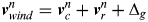 $${\bi v}^n _{wind} = {\rm} {\bi v}^n _c + {\bi v}^n _r + {\rm \Delta} _g $$
 $${\bi \dot v}^n _c = 0$$
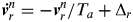 $${\bi \dot v}^n _r = - {\bi v}_r^n /T_a + {\rm \Delta} _r $$
Where Δr is the white noise that drives the one-order interrelated stochastic process.
Six-dimensional states are required to build the wind speed propagation equations, including three for vnc and three for vnr:
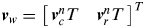 $${\bi v}_w = {\rm} \left[ {\matrix{ {{\bi v}^n _c ^T} & {{\bi v}^n _r ^T} \cr}} \right]^T $$
Considering Equations (2)–(4), the approximate dynamic model of wind velocity v w is deduced:
 $${\bi \dot v}_w = \left[ {\matrix{ {{\bi 0}_{3 \times 3}} & {{\bi 0}_{3 \times 3}} \cr {{\bi 0}_{3 \times 3}} & {diag\left[ { - \displaystyle{1 \over {T_a}}, - \displaystyle{1 \over {T_a}}, - \displaystyle{1 \over {T_a}}} \right]} \cr}} \right]{\bi v}_w + \left[ {\matrix{ {{\bi 0}_{3 \times 3}} \cr {{\bi I}_{3 \times 3}} \cr}} \right]{\rm \Delta} _{r[3 \times 1]} $$
When the on board GPS receiver works normally, position and velocity can be obtained. The EKF can effectively fuse INS solutions and GPS data, and then high quality estimations for attitude, velocity, and position are provided (Fu et al., Reference Fu, Deng and Zhang2003). Thus, the wind speed is expressed by the equation:
 $${\bi \hat v}_{wind}^n = {\bi \hat v}^n - {\bi C}_b^n {\bi \hat v}^b _{airspeed} $$
where  ${\bi \hat v}^n $ is the ground velocity of the UAV that is expressed in the navigation frame, ${\bi \hat v}^b _{airspeed} $ is the airspeed of the UAV expressed in the body-fixed frame, and Cbn is the direction cosine matrix from the body-fixed frame to the navigation-frame.
The observation model can be deduced from Equations (1) and (4)
 $${\bi \hat v}_{wind}^n = \left[ {\matrix{ {{\bi I}_{3 \times 3}} & {{\bi I}_{3 \times 3}} \cr}} \right]{\bi v}_w + {\bi I}_{3 \times 3} {\rm \Delta} _{g[3 \times 1]} $$
If only GPS data is available, the system model for wind velocity is established, as shown in Equations (5) and (7). Then, the constant wind and its covariance can be estimated through an EKF. Moreover, the barometric height is calibrated by the GPS altitude solution. Once GPS outages occur, if the constant component of wind speed does not vary to a large degree, the wind estimation can be used to compensate the raw measurement of the air speedometer, and the calibrated barometric height is a substitute for GPS altitude. All of the compensated observations will be applied to reconstruct the measurement equation in Section 4. Even if the assumption about the constant wind is challenged, or the turbulence temporarily deteriorates to some extent, which actually frequently occurs, the closed-loop navigation is not as greatly influenced as the wind speed estimation itself. There are two reasons. First, although the instantaneous wind speed changes frequently, its covariance rarely changes rapidly so there are no marked deviations from the well-estimated value. Second, depending on the state and noise covariance matrices, the filter itself has natural low-pass properties, and near-optimal estimations are obtained. Thus, the naturally low-pass EKF is somewhat robust to resist disturbances even though wind velocity is not ideally maintained.
3. OBSERVATION OF ATTITUDE, HEADING, AND VELOCITY
In this section, a new method to observe attitude, heading, and velocity during GPS outages is presented. Airspeed is corrected by the estimation of angle of attack, compensated by the wind speed, and then used to derive the motion acceleration. Thus, gravitational direction is extracted, and attitude is observed after the motion acceleration is subtracted from the raw measurement of the accelerometer. Heading is then derived from magnetic field strength that is measured by the Inertial Measurement Unit (IMU). Once Eulerian angles are obtained, the corrected ground speed can be transformed into the navigational frame and provide the velocity observer.
3.1. Attitude observer
The gravity vector is decomposed into the body-fixed frame according to the attitude of the carrier
 $${\bi g}^b = \left[ {\matrix{ {g_x^b} \cr {g_y^b} \cr {g_z^b} \cr}} \right] = {\bi C}_n^b {\bi g}^n = \left[ {\matrix{ { - g\sin \theta} \cr {g\cos \theta \sin \phi} \cr {g\cos \theta \cos \phi} \cr}} \right]$$
where x, y and z represent the three axes of the body-fixed frame, which point forward, rightward and downward respectively. Cnb is the direction cosine matrix from the navigation-frame to the body-fixed frame, ϕ and θ are roll and pitch angles, gb and gn are gravity vectors expressed in body-fixed frame and navigation frame respectively, and g is the magnitude of gravity vector. Considering the formulas above, roll and pitch is obtained:
 $$\hat \phi _g = \left\{ {\matrix{ {\pi + \tan ^{ - 1} (g_y^b /g_z^b ),} & {(g_y^b \gt 0,g_z^b \lt 0)} \cr {\pi /2,} & {(g_y^b \gt 0,g_z^b = 0)} \cr {\tan ^{ - 1} (g_y^b /g_z^b ),} & {(g_z^b \gt 0)} \cr { - \pi /2,} & {(g_y^b \lt 0,g_z^b = 0)} \cr { - \pi + \tan ^{ - 1} (g_y^b /g_z^b ),} & {(g_y^b \lt 0,g_z^b \lt 0)} \cr}} \right.$$
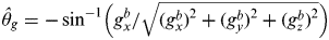 $$\hat \theta _g = - \sin ^{ - 1} \left( {g_x^b /\sqrt {(g_x^b )^2 + (g_y^b )^2 + (g_z^b )^2}} \right)$$
Typical accelerometers measure the sum of the motion acceleration ab and the gravity acceleration gb, which are both expressed in the body-fixed frame b. Normally, these two hybrid components are completely mixed, and it is impossible to separate one part from another directly. Thus, the motion acceleration has to be obtained using other special methods, and then compensated from the raw output of accelerometers (fb). Gravity acceleration then can be extracted by:
 $${\bi g}^b = {\bi a}^b - {\bi f}^b $$
Once the gravity vector is obtained, attitude can be calculated according to Equations (9) and (10). As the extracted gravity acceleration has no long-term drift, the calculated attitude has excellent low-frequency characteristics. However, the output of the accelerometer is always highly corrupted by carrier vibration, which reduces the measurement accuracy and makes the high-frequency component useless. In contrast, angular data from the gyro has good high-frequency characteristics and is compensative to the accelerometer. Thus, attitude calculated from the gravity vector is regarded as the attitude observation, which is highly valuable for navigation reconstruction.
3.2. Motion acceleration
For a steady, straight flying fixed-wing UAV, motion acceleration can be ignored. However, in manoeuvring flights, the motion acceleration has to be compensated so as to ensure the estimation accuracy of the gravity vector. To build the dynamic model for acceleration, the aircraft is assumed to keep its velocity and height constant. In a flat flight at a constant velocity, the non-zero component of the acceleration experienced by the vehicle is the centripetal acceleration:
 $${\bi \hat a}^b = {\bi \hat \omega} ^b \times {\bi \hat v}^b $$
 $${\bi \hat v}^b = {\bi v}^b _{airspeed} + {\bi C}_n^b {\bi v}^n _{wind} $$
where  ${\bi \hat \omega} ^b $ is the angular rate measurement from the IMU. ${\bi \hat v}^b $ is the velocity of the vehicle with respect to the earth expressed in the body-fixed frame, which is not measurable during GPS outages. However, the airspeed can be obtained from the air speedometer, which can be transformed into ground speed if corrected by the angle of attack and compensated for the wind speed that is estimated in Section 2. It should be noted that if the assumption about the constant velocity and height is not stringently met, we can use the derivative of airspeed and barometric height to revise Equation (12), and noises can be filtered out through a low-pass filter.
3.3. Angle-of-attack compensation
The output of an air speedometer is related to the angle of attack and angle of sideslip. For a fixed-wing aircraft, the angle of sideslip is usually very little, which can be ignored with very little cost to the quality of the motion acceleration estimation (Mahony et al., Reference Mahony, Euston, Kim, Coote and Hamel2011). In contrast, when an aircraft is hovering, angle of attack increases to provide the additional centripetal acceleration and maintain the altitude in the meanwhile. In aerobatic manoeuvring, the angle reaches too extreme a value (Stevens and Lewis, Reference Stevens and Lewis2003), which should be estimated and compensated to ensure the airspeed precision. Modulus of airspeed can be obtained from calibrated dynamic pressure, but airspeed needs to be expressed in the body-fixed frame as follows, so as to model the centrifugal acceleration:
 $${\bi v}^b _{airspeed} = \left\vert {{\bi v}^b _{airspeed}} \right\vert \left[ {\matrix{ {\cos \alpha} & 0 & {\sin \alpha} \cr}} \right]^T $$
where α is the angle of attack. The dynamic model for α can be described as
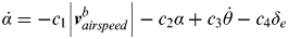 $$\dot \alpha = - c_1 \left\vert {{\bi v}_{airspeed}^b} \right\vert - c_2 \alpha + c_3 \dot \theta - c_4 \delta _e $$
where c 1, c2, c3, and c 4 are determined by the aerodynamic characteristic of the aircraft, θ is the pitch angle, and δ e is the elevator deflection that can be obtained from the servo. Angles in the equation are expressed in radians, and velocities in m/s. All these parameters are obtained through wind tunnel experiment. Since our fixed-wing UAV is a strongly nonlinear system, we linearize the aerodynamic model on the basis of the wind tunnel experiment result at several Mach points (for example, 0·2, 0·3, 0·4, 0·5, 0·6, 0·7, 0·8) and use quadratic interpolation method between Mach numbers. If the Mach points are selected properly, the error caused by the linearization can be ignored with very little cost to the precision. Parameters at 0·5 Mach are given in Table 1.
Aerodynamic parameter for α.

Angle of attack is derived from the dynamic model, which is expressed in Equation (15), and then the airspeed vector can be calculated via Equation (14). As discussed above, ground speed is obtained from Equation (13), motion acceleration is estimated according to Equation (12), and then gravity acceleration is obtained from Equation (11). Finally, by solving Equations (9) and (10), roll and pitch can be deduced from the gravity vector.
3.4. Performance of attitude observer
Although mixed with high frequency noises, the gravity vector has excellent static performance and long-term accuracy. In contrast, an IMU provides better high-frequency information but drifts gradually. Thus, the attitude observation based on gravity vector can efficiently estimate the long-term drift of the INS. Note that the attitude estimation is passed directly into the EKF, which will be discussed in Section 4, and is not low-pass pre-filtered. Actually, the natural low-pass property of the well-tuned EKF effectively filters out the high-frequency noise of the attitude observation and the low-frequency INS drift.
Ideally, if an aircraft keeps flying at a specified height or at a constant vertical speed, the true gravity vector and the motion acceleration should be orthogonal. However, noises are always mixed, which cause the undesirable deviation. Fortunately, this deviation represents the gravity estimate error to some extent. Thus, the error covariance of the attitude observation can be represented by the offset of the orthogonality. Consequently, we introduce a simple assessment of the error covariance as follows:
 $${\bi R}_\phi = \left\{ {\matrix{ {{\bi R}_c} & {(\phi \leqslant \phi _c )} \cr {\left( {\gamma \cdot \cos ^{ - 1} \displaystyle{{\langle \hskip1pt{\bi g},{\bi \hat a} \rangle} \over {\left\vert {\bi g} \right\vert \cdot \left\vert {{\bi \hat a}} \right\vert }}} \right)^2 \cdot {\bi I}_{2 \times 2}} & {(\phi \gt \phi _c )} \cr}} \right.$$
where R c is a two-order constant covariance square matrix on the premise that the roll angle is smaller than a certain value Φ c, 〈g,a〉 is the inner product of vectors g and a, γ is the empirical coefficient related to the characteristic of the IMU and the aircraft. The two-order square matrix R Φ is used in the following filtering process. If the accelerometer is disturbed or angle of attack not accurately estimated, the matrix trace will increase, and the attitude observation will be less referenced correspondingly. The introduction of this adaptive element improves the anti-interference performance of the reconstructed navigation system.
3.5. Heading and velocity observers
In addition to the triaxial angular rate and acceleration, a typical IMU such as ADIS16405 (Analog Devices Inc., 2009) also provides magnetic field strength that is expressed in the body-fixed frame, including  $\hat m_x^b $, $\hat m_y^b $, and $\hat m_z^b $. The horizontal component of magnetic field, X H and Y H, can be derived according to the current attitude:
 $$X_H = \hat m_x^b \cos \theta + \hat m_y^b \sin \theta \sin \phi + \hat m_z^b \sin \theta \cos \phi $$
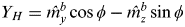 $$Y_H = \hat m_y^b \cos \phi - \hat m_z^b \sin \phi $$
Considering Equations (17) and (18), the magnetic heading ψ m0 can be deduced:
 $${\rm \psi} _{m0} = \left\{ {\matrix{ {\arctan ( - Y_H /X_H ),} & {(X_H \gt 0,Y_H \le 0)} \cr {\pi /2,} & {(X_H = 0,Y_H \lt 0)} \cr {\pi + \arctan ( - Y_H /X_H ),} & {(X_H \lt 0)} \cr {3\pi /2,} & {(X_H = 0,Y_H \gt 0)} \cr {2\pi + \arctan ( - Y_H /X_H ),}& {(X_H \gt 0,Y_H \gt 0)} \cr}} \right.$$
With local magnetic deflection corrected, heading observation is obtained (Barczyk et al., Reference Barczyk, Jost, Kastelan, Lynch and Listmann2010; Barczyk and Lynch, Reference Barczyk and Lynch2011). The heading error is caused by the attitude observation and the magnetic measurement. The former is provided by Equation (16), and the latter is obtained from experimental studies, which is relative to the IMU quality.
Once the wind velocity and Eulerian angles are obtained using the method discussed above, the ground speed can be extracted, and the velocity observer is given as:
 $${\bi \hat v}^n = {\bi \hat v}_{wind}^n + {\bi C}_b^n {\bi \hat v}^b _{airspeed} $$
The observation error consists of the wind speed error and airspeed error. The wind error covariance is obtained using the method discussed in Section 2 when the GPS satellite signal is normal, assuming that the constant component of wind and its error covariance does not vary quickly in a certain period of time during GPS outages. To reduce the computational burden, the airspeed error is simplified to an empirical constant squire matrix with very little cost to filtering quality.
Obtained from barometer and calibrated by the GPS altitude, the barometric height is regarded as the altitude observation during GPS outages. The measurement error is chosen initially in experimental studies and revised online when the GPS receiver works effectively. To reconstruct the measurement equation, all observers discussed in this section will be used in Section 4.
4. RECONSTRUCTION OF THE INTEGRATED NAVIGATION SYSTEM
In this section, the integrated system model is reconstructed during GPS outages, using observations and error covariance matrices that are introduced in Section 3. EKF is applied to estimate INS errors, which are then used to correct the INS solution. The nine-dimensional state variable is chosen, including three dimensions for the platform misalignment angles, velocity errors, and position errors respectively. Dynamic equations for attitude, velocity, and position are written respectively as follows:
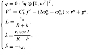 $$\left\{ \matrix{{\bi \dot q} = 0 \cdot 5{\bi q} \otimes [0,{\bi \omega} ^T ]^T, \cr {\bi \dot V}^n = {\bi C}_b^n \ {\bi f}^b - (2{\bi \omega} _{ie}^n + {\bi \omega} _{en}^n ) \times {\bi v}^n + {\bi g}^n, \cr \dot L = \displaystyle{{v_n} \over {R + h}}, \cr \dot \lambda = \displaystyle{{v_e \sec L} \over {R + h}}, \cr \dot h = - v_d, } \right.$$
where q is the quaternion that expresses the attitude, and ω is the angular rate. Vn is the ground velocity expressed in the navigation frame, which can be decomposed into v n, ve, and v d. L, λ, and h are the latitude, longitude, and altitude respectively,
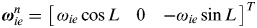 $${\bi \omega} _{ie}^n = \left[ {\matrix{ {\omega _{ie} \cos L} & 0 & { - \omega _{ie} \sin L} \cr}} \right]^T $$
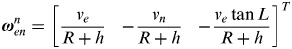 $${\bi \omega} _{en}^n = \left[ {\matrix{ {\displaystyle{{v_e} \over {R + h}}} & { - \displaystyle{{v_n} \over {R + h}}} & { - \displaystyle{{v_e \tan L} \over {R + h}}} \cr}} \right]^T $$
ω ie represents the angular rate of the earth, and R is the radius of the earth. Error propagation equations are obtained from the linearization of Equation (21):
 $$\left\{ \matrix{{\bi \dot \Phi} = {\bi \Phi} \times {\bi \omega} _{in}^n + \delta {\bi \omega} _{in}^n - {\bi C}_b^n \nabla _g^b, \cr \delta {\bi \dot v}^n = - {\bi \Phi} ^n \times {\bi f}^n + \delta {\bi v}^n \times (2{\bi \omega} _{ie}^n + {\bi \omega} _{en}^n ) + {\bi v}^n \times (2\delta {\bi \omega} _{ie}^n + \delta {\bi \omega} _{en}^n ) + {\bi C}_b^n \nabla _a^b, \cr \delta \dot L = \displaystyle{{\delta v_n} \over {R + h}}, \cr \delta \dot \lambda = \displaystyle{{\delta v_e} \over {R + h}}\sec L + \displaystyle{{v_e} \over {R + h}}\sec LtgL\delta L, \cr \delta \dot h = - \delta v_d, } \right.$$
where Φ is the vector of misalignment angle. ωinn is the angular rate of the navigation frame with respect to the inertial frame, which is expressed in the navigation frame. ωenn is the angular rate of the navigation frame with respect to the Earth-Centred Earth-Fixed (ECEF) frame, which is expressed in the navigation frame.∇ gb and ∇ ab are white noise vectors of the gyro and accelerometer respectively. dω ien and dω enn are the differentiations of ωien and ωenn
 $$\delta {\bi \omega} _{ie}^n = \left[ {\matrix { - \delta L\omega _{ie} \sin L} & 0 & { - \delta L\omega _{ie} \cos L} \cr}} \right]^T $$
 $$\delta {\bi \omega} _{en}^n = \left[ {\matrix{ {\displaystyle{{\delta v_e} \over {R + h}} - \delta h\displaystyle{{v_e} \over {(R + h)^2}}} \cr { - \displaystyle{{\delta v_n} \over {R + h}} + \delta h\displaystyle{{v_n} \over {(R + h)^2}}} \cr { - \displaystyle{{\delta v_e \tan L} \over {R + h}} - \delta L\displaystyle{{v_e \sec ^2 L} \over {R + h}} + \delta h\displaystyle{{v_e \tan L} \over {(R + h)^2}}} \cr}} \right]$$
Thus, the system function can be expressed as:
 $${\bi \dot X}(t) = {\bi F}(t){\bi X}(t) + {\bi G}(t){\bi W}(t)$$
 $${\bi X}(t) = [{\bi \Phi} ^T, \delta {\bi v}^T, \delta {\bi P}^T ]^T = [\Phi _n, \Phi _e, \Phi _d, \delta v_n, \delta v_e, \delta v_d, \delta L,\delta \lambda, \delta h]^T $$
 $${\bi W}(t) = \left[ {\matrix{ {\nabla _g^{bT}} & {\nabla _a^{bT}} \cr}} \right]^T $$
which is the same as the system function of the normal INS/GPS integrated navigation system (Titterton and Weston, Reference Titterton and Weston2004).
In Section 3, attitude, heading, velocity, and barometric height have been observed, which can be used to reconstruct the observation equations during GPS outages. The observation vector is redefined as the difference between the INS solutions (I) and their observations (O):
 $${\bi Y}(t) = \left[ {\matrix{ {{\bi Y}_\Phi ^T} & {{\bi Y}_v^T} & {Y_h^T} \cr}} \right]^T $$
 $${\bi Y}_\phi = \left[ {\matrix{ {\phi _I - \phi _O} & {\theta _I - \theta _O} & {\psi _I - \psi _O} \cr}} \right]^T $$
 $${\bi Y}_v = \left[ {\matrix{ {v_{nI} - v_{nO}} & {v_{eI} - v_{eO}} & {v_{dI} - v_{dO}} \cr}} \right]^T $$
 $$Y_h^{} = h_I - h_O $$
Where Y Φ is the attitude observation vector, Y v is the velocity observation vector, and Y h is the altitude observation. The observation equations can be written respectively as
 $${\bi Y}_\phi = {\bi C}_\Phi {\bi \Phi} + {\bi V}_\phi $$
 $${\bi Y}_v = {\bi I}_{3 \times 3} \delta {\bi v} + {\bi V}_v $$
 $$Y_h = \delta h + V_h $$
Where V Φ, V v, V h are noises of the observations, with the covariance matrix R Φ, R v, R h respectively. C Φ is the transformation matrix from the platform misalignment angles to the attitude errors (Jian, Reference Jian2007):
 $${\bi C}_\Phi = \left[ {\matrix{ {\displaystyle{{C_{13} C_{31} - C_{11} C_{33}} \over {C_{31}^2 + C_{33}^2}}} & {\displaystyle{{C_{21} C_{33} - C_{23} C_{31}} \over {C_{31}^2 + C_{33}^2}}} & 0 \cr { - \displaystyle{{C_{12}} \over {\sqrt {1 - C_{32}^2}}}} & { - \displaystyle{{C_{22}} \over {\sqrt {1 - C_{32}^2}}}} & 0 \cr {\displaystyle{{C_{22} C_{32}} \over {C_{12}^2 + C_{22}^2}}} & {\displaystyle{{C_{12} C_{32}} \over {C_{12}^2 + C_{22}^2}}} & 1 \cr}} \right]$$
Thus, the observation equation is united as
 $${\bi Y}(t) = {\bi H}(t){\bi X}(t) + {\bi V}(t)$$
 $${\bi H}(t) = \left[ {\matrix{ {{\bi C}_\Phi} & {{\bi 0}_{3 \times 3}} & {{\bi 0}_{3 \times 3}} \cr {{\bi 0}_{3 \times 3}} & {{\bi I}_{3 \times 3}} & {{\bi 0}_{3 \times 3}} \cr {{\bi 0}_{1 \times 3}} & {{\bi 0}_{1 \times 3}} & {\left[ {00,1} \right]} \cr}} \right]$$
Once the system function and the reconstructed observation equation are established as Equations (27) and (38), the discrete model can be obtained:
 $$\left\{ \matrix{\hskip -3pt{\bi X}_k = {\bi \Phi} _{k,k - 1} {\bi X}_{k - 1} + {\bi \Gamma} _{k - 1} {\bi W}_{k - 1} \cr \hskip -2pt{\bi Y}_k = {\bi H}_k {\bi X}_k + {\bi V}_k } \right.$$
Φk,k-1 and Γk-1 are discrete forms of F(t) and G(t) respectively (Yuan et al., Reference Yuan, Yu and Chen1993):
 $${\bi \Phi} _{k,k - 1} = e^{{\bi F}T} = \sum\limits_{n = 0}^\infty {[{\bi F}(t_k )T]^n /} n!$$
 $${\bi \Gamma} _{k - 1} = \left\{ {\sum\limits_{n = 1}^\infty {\left[ {\displaystyle{1 \over {n!}}({\bi F}(t_k )T)^{n - 1}} \right]}} \right\}{\bi G}(t_k )T$$
where T is the discrete time, which is determined by the update frequency of observers. Once GPS outages occur, the system model will be reconstructed correspondingly. Estimated through an EKF, the state vector is then used to correct the INS solution. Rather than keeping the navigation system working in prediction mode, the new closed-loop model is reconstructed to resist INS errors.
5. EXPERIMENTAL RESULTS
5.1. Real-time hardware-in-loop simulation platform
In this section, the experimental results of the wind estimate, attitude, and velocity observations are described, and the reconstructed navigation system is assessed, comparing to the INS/GPS integrated system. All the experiments are implemented on our real-time hardware-in-loop simulation platform, as shown in Figure 1. Our simulation platform consists of an embedded master control computer, actuators that are actually used on our vehicle, a dSPACE real-time simulation computer, a three-axis rotator, a ground control station, and a black box.
Real-time hardware-in-loop simulation system.

The master control computer, embedded with an IMU (ADIS16405), is fixed on the rotator, and acts as the core of the whole system, which plans the flight path, estimates navigation information using methods proposed above, implements controls of each loop with actuators, stores information to a black box, and communicates with the user through the ground control station. The gyro in the ADIS16405 has 0·007°/s bias, 2·0°/√hr random walk and 0·9°/s RMS output noise. The actuators, including servo and engine, execute orders from the master computer and return responses. The dSPACE real-time simulation platform acts as the controlled object (our fixed-wing UAV), which receives information from actuators and computes the object state (GPS data, accelerometer output, and air speedometer measurement) based on the aerodynamic model. The rotator, equipping our master control computer, rotates according to the attitude of the vehicle and engenders the synchronous reaction of the IMU.
We involved as much hardware and software as possible, which are all really used on our UAV. Although the math models built sometimes cannot exactly match the real aircraft, which will influence the fidelity of experiment results, the simulation system has proved quite credible due to the remarkable consistency of the experiment information with actual flight results, considering our actual flight tests over the past four years.
In our experiment, angular rate and magnetic on board are real outputs of the IMU that are fixed on the rotator. However, it is impossible to use other real measurements in simulation, such as GPS frame, accelerometer output, airspeed and barometric height. All this information is generated from the aerodynamic model. Accelerometer output is transmitted into the on board computer periodically in 0·001 s, and other measurements in 0·1 s. INS solution updates periodically in 0·004 s. Observations and EKF estimations are carried out every 0·1 s.
5.2. Observation performance test
To evaluate the performance of observers discussed in Sections 2 and 3, the proposed algorithm was implemented on the embedded computer. In our first simulation, the constant component of wind velocity was estimated and assessed. Produced by a wind-generator, the wind changed the aerodynamic force, and finally resulted in disturbance of the vehicle. Then, the correspondingly influenced airspeed and GPS information were transmitted to the embedded control computer that was strapped on the rotator. INS and GPS were integrated by the on board computer using an EKF, and the result was regarded as the reference value. The initial value of the wind state was cleared to zero and its initial predicted variances were assumed to be 502, 502, 502, 202, 202, and 202, respectively, in units of m2/s2. The process noise variances of the wind model were assigned 52, 52, and 52. The measurement noise variances were assigned 202, 202, and 202. Once the simulation started, the on board computer began to estimate wind speed using method illustrated in Section 2. Estimate results and their true values were both stored in the black box, and contrasts are shown in Figure 2. Estimate errors are shown in Figure 3.
Wind speed estimates using GPS/INS integrated system.
Errors of wind speed estimates.
The wind observer can estimate wind speed effectively so long as the GPS receiver works well. At the time simulation started, the observer began to track the real wind state, and then observation errors quickly converged. Once GPS outages occur, the constant part of the newest estimation will be used in the airspeed compensation as discussed in Section 3.
The error of the wind-compensated velocity is shown in Figure 4, and the uncompensated airspeed is compared. Subtraction of wind velocity from airspeed as expressed in Equation (13) markedly decreases the velocity observation error. The error of the attitude obtained from the compensated gravity vector is shown in Figure 5, contrasted with the error of attitude calculated from the raw measurement of the accelerometer. When the UAV pitches or rolls, the error of uncompensated attitude quickly deteriorates. It is shown in Figure 5 that the error of uncompensated estimate of the aircraft roll almost completely equals the inverse of the true value (the GPS/INS solution). Compensation of the motion acceleration as expressed in Equation (11) effectively improves the accuracy of the attitude observer.
Errors of velocity obtained from the wind-compensated airspeed and the uncompensated solution.
Errors of attitude obtained from the motion-compensated gravity vector and the uncompensated solution.
5.3. The reconstructed integrated system
To assess the performance of the reconstructed integrated system, we planned a trajectory shown in Figure 6, and the UAV was commanded to fly at a speed of 160 m/s. As assumed in Section 3, the fixed-wing aircraft tried to maintain altitude and velocity during flight. However, in order to evaluate the algorithm robustness, vertical motions were added to straight flight. The initial value of the system state (INS errors) were assigned to zero, which had the initial predicted variances: (1·0°)2, (1·0°) 2, (2·0°) 2, (0·4 m/s)2, (0·4 m/s)2, (0·4 m/s)2, (5 m)2, (5 m) 2, and (10 m) 2, respectively. The process noise variances of INS were assigned (0·2°/s)2, (0·2°/s)2, (0·4°/s)2, (0·2 m/s2)2, (0·2 m/s2)2 , and (0·2 m/s2)2. The attitude, velocity and altitude measurement noise variances were assumed (2·0°)2, (2·0°)2, (4·0°)2, (0·1 m/s)2, (0·1 m/s)2, (0·1 m/s)2 , and (5 m)2.
Flight path for the experiment.
During the first 90 seconds, the GPS satellite signal was unobstructed, and wind speed was estimated. At 90 seconds, the GPS signal was assumed to be blocked, and the traditional EKF had to work in prediction mode. Meanwhile, the integrated system was reconstructed, and the special observers along with the reconstructed integrated filter began to work. Also, the typical INS/GPS integrated navigation system kept working to provide reference values. Figure 7 shows errors of the INS-only solution (prediction mode of the INS/GPS filter), which diverged quickly during GPS outages.
Errors of the INS-only solution.
Attitude from the reconstructed integrated system was compared with the true value in Figure 8. Errors of roll and pitch were effectively limited after system reconstruction, which was much better than the INS-only solution in Figure 7. However, attitude errors always existed, due to the attitude observation that was disturbed by the angle of attack and the varying wind speed.
Attitude errors of INS/pressure integrated system.
As shown in Figure 8, the roll error increases correspondingly as the UAV banks. Fortunately, the disturbed errors are estimated and corrected gradually, owing to the good low-frequency property of the gravity vector observer. As the UAV climbs or descends suddenly, the level-flight assumption is not well satisfied, so the pitch error increases simultaneously. However, the limited pitch error proves that the new algorithm is somewhat robust for the level-flight and constant-velocity assumption.
In order to illustrate the effectiveness of the attitude estimation further, attitude errors for different flight manoeuvres are shown in Figure 9. Attitude curves on the left side of the figure represent the corresponding flight manoeuvres, including accelerating, turning, climbing, and nosing down, while attitude errors relative to the true value are shown on the right. Although attitude precision decreases slightly in manoeuvring, errors are still limited in an acceptable region and remain convergent.
Attitude errors for different flight manoeuvres.
Figure 10 shows the comparison between velocity estimate from the reconstructed integrated system and the true value. Well restricted by the velocity observer, errors in three directions were all limited, while the INS-only solution diverged quickly as shown in Figure 7. It is shown that the northward velocity v n and the eastward velocity v e converge much better than the downward velocity v d. The analysis of this difference is given as follows.
Errors of estimated velocity.
The velocity observer, expressed in the navigation frame, is transformed from velocity in the body-fixed frame:
 $${\bi \hat v}_{}^n = {\bi C}_b^n {\bi \hat v}^b _{} $$
Downward velocity v d can be expressed as
 $$\hat v_d = - \sin \theta \cdot \hat v_x + \sin \phi \cos \theta \cdot \hat v_y + \cos \phi \cos \theta \cdot \hat v_z $$
For a fixed-wing UAV, v y and v z are much smaller than v x, which is about 160 m/s. Thus, v d is mainly determined by the first component –sin θv x. When the aircraft pitches promptly, pitch error increases for the reason that the level-flight assumption is not strictly satisfied, which produces an inverse v d error (the v d estimate subtract the true value). Comparing Figure 10 with Figure 8, it is clear that the phase of v d error is approximately the inverse of the pitch error phase. In contrast, horizontal velocity v n and v e are less sensitive to attitude errors.
Since no positioning measurement is involved in our algorithm during GPS outages, observability of position error is too weak to keep it convergent. Consequently, horizontal error diverges gradually as shown in Figure 11. However, the divergence speed of the horizontal error is much slower than those of INS-only system as shown in Figure 7. Since the barometric height is corrected and involved in the reconstructed system, the altitude error remains convergent.
Errors of estimated position.
It should be noted that the reconstructed integrated navigation system is sensitive to “wild” wind in some way. If the wind changes quickly or the velocity and altitude are not exactly maintained during GPS outages, the navigation accuracy will decrease correspondingly. For example, if the original “wild” wind suddenly vanishes during GPS outages, the velocity estimation will deteriorate gradually and finally reach the case that is shown in Figure 4, which will affect attitude. In these scenarios, our new method might be ineffective.
However, our method is somewhat robust to resist disturbances. Relatively speaking, attitude and velocity are much more important than positioning for aircraft to maintain safe flight. Even if the position estimate diverges gradually, the convergent attitude and velocity save much more time for UAVs to recapture GPS or fulfil an emergency landing.
6. CONCLUSIONS
In this paper, a new navigation algorithm was proposed to bridge GPS outages for fixed-wing UAVs based on the typical INS/GPS integrated navigation system. A dynamic model for wind, angle of attack, and motion acceleration was introduced to estimate ground velocity and gravity vector, so that the integrated navigation system could be reconstructed during GPS outages. Furthermore, a comparison was carried out between the traditional method and the proposed algorithm based on hardware-in-loop real-time simulations for our fixed-wing UAV. Results show that the reconstructed integrated navigation system has its potential as a simple and robust substitution for the INS/GPS integrated navigation system for fixed-wing UAVs during GPS outages.
ACKNOWLEDGEMENTS
This work is supported partially sponsored by the National Natural Science Foundation of China (grant number61004066) and Science and Technology Project of Zhejiang Province (grant number 2011C23106).


